Post-Tensioned Concrete Masonry Wall Design
INTRODUCTION
The 1999 Building Code Requirements for Masonry Structures, ACI 530/ASCE 5/TMS 402 (ref. 1), was the first masonry code in the United States to include general design provisions for prestressed masonry. Prestressing masonry is a process whereby internal compressive stresses are introduced to counteract tensile stresses resulting from applied loads. Compressive stresses are developed within the masonry by tensioning a steel tendon, which is anchored to the top and bottom of the masonry element (see Figure 1). Post-tensioning is the primary method of prestressing, where the tendons are stressed after the masonry has been placed. This TEK focuses on the design of concrete masonry walls constructed with vertical post-tensioned tendons.
Advantages
Prestressing has the potential to increase the flexural strength, shear strength and stiffness of a masonry element. In addition to increasing the strength of an element, prestressing forces can also close or minimize the formation of some cracks. Further, while research (refs. 14, 15) indicates that ductility and energy dissipation capacity are enhanced with prestressing, Building Code Requirements for Masonry Structures (ref. 1) conservatively does not take such performance into account.
Post-tensioned masonry can be an economical alternative to conventionally reinforced masonry. One major advantage of prestressing is that it allows a wall to be reinforced without the need for grout. Also, the number of prestressing tendons may be less than the number of reinforcing bars required for the same flexural strength.
Post-tensioning masonry is primarily applicable to walls, although it can also be used for beams, piers, and columns. Vertical post-tensioning is most effective for increasing the structural capacity of elements subjected to relatively low axial loads. Structural applications include loadbearing, nonloadbearing and shear walls of tall warehouses and gymnasiums, and commercial buildings, as well as retaining walls and sound barrier walls. Post-tensioning is also an option for strengthening existing walls.

MATERIALS
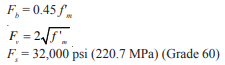
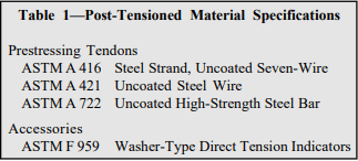
Post-tensioned wall construction uses standard materials: units, mortar, grout, and perhaps steel reinforcement. In addition, post-tensioning requires tendons, which are steel wires, bars or strands with a higher tensile strength than conventional reinforcement. Manufacturers of prestressing tendons must supply stress relaxation characteristics for their material if it is to be used as a prestressing tendon. Specifications for those materials used specifically for post-tensioning are given in Table 1. Other material specifications are covered in references 9 through 12. Construction is covered in Post-Tensioned Concrete Masonry Wall Construction, TEK 03-14 (ref. 3).
CORROSION PROTECTION
As with conventionally reinforced masonry structures, Building Code Requirements for Masonry Structures (ref. 1) mandates that prestressing tendons for post-tensioned masonry structures be protected against corrosion. As a minimum, the prestressing tendons, anchors, couplers and end fittings in exterior walls exposed to earth or weather must be protected. All other walls exposed to a mean relative humidity exceeding 75% must also employ some method of corrosion abatement. Unbonded tendons can be protected with galvanizing, epoxy coating, sheathing or other alternative method that provides an equivalent level of protection. Bonded tendons are protected from corrosion by the corrugated duct and prestressing grout in which they are encased.
DESIGN LOADS
As for other masonry structures, minimum required design loads are included in Minimum Design Loads for Buildings and Other Structures, ASCE 7 (ref. 5), or the governing building codes. If prestressing forces are intended to resist lateral loads from earthquake, a factor of 0.9 should be applied to the strength level prestress forces (0.6 for allowable stress design) as is done with gravity loads.
STRUCTURAL DESIGN
The design of post-tensioned masonry is based on allowable stress design procedures, except for laterally restrained tendons which use a strength design philosophy. Building Code Requirements for Masonry Structures (ref. 1) prescribes allowable stresses for unreinforced masonry in compression, tension and shear, which must be checked against the stresses resulting from applied loads.
The flexural strength of post-tensioned walls is governed by either the flexural tensile stress of the masonry (the flexural stress minus the post-tensioning and dead load stress), the masonry compressive stress, the tensile stress within the tendon, the shear capacity of the masonry or the buckling capacity of the wall.
Masonry stresses must be checked at the time of peak loading (independently accounting for both short-term and long-term losses), at the transfer of post-tensioning forces, and during the jacking operation when bearing stresses may be exceeded. Immediately after transfer of the post-tensioning forces, the stresses in the steel are the largest because long-term losses have not occurred. Further, because the masonry has had little time to cure, the stresses in the masonry will be closer to their capacity. Once long-term losses have transpired, the stresses in both the masonry and the steel are reduced. The result is a coincidental reduction in the effective capacity due to the prestressing force and an increase in the stresses the fully cured masonry can resist from external loads.
Effective Prestress
Over time, the level of prestressing force decreases due to creep and shrinkage of the masonry, relaxation of the prestressing tendons and potential decreases in the ambient temperature. These prestressing losses are in addition to seating and elastic shortening losses witnessed during the prestressing operation. In addition, the prestressing force of bonded tendons will decrease along the length of the tendon due to frictional losses. Since the effective prestressing force varies over time, the controlling stresses should be checked at several stages and loading conditions over the life of the structure.
The total prestress loss in concrete masonry can be assumed to be approximately 35%. At the time of transfer of the prestressing force, typical losses include: 1% seating loss + 1% elastic shortening = 2%. Additional losses at service loads and moment strength include:
| relaxation | 3% |
| temperature | 10% |
| creep | 8% |
| CMU shrinkage | 7% |
| contingency | 5% |
| total | 33% |
Prestress losses need to be estimated accurately for a safe and economical structural design. Underestimating losses will result in having less available strength than assumed. Overestimating losses may result in overstressing the wall in compression.
Effective Width
In theory, a post-tensioning force functions similarly to a concentrated load applied to the top of a wall. Concentrated loads are distributed over an effective width as discussed in the commentary on Building Code Requirements for Masonry Structures (ref. 1). A general rule-of-thumb is to use six times the wall thickness as the effective width.
Elastic shortening during post-tensioning can reduce the stress in adjacent tendons that have already been stressed. Spacing the tendons further apart than the effective width theoretically does not reduce the compressive stress in the effective width due to the post-tensioning of subsequent tendons. The applied loads must also be consolidated into the effective width so the masonry stresses can be determined. These stresses must be checked in the design stage to avoid overstressing the masonry.
Flexure
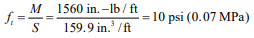
Tensile and compressive stresses resulting from bending moments applied to a section are determined in accordance with conventional elastic beam theory. This results in a triangular stress distribution for the masonry in both tension and compression. Maximum bending stress at the extreme fibers are determined by dividing the applied moment by the section modulus based on the minimum net section.
Net Flexural Tensile Stress
Sufficient post-tensioning force needs to be provided so the net flexural tensile stress is less than the allowable values. Flexural cracking should not occur if post-tensioning forces are kept within acceptable bounds. Flexural cracking due to sustained post-tensioning forces is believed to be more severe than cracking due to transient loading. Flexural cracks due to eccentric post-tensioning forces will remain open throughout the life of the wall, and may create problems related to water penetration, freeze-thaw or corrosion. For this reason, Building Code Requirements for Masonry Structures (ref. 1) requires that the net flexural tensile stress be limited to zero at transfer of the post-tensioning force and for service loadings with gravity loads only.
Axial Compression
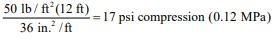
Compressive stresses are determined by dividing the sum of the post-tensioning and gravity forces by the net area of the section. They must be less than the code prescribed (ref. 1) allowable values of axial compressive stress.
Walls must also be checked for buckling due to gravity loads and post-tensioning forces from unrestrained tendons. Laterally restrained tendons can not cause buckling; therefore only gravity compressive forces need to be checked for buckling in walls using laterally restrained tendons. Restraining the tendons also ensures that the tendons do not move laterally in the wall when the masonry deflects. The maximum compressive force that can be applied to the wall based upon ¼ buckling is Pe, per equation 2-11 of Building Code Requirements for Masonry Structures (ref. 1).
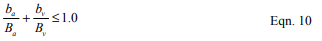
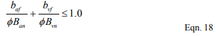
Combined Axial and Flexural Compressive Stress
Axial compressive stresses due to post-tensioning and gravity forces combine with flexural compressive stresses at the extreme fiber to result in maximum compressive stress. Conversely, the axial compressive stresses combine with the flexural tensile stresses to reduce the absolute extreme fiber stresses. To ensure the combination of these stresses does not exceed code prescribed allowable stresses, a unity equation is checked to verify compliance. Employing this unity equation, the sum of the ratios of applied-to-allowable axial and flexural stresses must be less than one. Unless standards (ref. 5) limit its use, an additional one-third increase in allowable stresses is permitted for wind and earthquake loadings, as is customary with unreinforced and reinforced masonry. Further, for the stress condition immediately after transfer of the post-tensioning force, a 20% increase in allowable axial and bending stresses is permitted by Building Code Requirements for Masonry Structures (ref. 1).
Shear
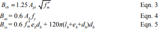
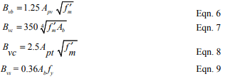
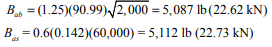
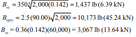
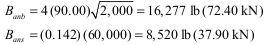
As with all stresses, shear stresses are resisted by the net area of masonry, and the wall is sized such that the maximum shear stress is less than the allowable stress. In addition, the compressive stress due to post-tensioning can be relied on to increase allowable shear stresses in some circumstances.
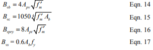
Post-Tensioning Tendons
The stress in the tendons is limited (ref. 1) such that:
- the stress due to the jacking force does not exceed 0.94fpy, 0.80fpu, nor that recommended by the manufacturer of the tendons or anchorages,
- the stress immediately after transfer does not exceed 0.82fpy nor 0.74fpu, and
- the stress in the tendons at anchorages and couplers does not exceed 0.78fpy nor 0.70fpu.
DETERMINATION OF POST-TENSIONING FORCES
Case (a) after prestress losses and at peak loading:
Assuming that the moment, M, due to wind or earthquake loadings is large relative to the eccentric load moment, the critical location will be at the mid-height of the wall for simply-supported walls, and the following equations apply (bracketed numbers are the applicable Building Code Requirements for Masonry Structures (ref. 1) equation or section numbers):

The 1.33 factor in Equation [2-10] represents the one- third increase in allowable stress permitted for wind and earthquake loadings. If the moment, M, is a result of soil pressures (as is the case for retaining walls), the 1.33 factor in Equation [2-10] must be replaced by 1.00.
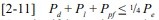
Note that if the tendons are laterally restrained, Ppf should not be included in Equation [2-11].
(under the load combination of prestressing force and dead load only)
Additional strength design requirements for laterally restrained tendons:

Equation 4-3 above applies to members with uniform width, concentric reinforcement and prestressing tendons and concentric axial load. The nominal moment strength for other conditions should be determined based on static moment equilibrium equations.


Case (b) at transfer of post-tensioning:
Assuming that vertical live loads are not present during post-tensioning, the following equations apply. The worst case is at the top of the wall where post-tensioning forces are applied.

For cantilevered walls, these equations must be modified to the base of the wall.
If the eccentricity of the live load, Pl, is small, neglecting the live load in Equation [2-10] may also govern.
Case (c) bearing stresses at jacking:
Bearing stresses at the prestressing anchorage should be checked at the time of jacking. The maximum allowable bearing stress at jacking is 0.50f’mi per Building Code Requirements for Masonry Structures (ref. 1) section 4.9.4.2.
DESIGN EXAMPLE
Design a simply-supported exterior wall 12 ft (3.7 m) high for a wind load of 15 psf (0.72 kPa). The wall is constructed of concrete masonry units complying with ASTM C 90 (ref. 6). The units are laid in a full bed of Type S Portland cement lime mortar complying with ASTM C 270 (ref. 7). The specified compressive strength of the masonry (f’m) is 1,500 psi (10.3 MPa). The wall will be post-tensioned with 7/16 in. (11 mm) diameter laterally restrained tendons when the wall achieves a compressive strength of 1,250 psi (8.6 MPa). Axial load and prestress are concentric.
Given:
8 in. (203 mm) CMU
tf = 1.25 in. (32 mm)
f’m = 1,500 psi (10.3 MPa)
f’mi = 1,250 psi (8.6 MPa)
Fbt = 25 psi (0.17 MPa) (Type S Portland cement/lime mortar)
fpy = 100 ksi (690 MPa) (bars)
fpu = 122 ksi (840 MPa)
Aps = 0.14 in² (92 mm²)
Es = 29 x 106 psi (200 GPa)
Em = 900 f’m = 1.35 x 10⁶ psi (9,300 MPa)
n = Es/Em = 21.5
d = 7.625/2 in. = 3.81 in. (97 mm) (tendons placed in the center of the wall)
unit weight of CMU wall = 39 psf (190 kg/m²) (ref. 13)
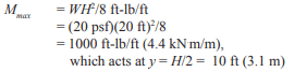
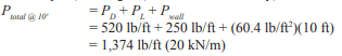
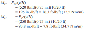
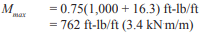
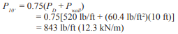
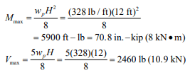
Loads: M = wh²/8 = (15)(12)²/8 = 270 ft-lb (366 N-m)
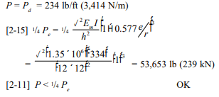
Pd at mid-height = (39)(12)/2 = 234 lb/foot of wall (3,410 N/m) (Pl = 0)
Maximum tendon stresses:
Determine governing stresses based on code limits (ref. 1):
| At jacking: | 0.94 fpy = 94.0 ksi (648 MPa) |
| 0.80 fpu = 97.6 ksi (673 MPa) | |
| At transfer: | 0.82 fpy = 82.0 ksi (565 MPa) |
| 0.74 fpu = 90.3 ksi (623 MPa) | |
| At service loads: | 0.78 fpy = 78.0 ksi (538 MPa) ⇒ governs |
| 0.70 fpu = 85.4 ksi (589 MPa) |
Because the tendon’s specified tensile strength is less than 150 ksi (1,034 MPa), fps = fse (per ref. 1 section 4.5.3.3.4).
Prestress losses: Assume 35% total loss (as described in the Effective Prestress section above).
Tendon forces:
Determine the maximum tendon force, based on the governing tendon stress determined above for each case of jacking, transfer and service. At transfer, include 2% prestress losses. At service, include the full 35% losses.
Tendon capacity at jacking = 0.94 fpyAps = 13.3 kips (59 kN)
Tendon capacity at transfer = 0.82 fpyAps A x 0.98 = 11.4 kips (51 kN) (including transfer losses)
Tendon capacity at service = 0.78 fpyAps A x 0.65 = 7.2 kips (32 kN) (including total losses)
Try tendons at 48 in. (1,219 mm) on center (note that this tendon spacing also corresponds to the maximum effective prestressing width of six times the wall thickness).
Determine prestressing force, based on tendon capacity determined above:
at transfer: Ppi = 11.4 kips/4 ft = 2,850 lb/ft (41.6 kN/m)
at service: Ppf = 7.2 kips/4 ft = 1,800 lb/ft (26.3 kN/m)
Wall section properties: (ref. 8)
8 in. (203 mm) CMU with full mortar bedding:
An = 41.5 in.²/ft (87,900 mm²/m)
I = 334 in.4/ft (456 x 106 mm4/m)
S = 87.6 in.³/ft (4.71 x 106 mm³/m)
r = 2.84 in. (72.1 mm)
At service loads:
At service, the following are checked: combined axial compression and flexure using the unity equation (equation 2-10); net tension in the wall; stability by ensuring the compressive load does not exceed one-fourth of the buckling load, Pe, and shear and moment strength.
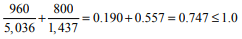
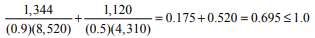
Check combined axial compression and flexure:


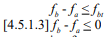
Check tension for load combination of prestress force and dead load only (per ref. 1 section 4.5.1.3):

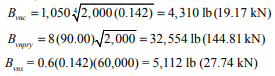
Check stability:
Because the tendons are laterally restrained, the prestressing force, Ppf, is not considered in the determination of axial load ( per ref. 1 section 4.5.3.2), and the wall is not subject to live load in this case, so equation 2-11 reduces to:
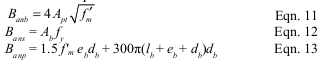
Check moment strength:
Building Code Requirements for Masonry Structures section 4.5.3.3 includes the following criteria for moment strength of walls with laterally restrained tendons:
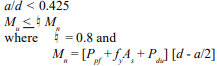
In addition, the compression zone must fall within the masonry, so a < tf.
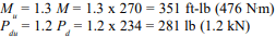
where 1.3 and 1.2 are load factors for wind and dead loads, respectively.

At transfer:
Check combined axial compression and flexure using the unity equation (equation 2-10) and net tension in the wall.

Check tension for load combination of prestress force and dead load only (per ref. 1 section 4.5.1.3):

Therefore, use 7/16 in. (11 mm) diameter tendons at 48 in. (1,219 mm) o.c. Note that although wall design is seldom governed by out-of-plane shear, the shear capacity should also be checked.
NOTATIONS
An net cross-sectional area of masonry section, in.² (mm²)
Aps threaded area of post-tensioning tendon, in.² (mm²)
As cross-sectional area of mild reinforcement, in.² (mm²)
a depth of an equivalent compression zone at nominal strength, in. (mm)
b width of section, in. (mm)
d distance from extreme compression fiber to centroid of prestressing tendon, in. (mm)
Es modulus of elasticity of prestressing steel, psi (MPa)
Em modulus of elasticity of masonry, psi (MPa)
ed eccentricity of dead load, in. (mm)
el eccentricity of live load, in. (mm)
ep eccentricity of post-tensioning load, in. (mm)
Fa allowable masonry axial compressive stress, psi (MPa)
Fai allowable masonry axial compressive stress at transfer, psi (MPa)
Fb allowable masonry flexural compressive stress, psi (MPa)
Fbi allowable masonry flexural compressive stress at transfer, psi (MPa)
Fbt allowable flexural tensile strength of masonry, psi (MPa)
fa axial stress after prestress loss, psi (MPa)
fai axial stress at transfer, psi (MPa)
fb flexural stress after prestress loss, psi (MPa)
fbi flexural stress at transfer, psi (MPa)
f’m specified compressive strength of masonry, psi (MPa)
f’mi specified compressive strength of masonry at time of transfer of prestress, psi (MPa)
fps stress in prestressing tendon at nominal strength, psi (MPa)
fpu specified tensile strength of prestressing tendon, ksi (MPa)
fpy specified yield strength of prestressing tendon, ksi (MPa)
fse effective stress in prestressing tendon after all pre-stress losses have occurred, psi (MPa)
fy specified yield strength of steel for reinforcement and anchors, psi (MPa)
h masonry wall height, in. (mm)
I moment of inertia of net wall section of extreme fiber tension or compression, in.4/ft (mm4/m)
M moment due to lateral loads, ft-lb (N⋅m)
Mn nominal moment strength, ft-lb (N⋅m)
Mu factored moment due to lateral loads, ft-lb (N⋅m)
n modular ratio of prestressing steel and masonry (Es/Em)
Pd axial dead load, lb/ft (kN/m)
Pdu factored axial dead load, lb/ft (kN/m)
Pe Euler buckling load, lb/ft (kN/m)
Pl axial live load, lb/ft (kN/m)
Plu factored axial live load, lb/ft (kN/m)
Ppi prestress force at transfer, lb/ft (kN/m)
Ppf prestress force including losses, lb/ft (kN/m)
r radius of gyration for net wall section, in. (mm)
S section modulus of net cross-sectional area of the wall, in.³ /ft (mm³/m)
tf face shell thickness of concrete masonry, in. (mm)
w applied wind pressure, psf (kPa)
¤ strength reduction factor = 0.8
REFERENCES
- Building Code Requirements for Masonry Structures, ACI 530-02/ASCE 5-02/TMS 402-02. Reported by the Masonry Standards Joint Committee, 2002.
- Building Code Requirements for Structural Concrete, ACI 318-99. Detroit, MI: American Concrete Institute, Revised 1999.
- Construction of Post-Tensioned Concrete Masonry Walls, TEK 03-14. Concrete Masonry & Hardscapes Association, 2002.
- International Building Code. International Code Council, 2000.
- Minimum Design Loads for Buildings and Other Structures, ASCE 7-98, American Society of Civil Engineers, 1998.
- Standard Specification for Loadbearing Concrete Masonry Units, ASTM C 90-01a. American Society for Testing and Materials, 2001.
- Standard Specification for Mortar for Unit Masonry, ASTM C 270-01. American Society for Testing and Materials, 2001.
- Weights and Section Properties of Concrete Masonry Assemblies, CMU-TEC-002-23, Concrete Masonry & Hardscapes Association, 2023.
- Concrete Masonry Unit Shapes, Sizes, Properties, and Specifications, CMU-TEC-001-23, Concrete Masonry & Hardscapes Association, 2023.
- Mortars for Concrete Masonry, TEK 09-01A. Concrete Masonry & Hardscapes Association, 2001.
- Grout for Concrete Masonry, TEK 09-04. Concrete Masonry & Hardscapes Association, 2005.
- Steel for Concrete Masonry Reinforcement, TEK 12-04D. Concrete Masonry & Hardscapes Association, 1998.
- Weights and Section Properties of Concrete Masonry Assemblies, CMU-TEC-002-23, Concrete Masonry & Hardscapes Association, 2023.
- Schultz, A.E., and M.J. Scolforo, An Overview of Prestressed Masonry, TMS Journal, Vol. 10, No. 1, August 1991, pp. 6-21.
- Schultz, A.E., and M.J. Scolforo, Engineering Design Provisions for Prestressed Masonry, Part 1: Masonry Stresses, Part 2: Steel Stresses and Other Considerations, TMS Journal, Vol. 10, No. 2, February 1992, pp. 29-64.
- Standard Specification for Steel Strand, Uncoated Seven-Wire for Prestressed Concrete, ASTM A 416-99. American Society for Testing and Materials, 1999.
- Standard Specification for Uncoated Stress-Relieved Steel Wire for Prestressed Concrete, ASTM A 421-98a. American Society for Testing and Materials, 1998.
- Standard Specification for Uncoated High-Strength Steel Bar for Prestressed Concrete, ASTM A 722-98. American Society for Testing and Materials, 1998.
- Standard Specification for Compressible-Washer-Type Direct Tension Indicators for Use with Structural Fasteners, ASTM F 959-01a. American Society for Testing and Materials, 2001.