Resources

Empirical Design of Concrete Masonry Walls

INTRODUCTION

Empirical design is a procedure of proportioning and sizing unreinforced masonry elements based on known historical performance for a given application. Empirical provisions preceded the development of engineered masonry design, and can be traced back several centuries. This approach to design is based on historical experience in lieu of analytical methods. It has proven to be an expedient design method for typical loadbearing structures subjected to relatively small wind loads and located in areas of low seismic risk. Empirical design has also been used extensively for the design of exterior curtain walls and interior partitions.

Using empirical design, vertical and lateral load resistance is governed by prescriptive criteria which include wall height to thickness ratios, shear wall length and spacing, minimum wall thickness, maximum building height, and other criteria, which have proven to be effective through years of experience.

This TEK is based on the provisions of Section 2109 of the International Building Code (IBC) (ref. 1). These empirical design requirements do not apply to other design methods such as allowable stress or limit states design. For empirical design of foundation walls, see TEK 15-01B, Allowable Stress Design of Concrete Masonry Foundation Walls (ref. 2)

APPLICABILITY OF EMPIRICAL DESIGN

The IBC allows elements of masonry structures to be designed by empirical methods when assigned to Seismic Design Category (SDC) A, B or C, subject to additional restrictions described below. When empirically designed elements are part of the seismic lateral force resisting system, however, their use is limited to SDC A.

Empirical design has primarily been used with masonry laid in running bond. When laid in stack bond, the IBC requires a minimum amount of horizontal reinforcement (0.003 times the wall’s vertical cross-sectional area and spaced not more than 48 in. (1,219 mm) apart).

In addition, buildings that rely on empirically designed masonry walls for lateral load resistance are allowed up to 35 ft (10.7 m) in height.

The 2003 IBC restricts empirical design to locations where the basic wind speed (three-second gust, not fastest mile) is less than or equal to 110 mph (79 m/s), as defined in Minimum Design Loads for Buildings and Other Structures, ASCE 7 (ref. 3). A wind speed of this velocity generally applies along the East and Gulf coasts of the United States.

The 2006 IBC further refines the empirical design limitations. Whereas with the 2003 IBC, the designer need only check the SDC and basic wind speed, with the 2006 IBC, to use empirical design the designer must check:

  • SDC,
  • basic wind speed,
  • building height, and
  • location of gravity loads resultant.

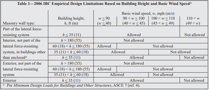
The limitations based on SDC are the same as in the 2003 IBC, described above. Building height and basic wind speed conditions where empirical design is permitted under the 2006 IBC are summarized in Table 1.

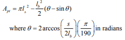
The 2006 IBC also requires the resultant of gravity loads to fall within the kern of the masonry element, to avoid imparting tension to the element. This area is defined as: within the center third of the wall thickness, or, for foundation piers, within the central area bounded by lines at one-third of each cross-sectional dimension of the pier.

DESIGN PROVISIONS

Minimum Wall Thickness

Empirically designed (unreinforced) bearing walls of one story buildings must be at least 6 in. (152 mm) thick. For buildings more than one story high, walls must be at least 8 in. (203 mm) thick. The minimum thickness for unreinforced masonry shear walls and for masonry foundation walls is also 8 in. (203 mm). Note that the 2003 IBC allows shear walls of one-story buildings to have a minimum thickness of 6 in. (152 mm).
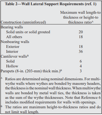
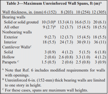
Lateral Support

Lateral support for walls can be provided in the horizontal direction by cross walls, pilasters, buttresses and structural frame members, or in the vertical direction by floor diaphragms, roof diaphragms and structural frame members, as illustrated in Figure 1. For empirically designed walls, such support must be provided at the maximum intervals given in Tables 2 and 3. Note that the span limitations apply to only one direction; that is, the span in one direction may be unlimited as long as the span in the other direction meets the requirements of Tables 2 or 3.

Allowable Stresses

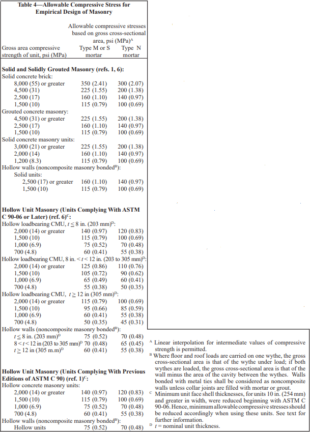
Allowable stresses in empirically designed masonry due to building code prescribed vertical (gravity) dead and live loads (excluding wind or seismic) are given in Table 4.

Table 4 includes two sets of compressive stresses for hollow concrete masonry units (CMU). The first set, titled “Hollow Unit Masonry (Units Complying With ASTM C 90- 06 or Later)” apply to most CMU currently available. The 2006 edition of the CMU specification, Standard Specification for Loadbearing Concrete Masonry Units, ASTM C 90 (ref. 7), included slightly reduced minimum face shell thickness requirements for CMU 10 in. (254 mm) and greater in width. These smaller face shells require a corresponding adjustment to the allowable compressive stresses. The values currently published in the 2006 IBC (“Hollow Unit Masonry (Units Complying With Previous Editions of ASTM C 90)” in Table 4), apply to the previous face shell thicknesses, and should only be used if the CMU to be used have the thicker face shells listed in previous editions of ASTM C 90. This distinction is not applicable to masonry that will be solidly grouted.

Calculated compressive stresses for both single and multiwythe walls are determined by dividing the design load by the gross cross-sectional area of the wall, excluding areas of openings, chases or recesses. The area is based on the specified dimensions of masonry, rather than on nominal dimensions. In multiwythe walls, the allowable stress is determined by the weakest combination of units and mortar shown in Table 4.

In addition, the commentary to Building Code Requirements for Masonry Structures (refs. 6, 8) contains additional guidance for concentrated loads. According to the commentary, when concentrated loads act on empirically designed masonry, the course immediately under the point of bearing should be a solid unit or be filled solid with mortar or grout. Further, when the concentrated load acts on the full wall thickness, the allowable stresses under the load may be increased by 25 percent. The allowable stresses may be increased by 50 percent when concentrated loads act on concentrically placed bearing plates that are greater than one-half but less than the full area.

Anchorage for Lateral Support

Where empirically designed masonry walls depend on cross walls, roof diaphragms, floor diaphragms or structural frames for lateral support, it is essential that the walls be properly anchored so that the imposed loads can be transmitted from the wall to the supporting element. Minimum anchorage requirements for intersecting walls and for floor and roof diaphragms are shown in Figures 2 and 3, respectively.

Masonry walls are required to be anchored to structural frames that provide lateral support by ½ in. (13 mm) diameter bolts spaced at a maximum of 4 ft (1.2 m), or with other bolts and spacings that provide equivalent anchorage. The bolts must be embedded a minimum of 4 in. (102 mm) into the masonry.

In addition, the 2006 IBC requires the designer to check the roof loading for net uplift and, where net uplift occurs, to design the anchorage system to entirely resist the uplift.

Shear Walls

Where the structure depends on masonry walls for lateral stability against wind or earthquake forces, shear walls must be provided parallel to the direction of the lateral forces as well as in a perpendicular plane, for stability.

Requirements for empirically designed masonry shear walls are shown in Figure 4.

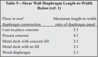
Shear wall spacing is determined empirically by the length-to-width aspect ratio of the diaphragms that transfer lateral forces to the shear walls, as listed in Table 5. In addition, roofs must be designed and constructed in a manner such that they will not impose thrust perpendicular to the shear walls to which they are attached.

The height of empirically designed shear walls is not permitted to exceed 35 ft (10.7 m). The minimum nominal thickness of shear walls is 8 in. (203 mm), except under the 2003 IBC, which allows shear walls of one-story buildings to have a minimum thickness of 6 in. (152 mm).

Bonding of Multiwythe Walls

Wythes of multiwythe masonry walls are required to be bonded together. Bonding can be achieved using masonry headers, metal wall ties, or prefabricated joint reinforcement, as illustrated in Figure 5. Various empirical requirements for each of these bonding methods are given below.

Bonding of solid unit walls with masonry headers.
Where masonry headers are used to bond wythes of solid masonry construction, at least 4 percent of the wall surface of each face must be composed of headers, which must extend at least 3 in. (76 mm) into the backing. The distance between adjacent full-length headers may not exceed 24 in. (610 mm) in either the horizontal or vertical direction. In walls where a single header does not extend through the wall, headers from opposite sides must overlap at least 3 in. (76 mm), or headers from opposite sides must be covered with another header course which overlaps the header below by at least 3 in. (76 mm).

Bonding of hollow unit walls with masonry headers.
Where two or more hollow units are used to make up the thickness of a wall, the stretcher courses must be bonded at vertical intervals not exceeding 34 in. (864 mm) by lapping at least 3 in. (76 mm) over the unit below, or by lapping at vertical intervals not exceeding 17 in. (432 mm) with units that are at least 50 percent greater in thickness than the units below.

Bonding with metal wall ties (other than adjustable ties).
Wire size W2.8 (MW18) wall ties, or metal wire of equivalent stiffness, may be used to bond wythes. Each 4½ ft² (0.42 m²) of wall surface must have at least one tie. Ties must be spaced a maximum of 24 in. (610 mm) vertically and 36 in. (914 mm) horizontally. Hollow masonry walls must use rectangular wall ties for bonding. In other walls, ends of ties must be bent to 90° angles to provide hooks no less than 2 in. (51 mm) long. Additional bonding ties are required at all openings, and must be spaced a maximum of 3 ft (914 mm) apart around the perimeter and located within 12 in. (305 mm) of the opening. Note that wall ties may not include drips, and that corrugated ties may not be used.

Bonding with adjustable ties.
Adjustable ties must be spaced such that there is one tie for each 1.77 ft² (0.164 m²) of wall area, with maximum horizontal and vertical spacings of 16 in. (406 mm). The ties must have a maximum clearance between connecting parts of 1/16 in. (1.6 mm), and, when pintle legs are used, at least two legs with a minimum wire size of W2.8 (MW18). The bed joints of the two wythes may have a maximum vertical offset of no more than 1¼ in. (32 mm). (See Reference 9 for an illustration of these requirements.)

Bonding with prefabricated joint reinforcement.
Where adjacent wythes of masonry are bonded with prefabricated joint reinforcement, there must be at least one cross wire serving as a tie for each 2 ft² (0.25 m²) of wall area. The joint reinforcement must be spaced 24 in. (610 mm) or closer vertically. Cross wires on prefabricated joint reinforcement must be at least wire size W1.7 (MW11) and shall be without drips. The longitudinal wires must be embedded in the mortar.

Change in Wall Thickness

Whenever wall thickness is decreased, at least one course of solid masonry, or special units or other construction, must be placed under the thinner section to ensure load transfer to the thicker section below.

Miscellaneous Empirical Requirements

Following are additional empirical requirements in Building Code Requirements for Masonry Structures. Although not included explicitly in IBC Section 2109, the IBC includes a direct reference to Building Code Requirements for Masonry Structures.

Chases and Recesses
Masonry directly above chases or recesses wider than 12 in. (305 mm) must be supported on lintels.

Lintels
Lintels are designed as reinforced beams, using either the allowable stress design or the strength design provisions of Building Code Requirements for Masonry Structures. End bearing must be at least 4 in. (102 mm), although 8 in. (203 mm) is typical.

Support on Wood
Empirically designed masonry is not permitted to be supported by wood girders or other forms of wood construction, due to expected deformations in wood from deflection and moisture, causing distress in the masonry, and due to potential safety implications in the event of fire.

Corbelling
When corbels are not designed using allowable stress design or strength design, they may be detailed using the empirical requirements shown in Figure 6. Only solid or solidly grouted masonry units may be used for corbelling.

EMPIRICALLY DESIGNED PARTITION WALLS

In many cases, the building structure is designed using traditional engineered methods, such as strength design or allowable stress design, but the interior nonloadbearing masonry walls are empirically designed. In these cases, the partition walls are supported according to the provisions listed in Tables 2 and 3, but it is important that the support conditions provide isolation between the partition walls and the building’s structural elements to prevent the building loads from being transferred into the partition. The anchor, or other support, must provide the required lateral support for the partition wall while also allowing for differential movement. This is in contrast to the “Anchorage for Lateral Support” section, which details anchorage requirements to help ensure adequate load transfer between the building structure and the loadbearing masonry wall.

Figure 7 shows an example of such a support, using clip angles. C channels or adjustable anchors could be used as well. The gap at the top of the wall should be between ½ and 1 in. (13 and 25 mm), or as required to accommodate the anticipated deflection. The gap is filled with compressible filler, mineral wool or a fire-rated material, if required. Fire walls may also require a sealant to be applied at the bottom of the clip angles. This joint should not be filled with mortar, as it may allow load transfer between the structure and the partition wall.

REFERENCES

  1. International Building Code. International Code Council, 2003 and 2006.
  2. Allowable Stress Design of Concrete Masonry Foundation Walls, TEK 15-01B. Concrete Masonry & Hardscapes Association, 2001.
  3. Minimum Design Loads for Buildings and Other Structures, ASCE 7-02. New York, NY: American Society of Civil Engineers, 2002.
  4. Minimum Design Loads for Buildings and Other Structures, ASCE 7-05. New York, NY: American Society of Civil Engineers, 2005.
  5. Masonry Designer’s Guide, 5th Edition. Council for Masonry Research and The Masonry Society, 2007.
  6. Building Code Requirements for Masonry Structures, ACI 530-08/ASCE 5-08/TMS 402-08. Reported by the Masonry Standards Joint Committee, 2008.
  7. Standard Specification for Loadbearing Concrete Masonry Units, ASTM C 90-06. ASTM International, Inc., 2006.
  8. Building Code Requirements for Masonry Structures, ACI 530/ASCE 5/TMS 402. Reported by the Masonry Standards Joint Committee, 2002 and 2005.
  9. Anchors and Ties for Masonry, TEK 12-01B. Concrete Masonry & Hardscapes Association, 2008.
  10. Floor and Roof Connections to Concrete Masonry Walls, TEK 05-07A. Concrete Masonry & Hardscapes Association, 2001.


Design of Anchor Bolts Embedded in Concrete Masonry

INTRODUCTION

The function of anchor bolts is to transfer loads to the masonry from attachments such as ledgers, sills, and bearing plates. Both shear and tension are transferred through anchor bolts to resist design forces such as uplift due to wind at the top of a column or wall or vertical gravity loads on ledgers supporting joists or trusses (see Figure 1). The magnitude of these loads varies significantly with the application.

This TEK summarizes the requirements to properly design, detail and install anchor bolts embedded in concrete masonry construction based on the provisions of the 2013 edition of Building Code Requirements for Masonry Structures (ref. 1). It should be noted that the 2012 editions of the International Building Code and International Residential Code (refs. 3 and 4) reference the provisions of the 2011 edition of Building Code Requirements for Masonry Structures (ref. 5) which contain no significant differences from the following analysis and design methodologies.

Anchor bolt configurations covered by Building Code Requirements for Masonry Structures fall into one of two categories:

• Bent-bar anchors, which include the customary J and L bolts, are threaded steel rods with hooks on the end embedded into the masonry. Bent-bar anchor bolts must meet the material requirements of Standard Specification for Carbon Structural Steel, ASTM A36/A36M (ref. 6).

• Headed anchors include conventional square head or hexhead threaded bolts, but also include plate anchors (where a steel plate is welded to the end of the bolt). Headed anchor bolts must meet the requirements of Standard Specification for Carbon Steel Bolts and Studs, 60,000 psi Tensile Strength, ASTM A307, Grade A (ref. 7).

For other anchor bolt configurations, including post-installed anchors, design loads are determined from testing a minimum of five specimens in accordance with Standard Test Methods for Strength of Anchors in Concrete and Masonry Elements, ASTM E488 (ref. 8) under stresses and conditions that represent the intended use. Allowable stress design values are limited to 20% of the average tested anchor bolt strength. Using strength design provisions, nominal design strengths are limited to 65% of the average tested strength.

GENERAL DESIGN AND DETAILING REQUIREMENTS

Building Code Requirements for Masonry Structures (ref. 1) contains anchor bolt design provisions for both the allowable stress design and strength design methods (Chapters 2 and 3, respectively). An overview of these design philosophies can be found in Allowable Stress Design of Concrete Masonry, TEK 14-07C, and Strength Design Provisions for Concrete Masonry, TEK 14-04B (refs. 9, 10). Note that Chapter 5 of the code also includes prescriptive criteria for floor and roof anchorage that are applicable to empirically designed masonry, but these provisions are not covered here.

While many of the requirements for anchor design vary between the allowable stress and strength design methods, some provisions are commonly shared between the two design approaches. The following discussion and topics apply to anchors designed by either the allowable stress or strength design methods.

Effective Area of Anchor Bolts

For both design methods, the anchor bolt net area used to determine the design values presented in this TEK are taken equal to the following, which account for the reduction in area due to the presence of the anchor threading:

½ in. anchor = 0.142 in.² (91.6 mm²)
⅝ in. anchor = 0.226 in.² (145.8 mm²)
¾ in. anchor = 0.334 in.² (215.4 mm²)
⅞ in. anchor = 0.462 in.² (298.0 mm²)

Effective Embedment Length

The minimum effective embedment length for anchor bolts is four bolt diameters (4db) or 2 in. (51 mm), whichever is greater (see Figure 2). The embedment length of headed bolts, lb, is measured parallel to the bolt axis from the surface of the masonry to the bolt head bearing surface. For bent-bar anchors, the effective embedment length is measured parallel to the bolt axis from the masonry surface to the bearing surface on the bent end minus one anchor bolt diameter.

Placement

Anchor bolts are required to be embedded in grout, with the exception that ¼ in. (6.4 mm) diameter anchors are permitted to be placed in mortar bed joints that are at least ½ in. (12.7 mm) thick. Excluding anchors placed in mortar bed joints, a minimum clearance of ¼ in. (6.4 mm) and ½ in. (12.7 mm) is required between the anchor bolt and the nearest surface of masonry for fine grout and coarse grout, respectively. This requirement applies to anchor bolts embedded in the top of a masonry element as well as those penetrating through the face shells of masonry as illustrated in Figure 2. While research (ref. 11) has shown that placing anchors in oversized holes in masonry unit face shells has no significant impact on the strength or performance of anchors compared to those placed in holes only slightly larger than the anchor diameter, the code has opted to maintain these clearance requirements as a convenient means of verifying that grout has adequately consolidated around the anchor bolt.
Although it rarely controls in typical masonry design, Building Code Requirements for Masonry Structures also requires that the distance between parallel anchors be at least equal to the diameter of the anchor, but not less than 1 in. (25.4 mm) to help ensure adequate anchor performance and grout consolidation around the anchor.

Existing masonry codes do not address tolerances for anchor bolt placement. In the absence of such criteria, construction tolerances used for placement of structural reinforcement could be modified for application to anchor bolts. In order to keep the anchor bolts properly aligned during grout placement, templates can be used to hold the bolts within the necessary tolerances. Templates, which are typically made of wood or steel, also prevent grout leakage in cases where anchors protrude from the side of a wall.

Projected Shear and Tension Areas

The projected tension breakout area, Apt, and the projected shear breakout area, Apv, for headed and bent-bar anchors are determined by Equations 1 and 2 as follows:

The anchor bolt edge distance, lbe, is measured in the direction of the applied load from the center of the anchor bolt to the edge of the masonry. When the projected areas of adjacent anchor bolts overlap, the portion of the overlapping area is reduced by one-half for calculating Apt or Apv as shown in Figure 3. Any portion of the projected area that falls within an open cell, open core, open head joint, or falls outside of the masonry element is deducted from the calculated value of Apt and Apv. A graphical representation of a tension breakout cone is shown in Figure 4.

ALLOWABLE STRESS DESIGN OF ANCHOR BOLTS

Tension

The allowable axial tensile load, Ba, for headed and bent-bar anchor bolts is taken as the smaller of Equation 3, allowable axial tensile load governed by masonry breakout, and Equation 4, allowable axial tensile load governed by anchor yielding. For bent-bar anchors, the allowable axial tensile load must also be less than that determined by Equation 5 for anchor pullout.

Shear

The allowable shear load, Bv, for headed and bent-bar anchor bolts is taken as the smallest of Equation 6, allowable shear load governed by masonry breakout, Equation 7, allowable shear load as governed by crushing of the masonry, Equation 8, allowable shear load as governed by masonry pryout, and Equation 9, allowable shear load as governed by anchor yielding.

Combined Shear and Tension

Anchor bolts subjected to combined axial tension and shear must also satisfy the following unity equation:

The relationship between applied tension and shear loads versus allowable tension and shear loads is illustrated in Figure 5.

STRENGTH DESIGN OF ANCHOR BOLTS

The design provisions for anchor bolts using the strength design method is nearly identical to that used for allowable stress design, with appropriate revisions to convert the requirements to produce nominal axial tension and shear design strengths. The strength reduction factors, Φ, for use in Equations 11 through 18 are taken equal to the following values:

  • when the nominal anchor strength is controlled by masonry breakout, masonry crushing, or anchor pryout, Φ is taken equal to 0.50,
  • when the nominal anchor strength is controlled by anchor bolt yielding, Φ is taken equal to 0.90,
  • when the nominal amchor strength is controlled by anchor pullout, Φ is taken equal to 0.65.

Tension

The nominal axial tensile strength, Ban, for headed and bent-bar anchor bolts is taken as the smaller of Equation 11, nominal axial tensile strength governed by masonry breakout, and Equation 12, nominal axial tensile strength governed by anchor yielding. For bent-bar anchors, the nominal axial tensile strength must also be less than that determined by Equation 13 for anchor pullout.

Shear

The nominal shear strength, Bvn, for headed and bent-bar anchor bolts is taken as the smallest of Equation 14, nominal shear strength governed by masonry breakout, Equation 15, nominal shear strength as governed by crushing of the masonry, Equation 16, nominal shear strength as governed by masonry pryout, and Equation 17, nominal shear strength as governed by anchor yielding.

Combined Shear and Tension

As with allowable stress design, anchor bolts subjected to combined axial tension and shear must also satisfy the following unity equation:

DESIGN EXAMPLE

Two ½ in (12.7 mm) headed anchors comprise a bolted connection for a roof beam to the side of an 8 in. (203mm) masonry wall, see Figure 5 below. The wall has a minimum specified compressive strength, f’m of 2,000 psi (13.8 MPa). The bolts have an effective yield stress of 60 ksi (413.7 MPa) with and effective embedment length and spacing between bolts of 6 in. (50.8 mm).

Allowable Stress Design

It can be assumed that the D + LR is the governing load combination. With this, the total design shear force for the connection is 1,600 lb (7.12 kN), with each anchor bolt resisting half of the total load. As is typical with bolted connections subjected to shear, the load is imparted at an offset distance, e which is equivalent to the additive thickness of the ledger and connector elements. This eccentric load generates a force couple with tensile forces in the anchor and bearing of the masonry wall. Using engineering judgment, the moment arm can be approximated as times the distance from the center line of the bolt to the edge of the ledger, denoted as x for this example. The induced tension force on the entire connection can be calculated as follows:

Using Equation 1, one can determine the area of tensile breakout for each bolt to be 113.10 in² (729.68 cm²), however due to the proximity of the bolts to one another, there is an overlap in projected breakout area. To account for this, one must reduce the projected breakout area by one half of the overlap area when analyzing an individual bolt. The modified projected area for each bolt becomes:

Using the above equation, the modified Apt is found to be 90.99 in² (578.03 cm²).

In turn, the axial tensile strength is controlled by either masonry breakout (Equation 3) or anchor yielding (Equation 4) and determined as follows (Equation 5 is explicitly for bent-bar anchors and need not be checked):

For this example, the axial tensile strength is controlled by the masonry breakout strength, Bab.

Similarly, to determine the allowable shear strength, one would typically calculate the shear breakout area for each anchor. For this particular example, given the direction of shear loading and large edge distance, masonry shear breakout will not be the governing failure mode. Calculated strengths for masonry crushing (Equation 7), anchor pryout (Equation 8), and anchor yielding (Equation 9) are as follows:

In this instance, shear strength of each anchor is controlled by the masonry crushing strength, Bvc.

Checking the combined loading effects for an individual anchor against Equation 10 yields the following:

Because the demand to capacity ratio is less than 1.0, the design is satisfied.

Strength Design

It is assumed that the governing load combination for the connection is 1.2D+1.6LR. With that, the effects of the eccentric shear load are analyzed similarly to the allowable stress design example yielding a factored tensile force of 2,688 lb (11.96 kN) acting on the whole connection. The factored shear load acting on the connection is determined to be 2,240 lb (9.96 kN).

Again, citing Equation 1 and modifying it for the overlap of projected breakout area, Apt for each anchor bolt is found to be 90.99 in.² (578.03 cm²). Refer to the allowable stress design example for clarification.

Axial tensile strength determined by calculating masonry breakout (Equation 11) and anchor yielding (Equation 12) are as follows (as was the case before, Equation 13 need not be checked as this applies only to bent-bar anchors):

The nominal axial tensile strength is governed by the anchor yielding, Bans.

Nominal shear strength is controlled by masonry crushing (Equation 15), anchor pryout (Equation 16), and anchor yielding (Equation 17) and is checked as follows (as explained previously, for this example the wall geometry and direction of loading indicate shear breakout to be an unlikely failure mode):

For this example, the nominal shear strength for each anchor is controlled by masonry crushing, Bvnc.

Applying the appropriate strength reduction factors of Φ = 0.9 for anchor yielding under tensile loads and Φ = 0.5 for masonry crushing under shear loads, and checking the combined loading effects for an individual anchor against Equation 18 yields the following:

With the demand to capacity ratio less than 1.0, the design is satisfied.

ADDITIONAL RESOURCES

A supplemental anchor design spreadsheet (CMU-XLS-002-19, Ref. 12) is available for the design of both face and top mounted masonry anchors in accordance with the 2013 edition of Building Code Requirements for Masonry Structures.

NOTATIONS

Ab          = cross-sectional area of anchor bolt, in.² (mm²)
Apt         = projected area on the masonry surface of a right circular cone for calculating tensile breakout capacity of anchor bolts, in.² (mm²)
Apv        = projected area on the masonry surface of one-half of a right circular cone for calculating shear breakout capacity of anchor bolts, in.² (mm²)
Ba         = allowable axial force on anchor bolt, lb (N)
Bab       = allowable axial tensile load on anchor bolt when governed by masonry breakout, lb (N)
Ban       = nominal axial strength of anchor bolt, lb (N)
Banb     = nominal axial tensile strength of anchor bolt when governed by masonry breakout, lb (N)
Banp     = nominal axial tensile strength of anchor bolt when governed by anchor pullout, lb (N)
Bans      = nominal axial tensile strength of anchor bolt when governed by steel yielding, lb (N)
Bap       = allowable axial tensile load on anchor bolt when governed by anchor pullout, lb (N)
Bas       = allowable axial tensile load on anchor bolt when governed by steel yielding, lb (N)
Bv         = allowable shear force on anchor bolt, lb (N)
Bvb       = allowable shear load on an anchor bolt when governed by masonry breakout, lb (N)
Bvc       = allowable shear load on anchor bolt when governed by masonry crushing, lb (N)
Bvn       = nominal shear strength of anchor bolt, lb (N)
Bvnb     = nominal shear strength of anchor bolt when governed by masonry breakout, lb (N)
Bvnc     = nominal shear strength of anchor bolt when governed by masonry crushing, lb (N)
Bvnpry  = nominal shear strength of anchor bolt when governed by anchor pryout, lb (N)
Bvns     = nominal shear strength of anchor bolt when governed by steel yielding, lb (N)
Bvpry   = allowable shear load on an anchor bolt when governed by anchor pryout, lb (N)
Bvs       = allowable shear load on an anchor bolt when governed by steel yielding, lb (N)
ba        = unfactored axial force on anchor bolt, lb (N)
baf       = factored axial force in anchor bolt, lb (N)
bv        = unfactored shear force on anchor bolt, lb (N)
bvf       = factored shear force in anchor bolt, lb (N)
db        = nominal diameter of anchor bolt, in. (mm)
e          = eccentricity of applied loads on bolted connection, in. (mm)
eb        = projected leg extension of bent bar anchor, measured from inside edge of anchor at bend to farthest point of anchor in the plane of the hook, in. (mm)
f’m       = specified compressive strength of masonry, psi (MPa)
fy         = specified yield strength of steel for anchors, psi (MPa)
lb         = effective embedment length of anchor bolts, in. (mm)
lbe        = anchor bolt edge distance, measured in direction of load, from edge of masonry to center of the cross section of anchor bolt, in. (mm)
s          = spacing between anchors, in. (mm)
x          = depth from center line of anchor to edge of ledger
Φ         = strength reduction factor

REFERENCES

  1. Building Code Requirements for Masonry Structures, TMS 402-13/ACI 530-13/ASCE 5-13, Reported by the Masonry Standards Joint Committee, 2013.
  2. Specification for Masonry Structures, TMS 605-13/ACI 530.1-13/ASCE 6-13, Reported by the Masonry Standards Joint Committee, 2013.
  3. International Building Code, International Code Council, 2012.
  4. International Residential Code, International Code Council, 2012.
  5. Building Code Requirements for Masonry Structures, TMS 402-11/ACI 530-11/ASCE 5-11, Reported by the Masonry Standards Joint Committee, 2011.
  6. Standard Specification for Carbon Structural Steel, ASTM A36-12, ASTM International, 2012.
  7. Standard Specification for Carbon Steel Bolts and Studs, 60,000 psi Tensile Strength, ASTM A307-12, ASTM International, 2012.
  8. Standard Test Methods for Strength of Anchors in Concrete and Masonry Elements, ASTM E488-10, ASTM International, 2010.
  9. Allowable Stress Design of Concrete Masonry, TEK 14-07C, Concrete Masonry & Hardscapes Association, 2011.
  10. Strength Design Provisions for Concrete Masonry, TEK 14-04B, Concrete Masonry & Hardscapes Association, 2008.
  11. Testing of Anchor Bolts in Concrete Block Masonry, Tubbs, J. B., Pollock, D. G., and McLean, D. I., The Masonry Society Journal, 2000.

TEK 12-03C, Revised 2013. CMHA and the companies disseminating this technical information disclaim any and all responsibility and liability for the accuracy and the application of the information contained in this publication.

Integrating Concrete Masonry Walls With Metal Building Systems

INTRODUCTION

Metal buildings are used extensively for warehouses and other structures requiring large, open floor spaces. Part of their design flexibility comes from the ability to clad metal buildings with a variety of materials to provide different appearances or functions to the buildings. Concrete masonry walls are popular enclosure systems for metal buildings because of masonry’s aesthetic appeal, impact resistance, strength, and fire resistance. The durability of concrete masonry resists incidental impacts from hand carts and forklifts, provides maximum protection in disasters such as earthquakes and hurricanes, as well as superior security, fire resistance, and noise control.

Concrete masonry walls used for metal buildings can include: exterior full-height walls, either with or without a parapet; exterior partial-height or wainscot walls; and interior loadbearing walls or nonloadbearing walls or partitions. Architectural concrete masonry units, such as colored, split faced, burnished, or scored units, can be used to provide an almost limitless array of textures and patterns to the walls. These units can be used for the entire facade or for banding courses to achieve specific patterns or highlight certain design aspects of the building.

A more detailed discussion of the system, along with structural design and construction considerations, is included in Concrete Masonry Walls for Metal Building Systems (ref. 1). The manual is intended to
bridge the gap between the engineer who designs the metal building system and the engineer who designs the concrete masonry walls to unify their respective knowledge.

DETAILS

A typical metal building clad with masonry is shown in Figure 1. Figures 2 – 6 show some typical details used for exterior concrete masonry cladding on a metal building. These details may need to be modified to meet individual design conditions.

Because of the inherent material differences between steel and masonry, careful consideration must be given to accommodating differential movement between the two materials and their assemblies. In Serviceability Design Considerations for Low-Rise Buildings (ref. 2), a lateral drift limit of H/100 for a ten year recurrence wind loading based on main wind force resisting system loads is suggested for low rise buildings with exterior masonry walls reinforced vertically. See Table 12.12.1 of ASCE 7 (ref. 3) for the allowable story drift for seismic loading. Most reinforced masonry walls for metal buildings are designed to span vertically, supported by a steel spandrel at the top and by the foundation at the bottom.

WALL BASE

Because of stiffness and deformation incompatibilities between flexible steel and rigid masonry assemblies, and consequently to control the location of cracking in the masonry walls that may result from relatively larger steel frame deflections at the top of the structure, a “hinge” can be incorporated at the base of the masonry assembly to allow out-of-plane rotation.

Two such hinge connections are shown in Figures 2 and 3. The construction shown in Figure 2 uses through-wall flashing to break the bond at the base of the wall providing a simply supported condition allowing shear transfer but no moment for out-of-plane loading. In many cases the shear force can be adequately transferred by friction through the flashed bed joint. However, it is recommended that a positive shear connection be provided by extending foundation dowels across the joint. It is recommended that the number of bars extended across the horizontal joint be minimized, and that the extension be limited to 2 in. (51 mm), to ensure that the joint will behave as assumed. Therefore, every vertical bar otherwise required for strength at critical sections does not necessarily need to be extended through the joint.

Masonry shear walls are very strong and stiff and are often used to resist lateral loads. However, masonry wall sections used as shear wall segments must have vertical reinforcement continuous into the foundation as shown in Figure 3. Flashing is also incorporated at the floor level to allow the wall some out-of-plane rotation due to building drift. Design aids are included in Concrete Masonry Walls for Metal
Building Systems
(ref. 1) for inplane and out-of-plane reinforced masonry walls as well as for lintels and anchor bolts. Appendix C also presents design examples. As shown in Figure 4, these walls normally span vertically and are laterally supported by a spandrel at the top of the masonry portion of the wall.

When the masonry is designed with a base hinge, it is important to properly detail the building corners to accommodate the movements.

A vertical isolation joint should be placed near the building corner and proper consideration should be given to the masonry and steel connections at corner columns. Flexible anchors and/or slotted connections should be used.

WAINSCOT WALLS

Although full height masonry walls provide the most benefit particularly when the masonry is used for shear walls, partial-height walls, or wainscots, are sometimes used. These walls are commonly 4 to 10 ft (1.2 to 3.0 m) high with metal panel walls extending from the top of the masonry to the roof. The masonry provides strength and
impact resistance for the portion of the wall most susceptible to damage.

COLUMN DETAIL

Figure 5 shows the connection of a rigid frame column to concrete masonry sidewalls with a coincident vertical control joint. The details show vertically adjustable column anchors connecting the wall to the column. For walls designed to span vertically, it is good practice to provide a nominal number of anchors connecting the wall to the column to add stiffness and strength to the edge of the wall. If rigid enough, these anchors can assist in laterally bracing the outside column flange. For larger lateral loads, more substantial connections may be required. Anchorage to end wall columns is very similar.

SPANDREL DETAIL

A typical spandrel detail is shown in Figure Spandrels should be placed as high as possible to reduce the masonry span above the spandrel, especially on walls with parapets. Depending on the rigid frame configuration used, rigid frame connection plates and diagonal stiffeners may restrict the spandrel location. The spandrel is designed by the metal building manufacturer. If the inner flange of the spandrel needs to be braced, the metal building manufacturer will show on the drawings where the braces are required along with the information needed for the masonry engineer to design them and their anchorage to the wall.

Shim plates should be used at spandrel/masonry connections to allow for camber in the spandrel and other construction tolerances (see Figure 6). The steel spandrel should never be pulled to the masonry wall by tightening the anchor bolts.

CONSTRUCTION SEQUENCE

Typically, construction of metal buildings with concrete masonry walls proceeds as follows: concrete footing and column placement; concrete masonry foundation wall construction to grade; concrete slab placement; steel erection; and concrete masonry wall construction. Note, however, that this sequence may need to be modified to meet the needs of a particular project. For example, this construction sequence changes when loadbearing end walls are used. In this case, the steel supported by the masonry is erected after the masonry wall is in place.

Coordination between the various trades is essential for efficient construction. Preconstruction conferences are an excellent way for contractors and subcontractors to coordinate construction scheduling and to avoid conflicts and delays.

REFERENCES

  1. Concrete Masonry Walls for Metal Building Systems, CMU-MAN-003-11. Concrete Masonry & Hardscapes Association, Metal Building Manufacturers Association, International Code Council, 2011.
  2. Serviceability Design Considerations for Steel Buildings, AISC Steel Design Guide #3. American Institute of Steel Construction, 2003.
  3. Minimum Design Loads for Buildings and Other Structures, ASCE 7-05. American Society for Civil Engineers, 2005.