Resources

Fasteners for Concrete Masonry

INTRODUCTION

Buildings use a variety of connectors including anchors, wall ties and fasteners. The distinction between the these types of connectors can be confusing. The broad term “connector” is defined as “a mechanical device for securing two or more pieces, parts, or members together, including anchors, wall ties, and fasteners” (refs. 1, 2). While the terms are often used interchangeably even in technical literature and codes, anchors, wall ties and fasteners each have different purposes. Typical industry usage is:

  • anchors secure masonry to its support. Examples are an anchor bolt or a column flange strap anchor used to connect a masonry wythe to a steel column.
  • Ties, such as adjustable wire ties, are used to connect wythes of masonry in a multiwythe wall.
  • Fasteners connect nonmasonry materials or objects to masonry. An example is a toggle bolt used to install a shelf.

This TEK discusses the use of fasteners in concrete masonry assemblies. TEK 12-01B, Anchors and Ties for Masonry (ref. 3) presents information on anchors and wall ties.

TYPES OF FASTENERS

Many fastener types are available. Fasteners for masonry are typically designed to be inset into a mortar joint, penetrate the face shell of a unit into its hollow core, or bore into a solid unit or solidly grouted wall.

Mortared-In Fasteners

Mortared-in refers to bolts not used for structural purposes, threaded rods and other fasteners that are placed in the masonry mortar joints while the wall is being constructed. This eliminates the need to drill or nail into the masonry, but placement must be exact, as these fasteners cannot be moved or adjusted after placement. Although most fasteners are post-applied rather than mortared in, nailer blocks of pressure-treated wood or metal can be installed during wall construction.

Post-Applied Fasteners

Post-applied fasteners fall into three broad categories: hand-driven mechanical or expansion fasteners, power-actuated fastening systems and chemical/adhesive fasteners.

Hand-Driven Mechanical or Expansion Fasteners

Probably the most familiar fasteners are the hand-driven, mechanical or expansion varieties. These fasteners are offered in several types of metal and, in some cases, plastic.

There are many fastener manufacturers and a large array of mechanical and expansion fastener types (see Figure 1). Some of the most common include:

Self-tapping screws (Figure 1a) that cut threads into the concrete masonry unit or mortar joint through a predrilled hole. Most manufacturers produce these in assorted small diameters and in several lengths.

Toggle fasteners (Figure 1b) frequently called toggle bolts come in several configurations but the most common consists of a threaded bolt and a spring-loaded toggle. Once inserted through a predrilled hole into the core of a hollow concrete masonry unit, the toggle expands and bears against the masonry, holding the bolt in place.

Sleeve fasteners (Figure 1c) consist of a threaded stud with a flared cone-shaped end and an expander sleeve assembled over the stud. A washer and nut are then attached to the end of the stud. After insertion, the nut is tightened, drawing the cone-shaped end into the expander sleeve forcing it to expand and bear against the masonry.

Wedge fasteners (Figure 1d) use a nut, washer and a tapered steel stud bolt. This is surrounded by a steel clip or wedges. As the nut is tightened, the stud is drawn up into the clip or wedge, lodging them against the side of the masonry.

Drop-in fasteners (Figure 1e) typically use steel expansion shells and internal plugs which are forced into the shells, causing them to expand against the substrate.

Strike, hit or split-drive fasteners (Figure 1f) rely on a driving or hammering force on a pin, stud or nail to cause the fastener to expand against the concrete masonry unit.

Power-Actuated Fastening Systems

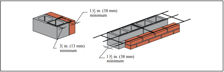
These systems use means such as explosive powder, gas combustion, compressed air or other gas or fuel to embed fasteners into concrete masonry. Of these, powder-actuated systems are most common. Powder-actuated systems use explosive powder to embed the fastener using pressure similar to that of a bullet being fired. The charges used can be more powerful than those in hand guns, so training in the proper use of the tools is critical and in many jurisdictions certification is required. These fastener systems must be fully embedded in masonry (i.e., they cannot extend into hollow areas), so manufacturers recommend that when not used in solid or solid grouted masonry, the concrete masonry face shell thickness be at least 1 ¼ in. (32 mm) thick to accommodate the length of the fastener and withstand the force of the fastener insertion.

When a powder-actuated fastener is driven into concrete masonry, the material around the fastener shank is displaced. This causes the displaced material to compress against the fastener, creating a friction hold. The heat generated during the firing process also causes a sintering, or welding, of the concrete masonry to the fastener (see Figure 2).

There are several types of powder-actuated tools: some shoot the fastener down a barrel while others use pistons to drive the fastener into the wall. The tools are divided into classes according to the velocity of the fastener. The charges also come in a range of power levels.

The fasteners for powder-actuated tools are special heat- treated steel, resulting in a very hard yet ductile fastener, which can penetrate concrete masonry without breaking. The fastener may be threaded or smooth and has a guide to align it in the tool as it is being driven. Fasteners may be packaged in multi-cartridge magazines for rapid repetitive fastening.

Chemical/Adhesive Fasteners

These fastener systems consist of smooth or deformed steel bars or rods placed in a predrilled hole and set with chemical bonding compounds such as epoxies, polyesters, vinylesters or cementitious material (see Figure 3). Loads are transferred from the fastener through the bonding compound to the masonry. Surface-mounted adhesive fasteners are available and are typically used for light-duty conditions such as attaching mirrors and frames to a finished masonry surface. Adhesive fasteners can have some advantages over mechanical expansion fasteners, such as the potential for superior strength, especially pull-out. Adhesive systems may also be more resistant to vibration than mechanical expansion anchors, and the adhesive encapsulates the steel fastener providing additional corrosion protection. Closer edge distances may also be possible with adhesive systems.

DESIGN CONSIDERATIONS AND SELECTION CRITERIA

Because of the variety of fasteners and their applications, fastener design is not addressed in detail in building codes.

Structural Considerations

Structural considerations for fasteners are similar to those for anchors, but the loads on fasteners are typically less. Fastener tension and shear capacities should be considered when selecting a fastener.

Tension is typically transferred from the fastener to the masonry by friction (as for the screw or hit fasteners), keying effects (toggle bolts or expansion systems), bonding (adhesive and chemical systems), or a combination of these mechanisms. Shear is primarily resisted by the fastener itself. As such, shear strength depends on the fastener material and its cross section.

Failure modes for fasteners are also similar to those for anchors and depend on the type of fastener, type of concrete masonry unit, concrete masonry unit compressive strength, depth of embedment, loading conditions, edge distance and fastener load/spacing between fasteners. Typical tension failure modes are fastener breakage, concrete masonry unit cone failure, concrete masonry unit splitting, edge breakouts, pull-out and, in the case of adhesive or chemical fasteners, bond failure. Shear failures include fastener breakage and back pry-out (especially with a group of fasteners or those attached into hollow CMU through the face shell) and edge breakout.

Because fasteners are in most cases proprietary products, it is important to consult the specific manufacturer’s technical data for the fastener being used. Values for pull-out, shear capacity, edge distance and embedment length criteria are given, as well as acceptable substrates and the minimum required concrete masonry unit face shell thickness.

Other Selection Criteria

In addition to the structural requirements, some other basic considerations when selecting a fastener include:

  • the size, especially weight, and configuration of the item being connected to the masonry,
  • whether the fastener will be subject to significant vibration,
  • whether the fastener will be installed in solid or hollow concrete masonry at the attachment point,
  • the minimum edge distance to keep the concrete masonry unit from splitting or spalling,
  • the fastener exposure conditions,
  • whether there is a need for repetitive fastener installation, in which case power-actuated systems offer an advantage,
  • installer qualifications to place adhesive systems or to use powder-actuated fastener tools,
  • restricted access to work areas,
  • power or lighting availability,
  • moisture content of masonry,
  • local availability of fasteners and fastener tools, and
  • other project-specific requirements or conditions.

Codes and Standards

Codes (refs. 1, 2) require that connectors be capable of resisting applied loads and that all pertinent information be included in the project documents. Manufacturer’s literature should be consulted for data pertinent to the fastener and its application. A partial list of national test methods and standards applicable to fasteners includes references 4 through 8.

Corrosion Protection

Specification for Masonry Structures (ref. 9) requires that all metal accessories be stored off the ground and protected from permanent distortions. Since most fasteners include some type of metal, corrosion protection is important. Stainless steel fasteners should conform to ASTM A480, A240 or A580 (refs. 10, 11, 12), as a minimum.

The most common form of corrosion protection for carbon steel fasteners is zinc coating or galvanizing which can be applied in several methods to achieve different coating thicknesses. Table 1 lists minimum corrosion protection requirements (ref. 9).

Galvanic Action

Because fasteners connect nonmasonry items to masonry, the potential for corrosion from galvanic action between the fastener and the item being connected to the masonry must be considered when selecting fasteners.

All metals have electrical potential relative to each other. When metals with different potentials come into contact while in the presence of moisture, the more “active” metal—the one with the more negative potential—corrodes and the other metal is galvanically protected. Table 2 presents the ranking of metals based on their electrical potential from anodic (least noble) to cathodic (most noble). The farther apart two metals are in the table, the more severe and faster the galvanic attack. The relative surface areas of the connecting metals also affect the severity of the galvanic action.

To limit galvanic corrosion, use metals that are close in the galvanic series (Table 2). If this is not possible, separate the dissimilar metals with coatings, gaskets, plastic washers, etc. The fastener should also be selected so that it is the most noble, or protected, component. Drainage is also important to ensure the fastener is not subjected to a continually moist or wet condition.

INSTALLATION

Given the number of fastening options, no one installation method fits all. It is therefore important to follow the specific fastener manufacture’s installation procedures. Some general guidelines include:

  • Place fasteners with proper edge distance and spacing to prevent cracking and spalling of the concrete masonry.
  • Drill holes for insertion anchors the exact diameter specified and to the specified embedment depth.
  • Remove dust from predrilled holes, especially for chemical or adhesive fasteners.
  • For adhesive fasteners, dispense the entire cartridge of adhesive at one time with no interruption in flow.
  • With power-actuated fasteners, use test fastenings to determine the lowest power level that will insert the fastener to the proper depth and position without damaging the concrete masonry.
  • Hold power-actuated tools perpendicular to the masonry surface when firing to avoid ricocheting fasteners.
  • Never fire powder-actuated fasteners into masonry head joints.
  • Store powder loads in separate locked containers away from heat sources. Store the tool unloaded in a locked case.
  • Verify any required installer certification for operation of powder-actuated tools. Sources of information on installation methods include references 17 and 18.
  • Follow all recommended safety procedures.

REFERENCES

  1. International Building Code 2003. International Code Council, 2003.
  2. Building Code Requirements for Masonry Structures, ACI 530-05/ASCE 5-05/TMS 402-05. Reported by the Masonry Standards Joint Committee, 2005.
  3. Anchors and Ties for Masonry, TEK 12-01B. Concrete Masonry & Hardscapes Association, 2011.
  4. Acceptance Criteria for Fasteners Power-Driven into Concrete, Steel and Masonry Elements, ICC Engineering Services Report AC 70 – October 2004. International Code Council Engineering Services Evaluation Committee, Whittier, CA, 2004.
  5. Standard Test Method for Strength of Anchors in Concrete and Masonry Elements, ASTM E488-96 (2003). ASTM International, 2003.
  6. Standard Test Method for Pullout Resistance of Ties and Anchors Embedded in Masonry Mortar Joints, ASTM E754-80 (2000)e1. ASTM International, 2000.
  7. Standard Test Methods for Strength of Power-Actuated Fasteners Installed in Structural Members, ASTM E1190-95 (2000)e1. ASTM International, 2000.
  8. Standard Test Methods for Testing Bond Performance of Bonded Anchors, ASTM E1512-01. ASTM International, 2001.
  9. Specification for Masonry Structures, ACI 530.1-05/ASCE 6-05/TMS 602-05. Reported by the Masonry Standards Joint Committee, 2005.
  10. Standard Specification for General Requirements for Flat-Rolled Stainless and Heat- Resisting Steel Plate, Sheet, and Strip. A480/A480M-05. ASTM International, 2005.
  11. Standard Specification for Chromium and Chromium-Nickel Stainless Steel Plate, Sheet, and Strip for Pressure Vessels and for General Applications. A240/A240M- 05a. ASTM International, 2005.
  12. Standard Specification for Stainless Steel Wire. A580/A580-98(2004). ASTM International, 2004.
  13. Standard Specification for Steel Sheet, Zinc-Coated (Galvanized) or Zinc-Iron Alloy- Coated (Galvannealed) by the Hot-Dip Process, ASTM A653/A653M-05. ASTM International, 2005.
  14. Standard Specification for Zinc Coating (Hot-Dip) on Iron and Steel Hardware, ASTM A153/A153-05. ASTM International, 2005.
  15. Standard Specification for Zinc (Hot-Dip Galvanized) Coatings on Iron and Steel Products, ASTM A123/A123M-02. ASTM International, 2002.
  16. Standard Specification for Steel Wire, Epoxy-Coated, ASTM A899-91(2002). ASTM International, 2002.
  17. PATMI Basic Training Manual, Powder Actuated Tool Manufacturers’ Institute, 2005.
  18. Using Powder Activated (Ammunition) Tools – Study Materials for the Certificate of Fitness Exam for E-21. New York City Fire Department, 2001.


Anchors and Ties for Masonry

INTRODUCTION

Masonry connectors can be classified as wall ties, anchors or fasteners. Wall ties connect one masonry wythe to an adjacent wythe. Anchors connect masonry to a structural support or frame. Fasteners connect an appliance to masonry. This TEK covers metal wall ties and anchors. Fasteners are discussed in TEK 12-05 (ref. 1).

The design of anchors and ties is covered by the International Building Code and Building Code Requirements for Masonry Structures (refs. 2, 3).These provisions require that connectors be designed to resist applied loads and that the type, size and location of connectors be shown or indicated on project drawings. This TEK provides a guide to assist the designer in determining anchor and tie capacity in accordance with the applicable standards and building code requirements.

DESIGN CRITERIA

Connectors play a very important role in providing structural integrity and good serviceability. As a result, when selecting connectors for a project, designers should consider a number of design criteria. Connectors should:

  1. Transmit out-of-plane loads from one wythe of masonry to another or from masonry to its lateral support with a minimum amount of deformation. It is important to reduce the potential for cracking in masonry due to deflection. There is no specific criteria on connector stiffness, but some authorities suggest that a stiffness of 2,000 lb/in. (350 kN/m) is a reasonable target.
  2. Allow differential in-plane movement between two masonry wythes connected with ties. This is especially significant as more insulation is used between the outer and inner wythes of cavity walls and where wythes of dissimilar materials are anchored together. On the surface, it may appear that this criterion is in conflict with Item 1, but it simply means that connectors must be stiff in one direction (out-of-plane) and flexible in the other (in plane). Note that some connectors allow much more movement than unreinforced masonry can tolerate (see ref. 27 for a discussion of potential masonry wall movements). In order to preserve the in-plane and out-of-plane wall tie stiffness, current codes (refs. 2, 3) allow cavity widths up to 4 1/2 in. (114 mm) without performing wall tie analysis. With an engineered analysis of the wall ties, cavity widths may be significantly increased to accommodate thicker insulation.
  3. Meet applicable material requirements:
  • plate and bent-bar anchors—ASTM A36 (ref. 4)
  • sheet-metal anchors and ties—ASTM A1008 (ref. 5)
  • wire anchors and ties—ASTM A82 (ref. 6), and adjustable wire ties must also meet the requirements illustrated in Figure 1
  • wire mesh ties – ASTM A185 (ref. 7)
  1. Provide adequate corrosion protection. Where carbon steel ties and anchors are specified, corrosion protection must be provided by either galvanizing or epoxy coating in conformance with the following (ref. 8):

A. Galvanized coatings:

  • Joint reinforcement in interior walls exposed to a mean relative humidity of 75% or less—ASTM A641 (ref. 13), 0.1 oz zinc/ft2 (0.031 kg zinc/m2)
  • Joint reinforcement, wire ties and wire anchors, exterior walls or interior walls exposed to a mean relative humidity greater than 75%—ASTM A153 (ref. 14), 1.5 oz zinc/ft2 (458 g/m2)
  • Sheet metal ties or anchors, interior walls exposed to a mean relative humidity of 75% or less—ASTM A653 (ref. 15) Coating Designation G60
  • Sheet metal ties or anchors, exterior walls or interior walls exposed to a mean relative humidity greater than 75%—ASTM A153 Class B
  • Steel plates and bars, exterior walls or interior walls exposed to a mean relative humidity greater than 75%—ASTM A123 (ref. 16) or ASTM A153 Class B
  • Plate and bent-bar anchors—ASTM A480 and ASTM A666 (refs. 10, 11)
  • Sheet metal anchors and ties—ASTM A480 and ASTM A240 (refs. 10, 12)
  • Wire ties and anchors—ASTM A580

B. Epoxy coatings:

  • Joint reinforcement—ASTM A884 (ref. 17) Class A
    Type 1 > 7 mils (175 µm)
  • Wire ties and anchors—ASTM A899 (ref. 18) Class C
    20 mils (508 µm)
  • Sheet metal ties and anchors—20 mils (508 µm) per
    surface or per manufacturer’s specification
  • Where stainless steel anchors and ties are specified,
    Specification for Masonry Structures (ref. 8) requires
    that AISI Type 304 or 316 stainless steel be provided
    that complies with:
  • Joint reinforcement—ASTM A580 (ref. 9)
  1. Accommodate construction by being simple in design and easy to install. Connectors should not be so large and cumbersome as to leave insufficient room for mortar in the joints, which can result in a greater tendency to allow water migration into the wall. In the same way, connectors should readily accommodate insulation in wall cavities.

WALL TIE AND ANCHOR REQUIREMENTS

Multiwythe Masonry Wall Types

Wall ties are used in all three types of multiwythe walls (composite, noncomposite and veneer), although some requirements vary slightly depending on the application. The primary differences between these wall systems are in construction details and how the applied loads are assumed to be distributed.

Composite walls are designed so that the masonry wythes act together as a single structural member. This requires the masonry wythes to be connected by masonry headers or by a mortar- or grout filled collar joint and wall ties to help ensure adequate load transfer. TEKs 16-01A and 16-02B (refs. 19, 20) more fully describe composite walls.

In noncomposite masonry (also referred to as a cavity wall), wythes are connected with metal wall ties, but they are designed such that each wythe individually resists the loads imposed on it. Noncomposite walls are discussed in TEKs 16-01A and 16-04A (refs. 19, 21).

In a veneer wall, the backup wythe is designed as the load-resisting system, with the veneer providing the architectural wall finish. Information on veneer walls can be found in TEKs 05-01B and 03 06C (refs. 22, 23). Note that although a cavity wall is defined as a noncomposite masonry wall (ref. 3), the term cavity wall is also commonly used to describe a veneer wall with masonry backup.

Building Code Requirements for Masonry Structures also includes empirical requirements for wire wall ties and strap-type ties used to connect intersecting walls. These requirements are covered in TEK 14-08B (ref. 24).

Wall Ties

Wire wall ties can be either one piece unit ties, adjustable two piece ties, joint reinforcement or prefabricated assemblies made up of joint reinforcement and adjustable ties (see Figure 2). Note that the 2011 edition of Specification for Masonry Structures allows adjustable pintle ties to have only one leg (previously, two legs were required for this type of wall tie).

Wall ties do not have to be engineered unless the nominal width of the wall cavity is greater than 4 1/2 in. (114 mm). These wall tie analyses are becoming more common as a means to accommodate more thermal insulation in the wall cavity. Masonry cavities up to 14 in. (356 mm) have been engineered. Of note for these analyses is that the span of wire is a more critical factor than cavity width, i.e. the span length of the pintel component typically controls the mode of failure.

The prescribed size and spacing is presumed to provide connections that will be adequate for the loading conditions covered by the code. These wall tie spacing requirements can be found in TEK 03-06C (for veneers) and TEK 16-01A (for composite and noncomposite walls). Note that truss-type joint reinforcement is stiffer in the plane of a wall compared to ladder-type, so it is more restrictive of differential movement. For this reason, laddertype joint reinforcement is recommended when significant differential movement is expected between the two wythes or when vertical reinforcement is used. See TEK 12-02B (ref. 25) for more information.

Additional tests are needed for adjustable anchors of different configurations and for one piece anchors. Proprietary anchors are also available. Manufacturers of proprietary anchors should furnish test data to document comparability with industry-tested anchors.

Anchors are usually designed based on their contributory area. This is the traditional approach, but some computer models suggest that this approach does not always reflect the actual behavior of the anchorage system. However, there is currently no accepted computer program to address this point, so most designers still use the contributory area approach with a factor of safety of three. The use of additional anchors near the edges of wall panels is also recommended and required around large openings and within 12 in. (305 mm) of unsupported edges.

CONSTRUCTION

When typical ties and anchors are properly embedded in mortar or grout, mortar pullout or pushout will not usually be the controlling mode of failure. Specification for Masonry Structures requires that connectors be embedded at least 1 1/2 in. (38 mm) into a mortar bed of solid units. The required embedment of unit ties in hollow masonry is such that the tie must extend completely across the hollow units. Proper embedment can be easily attained with the use of prefabricated assemblies of joint reinforcement and unit ties. Because of the magnitude of loads on anchors, it is recommended that they be embedded in filled cores of hollow units. See TEK 03-06C for more detailed information.

REFERENCES

  1. Fasteners for Concrete Masonry, TEK 12-05. Concrete Masonry & Hardscapes Association, 2005.
  2. International Building Code. International Code Council, 2012.
  3. Building Code Requirements for Masonry Structures, TMS 402-11/ACI 530-11/ASCE 5-11. Reported by the Masonry Standards Joint Committee, 2011.
  4. Standard Specification for Carbon Structural Steel, A36-ASTM International, 2008.
  5. Standard Specification for Steel, Sheet, Cold-Rolled, Carbon, Structural, High-Strength Low-Alloy with Improved Formability, A1008-11. ASTM International, 2011.
  6. Standard Specification for Steel Wire, Plain for Concrete Reinforcement, A82-07. ASTM International, 2007.
  7. Standard Specification for Steel Welded Wire Reinforcement, Plain, for Concrete, A185-07. ASTM International, 2007.
  8. Specification for Masonry Structures, TMS 602 -11/ACI 530.1-11/ASCE 6-11. Reported by the Masonry Standards Joint Committee, 2011.
  9. Standard Specification for Stainless Steel Wire, ASTM A580-08. ASTM International, 2008.
  10. Standard Specification for General Requirements for Flat Rolled Stainless and Heat-Resisting Steel Plate, Sheet, and Strip, ASTM A480-11a. ASTM International, 2011.
  11. Standard Specification for Annealed or Cold-Worked Austenitic Stainless Steel, Sheet, Strip, Plate and Flat Bar, ASTM A666-10. ASTM International, 2010.
  12. Standard Specification for Chromium and Chromium Nickel Stainless Steel Plate, Sheet and Strip for Pressure Vessels and for General Applications, ASTM A240-11a. ASTM International, 2011.
  13. Standard Specification for Zinc-Coated (Galvanized) Carbon Steel Wire, ASTM A641-09a. ASTM International, 2009.
  14. Standard Specification for Zinc Coating (Hot-Dip) on Iron and Steel Hardware, ASTM A153-09. ASTM International, 2009.
  15. Standard Specification for Steel Sheet, Zinc-Coated Galvanized or Zinc-Iron Alloy-Coated Galvannealed by the Hot-Dip Process, ASTM A653-10. ASTM International, 2010.
  16. Standard Specification for Zinc (Hot-Dip Galvanized) Coating on Iron and Steel Products, ASTM A123-09. ASTM International, 2009.
  17. Standard Specification for Epoxy-Coated Steel Wire and Welded Wire Fabric for Reinforcement, ASTM A884-06. ASTM International, 2006.
  18. Standard Specification for Steel Wire Epoxy Coated, ASTM A899-91(2007). ASTM International, 2007.
  19. Multiwythe Concrete Masonry Walls, TEK 16-01A, Concrete Masonry & Hardscapes Association, 2005.
  20. Structural Design of Unreinforced Composite Masonry, TEK 16-02B, Concrete Masonry & Hardscapes Association, 2002.
  21. Design of Concrete Masonry Noncomposite (Cavity) Walls, TEK 16-04A, Concrete Masonry & Hardscapes Association, 2004.
  22. Concrete Masonry Veneer Details, TEK 05-01B, Concrete Masonry & Hardscapes Association, 2003.
  23. Concrete Masonry Veneers, TEK 03-06C, Concrete Masonry & Hardscapes Association, 2012.
  24. Empirical Design of Concrete Masonry Walls, TEK 14-08B, Concrete Masonry & Hardscapes Association, 2008.
  25. Joint Reinforcement for Concrete Masonry, TEK 12-02B, Concrete Masonry & Hardscapes Association, 2005.
  26. Porter, Max L., Lehr, Bradley R., Barnes, Bruce A., Attachments for Masonry Structures, Engineering Research Institute, Iowa State University, February 1992.
  27. Crack Control Strategies for Concrete Masonry Construction, CMU-TEC-009-23, Concrete Masonry & Hardscapes Association, 2023.

Concrete Masonry Veneers

INTRODUCTION

In addition to its structural use or as the exterior wythe of composite and noncomposite walls, concrete brick and architectural facing units are also used as veneer over various backing surfaces. The variety of surface textures, colors, and patterns available makes concrete masonry a versatile and popular exterior facing material. Architectural units such as split-face, scored, fluted, ground face, and slump are available in a variety of colors and sizes to complement virtually any architectural style.

VENEER—DESIGN CONSIDERATIONS

Veneer is a nonstructural facing of brick, stone, concrete masonry or other masonry material securely attached to a wall or backing. Veneers provide the exterior wall finish and transfer out-of-plane loads directly to the backing, but they are not considered to add to the load-resisting capacity of the wall system. Backing material may be masonry, concrete, wood studs or steel studs.

There are basically two types of veneer—anchored veneer and adhered veneer. They differ by the method used to attach the veneer to the backing, as illustrated in Figure 1. Unless otherwise noted, veneer requirements are those contained in the International Building Code (IBC) and Building Code Requirements for Masonry Structures (refs. 2, 3).

For the purposes of design, veneer is assumed to support no load other than its own weight. The backing must be designed to support the lateral and in some instances the vertical loads imposed by the veneer in addition to the design loads on the wall, since it is assumed the veneer does not add to the strength of the wall.

Masonry veneers are typically designed using prescriptive code requirements that have been developed based on judgement and successful performance. The prescriptive requirements relate to size and spacing of anchors and methods of attachment, and are described in the following sections. The assembly can be designed as a noncomposite cavity wall where the out-of-plane loads are distributed to the two wythes in proportion to their relative stiffness. Design criteria are provided in IBC Chapter 16 as well as in TEK 16-04A, Design of Concrete Masonry Noncomposite (Cavity) Walls, (ref. 4).

In addition to structural requirements, differential movement between the veneer and its supports must be accommodated. Movement may be caused by temperature changes, moisture-volume changes, or deflection. In concrete masonry, control joints and horizontal joint reinforcement effectively relieve stresses and accommodate small movements. For veneer, control joints should generally be placed in the veneer at the same locations as those in the backing, although recommended control joint spacing can be adjusted up or down based on local experience, the aesthetic requirements of the project, or as required to prevent excessive cracking. See CMU-TEC 009-23, Crack Control for Concrete Brick and Other Concrete Masonry Veneers (ref. 5), for further information.

For exterior veneer, water penetration into the cavity is anticipated. Therefore, the backing system must be designed and detailed to resist water penetration and prevent water from entering the building. Flashing and weeps in the veneer collect any water that penetrates the veneer and redirects it to the exterior. Partially open head joints are one preferred type of weep. They should be at least 1 in. (25 mm) high and spaced not more than 32 in. (813 mm) on center. If necessary, insects can be thwarted by inserting stainless steel wool into the opening or by using proprietary screens. For anchored veneer, open weeps can also serve as vents, allowing air circulation in the cavity to speed the rate of drying. Additional vents may be installed at the tops of walls to further increase air circulation. More detailed information is contained in TEK 05-01B, Concrete Masonry Veneer Details, TEK 19-04A, Flashing Strategies for Concrete Masonry Walls, and TEK 19-05A, Flashing Details for Concrete Masonry Walls (refs. 1, 6, 7).

ANCHORED VENEER

Anchored veneer is veneer which is supported laterally by the backing and supported vertically by the foundation or other structural elements. Anchors are used to secure the veneer and to transfer loads to the backing. Anchors and supports must be noncombustible and corrosion-resistant.

The following prescriptive criteria apply to anchored veneer in areas with velocity pressures, qz, up to 40 psf (1.92 kPa). Modified prescriptive criteria is available for areas with qz greater than 40 psf (1.92 kPa) but not exceeding 55 psf (2.63 kPa) with a building mean roof height up to 60 ft (18.3 m). These modified provisions are presented in the section High Wind Areas. In areas where qz exceeds 55 psf (2.63 kPa), the veneer must be designed using engineering philosophies, and the following prescriptive requirements may not be used.

In areas where seismic activity is a factor, anchored veneer and its attachments must meet additional requirements to assure adequate performance in the event of an earthquake. See the section Seismic Design Categories C and Higher for details.

Masonry units used for anchored veneer must be at least 2 in. (67 mm) thick.

A 1 in. (25 mm) minimum air space must be maintained between the anchored veneer and backing to facilitate drainage. A 1 in. (25 mm) air space is considered appropriate if special precautions are taken to keep the air space clean (such as beveling the mortar bed away from the cavity). Otherwise, a 2 in. (51 mm) air space is preferred. As an alternative, proprietary insulating drainage products can be used.

The maximum distance between the inside face of the veneer and the outside face of the backing is limited to 4 ½ in. (114 mm), except for corrugated anchors used with wood backing, where the maximum distance is 1 in. (25 mm).

When anchored veneer is used as an interior finish supported on wood framing, the veneer weight is limited to 40 lb/ft2 (195 kg/m2).

Deflection Criteria

Deflection of the backing should be considered when using masonry veneer, in order to control crack width in the veneer and provide veneer stability. This is primarily a concern when masonry veneer is used over a wood or steel stud backing. Building Code Requirements for Masonry Structures, however, does not prescribe a deflection limit for the backing. Rather, the commentary presents various recommendations for deflection limits.

For anchored veneer, Chapter 16 of the International Building Code requires a deflection limit of l/240 for exterior walls and interior partitions with masonry veneer.

Support of Anchored Veneer

The height and length of the veneered area is typically not limited by building code requirements. The exception is when anchored veneer is applied over frame construction. For wood stud backup, veneer height is limited to 30 ft (9.14 m) (height at plate) or 38 ft (11.58 m) (height at gable). Similarly, masonry veneer over steel stud backing must be supported by steel shelf angles or other noncombustible construction for each story above the first 30 ft (9.14 m) (height at plate) or 38 ft (11.58 m) (height at gable). This support does not necessarily have to occur at the floor height, for example it can be provided at a window head or other convenient location.

Exterior anchored veneer is permitted to be supported on wood construction under the following conditions:

  • the veneer has an installed weight of 40 psf (195 kg/m2) or less,
  • the veneer has a maximum height of 12 ft (3.7 m),
  • a vertical movement joint in the veneer is used to isolate the veneer supported on wood construction from that supported by the foundation,
  • masonry is designed and constructed so that the masonry is not in direct contact with the wood, and
  • the horizontally spanning member supporting the masonry veneer is designed to limit deflection due to unfactored dead plus live loads to l/600 or 0.3 in. (7.5 mm).

Over openings, the veneer must be supported by non- combustible lintels or supports attached to noncombustible framing, as shown in Figure 2.

The following requirements assume that the veneer is laid in running bond. When other bond patterns are used, the veneer is required to have joint reinforcement spaced no more than 18 in. (457 mm) on center vertically. The joint reinforcement need only be one wire, with a minimum size of W1.7 (MW11).

Anchors

Veneers may generally be anchored to the backing using sheet metal anchors, wire anchors, joint reinforcement or adjustable anchors, although building codes may restrict the use of some anchors. Corrugated sheet metal anchors are permitted with masonry veneer attached to wood backing only. Requirements for the most common anchor types are summarized in Figures 3 through 5 and Table 1. As an alternative, adjustable anchors of equivalent strength and stiffness may be used. Cavity drips are not permitted. See TEK 12-01B, Anchors and Ties for Masonry, (ref. 9) for detailed information on anchor materials and requirements.

Attachment to Backing

When masonry veneer is anchored to wood backing, each anchor is attached to the backing with a corrosion- resistant 8d common nail, or a fastener with equivalent or greater pullout strength. For proper fastening of corrugated sheet metal anchors, the nail or fastener must be located within ½ in. (13 mm) of the 90° bend in the anchor. The exterior sheathing must be either water resistant with taped joints or be protected with a water- resistant membrane, such as building paper ship-lapped a minimum of 6 in. (152 mm) at seams, to protect the backing from any water which may penetrate the veneer.

When masonry veneer is anchored to steel backing, adjustable anchors must be used to attach the veneer. Each anchor is attached with corrosion-resistant screws that have a minimum nominal shank diameter of 0.19 in. (4.8 mm), or an anchor with equivalent pullout strength. Cold-formed steel framing must be corrosion resistant and should have a minimum base metal thickness of 0.043 in. (1.1 mm). Sheathing requirements are the same as those for wood stud backing.

Masonry veneer anchored to masonry backing may be attached using wire anchors, adjustable anchors or joint reinforcement. Veneer anchored to a concrete backing must be attached with adjustable anchors.

Anchor Placement

When typical ties and anchors are properly embedded in mortar or grout, mortar pullout or pushout will not usually be the controlling mode of failure. For this reason, connectors must be embedded at least 1 ½ in. (38 mm) into a mortar bed of solid units, and the mortar bed joint must be at least twice the thickness of the embedded anchor. The required embedment of unit ties in hollow masonry is such that the tie must extend completely across the hollow units (Figure 6). Proper embedment can be easily attained with the use of prefabricated assemblies of joint reinforcement and unit ties. Because of the magnitude of loads on anchors, it is recommended that they be embedded in filled cores of hollow units. To save mortar, screens can be placed under the anchor and 1 to 2 in. (25 to 51 mm) of mortar can be built up into the core of the block above the anchor (Figure 7).

High Wind Areas

In areas with qz greater than 40 psf (1.92 kPa) but not exceeding 55 psf (2.63 kPa) with a building mean roof height up to 60 ft (18.3 m), the following modified prescriptive provisions may be used.

The modified prescriptive provisions are:

  • the maximum wall area supported by each anchor must be reduced to 70% of the value listed in Table 1,
  • anchor spacing is reduced to a maximum of 18 in. (457 mm), both vertically and horizontally, and
  • around openings larger than 16 in. (406 mm) in either direction, anchors must be placed within 12 in. (305 mm) of the opening and spaced at 24 in. (610 mm) on center or less.

In areas where qz exceeds 55 psf (2.63 kPa), the veneer must be designed using engineering philosophies.

Seismic Design Categories C and Higher

To improve veneer performance under seismic loading in Seismic Design Category (SDC) C, the sides and top of the veneer must be isolated from the structure, so that vertical and lateral seismic forces are not transferred to the veneer. This reduces accidental loading and allows more building deflection without causing damage to the veneer.

In SDC D, in addition to this isolation, the maximum wall area supported by each anchor must be reduced to 75% of the value listed in Table 1, although the maximum spacings are unchanged. In addition, when the veneer is anchored to wood backing, the veneer anchor must be attached to the wood using a corrosion-resistant 8d ring-shank nail, a No. 10 corrosion- resistant screw with a minimum nominal shank diameter of 0.190 in. (4.8 mm), or with a fastener having equivalent or greater pullout strength.

In SDC E and F, the requirements listed above for SDC C and D must be met, as well as the additional requirements listed here. The weight of each story of anchored veneer must be supported independently of other stories to help limit the size of potentially damaged areas. In addition, to improve veneer ductility the veneer must have continuous W1.7 (MW11) single wire joint reinforcement at 18 in. (457 mm) o.c. or less vertically, with a mechanical attachment to the anchors, such as clips or hooks.

ADHERED VENEER

Conventional adhered veneer is veneer secured and supported through adhesion with a bonding material applied over a backing that both meets required deflection limits and provides for necessary adhesion. When applied to a masonry or concrete backing, the veneer may be applied directly to the backing substrate using layers of neat cement paste and Type S mortar, as illustrated in Figure 1. When applied over steel or wood framing, the adhered masonry veneer is applied to a metal lath and portland cement plaster backing placed against the sheathing element and attached to the stud framing members.

Alternative design of adhered veneer is permitted under the International Building Code when in compliance with Building Code Requirements for Masonry Structures (MSJC), where the requirements of unit adhesion (shear stress > 50 psi, 345 kPa) are met, out-of-plane curvature of the backing is limited to prevent the veneer from separating from the backing, and freeze thaw cycling, water penetration, and air and water vapor transmission are considered. Although the MSJC does not stipulate a deflection limit to control out-of-plane curvature, the Tile Council of America limits the deflection of backing supporting ceramic tiles to l/360 (ref. 11). Similarly, IBC Chapter 16 (for engineered design) requires a deflection limit of l/360 for exterior walls and interior partitions with plaster or stucco, which would be similar to an adhered veneer application.

Proprietary polymer-fortified adhesive mortars exist that meet the adhesion requirements and are used as a mortar setting bed to adhere the masonry veneers directly to a masonry or concrete backing, or to a lath and plaster backing system over wood or steel studs.

In addition, several proprietary systems are available to aid in placement of adhered masonry veneer on suitable exterior or interior substrates. These typically take the form of galvanized steel support panels that are mechanically anchored to a masonry or concrete backing, or placed against the sheathing element and attached to stud framing members. These products essentially take the place of the metal lath in the adhered veneer application. The metal panels contain support tabs and other features to facilitate the veneer application, carry the dead load of the veneer, and improve bonding of the veneer to the panel. In some cases, metal panel systems provide drainage or air flow channels as well. In lieu of mortar, construction adhesives having a shear bond strength greater than 50 psi (345 kPa) are used to bond the masonry veneer to the panel and masonry pointing mortar is used to fill the joint space between the masonry units. Installation using these products should follow manufacturer’s instructions.

Masonry units used in this application are limited to 2 in. (67 mm) thickness, 36 in. (914 mm) in any face dimension, 5 ft2 (0.46 m2) in total face area and 15 lb/ft2 (73 kg/m2 ) weight. In addition, the International Building Code (ref. 4) stipulates: a minimum thickness of 0.25 in. (6.3 mm) for weather-exposed adhered masonry veneer; and, for adhered masonry veneers 2 used on interior walls, a maximum weight of 20 lb/ft2 (97 kg/ m2).

When an interior adhered veneer is supported by wood construction, the wood supporting member must be designed for a maximum deflection of 1/600 of its span.

Adhered veneer and its backing must also be designed to either:

  • have sufficient bond to withstand a shearing stress of 50 psi (345 kPa) based on the gross unit surface area when tested in accordance with ASTM C482, Standard Test Method for Bond Strength of Ceramic Tile to Portland Cement Paste (ref. 10), or
  • be installed according to the following:
    • A paste of neat portland cement is brushed on the backing and on the back of the veneer unit immediately prior to applying the mortar coat. This neat cement coating provides a good bonding surface for the mortar.
    • Type S mortar is then applied to the backing and to each veneer unit in a layer slightly thicker than in. (9.5 mm). Sufficient mortar should be used so that a slight excess is forced out the edges of the units.
    • The units are then tapped into place to eliminate voids between the units and the backing which could reduce bond. The resulting thickness of mortar between the backing and veneer must be between and ¼ in. (9.5 and 32 mm).
    • Mortar joints are tooled with a round jointer when the mortar is thumbprint hard.

When applied to exterior stud walls, the IBC requires adhered masonry veneer to include a screed or flashing at the foundation. In addition, minimum clearances must be maintained between the bottom of the adhered veneer and paved areas, adjacent walking surfaces and the earth.

Backing materials for adhered veneer must be continuous and moisture-resistant (wood or steel frame backing with adhered veneer must be backed with a solid water repellent sheathing). Backing may be masonry, concrete, metal lath and portland cement plaster applied to masonry, concrete, steel framing or wood framing. Note that care must be taken to limit deflection of the backing, which can cause veneer cracking or loss of adhesion, when adhered masonry veneer is used on steel frame or wood frame backing. The surface of the backing material must be capable of securing and supporting the imposed loads of the veneer. Materials that affect bond, such as dirt, grease, oil, or paint (except portland cement paint) need to be cleaned off the backing surface prior to adhering the veneer.

NOTATIONS:

l = clear span between supports, in. (mm)

qz = velocity pressure evaluated at height z above ground, in.-lb/ft2 (kPa)

REFERENCES

  1. Concrete Masonry Veneer Details, TEK 05-01B. Concrete Masonry & Hardscapes Association, 2003.
  2. 2012 International Building Code. International Code Council, 2012.
  3. Building Code Requirements for Masonry Structures, ACI 530-11/ASCE 5-11/TMS 402-11. Reported by the Masonry Standards Joint Committee, 2011.
  4. Design of Concrete Masonry Noncomposite (Cavity) Walls, TEK 16-04A. Concrete Masonry & Hardscapes Association, 2004.
  5. Crack Control Strategies for Concrete Masonry Construction, CMU-TEC-009-23, Concrete Masonry & Hardscapes Association, 2023.
  6. Flashing Strategies for Concrete Masonry Walls, TEK 1904A. Concrete Masonry & Hardscapes Association, 2008.
  7. Flashing Details for Concrete Masonry Walls, TEK 19-05A. Concrete Masonry & Hardscapes Association, 2008. 
  8. McMican, Donald G. Is Flashing Dangerous Without a Drip? The Aberdeen Group, 1999.
  9. Anchors and Ties for Masonry, TEK 12-01B. Concrete Masonry & Hardscapes Association, 2011.
  10. Standard Test Method for Bond Strength of Ceramic Tile to Portland Cement Paste, ASTM C482-02(2009). ASTM International, 2009.
  11. Handbook for Ceramic Tile Installation. Tile Council of America, 1996.