A wall constructed with two or more wythes of masonry can technically be classified in one of three ways, depending on how each individual wythe is designed and detailed. These three wall systems are composite, noncomposite or veneer walls. A true veneer is nonstructural—any contribution of the veneer to the wall’s out-of plane load resistance is neglected.
Building Code Requirements for Masonry Structures (ref. 1) defines veneer as a masonry wythe which provides the exterior finish of a wall system and transfers out-of-plane loads directly to the backing, but is not considered to add load resisting capacity to the wall system.
Noncomposite walls, on the other hand, are designed such that each wythe individually resists the loads imposed on it. Bending moments (flexure) due to wind or gravity loads are distributed to each wythe in proportion to its relative stiffness.
Composite walls are designed so that the wythes act together as a single member to resist structural loads. This requires that the two masonry wythes be connected by masonry headers or by a mortar or grout filled collar joint and wall ties to help ensure adequate load transfer between the two wythes.
The primary function of anchored veneers is to provide an architectural facade and to prevent water penetration into the building. As such, the structural properties of veneers are neglected in veneer design. The veneer is assumed to transfer out-of-plane loads through the anchors to the backup system. Building Code Requirements for Masonry Structures Chapter 6 (ref. 1) includes requirements for design and detailing anchored masonry veneer.
A masonry veneer with masonry backup and an air space between the masonry wythes is commonly referred to as a cavity wall. The continuous air space, or cavity, provides the wall with excellent resistance to moisture penetration and wind driven rain as well as a convenient location for insulation. This TEK addresses concrete masonry veneer with concrete masonry backup.
DESIGN CONSIDERATIONS
Masonry veneers are typically composed of architectural units such as: concrete or clay facing brick; split, fluted, glazed, ground face or scored block; or stone veneer. Most commonly, anchored masonry veneers have a nominal thickness of 4 in. (102 mm), although 3 in. (76 mm) veneer units may be available as well.
Although structural requirements for veneers are minimal, the following design considerations should be accounted for: crack control in the veneer, including deflection of the backup and any horizontal supports; adequate anchor strength to transfer applied loads; differential movement between the veneer and backup; and water penetration resistance.
The continuous airspace behind the veneer, along with flashing and weeps, must be detailed to collect any moisture that may penetrate the veneer and direct it to the outside. A minimum 1 in. (25 mm) air space between wythes is required (ref. 1), and is considered appropriate if special precautions are taken to keep the air space clean (such as by beveling the mortar bed away from the cavity or by placing a board in the cavity to catch and remove mortar droppings and fins while they are still plastic). Otherwise, a 2 in. (51 mm) air space is preferred. As an alternative, proprietary insulating drainage products can be used.
Although veneer crack control measures are similar to those for other concrete masonry wall constructions, specific crack control recommendations have been developed for concrete masonry veneers. These include: locating control joints to achieve a maximum panel length to height ratio of 11/2 and a maximum spacing of 20 ft (6,100 mm), as well as where stress concentrations occur; incorporating joint reinforcement at 16 in. (406 mm) on center; and using Type N mortar for maximum flexibility. See CMU-TEC-009-23, Crack Control Strategies for Concrete Masonry Construction (ref. 2) for more detailed information.
Because the two wythes in a veneer wall are designed to be relatively independent, crack control measures should be employed as required for each wythe. It is generally not necessary for the vertical movement joints in the veneer wythe to exactly align with those in the backup wythe, provided that the ties allow differential in-plane lateral movement.
Wall ties may be joint reinforcement or wire wall ties. Wall ties for veneers transfer lateral loads to the structural wythe and also allow differential inplane movement between wythes. This second feature is particularly important when the two wythes are of materials with different thermal and moisture expansion characteristics (such as concrete masonry and clay brick), or in an insulated cavity wall which tends to have differential thermal movement between the wythes. When horizontal joint reinforcement is used to tie the two wythes together, hot-dipped ladder type reinforcement is preferred over truss type, because the ladder shape accommodates differential in-plane movement and facilitates placing vertical reinforcement, grout and loose fill insulation. Because veneers rely on the backup for support, wall ties must be placed within 12 in. (305 mm) of control joints and wall openings to ensure the free ends of the veneer are adequately supported. More information on ties for veneers can be found in TEK 03-06C, Concrete Masonry Veneers (ref. 4).
The distance between the inside face of the veneer and the outside face of the masonry backup must be a minimum of 1 in. (25 mm) and a maximum of 4 1/2 in. (114 mm). For glazed masonry veneer, because of their impermeable nature, a 2 in. (51 mm) wide airspace is recommended with air vents at the top and bottom of the wall to enhance drainage and help equalize air pressure between the cavity and the exterior of the wall. Vents can also be installed at the top of other masonry veneer walls to provide natural convective air flow within the cavity to facilitate drying. For vented cavities, it is prudent to create baffles in the cavity at the building corners to isolate the cavities from each other. This helps prevent suction being formed in the leeward cavities.
REFERENCES
Building Code Requirements for Masonry Structures, ACI 530-02/ASCE 5-02/TMS 402-02. Reported by the Masonry Standards Joint Committee, 2002.
CMU-TEC-009-23, Crack Control Strategies for Concrete Masonry Construction, Concrete Masonry and Hardscapes Association, 2023.
TEK 03-06C, Concrete Masonry Veneers, Concrete Masonry and Hardscapes Association, 2012.
The current trend of urban renewal and infill has sparked a high volume of new low-rise masonry residences. These structures come in many forms, but quite often they employ the use of load-bearing concrete masonry walls supporting a wood floor system. These new buildings are largely derivative of the historic load bearing masonry “brownstone” or “three flat” structures of old. This guide is intended to assist contractors and architects to give this building type a modern approach to detailing.
FLOOR SYSTEM CONNECTIONS
When designing low-rise loadbearing structures, the connection detail between the floor system and the wall system is critical for achieving a watertight structure. Much of this TEK will deal with which strategy should be utilized in connecting a wood floor system to a masonry load-bearing wall. Connection methods covered are joist hangers, beam pockets and ledger beam details. Other floor systems are used in low-rise construction that are not addressed here – see 05-07A for further information (ref. 2).
BRICK AND BLOCK COMPOSITE WALL DETAILS
Quite often, the front facade of these structures is composed of brick to give the building a more residential, more human scale. One way to construct a brick and block wall is to separate the two wythes with an airspace, creating a cavity wall. Another is to use a composite wall design. The composite wall consists of an exterior wythe of brick directly mortared or grouted and tied to an inner wythe of CMU. The collar joint between the two wythes should be 100% solid as it is the only defense against water penetration. Minimum tie requirements are one tie per 22/3ft2 of wall area for W1.7 (MW11)(9 gauge) wire or one tie per 41/2ft2 of wall area using W2.8 (MW19)(3/16 in.)wire (ref. 2). A W1.7 (MW11)(9 gauge) joint reinforcement @16 in. (406 mm) on center would meet this requirement and is often used. Details covered for this system are base flashing, window head and window sill details.
EXTERIOR CONCRETE MASONRY
The use of water repellent admixtures in concrete masonry and mortars can greatly reduce the amount of water entering the masonry. In addition, they inhibit any water that penetrates the face from wicking to the back of the wall.
Proper selection and application of integral water repellents and surface treatments can greatly enhance the water resistive properties of masonry, but they should not be considered as substitutes for good fundamental design including flashing details and crack control measures. See TEKs 19-01, 19-02A, and 19-04A (refs. 6, 3, & 5) for more information on water resistant concrete masonry construction.
Because a 4 in. (102 mm) concrete masonry veneer will shrink over time, a 4 in. (102 mm) hot-dipped galvanized ladder type joint reinforcement should be placed in bed joints spaced 16 in. (406 mm) vertically.
Compared to type N or O, type S mortar tends to be less workable in the field and should only be specified when dictated by structural requirements. Sills, copings and chimney caps of solid masonry units, reinforced concrete, stone, or corrosion resistant metal should be used. Copings, sills and chimney caps should project beyond the face of the wall at least 1 in. (25 mm) and should have functional flashing and weep holes.
In addition, all sills, copings and chimney caps should have a minimum slope of 1:4, be mechanically anchored to the wall, and should have properly sized, sealed, and located movement joints when necessary.
Flashing should be installed at locations shown on the plans and in strict accordance with the details and industry standard flashing procedures. Functional, unpunctured flashing and weep holes are to be used at the base of wall above grade, above openings, at shelf angles, lintels, wall-roofing intersections, chimneys, bay windows, and below sills and copings. The flashing should be extended past the face of the wall. The flashing should have end dams at discontinuous ends, and properly sealed splices at laps.
JOIST HANGER DETAILS
The use of a joist hanger system can greatly simplify the bearing detail. The floor system does not interrupt the continuity of the bearing wall. Installation is quicker and easier resulting in a more economical installation.
BEAM POCKET DETAILS
The traditional beam pocket detail still can be effective. Stepped flashing above the bearing line is critical to the performance of this system. Without the flashing, any water present in the wall has an unobstructed path inside the building and has the potential to deteriorate the floor structure.
LEDGER BEAM DETAILS
The use of a ledger beam which is bolted to a bond beam is also a good option for this bearing condition. Through wall flashing is still required to maintain a watertight wall. Any water that penetrates the block with run down the inner cores of the block until it hits the flashing. The flashing and weep holes will allow the water to exit without damaging the structure.
PARAPETS AND WINDOW SILLS
Below are details for a parapet condition and a window sill condition. The parapet is reinforced with No. 4 bars at 48 in. (No.13M @1219 mm) on center or as required for wind resistance. If a metal cap is used, it should extend down the face of the wall at least 3 in. (76 mm) with continuous sealant at the joint on both sides of the wall. The sill detail shows the arrangement of flashing, end dam, weep holes and drip edge and how they all form a watertight
WINDOW HEAD DETAILS
These two window head details show the relationship between the steel lintel, drip edge, flashing, end dams, and weep holes. The first option shows the use of a concrete masonry lintel which is grouted solid and reinforced. The second detail shows two steel lintels used for spanning the opening.
CONTROL JOINT DETAILS
Control joints simply are weakened planes placed at approximately 20 ft. (6 m) on center in concrete masonry walls and at changes in wall elevation/thickness. Notice that the joint reinforcement is discontinuous at the joint. Cores are shown grouted adjacent to the joints as well to ensure structural stability in taller walls and/or high load situations.
COMPOSITE WALL BASE FLASHING DETAILS
Figure 14 shows a stair-stepped flashing detail with the exposed drip edge and weep holes. Figure 15 shows a straight through wall flashing detail. The flashing must be set in mastic on top of the concrete foundation, or the flashing must be self adhesive. The flashing should be turned up on the inner side of the wall to direct water to the outside of the wall.
COMPOSITE WALL WINDOW DETAILS
Here steel lintels back-to-back create the above window span. Stepped flashing turned up on the inside, and folded to form an end dam protects the head condition from moisture. The sill detail also uses flashing, end dams and weep holes to keep moisture out of the wall. The use of a precast concrete or stone sill is highly suggested over using brick rowlock sills.
CONCRETE MASONRY VENEER DETAILING
Figure 18 shows the detailing of a 4 in. (102 mm) concrete masonry veneer used in conjunction with a 8 in. (205 mm) CMU backup wall.
Three types of joint reinforcement are shown including tri-rod, tab and adjustable types. It is imperative that the veneer have a continuous wire embedded in every other course to control movement. With the tri-rod system, the joint reinforcement satisfies this requirement. With the other two systems, an additional ladder type joint reinforcement is used to provide this movement control for the veneer.
REFERENCES
Building Code Requirements for Masonry Structures, ACI 530-05/ASCE 6-05/TMS-402-05. Reported by the Masonry Standards Joint Committee, 2005.
Floor and Roof Connections to Concrete Masonry Walls, TEK 05-07A, Concrete Masonry & Hardscapes Association, 2001.
Design for Dry Single-Wythe Concrete Masonry Walls, TEK 19-02B, Concrete Masonry & Hardscapes Association, 2004.
Flashing Details for Concrete Masonry Walls, TEK 19-05A, Concrete Masonry & Hardscapes Association, 2004.
Flashing Strategies for Concrete Masonry Walls, TEK 19- 04A, Concrete Masonry & Hardscapes Association, 2003.
Water Repellents for Concrete Masonry Walls, TEK 19-01, Concrete Masonry & Hardscapes Association, 2002.
Construction of masonry wall systems is possible without the use of mortar. The use of standard CMU units laid dry and subsequently surface bonded with fiber reinforced surfaced bonding cement has been well documented in the past. (ref. 16) With the use of specially fabricated concrete masonry units known as “dry-stack units,” construction of these mortarless systems is simple, easy and cost effective. This TEK describes the construction and engineering design of such mortarless wall systems.
The provisions of this TEK apply to both specialty units manufactured specifically for dry-stack construction and conventional concrete masonry units with the following system types:
Grouted, partially grouted or surface bonded
Unreinforced, reinforced, or prestressed
Note that dry-stacked prestressed systems are available that do not contain grout or surface bonding. The provisions of this TEK do not apply to such systems due to a difference in design section properties (ref 8).
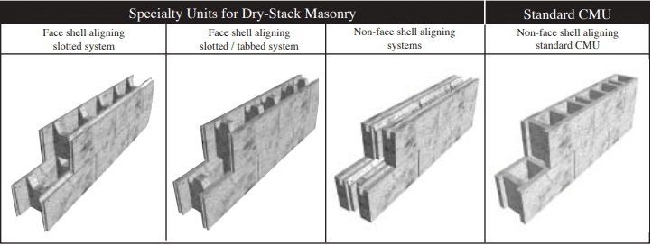
Specially designed units for dry-stack construction are available in many different configurations as shown in Figure 1. The latest and most sophisticated designs incorporate face shell alignment features that make units easier and faster to stack plumb and level. Other units are fabricated with a combination of keys, tabs or slots along both horizontal and vertical faces as shown in Figure 1 so that they may interlock easily when placed. Physical tolerances of dry-stack concrete units are limited to ±1/16 in. (1.58 mm.) which precludes the need for mortaring, grinding of face shell surfaces or shimming to even out courses during construction. Interlocking units placed in running bond resist flexural and shear stresses resulting from out-of-plane loads as a result of the keying action: (a) at the top of a web with the recess in the web of the unit above, (b) at two levels of bearing surface along each face shell at the bed joint, and (c) between adjacent blocks along the head joint. The first of these two interlocking mechanisms also ensures vertical alignment of blocks.
The interlocking features of dry-stack units improve alignment and leveling, reduce the need for skilled labor and reduce construction time. Floor and roof systems can be supported by mortarless walls with a bond beam at the top of the wall which expedites the construction process.
Wall strength and stability are greatly enhanced with grouting which provides the necessary integrity to resist forces applied parallel, and transverse to, the wall plane. Vertical alignment of webs ensures a continuous grout column even when the adjacent cell is left ungrouted. Grouting is necessary to develop flexural tensile stress normal to the bed joints, which is resisted through unit-mortar bond for traditional masonry construction. Strength of grouted dry-stack walls may also be enhanced by traditional reinforcement, prestressing, post-tensioning or with external fiber-reinforced surface coatings (surface bonding) as described in the next section.
Typical applications for mortarless concrete masonry include basement walls, foundation walls, retaining walls, exterior above-grade walls, internal bearing walls and partitions. Dry-stack masonry construction can prove to be a cost-effective solution for residential and low-rise commercial applications because of it’s speed and ease of construction, strength and stability even in zones of moderate and high seismicity. More information on design and construction of dry-stack masonry can be found in Reference 5.
Figure 1–– Dry-Stack Masonry Units
CONSTRUCTION
Dry-stack concrete masonry units can be used to construct walls that are grouted or partially grouted; unreinforced, reinforced or prestressed; or surface bonded. With each construction type, walls are built by first stacking concrete masonry units.
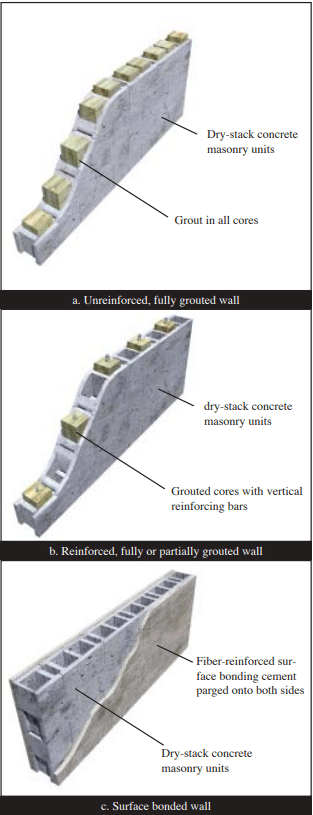
For unreinforced construction as shown in Figure 2a, grouting provides flexural and shear strength to a wall system. Flexural tensile stresses due to out-of-plane bending are resisted by the grout cores. Grout cores also interlace units placed in running bond and thus provide resistance to in-plane shear forces beyond that provided by friction developed along horizontal joints. Grout cores can also be reinforced to increase flexural strength.
Reinforcement can be placed vertically, in which case only those cells containing reinforcement may be grouted as shown in Figure 2b, as well as horizontally, in which case the masonry must be fully grouted. Another version is to place vertical prestressing tendons in place of reinforcement. Vertical axial compressive stress, applied via the tendons, increases flexural and shear capacity. Tendons may be bonded to grout, or unbonded, based upon the design. Placement of grout may be optional. Horizontally reinforced bond beam lintels can be created using a grout stop beneath the unit to contain grout.
As an alternative to reinforcing or prestressing, wall surfaces may be parged (coated) with a fiber-reinforced surface bonding cement/stucco per ASTM C887(ref. 14) as illustrated in Figure 2c. This surface treatment, applied to both faces of a wall, bonds concrete units together without the need for grout or internal reinforcement. The parging material bridges the units and fills the joints between units to provide additional bonding of the coating to the units through keying action. The compressive strength of the parging material should be equal to or greater than that of the masonry units.
Figure 2–– Basic Dry-Stack Masonry Wall Types
Laying of Units
The first course of dry-stack block should be placed on a smooth, level bearing surface of proper size and strength to ensure a plumb and stable wall. Minor roughness and variations in level can be corrected by setting the first course in mortar. Blocks should be laid in running bond such that cells will be aligned vertically.
Grout and Reinforcement
Grout and grouting procedures should be the same as used in conventional masonry construction (ref. 1, 10) except that the grout must have a compressive strength of at least 2600 psi (190 MPa) at 28 days when tested in accordance with ASTM C 1019 (ref.12). Placement of grout can be accomplished in one lift for single-story height walls less than 8 ft (2.43 m). Grout lifts must be consolidated with an internal vibrator with a head size less than 1 in. (25 mm).
Vertical Reinforcing
As for conventional reinforced masonry construction, good construction practice should include placement of reinforcing bars around door and window openings, at the ends, top and bottom of a wall, and between intersecting walls. Well detailed reinforcement such as this can help enhance nonlinear deformation capacity, or ductility, of masonry walls in building systems subjected to earthquake loadings – even for walls designed as unreinforced elements. Additional information on conventional grouting and reinforced masonry wall can be found in TEK 09-04A and TEK 03-03B (refs. 9 & 6).
Pre-stressed Walls
Mortarless walls can also be prestressed by placing vertical tendons through the cores. Tendons can be anchored within the concrete foundation at the base of a wall or in a bottom bond beam and are tensioned from the top of a wall.
Surface Bonded Walls
For walls strengthened with a surface bonding, a thin layer of portland cement surface bonding material should be troweled or sprayed on to a wall surface. The thickness of the surface coating should be at least ⅛ in. (3.2 mm.) or as required by the material supplier.
ENGINEERING PROPERTIES
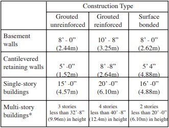
Walls constructed with mortarless masonry can be engineered using conventional engineering principles. Existing building code recommendations such as that produced by the building code (ref. 1) can serve as reference documents, but at the time of this printing it does not address mortarless masonry directly. It is thus considered an alternate engineered construction type. The International Building Code (ref. 7) does list allowable stresses based on gross-cross-sectional area for dry-stacked, surface-bonded concrete masonry walls. These values are the same as presented in TEK 03-05A (ref. 16). Suggested limits on wall or building height are given in Table 1.
Test data (refs. 2, 3 and 4) have shown that the strength of drystack walls exceeds the strength requirements of conventional masonry, and thus the recommended allowable stress design practices of the code can be used in most cases. When designing unreinforced, grouted masonry wall sections, it is important to deduct the thickness of the tension side face shell when determining the section properties for flexural resistance.
Table 1 –– Summary of Wall Heights for 8” (203 mm) Dry-stacked Units (ref. 5)
* Laterally supported at each floor
Unit and Masonry Compressive Strength
Units used for mortarless masonry construction are made of the same concrete mixes as used for conventional masonry units. Thus, compressive strength of typical units could vary between 2000 psi (13.79MPa) and 4000 psi. (27.58 MPa) Standard Methods of Sampling and Testing Concrete Masonry Units (ref. 11) can be referred to for determining strength of dry-stack units.
Masonry compressive strength f’m can conservatively be based on the unit-strength method of the building code (ref . 15), or be determined by testing prisms in accordance with ASTM C1314 (ref. 4). Test prisms can be either grouted or ungrouted depending on the type of wall construction specified.
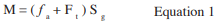
Because no mortar is used to resist flexural tension as for conventional masonry construction, flexural strength of mortarless masonry is developed through the grout, reinforcement or surface coating. For out-of-plane bending of solid grouted walls allowable flexural strength can be estimated based on flexural tensile strength of the grout per Equation 1.
Consideration should be given to the reduction in wall thickness at the bed joints when estimating geometrical properties of the net effective section.
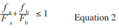
Correspondingly, flexural strength based on masonry compressive stress should be checked, particularly for walls resisting significant gravity loads, using the unity equation as given below.
Buckling should also be checked. (Ref. 8)
In-Plane Shear Strength
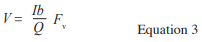
Shear strength for out-of-plane bending is usually not a concern since flexural strength governs design for this case. For resistance to horizontal forces applied parallel to the plane of a wall, Equation 3 may be used to estimate allowable shear strength.
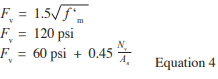
Fv is the allowable shear strength by the lesser of the three values given in Equation 4.
Grouted, Reinforced Construction
Mortarless masonry that is grouted and reinforced behaves much the same as for conventional reinforced and mortared construction. Because masonry tensile strength is neglected for mortared, reinforced construction, flexural mechanisms are essentially the same with or without the bed joints being mortared provided that the units subjected to compressive stress are in good contact. Thus, allowable stress design values can be determined using the same assumptions and requirements of the MSJC code. (ref.1)
Axial and flexural tensile stresses are assumed to be resisted entirely by the reinforcement. Strains in reinforcement and masonry compressive strains are assumed to vary linearly with their distance from the neutral axis. Stresses in reinforcement and masonry compressive stresses are assumed to vary linearly with strains. For purposes of estimating allowable flexural strengths, full bonding of reinforcement to grout are assumed such that strains in reinforcement are identical to those in the adjacent grout.
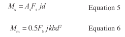
For out-of-plane loading where a single layer of vertical reinforcement is placed, allowable flexural strength can be estimated using the equations for conventional reinforcement with the lower value given by Equations 5 or 6.
In-Plane Shear Strength
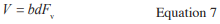
Though the MSJC code recognizes reinforced masonry shear walls with no shear, or horizontal reinforcement, it is recommended that mortarless walls be rein- forced with both vertical and horizontal bars. In such case, allowable shear strength can be determined based on shear reinforcement provisions (ref. 1) with Equations 7, 8 and 9.
Where Fv is the masonry allowable shear stress per Equations 8 or 9.
Solid Grouted, Prestressed Construction
Mortarless masonry walls that are grouted and pre- stressed can be designed as unreinforced walls with the prestressing force acting to increase the vertical compres- sive stress. Grout can be used to increase the effective area of the wall. Flexural strength will be increased because of the increase in the fa term in Equation 1. Shear strength will be increased by the Nv term in Equation 4.
Because the prestressing force is a sustained force, creep effects must be considered in the masonry. Research on the long-term behavior of dry-stacked masonry by Marzahn and Konig (ref. 8) has shown that creep effects may be accentuated for mortarless masonry as a result of stress concentrations at the contact points of adjacent courses. Due to the roughness of the unit surfaces, high stress concentrations can result which can lead to higher non-proportional creep deformations. Thus, the creep coefficient was found to be dependent on the degree of roughness along bed-joint surfaces and the level of applied stress. As a result, larger losses in prestressing force is probable for dry-stack masonry.
Surface-Bonded Construction
Dry-stack walls with surface bonding develop their strength through the tensile strength of small fiberglass fibers in the 1/8” (3.8mm) thick troweled or surface bonded cement-plaster coating ASTM C-887(Ref. 14). Because no grouting is necessary, flexural tension and shear strength are developed through tensile resistance of fiberglass fibers applied to both surfaces of a wall. Test data has shown that surface bonding can result in a net flexural tension strength on the order of 300 psi.(2.07 MPa) Flexural capacity, based on this value, exceeds that for conventional, unreinforced mortared masonry construction, therefore it is considered conservative to apply the desired values of the code (ref. 1) for allowable flexural capacity for portland cement / lime type M for the full thickness of the face shell.
Out-of-Plane and In-Plane Flexural Strength
Surface-bonded walls can be considered as unreinforced and ungrouted walls with a net allowable flexural tensile strength based on the strength of the fiber-reinforcement. Flexural strength is developed by the face shells bonded by the mesh. Allowable flexural strength can be determined using Equation 1 with an Ft value determined on the basis of tests provided by the surface bonding cement supplier. Axial and flexural compressive stresses must also be checked per Equation 2 considering again only the face shells to resist stress.
Surface Bonded In-Plane Shear Strength
In-plane shear strength of surface-bonded walls is attributable to friction developed along the bed joints resulting from vertical compressive stress in addition to the diagonal tension strength of the fiber coating. If the enhancement in shear strength given by the fiber reinforced surface parging is equal to or greater than that provided by the mortar-unit bond in conventional masonry construction, then allowable shear strength values per the MSJC code (ref. 1) may be used. In such case, section properties used in Equation 3 should be based on the cross-section of the face shells.
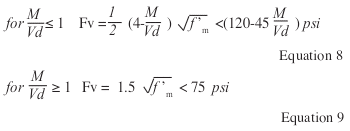
Figure 3 – A Mortarless Garden Wall Application
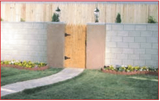
Figure 4 – A Residential, Mortarless, Single-Family Basement – Part of a 520 Home Development
REFERENCES
Building Code Requirements for Masonry Structures), ACI 530-02/ ASCE 5-02/TMS 402-02. Reported by the Masonry Standards Joint Committee (MSJC), 2002.
Drysdale, R.G., Properties of Dry-Stack Block, Windsor, Ontario, July 1999.
Drysdale, R.G., Properties of Surface-Bonded Dry-Stack Block Construction, Windsor, Ontario, January 2000.
Drysdale, R.G., Racking Tests of Dry-Stack Block, Windsor, Ontario, October 2000.
Drysdale, R.G., Design and Construction Guide for Azar Dry-Stack Block Construction, JNE Consulting, Ltd., February 2001.
Grout for Concrete Masonry, TEK 09-04A, Concrete Masonry & Hardscapes Association, 2002.
2000 International Building Code, Falls Church, VA. International Code Council, 2000.
Marzahn, G. and G. Konig, Experimental Investigation of Long-Term Behavior of Dry-Stacked Masonry, Journal of The Masonry Society, December 2002, pp. 9-21.
Hybrid Concrete Masonry Construction Details, TEK 0303B. Concrete Masonry & Hardscapes Association, 2009.
Specification for Masonry Structures, ACI 530.1-02/ASCE 6-02/ TMS 602-02. Reported by the Masonry Standards Joint Committee (MSJC), 2002.
Standard Methods of Sampling and Testing Concrete Masonry Units, ASTM C140-02a, ASTM International, Inc. , Philadelphia, 2002.
Standard Method of Sampling and Testing Grout, ASTM C1019-02, ASTM International, Inc., Philadelphia, 2002.
Standard Specification for Grout for Masonry, ASTM C 476-02. ASTM International, Inc., 2002
Standard Specification for Packaged, Dry, Combined Materials for Surface Bonding Mortar, ASTM C 887-79a (2001). ASTM International, Inc., 2001.
Standard Test Method for Compressive Strength of Masonry Assem blages, ASTM C1314-02a, ASTM International, Inc., Philadelphia, 2002.
An net cross-sectional area of masonry, in² (mm²) As effective cross-sectional area of reinforcement, in2 (mm2) b width of section, in. (mm) d distance from extreme compression fiber centroid of tension reinforcement, in. (mm) Fa allowable compressive stress due to axial load only, psi (MPa) Fb allowable compressive stress due to ß exure only, psi (MPa) Fs allowable tensile or compressive stress in reinforcement, psi (MPa) Ft flexural tensile strength of the grout, psi(MPa) Fv allowable shear stress in masonry psi (MPa) fa calculated vertical compressive stress due to axial load, psi (MPa) fb calculated compressive stress in masonry due to ß exure only, psi (MPa) f’ specified compressive strength of masonry, psi (MPa) I moment of inertia in.4 (mm4) j ratio of distance between centroid of flexural compressive forces and centroid of tensile forces to depth, d k ratio of the distance between compression face of the wall and neu tral axis to the effective depth d M maximum moment at the section under consideration, in.-lb (N-mm) Nv compressive force acting normal to the shear surface, lb (N) Q first moment about the neutral axis of a section of that portion of the cross section lying between the neutral axis and extreme fiber in.³ (mm³) Sg section modulus of uncracked net section in.³ (mm³) V shear force, lb (N)
High winds subject buildings to large horizontal forces as well as to significant uplift. Reinforced concrete masonry is well suited to resist the large uplift and overturning forces due to its relatively large mass.
High wind provisions generally apply to areas where the design wind speed is over 100 mph (161 km/hr) and over three second gust as defined by ASCE 7 (ref. 10). The enclosed details represent prescriptive minimum requirements for concrete masonry buildings, based on Standard for Hurricane Resistant Residential Construction (ref. 3).
CONTINUOUS LOAD PATH
Connections between individual building elements—roof, walls, floors and foundation—are critical to maintaining structural continuity during a high wind event. The critical damage to buildings in such events typically occurs due to uplift on the roof, resulting in the loss of crucial diaphragm support at the top of the wall. A primary goal for buildings subjected to high winds is to maintain a continuous load path from the roof to the foundation. This allows wind uplift forces on the roof to be safely distributed through the walls to the foundation. If one part of the load path fails or is discontinuous, building failure may occur.
Proper detailing and installation of mechanical connectors is necessary for maintaining continuous load paths. Note that in order for connectors to provide their rated load capacity, they must be installed according to the manufacturer’s or building code specifications. In coastal areas, corrosion protection is especially important due to the corrosive environment. Note that water penetration details are not specifically highlighted in the following details. The reader is referred to references 7 through 9 for more information on preventing water penetration in concrete masonry walls. In addition to a continuously reinforced bond beam at the top of the wall around the entire perimeter of the building, vertical reinforcement must be placed throughout a wall to resist the high uplift loads and provide continuity, including: at corners and wall intersections; on each side of openings wider than 6 ft (1,829 mm); at the ends of shear segments; and where girders or girder trusses bear on the concrete masonry wall (refs. 3, 4). Each of the exterior walls on all four sides of the building and all interior walls designed as shear walls must have at least one 2 ft (610 mm) minimum section of wall identified as a shear segment to resist the high lateral loads. Longer shear segments are more effective and are recommended where possible or required by design. See Figure 1 for a summary of reinforcement requirements (ref. 3).
Reinforcement must be properly spliced to provide load path continuity. Using allowable stress design, a splice length of 40 bar diameters is required by Building Code Requirements for Masonry Structures (ref. 1) for Grade 40 reinforcement and 48 bar diameters for Grade 60 reinforcement. If the wall was designed assuming Grade 40 and Grade 60 was used for construction, however, the 40 bar diameter lap splice may still be used. See Steel Reinforcement for Concrete Masonry, TEK 12-04D (ref. 5) for standard hook requirements.
DETAILS
Exterior Loadbearing Wall
Figure 2 shows a typical loadbearing wall with a floating floor slab. Vertical reinforcement should be placed in the center of the concrete masonry cores to adequately resist both positive and negative wind pressures. Bond beam depth and minimum horizontal reinforcement varies with design wind velocity, ceiling height, roof truss span and spacing of vertical wall reinforcement. Since wind suction forces on the leeward side of a building can be essentially as high as the pressure forces on the windward side, limitations are placed on the height above grade. However, if the slab is laterally supported and tied to the concrete masonry foundation wall as shown in Figure 3, the foundation wall may be extended to 8 ft (2,440 mm) above grade (ref. 3).
Roof Truss Anchor
Figure 4 shows a typical roof truss anchor cast into the bond beam of a concrete masonry bearing wall. The required anchor load capacity depends on the design wind speed as well as the roof truss span. In addition to being rated for uplift, the anchor must be rated for horizontal forces parallel to the wall (in-plane) and perpendicular to the wall (out-of-plane).
Often, the direct embedded roof truss anchor method of connecting the roof to walls is preferred over the bolted top plate and hurricane clip method, as it generally has greater capacity and fewer connections. Additionally, the nail area available for the hurricane clip is limited by the thickness of the top plate.
Bolted Top Plate
As an alternate to the roof truss anchor, a bolted top plate may be used for the roof to wall connection (see Figure 5); however, anchor bolt spacing must be reduced (24 in. (610 mm) maximum) because the top plate is loaded in its weak direction. The detail illustrates several different connector types that are commonly used to connect the truss to the top plate.
Gable End Walls
Because of their exposure, gable end walls are more prone to damage than are hipped roofs unless the joint at the top of the end wall and the bottom of the gable (see Figure 6b) is laterally supported for both inward and outward forces. Figure 6a shows a continuous masonry gable end wall using either a raked concrete bond beam or a cut masonry bond beam along the top of full height reinforced concrete masonry gable end walls.
As an alternative, a braced gable end wall can be constructed as shown in Figure 6b by stopping the masonry of the gable end at the eave height and then using conventional wood framing to the roof diaphragm. However, unless the end wall is properly braced to provide the necessary lateral support as shown in Figure 6b, this results in a weak point at the juncture of the two materials with little capacity to resist the high lateral loads produced by high winds. The number and spacing of braces depends on design wind speed, roof slope and roof span (ref. 2, 3, 6).
Gable End Wall Overhangs
Figure 7a shows a continuously reinforced castin-place concrete rake beam along the top of the gable end wall. The beam is formed over uncut block in courses successively shortened to match the slope of the roof. A minimum of 4 in. (102 mm) is needed from the highest projected corner of block to the top of the beam. Reinforcement that is continuous with the bond beam reinforcement in the side walls is placed in the top of the beam. In this detail, an outlooker type overhang is shown where the rake beam is constructed 3½ in. (89 mm) lower than the trusses so that a pressure treated 2 x 4 (38 x 89 mm) can pass over it. A ladder type overhang detail also can be used with the concrete rake beam where the beam is constructed to the same height as the trusses similar to that shown for the cut masonry rake beam in Figure 7b.
Figure 7b shows a continuously reinforced cut masonry rake beam along the top of the gable end wall. Masonry units are cut to conform to the roof slope at the same height as the roof trusses. A 2 ¾ in. (70 mm) deep notch is cut into the tops of the concrete masonry webs to allow placement of reinforcement that is continuous with the bond beam reinforcement in the side walls. A minimum of height of 4 in. (102 mm) is needed for the cut masonry bond beam. In this figure, a ladder type overhang is shown. However, an outlooker type overhang detail can be used similar to that shown for the cast-in-place concrete rake beam in Figure 7a.
REFERENCES
Building Code Requirements for Masonry Structures, ACI 530-02/ASCE 5-02/TMS 402-02. Reported by the Masonry Standards Joint Committee, 2002.
The Guide to Concrete Masonry Residential Construction in High Wind Areas. Florida Concrete & Products Association, Inc., 1997.
Standard for Hurricane Resistant Residential Construction, SSTD 10-99. Southern Building Code Congress International, Inc., 1999.
2000 International Building Code. International Code Council, 2000.
Steel Reinforcement for Concrete Masonry, TEK 12-04D. Concrete Masonry & Hardscapes Association, 2002.
Annotated Design and Construction Details for Concrete Masonry, CMU-MAN-001-23. Concrete Masonry & Hardscapes Association, 2003.
Design for Dry Single-Wythe Concrete Masonry Walls, TEK 19-02B. Concrete Masonry & Hardscapes Association, 2012.
Flashing Strategies for Concrete Masonry Walls, TEK 19- 04A. Concrete Masonry & Hardscapes Association, 2003.
Flashing Details for Concrete Masonry Walls, TEK 19-05A. Concrete Masonry & Hardscapes Association, 2008.
Minimum Design Loads for Buildings and Other Structures, ASCE 7-02. American Society of Civil Engineers, 2002.
A building’s corners are typically constructed first, then the remaining wall section is filled in. Because they guide the construction of the rest of the wall, building the corners requires special care. It is essential that the corner be built as shown on the foundation or floor plan to maintain modular dimensions.
For maximum construction efficiency and economy, concrete masonry elements should be designed and constructed with modular coordination in mind. Corners, however, present unique situations, because the actual widths of standard units are 3 5/8, 5 5/8, 7 5/8, 9 5/8 and 11 5/8 in. (92, 143, 194, 244 and 295 mm). In order to maintain an 8-in. (203-mm) module, special corner details have been developed to accommodate most typical situations.
Figures 2 through 6 show how corners can be constructed to minimize cutting of units while maintaining modularity of the construction. Vertical steel, while not always required, is often used at corner intersections.
UNITS
Unlike stretcher units, units used in corner construction have square ends (see Figure 1). In addition, all-purpose or kerf units are available, with two closely spaced webs in the center that allow the unit to be easily split on the jobsite, facilitating corner construction. Other special units may also be available, such as bevelled-end units, forming a 45° angle with the face of the unit, which are used to form walls intersecting at 135° angles. Units in adjacent courses overlap to form a running bond pattern at the corner. Architectural units, such as those with split or scored faces, are often available with the architectural finish on two sides to accommodate corner construction.
Local manufacturers should be contacted for information on unit availability.
CODE PROVISIONS FOR INTERSECTING WALLS
Building Code Requirements for Masonry Structures (ref. 3) stipulates three options to transfer stresses from one wall to another at wall intersections, each requiring the masonry to be laid in running bond. These three options are via: running bond; steel connectors; and bond beams. Corner construction lends itself to providing shear transfer by relying on running bond.
Running bond (defined as the placement of masonry units such that head joints in successive courses are horizontally offset at least one quarter the unit length) ensures there is sufficient unit interlock at the corner to transfer shear. When any of these conditions are not met, the transfer of shear forces between walls is required to be prevented.
REFERENCES
Annotated Design and Construction Details for Concrete Masonry, CMU-MAN-001-03, Concrete Masonry & Hardscapes Association, 2003.
Reinforced Concrete Masonry Inspector’s Handbook, 4th edition. Masonry Institute of America, 2002.
Building Code Requirements for Masonry Structures, ACI 530 02/ASCE 5-02/TMS 402-02. Reported by the Masonry Standards Joint Committee, 2002.
Concrete masonry, due to its inherent durability, reliability and superior fire resistance characteristics, is well suited to a range of fire protection applications.
The International Building Code (IBC) (ref. 1) defines three wall types for fire protection— fire wall, fire barrier and fire partition—depending on the level of protection provided for the type of occupancy and intended use. Of the three defined fire-rated assemblies, a fire wall is generally considered to provide the highest level of robustness and fire safety. As such, it is intended to provide complete separation and must be structurally stable under fire conditions.
Generally, fire barriers and fire partitions are required to provide the minimum protection necessary to assure that building occupants can evacuate a structure without suffering personal injury or loss of life. In addition to these requirements, fire walls reduce the likelihood of fire spread into the adjoining space, thus minimizing major property loss. Potentially significant architectural and economic advantages can be gained from using fire walls since each portion of a building separated by fire walls is considered a separate building for code compliance purposes.
Designing and detailing fire walls is a complex task with many facets, including structural criteria, fire resistance, vertical and horizontal continuity, and criteria for protecting openings and joints. It is beyond the scope of this TEK to include every code provision and exception for fire wall design for all project conditions. While much of the information in this TEK is applicable to both the IBC and the NFPA 5000 (ref. 2) building codes, the provisions are based on the 2003 IBC, so certain provisions may be different from NFPA 5000 requirements. Hence, the information may or may not conform to local building code requirements and should be carefully reviewed to ensure compliance. In addition, the details shown here are not the only ones that will comply, but are included as examples. Project specific needs will dictate the final detailing decisions.
FIRE WALLS
By Code (ref. 1), fire walls are required to have the minimum fire-resistance rating acceptable for the particular occupancy or use group which they separate and must also have protected openings and penetrations. A fire wall must have both vertical and horizontal continuity to ensure that the fire does not travel over, under or around the fire wall. In addition, the wall must have sufficient structural stability under fire conditions to remain standing for the duration of time indicated by the fire-resistance rating even with the collapse of construction on either side of the fire wall.
Fire-Resistance Rating
Because fire walls provide a complete separation between adjoining spaces, each portion of the structure separated by fire walls is considered to be a separate building. Fire walls in all but Type V construction must be constructed of approved noncombustible materials. Table 1 shows minimum required fire-resistance ratings. Information on determining the fire-resistance ratings of concrete masonry assemblies is contained in Fire Resistance Rating of Concrete Masonry Assemblies, TEK 07-01D and Standard Method for Determining Fire Resistance of Concrete and Masonry Construction Assemblies (refs. 3, 4).
Protected Openings and Penetrations
The IBC states that fire walls must have closures such as fire doors or shutters which automatically activate to secure the opening in the event of a fire. Further, openings in fire walls are restricted to a maximum size of 120 ft2 (11.2 m2). An exception permits larger openings provided both buildings separated by the fire wall are equipped throughout with automatic sprinkler systems. In all cases, the aggregate width of all openings at any floor level is limited to 25 percent of the wall length.
Through-penetrations in fire walls must utilize either fire-resistance rated assemblies or a firestop system which is tested in accordance with either ASTM E 814 (ref. 5) or UL 1479 (ref. 6). The annular space between steel, iron or copper pipes or steel conduits and surrounding concrete masonry fire walls may be filled with concrete, grout or mortar for the thickness required to provide a fire-resistance rating equivalent to the fire-resistance rating of the wall penetrated. In addition, the penetrating item is limited to a 6-in. (152-mm) nominal diameter and the opening is limited to 144 in.2 (92,900 mm2). Openings for steel electrical outlet boxes are permitted provided they meet the Code specified requirements.
Combustible members, such as wood, are permitted to be framed into concrete masonry fire walls provided that, when framed on both sides of the wall, there is at least 4 in. (102 mm) between the embedded ends of the wood framing. The full thickness of the fire wall 4 in. (102mm) above and below, as well as in between, the combustible member must be filled with noncombustible materials approved for fireblocking.
Voids created at the junction of walls and floor/ceiling/ roof assemblies must be protected from fire passage by using fireresistant joint systems tested in accordance with ASTM E 1966 or UL 2079 (refs. 7, 8). Control joints in fire walls must have fire-resistance ratings equal to or exceeding the required rating of the wall. Recommendations for locating and spacing control joints in concrete masonry walls also apply to concrete masonry fire walls. Crack Control Strategies for Concrete Masonry Construction, CMU-TEC 009-23 (ref. 9) includes control joint spacing criteria and illustrates control joint details for various fire-resistance ratings.
Vertical and Horizontal Continuity
The IBC mandates vertical continuity of a fire wall by requiring that the wall extend continuously from the foundation to a termination point at least 30 in. (762 mm) above both adjacent roofs. Exceptions permitting the fire wall termination at the underside of the roof deck or slab are listed in the Code. These exceptions require the use of Class B roof coverings (minimum), no openings within 4 ft (1.22 m) of the fire wall and other criteria for roof assembly protection. Buildings located over parking garages and stepped buildings are subject to additional requirements and permitted exceptions.
Horizontal continuity limits the spread of fire around the ends of a fire wall. The IBC requires that fire walls be continuous from exterior wall to exterior wall and that they extend at least 18 in. (457 mm) beyond the exterior surface of exterior walls. As with the vertical continuity requirements, there are criteria for terminating the fire wall at the interior surface of an exterior wall based on the types and fire resistance ratings of the intersecting wall constructions and on the presence of an automatic sprinkler system installed per Code requirements.
Structural Stability Under Fire Conditions
While concrete masonry remains structurally stable during the extreme temperatures experienced under fire conditions, steel framing undergoes a reduction in strength as the surrounding temperature and duration of exposure are increased. This decreased structural capacity is evidenced by a dramatic increase in the deflection and twisting of steel members. Wood framing may burn, collapse, shrink and/or deform under fire exposure and it too loses its load-carrying capability. For these reasons, concrete masonry firewalls should be designed and detailed to withstand any loading imposed by fire-compromised framing systems or detailed so that those loads are not imparted to the fire wall during a fire. This is perhaps the most difficult detailing provision in fire wall design.
DETAILING CONSIDERATIONS FOR STRUCTURAL STABILITY
Because most fire wall criteria relating to fire-resistance rating, protected openings and penetrations, and vertical and horizontal continuity are prescriptive, the designer’s primary challenge when engineering and detailing a concrete masonry fire wall relates to maintaining the structural stability of the wall under fire conditions.
There are various methods of designing, detailing and constructing fire walls for structural stability during a fire. Among the systems recommended for use as fire walls are: (a) cantilevered or freestanding walls, (b) laterally supported and tied walls, and (c) double wall construction.
Cantilevered or Freestanding Walls
Cantilevered walls (Figure 1) do not depend on the roof framing for structural support. The wall is cantilevered from the foundation by grouting and reinforcing, or by prestressing. Freestanding walls may also be designed to span horizontally between pilasters or masonry columns integral to the wall.
It can be difficult to design a cantilevered single wythe loadbearing fire wall. Thermal stresses may cause deformation in steel or wood joists or framing systems which can eccentrically load the top of the fire wall. Designing the wall to remain stable under that loading condition may be difficult especially for tall or slender walls. For this reason, cantilevered single wythe fire walls are often designed as nonbearing walls with the primary roof framing system running parallel to the fire wall. Column lines on either side of the wall support the roof framing. Details for cantilevered/freestanding fire walls are similar to those for laterally supported walls (shown in Figures 2, 3 and 4) with the exception that cantilevered walls do not include through-wall ties or break-away connectors.
Laterally Supported or Tied Walls
Laterally supported or tied walls rely on the building frame for lateral stability. The fire wall is laterally supported on each side by the framing system. As such, forces due to the collapse of the structure on one side of the fire wall are resisted by the structural framework on the other side of the wall. Adequate clearance, as listed in Table 2, between the framing and the concrete masonry fire wall is necessary to allow framing expansion or deformation without exerting undue pressure on the wall.
Laterally supported fire walls may utilize break-away connectors manufactured with metals having melting points lower than structural steel (generally about 800° F (427° C)), so that, in the event of fire, the connectors on the fire side of the wall will give way before those on the non-fire side. In Figures 2 and 3, the structural diaphragm on the side of the wall opposite the fire provides the stability. The connections between the roof and wall must be designed to resist these forces. If the diaphragms occur at different elevations, the wall must be designed to withstand the anticipated flexural forces that will be generated as well. Figure 4 shows a laterally supported fire wall with combustible framing supported by metal joist hangers. Joist hanger manufacturers may have alternate details as well. Note that there may be code limitations on the use of combustible framing.
Figure 5 shows design and detailing options for tied fire walls. Tied fire walls are a type of laterally supported fire wall where the roof structure is not supported by the fire wall, but rather by the roof structure on the other side of the fire wall, thus the two roof structures are tied together across the fire wall. Figure 5a illustrates one choice for a “double column” detail which uses a through-wall tie to connect the primary steel on both sides of the fire wall. In this detail, the primary roof framing steel is parallel to the fire wall and supported on fireproofed columns. One column is used on each side of the fire wall to support the roof system for that building. Both steel columns and primary support beams/trusses should be aligned vertically and horizontally with the columns and beams/trusses on the opposite side of the wall and should be fireproofed. If the primary steel is not parallel to the fire wall Figure 5b shows a through-wall tie which can be used.
As an alternative to using two steel columns, Figure 5c shows one steel support column encased entirely within the concrete masonry fire wall. Fire protection requirements for steel columns are included in Steel Column Fire Protection, TEK 07-06A (ref. 11). This system creates a single column line tied at the top of the wall to horizontal roof framing. Detailing the connection of the steel beams to the concrete masonry fire wall varies based on the framing layout, but the wall must be supported at the top and the connection must be fire protected.
Double Wall Fire Wall
Double wall construction (Figure 6) is generally easy to design and detail for loadbearing conditions, especially for taller walls. It utilizes two independent concrete masonry walls side by side, each meeting the required fire-resistance rating. In the event one wall is pulled down due to fire, the other wall remains intact, preventing fire spread. Floor and roof connections to each fire wall are the same as for conventional concrete masonry construction. These walls are often cantilevered or freestanding but may be tied or laterally supported as well if so detailed and designed. This system is also easy to use when a building addition requires a fire wall between the existing structure and the new construction.
REFERENCES
International Building Code 2003. International Code Council, 2003.
Building Construction and Safety Code – 2003 Edition, NFPA 5000. National Fire Protection Association, 2003.
Fire Resistance Rating of Concrete Masonry Assemblies, CMHA TEK 07-01D. Concrete Masonry & Hardscapes Association, 2018.
Standard Method for Determining Fire Resistance of Concrete and Masonry Construction Assemblies, ACI 216.1-97/ TMS 0216-97. American Concrete Institute and The Masonry Society, 1997.
Standard Test Method for Fire Tests of Through Penetration Fire Stops, ASTM E 814-02. ASTM International, 2002.
Fire Tests of Through-Penetration Firestops, UL
Underwriters Laboratory, 2003.
Standard Test Method for Fire-Resistive Joint Systems, ASTM E 1966-01. ASTM International, 2001.
Tests for Fire Resistance of Building Joint Systems, UL
Underwriters Laboratory, 2004
Crack Control Strategies for Concrete Masonry Construction, CMU-TEC-009-23. Concrete Masonry & Hardscapes Association, 2023.
Criteria for Maximum Foreseeable Loss Fire Walls and Space Separation, Property Loss Prevention Data Sheets 1-22. Factory Mutual Insurance Company, 2000.
Steel Column Fire Protection, CMHA TEK 07-06A. Concrete Masonry & Hardscapes Association, 2003.
Steel and concrete structural frames often rely on nonloadbearing masonry curtain or panel walls to enclose the structure. Panel and curtain walls are distinguished by the fact that a panel wall is wholly supported at each story, while a curtain wall is supported only at its base, or at prescribed interims. Both are designed to resist lateral wind or seismic loads and transfer these lateral loads to the structural frame. They typically do not carry any vertical loads other than their own weight. Curtain and panel walls differ from anchored masonry veneer in that veneer is continuously supported by a backup material.
Curtain and panel walls must be isolated from the frame to prevent the unintentional transfer of structural loads and to allow differential movement between the frame and the masonry. Anchorage between the concrete masonry and structural frame must also account for different construction tolerances for each building material.
Concrete masonry curtain and panel walls should incorporate flashing and weep holes as for other concrete masonry construction. Design for Dry Single-Wythe Concrete Masonry Walls, Flashing Strategies for Concrete Masonry Walls and Flashing Details for Concrete Masonry Walls (refs. 3, 4 & 5) provide detailed information.
PANELWALLS
Concrete masonry panel walls are supported at each building story by means of concrete beams, concrete slabs or steel members.
Supports must take into account the strains and deformations in both the concrete masonry panel wall and the structural frame. Steel supports, often in the form of shelf angles, can be attached to the frame either by welding or bolting, although bolting is often preferred because slotted bolt holes permit adjustments to be made for proper alignment with the masonry. In addition, bolted connections are inherently more flexible than welded connections, allowing a limited amount of movement between the masonry and the frame. Care should be taken, however, to ensure proper bolt tension to avoid slipping once positioned.
For high-rise construction, allowance should be made for differential movement between the shelf angle and the panel wall below due to creep of the frame and/or masonry thermal expansion. This is accomplished by leaving an open (mortarless) space between the bottom of the shelf angle and the masonry below or by filling the space with compressible material. The joint is then sealed with caulking to prevent moisture intrusion. The horizontal movement joint below the shelf angle also helps prevent vertical loads from inadvertently being transferred to the concrete masonry panel wall below the shelf angle.
Flashing and weep holes should be installed immediately above all shelf angles to drain moisture. In multi-wythe panel walls, wall ties between the exterior and interior masonry wythes should be located as close to the shelf angle as possible. Figures 1 and 2 show steel shelf angle attachments to concrete and steel, respectively.
CURTAIN WALLS
Concrete masonry curtain walls can be designed to span either vertically or horizontally between supports. They can also incorporate reinforcement to increase lateral load resistance and the required distance between lateral supports.
Anchors used to provide lateral support must be sufficiently stiff in the out-of-plane direction to transfer lateral loads to the frame and be flexible enough in-plane to allow differential movement between the curtain wall and the frame. In addition, Building Code Requirements for Masonry Structures (ref. 1) includes specific corrosion-resistance requirements to ensure long-term integrity of the anchors, consisting of AISI Type 304 stainless steel or galvanized or epoxy coatings.
Anchors are required to be embedded at least 11/2 in. (38.1mm) into the mortar bed when solid masonry units are used (ref.1) to prevent failure due to mortar pullout or pushout. Because of the magnitude of anchor loads, it is also recommended that they be embedded in filled cores when using hollow units. As an alternative to completely filling the masonry core, this can be accomplished by placing a screen under the anchor and building up 1 to 2 in. (25 to 51 mm) of mortar into the core of the block above the anchor.
For both concrete and steel frames, the space between the column and the masonry should be kept clear of mortar to avoid rigidly bonding the two elements together.
Figures 3 through 5 show curtain wall attachments to concrete and steel frames.
CONSTRUCTION TOLERANCES
Tolerances are allowable variations, either in individual component dimensions or in building elements such as walls or roofs. Construction tolerances recognize that building elements cannot always be placed exactly as specified, but establish limits on how far they can vary to help ensure the finished building will function as designed.
When using masonry with another structural system, such as steel or concrete, construction tolerances for each material need to be accommodated, since construction tolerances vary for different building materials.
In general, masonry must be constructed to tighter tolerances than those applicable to steel or concrete frames (refs. 2, 7). Particularly in high-rise buildings, tolerances can potentially affect anchor embedment, flashing details and available support at the shelf angle. To help accommodate these variations in the field, the following recommendations should be considered.
Use bolted connections with slotted holes for steel shelf angles to allow the shelf angle location to be adjusted to meet field conditions. Steel shims can be used to make horizontal adjustments to the shelf angle location. Figure 6 shows an example of a shelf angle connection which is adjustable in all three directions. For connections like this, the bottom flange needs to be evaluated for adequate load carrying capability as does the beam for torsion.
When shimming shelf angles, use shims that are the full height of the vertical leg of the shelf angle for stability. Shimming is limited to a maximum of 1 in. (25 mm) (ref. 7).
Provide a variety of anchor lengths to allow proper embedment over the range of construction tolerances.
Use two-piece flashing to accommodate varying cavity widths.
Cut masonry units only with the permission of the architect or engineer (this may be proposed when the frame cants towards the masonry, making the cavity between the two materials too small).
Include instructions for handling building element misalignment in the construction documents.
REFERENCES
Building Code Requirements for Masonry Structures, ACI 530-99/ASCE 5-99/TMS 402-99. Reported by the Masonry Standards Joint Committee, 1999.
Specification for Masonry Structures, ACI 530.1-99/ ASCE 6-99/TMS 602-99. Reported by the Masonry Standards Joint Committee, 1999.
Design for Dry Single-Wythe Concrete Masonry Walls, 19-02B, Concrete Masonry and Hardscapes Association, 2012.
Flashing Strategies for Concrete Masonry Walls , TEK 19-04A, Concrete Masonry and Hardscapes Association, 2003.
Flashing Details for Concrete Masonry Walls, TEK 19-05A, Concrete Masonry and Hardscapes Association, 2008.
Laska, W. Masonry and Steel Detailing Handbook. The Aberdeen Group, 1993.
Code of Standard Practice for Steel Buildings and Bridges, American Institute of Steel Construction, Inc., 2000.
Metal buildings are used extensively for warehouses and other structures requiring large, open floor spaces. Part of their design flexibility comes from the ability to clad metal buildings with a variety of materials to provide different appearances or functions to the buildings. Concrete masonry walls are popular enclosure systems for metal buildings because of masonry’s aesthetic appeal, impact resistance, strength, and fire resistance. The durability of concrete masonry resists incidental impacts from hand carts and forklifts, provides maximum protection in disasters such as earthquakes and hurricanes, as well as superior security, fire resistance, and noise control.
Concrete masonry walls used for metal buildings can include: exterior full-height walls, either with or without a parapet; exterior partial-height or wainscot walls; and interior loadbearing walls or nonloadbearing walls or partitions. Architectural concrete masonry units, such as colored, split faced, burnished, or scored units, can be used to provide an almost limitless array of textures and patterns to the walls. These units can be used for the entire facade or for banding courses to achieve specific patterns or highlight certain design aspects of the building.
A more detailed discussion of the system, along with structural design and construction considerations, is included in Concrete Masonry Walls for Metal Building Systems (ref. 1). The manual is intended to bridge the gap between the engineer who designs the metal building system and the engineer who designs the concrete masonry walls to unify their respective knowledge.
DETAILS
A typical metal building clad with masonry is shown in Figure 1. Figures 2 – 6 show some typical details used for exterior concrete masonry cladding on a metal building. These details may need to be modified to meet individual design conditions.
Because of the inherent material differences between steel and masonry, careful consideration must be given to accommodating differential movement between the two materials and their assemblies. In Serviceability Design Considerations for Low-Rise Buildings (ref. 2), a lateral drift limit of H/100 for a ten year recurrence wind loading based on main wind force resisting system loads is suggested for low rise buildings with exterior masonry walls reinforced vertically. See Table 12.12.1 of ASCE 7 (ref. 3) for the allowable story drift for seismic loading. Most reinforced masonry walls for metal buildings are designed to span vertically, supported by a steel spandrel at the top and by the foundation at the bottom.
WALL BASE
Because of stiffness and deformation incompatibilities between flexible steel and rigid masonry assemblies, and consequently to control the location of cracking in the masonry walls that may result from relatively larger steel frame deflections at the top of the structure, a “hinge” can be incorporated at the base of the masonry assembly to allow out-of-plane rotation.
Two such hinge connections are shown in Figures 2 and 3. The construction shown in Figure 2 uses through-wall flashing to break the bond at the base of the wall providing a simply supported condition allowing shear transfer but no moment for out-of-plane loading. In many cases the shear force can be adequately transferred by friction through the flashed bed joint. However, it is recommended that a positive shear connection be provided by extending foundation dowels across the joint. It is recommended that the number of bars extended across the horizontal joint be minimized, and that the extension be limited to 2 in. (51 mm), to ensure that the joint will behave as assumed. Therefore, every vertical bar otherwise required for strength at critical sections does not necessarily need to be extended through the joint.
Masonry shear walls are very strong and stiff and are often used to resist lateral loads. However, masonry wall sections used as shear wall segments must have vertical reinforcement continuous into the foundation as shown in Figure 3. Flashing is also incorporated at the floor level to allow the wall some out-of-plane rotation due to building drift. Design aids are included in Concrete Masonry Walls for Metal Building Systems (ref. 1) for inplane and out-of-plane reinforced masonry walls as well as for lintels and anchor bolts. Appendix C also presents design examples. As shown in Figure 4, these walls normally span vertically and are laterally supported by a spandrel at the top of the masonry portion of the wall.
When the masonry is designed with a base hinge, it is important to properly detail the building corners to accommodate the movements.
A vertical isolation joint should be placed near the building corner and proper consideration should be given to the masonry and steel connections at corner columns. Flexible anchors and/or slotted connections should be used.
WAINSCOT WALLS
Although full height masonry walls provide the most benefit particularly when the masonry is used for shear walls, partial-height walls, or wainscots, are sometimes used. These walls are commonly 4 to 10 ft (1.2 to 3.0 m) high with metal panel walls extending from the top of the masonry to the roof. The masonry provides strength and impact resistance for the portion of the wall most susceptible to damage.
COLUMN DETAIL
Figure 5 shows the connection of a rigid frame column to concrete masonry sidewalls with a coincident vertical control joint. The details show vertically adjustable column anchors connecting the wall to the column. For walls designed to span vertically, it is good practice to provide a nominal number of anchors connecting the wall to the column to add stiffness and strength to the edge of the wall. If rigid enough, these anchors can assist in laterally bracing the outside column flange. For larger lateral loads, more substantial connections may be required. Anchorage to end wall columns is very similar.
SPANDREL DETAIL
A typical spandrel detail is shown in Figure Spandrels should be placed as high as possible to reduce the masonry span above the spandrel, especially on walls with parapets. Depending on the rigid frame configuration used, rigid frame connection plates and diagonal stiffeners may restrict the spandrel location. The spandrel is designed by the metal building manufacturer. If the inner flange of the spandrel needs to be braced, the metal building manufacturer will show on the drawings where the braces are required along with the information needed for the masonry engineer to design them and their anchorage to the wall.
Shim plates should be used at spandrel/masonry connections to allow for camber in the spandrel and other construction tolerances (see Figure 6). The steel spandrel should never be pulled to the masonry wall by tightening the anchor bolts.
CONSTRUCTION SEQUENCE
Typically, construction of metal buildings with concrete masonry walls proceeds as follows: concrete footing and column placement; concrete masonry foundation wall construction to grade; concrete slab placement; steel erection; and concrete masonry wall construction. Note, however, that this sequence may need to be modified to meet the needs of a particular project. For example, this construction sequence changes when loadbearing end walls are used. In this case, the steel supported by the masonry is erected after the masonry wall is in place.
Coordination between the various trades is essential for efficient construction. Preconstruction conferences are an excellent way for contractors and subcontractors to coordinate construction scheduling and to avoid conflicts and delays.
REFERENCES
Concrete Masonry Walls for Metal Building Systems, CMU-MAN-003-11. Concrete Masonry & Hardscapes Association, Metal Building Manufacturers Association, International Code Council, 2011.
Serviceability Design Considerations for Steel Buildings, AISC Steel Design Guide #3. American Institute of Steel Construction, 2003.
Minimum Design Loads for Buildings and Other Structures, ASCE 7-05. American Society for Civil Engineers, 2005.
Concrete masonry homes reflect the beauty and durability of concrete masonry materials. Masonry housing provides a high standard of structural strength, design versatility, energy efficiency, termite resistance, economy and aesthetic appeal.
A wide range of architectural styles can be created using both architectural concrete masonry units and conventional units. Architectural units are available with many finishes, ranging from the rough-hewn look of split-face to the polished appearance of groundface units, and can be produced in many colors and a variety of sizes. Concrete masonry can also be finished with brick, stucco or any number of other finish systems if desired. Concrete masonry’s mass provides many consumer benefits. It has a high sound dampening ability, is energy efficient, fire and insect proof, durable and can easily be designed to resist hurricane-force winds and earthquakes.
WALLTYPES
Figures 1 through 3 illustrate a few of the construction options available for concrete masonry home construction, some of which are described in more detail below. Both top plate/anchor bolt and embedded strap anchor roof connections are shown and can be used interchangeably, along with several foundation types. See also 05 07A Floor and Roof Connections to Concrete Masonry Walls and 05-03A Concrete Masonry Foundation Wall Details (refs. 2, 3) for additional alternatives.
Single wythe walls offer the economy of providing structure and an architectural facade in a single building element. They supply all of the attributes of concrete masonry construction with the thinnest possible wall section. To enhance the performance of this wall system, two areas in particular need careful consideration during design and construction—water penetration resistance and energy efficiency. Design for water resistance is discussed in detail in References 4 through 6. A full discussion of options for energy efficient concrete masonry walls is contained in Insulating Concrete Masonry Walls (ref. 7).
The use of exterior finish systems lends itself to exterior insulation. Figure 1 shows an exterior insulation system, including a water drainage plane and stucco. Stucco can also be applied directly to the exterior block surface and used in conjunction with integral or interior insulation. Note that local codes may restrict the use of foam plastic insulation below grade in areas where the hazard of termite damage is high.
Figure 2 shows a residential wall section with exposed concrete masonry on the exterior and a furred-out and insulated interior. Concrete masonry can be exposed on the interior as well. In this case, integral insulation (placed in the masonry cores) can be used as required.
Figure 3 shows exterior siding with insulation installed between furring. Wood or vinyl siding, as shown, is typically attached using exterior wood furring strips which have been nailed to the masonry.
Cavity wall details are shown in TEK 05-01B, Concrete Masonry Veneer Details (ref. 8).
REFERENCES
Annotated Design and Construction Details for Concrete Masonry, CMU-MAN-001-03. Concrete Masonry & Hardscapes Association, 2003.
Floor and Roof Connections to Concrete Masonry Walls, 05-07A. Concrete Masonry & Hardscapes Association, 2001.
Concrete Masonry Foundation Wall Details, TEK 05-03A. Concrete Masonry & Hardscapes Association, 2003.
Water Repellents for Concrete Masonry Walls, TEK 19-01. Concrete Masonry & Hardscapes Association, 2002.
Design for Dry Single-Wythe Concrete Masonry Walls, TEK 19-02B. Concrete Masonry & Hardscapes Association, 2012.
Flashing Details for Concrete Masonry Walls, TEK 19-05A. Concrete Masonry & Hardscapes Association, 2000.
Concrete masonry is used to construct various foundation wall types, including full basement walls, crawlspace walls, stem walls and piers. Concrete masonry is well suited for below grade applications, because of its strength, durability, economy, and resistance to fire, insects and noise. The modular nature of concrete masonry allows floor plan and wall height changes to be easily accommodated as well. Concrete masonry can be used to provide a strong, durable, energy efficient and insect resistant foundation for all building types.
This TEK contains details for various types of concrete masonry foundation walls, with accompanying text as appropriate. The reader is referred to TEK 03-11, Concrete Masonry Basement Wall Construction, TEK19-03B, Preventing Water Penetration in Below Grade Concrete Masonry Walls and CMHA’s Basement Manual for more detailed design and construction information (refs. 2, 3, 4, respectively).
Footings
Footings lie under the basement, crawlspace or stem wall and transfer structural loads from the building to the supporting soil. Footings are typically cast-in-place concrete, placed beneath the frost depth to prevent damage resulting from heaving caused by freezing of water in the soil.
Footings should be placed on undisturbed native soil, unless this soil is unsuitable, weak or soft. In this case, the soil should be removed and replaced with compacted soil, gravel or concrete. Similarly, tree roots, construction debris and ice should be removed prior to placing footings.
Unless otherwise required, footings should be carefully aligned so that the concrete masonry wall will be near the center line of the footing. Although the top surface of poured concrete footings should be relatively level, it should generally not be troweled smooth, as a slightly roughened surface enhances the bond between the mortar and concrete. Concrete footing design is governed by Building Code Requirements for Structural Concrete, ACI 318 (ref. 5), and concrete foundations are constructed with tolerances conforming to the requirements of Standard Specifications for Tolerances for Concrete Construction and Materials, ACI 117 (ref. 9).
BASEMENT WALLS
Basements are typically built as conditioned space so that they can be used for storage, work or living space. Because of this, water penetration resistance is of paramount importance to basement wall design and construction.
Following recommended backfill procedures will help prevent basement wall cracking during this operation. Walls should always be properly braced to resist backfill soil loads or have the first floor diaphragm in place prior to backfilling. Otherwise, a wall designed to be supported at the top may crack or even fail from overstressing the wall. Similarly, heavy equipment, such as bulldozers or cranes, should not be operated over the backfill during construction unless the basement walls are appropriately designed for the higher resulting loads.
The top 4 to 8 in. (102 to 203 mm) of backfill should be low permeability soil so rain water absorption into the backfill is minimized. Finished grade should be sloped away from the building.
Control joints are not typically used in foundation walls due to concerns with waterproofing the joint and the fact that shrinkage is less significant in below grade walls due to relatively constant temperature and moisture conditions. If warranted, horizontal joint reinforcement can be installed as a crack control measure.
The foundation drain shown in Figures 1 and 2 can also be located on the interior side of the footing, or on both sides if necessary. The drain should be placed below the top of the footing. The optional footing drain shown, such as 2 in. (51 mm) PVC pipe at 8 ft (2400 mm) on center, allows water on the interior to reach the foundation drain. Footing drains can either be cast into the footing or constructed using plastic pipes through the bottom of the first course of masonry, directly on top of the footing.
For reinforced construction (Figure 2), reinforcing bars must be properly located to be fully functional. In most cases, vertical reinforcement is positioned towards the interior face of below grade walls to provide the greatest resistance to soil pressures.
A solid top course on the below grade concrete masonry wall spreads loads from the building above and also improves soil gas and termite resistance. Where only the top course is to be grouted, wire mesh or another equivalent grout stop material can be used to contain the grout to the top course. Note that local codes may restrict the use of foam plastic insulation below grade in areas where the hazard of termite damage is high.
STEMWALLS FOR CRAWLSPACES
Unlike basements, crawlspaces are typically designed as unconditioned spaces, either vented or unvented. Several alternate crawlspace constructions are shown in Figures 3 and 4.
Although most building codes require operable louvered vents near each corner of a crawl space to reduce moisture buildup, research has shown that the use of a moisture retardant ground cover eliminates the need for vents in many locations (ref. 6). If the crawlspace is vented, the floor, exposed pipes and ducts are typically insulated. If unvented, either the walls or the floor above can be insulated. Unvented crawlspaces must have a floor covering to minimize moisture and, where applicable, soil gas entry. A vapor retarder (typically 6-mil (0.15 mm) polyethylene, PVC or equivalent) is good practice to minimize water migration and soil gas infiltration. A 2 1/2 in. (64 mm) concrete mud slab is generally used when a more durable surface is desired for access to utilities. A thicker concrete slab may be desirable, particularly if the crawlspace will be used for storage. A dampproof coating on the exterior crawlspace wall will also help prevent water entry into the crawlspace.
STEMWALLS FOR SLAB ON GRADE
A stemwall with slab on gradesupports the wall above and often also provides a brick (ref. 7) requires a foundation pier to have a minimum nominal thickness of 8 in. (203 mm), with a nominal height not exceeding four times its nominal thickness and a nominal length not exceeding three times its nominal thickness. Note that the International Building Code, (ref. 8) allows foundation piers to have a nominal height up to ten times the nominal thickness if the pier is solidly grouted, or four times the nominal thickness if it is not solidly grouted.
REFERENCES
Annotated Design and Construction Details for Concrete Masonry, CMU-MAN-001-03, Concrete Masonry and Hardscapes Association, 2003.
Concrete Masonry Basement Wall Construction, TEK 03-11, Concrete Masonry and Hardscapes Association, 2001.
Preventing Water Penetration in Below-Grade Concrete Masonry Walls, 19-03B, Concrete Masonry and Hardscapes Association, 2012.
Basement Manual: Design and Construction using Concrete Masonry, CMU-MAN-002-01, Concrete Masonry and Hardscapes Association, 2001.
Building Code Requirements for Structural Concrete, ACI 318 -02. American Concrete Institute, 2002.
2001 ASHRAE Handbook, Fundamentals. American Society of Heating, Refrigerating and Air-Conditioning Engineers, Inc., 2001.
Building Code Requirements for Masonry Structures, ACI 530-02/ ASCE 5-02/TMS 402-02. Reported by the Masonry Standards Joint Committee, 2002.
International Building Code. International Code Council, 2000.
Standard Specifications for Tolerances for Concrete Construction and Materials, ACI 117-90. American Concrete Institute, 1990.