Resources

Sampling and Testing Concrete Masonry Units

INTRODUCTION

Standards for sampling and testing concrete masonry units are developed by the technical committees of ASTM International in accordance with consensus procedures. These standards reflect the expert opinion of researchers, concrete masonry manufacturers, designers, contractors and others with an interest in quality standards for concrete masonry.

The most commonly used ASTM standards for concrete masonry unit testing include: Standard Test Methods for Sampling and Testing Concrete Masonry Units and Related Units, ASTM C140 (ref. 1), and Standard Test Method for Linear Drying Shrinkage of Concrete Masonry Units, ASTM C426 (ref. 2).

SAMPLING & TESTING CONCRETE MASONRY UNITS, ASTM C140

Unit Sampling

The purpose of selecting multiple samples for unit testing is to ensure that the range of results is representative of the entire lot of units from which the specimens were taken. Consequently, concrete masonry units chosen for testing should be randomly sampled. Choosing units from one portion of a pallet, or choosing the most or least desirable units may misrepresent the properties of the lot.

Although a shipment may consist of several different unit configurations, samples for testing should all have the same configuration and dimensions. In some cases, such as shrinkage results under ASTM C426 (ref. 2), it is generally acceptable to consider the test results of one unit configuration to be representative of units with different configurations provided they were made using the same mix design, manufacturing and curing procedures.

Units that are representative of the entire lot of units are sampled from the job site or may be sampled from the manufacturer’s storage inventory. Sampled units are marked with a unique identification and weighed.

Measurement of Dimensions

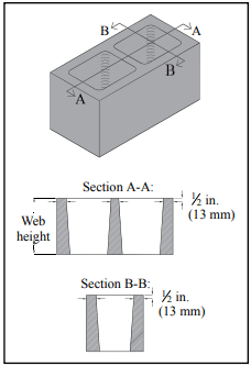
Unit dimensions are used: to verify that the overall length, width and height are within allowable tolerances; to calculate normalized web area and equivalent thickness; and to verify that face shell and cross web thicknesses meet the requirements of the appropriate unit specification (see Figure 1). Minimum face shell thickness is prescribed to address concerns such as ease of mortar placement, sufficient mortar coverage over joint reinforcement and resistance to lateral pressure from grouting. Minimum web thickness and area considerations include transfer of shear, flexural strength in the horizontal span, and resistance to tensile splitting of walls under compression.

Included in ASTM C140 since 2012 is testing to determine minimum normalized web area. Its purpose is to ensure that the unit has sufficient web material connecting the face shells. It replaces the equivalent web thickness criteria in previous versions of the standard. To determine the normalized web area, the minimum thickness and height of each web is measured and used to calculate the total web area of the unit. This total web area is divided by the nominal unit face area to determine normalized web area in in.²/ft² (mm²/m²).

Although not specified in ASTM C140 (ref. 1), the units set aside for absorption testing are typically used for measurement of unit dimensions, before the units are immersed in water. This way, the gross volume (determined from overall unit dimensions) and the net volume (determined from water displacement) for the units are both determined from the same set of test specimens.

Absorption

Absorption describes the amount of water a unit can hold when saturated. Absorption can be an indicator of the level of compaction of the concrete mix or of the volume of voids within a block. For a given mix design and manufacturing and curing process, variations in absorption can be an indication of deleterious materials in the mix, mixing quality, and/or compaction of the concrete mix, which also can indicate variations in compressive strength, tensile strength, durability, laboratory procedural problems, or other causes. Data collected during absorption testing is used to calculate absorption, density, net area, net volume and equivalent thickness.

Each unit is weighed a minimum of five times in this order: received weight; immersed weight; saturated surface dry weight; and oven-dry weight (at least twice). The saturated and immersed weights should always be determined following 24 to 28 hours of immersion and prior to oven drying the units.

Because the units are immersed in water and subsequently oven-dried during absorption testing, the units used for this determination should not be used for compression testing, the results of which are influenced by unit moisture content. Six units of identical size and configuration are therefore required for ASTM C140 testing—three for compression testing and three for absorption.

Compressive Strength

Compressive strength tests are used to ensure that concrete masonry units meet the minimum strength requirements of the applicable unit specification (see ref. 11). The unit compressive strength results may also be used to verify compliance with the specified compressive strength of masonry, f’m, when using the unit strength method (ref. 4, Article 1.4 B.2.b). Unit compression tests are easier and less expensive to perform than similar tests on masonry prisms, making the unit strength method the more popular.

Some of the critical areas of compression testing that are necessary to insure accurate testing include:

  • Appropriate capping stations with stiff, planar plates with smooth surfaces.
  • Compression machines with spherically seated heads and bearing plates of adequate planeness and thickness for the size of the specimen being tested. See TEK 18-01B (ref. 8) for details and an example.
  • Proper specimen alignment within the testing machine (center of mass aligned with center of thrust).

For compressive strength determination, three specimens are tested. Wherever possible, full-sized units are used. However, certain modifications are permitted or required as follows:

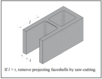
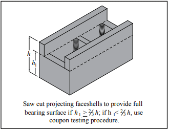
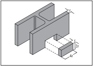
  • Unsupported projections with a length exceeding the projection thickness must be removed by saw-cutting (see Figure 2). For units with recessed webs, the face shell projecting above the web is removed by saw-cutting to provide a full bearing surface over the net cross-section of the unit, as shown in Figure 3.
  • When the size and/or strength of the unit exceeds the testing machine capacity, a specimen may be cut to conform to the testing machine capabilities. The resulting specimen, however, must contain an enclosed four-sided cell or cells without irregular face shells or webs.
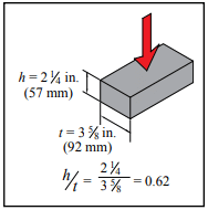
  • If saw-cutting does not produce a test specimen complying with the above provisions, coupons may be saw-cut from the face shells (see Figure 4).
  • For concrete roof paver units, cut three test specimens from three whole paver units to produce a strip of paver with the specimen height equal to its width. Where the paver has supporting ribs, cut the coupon perpendicular to the direction of the ribs, such that any bevelled or recessed surfaces are not included in the top or bottom edges of the specimen.
  • For concrete brick, specimens are required to have an aspect ratio (height divided by least lateral dimension) of 0.6 ± 0.1 (see Figure 5).

The prepared specimens are then capped in accordance with ASTM C1552 (ref. 9) to provide a uniform and level bearing surface. After the specimen center of mass is located, the specimen is positioned in the testing machine such that the specimen’s center of mass is aligned with the machine’s center of thrust. All hollow units are tested with their cores in a vertical direction, except for special units intended for use with their cores horizontal. These special units and units that are 100% solid are tested in the same direction as intended for service. Further information on compressive strength testing is available in references 8 and 12.

Calculations

Using the data gathered in the preceding test methods, the following characteristics are determined: absorption, density, average net area, gross area, net and gross area compressive strengths, normalized web area and equivalent thickness.

Density, or unit weight, is described in terms of dry weight per cubic foot. It is determined from the saturated weight, immersed weight and oven-dry weight. Using these weights, the volume of concrete in a unit is readily determined and its density is the oven-dry weight divided by its net volume. Among the properties affected by density of concrete in a block are wall weight, building weight, thermal conductivity, heat capacity and acoustical properties.

Cross-sectional area is the basis for expressing compressive strength of concrete masonry units. Unit specifications require that block comply with a minimum net area compressive strength. Net area is described in terms of the percentage of solid material in the cross section, and is measured by the ratio of net volume of the unit to gross volume of the unit. Because water displacement is used to determine net volume, the net cross-sectional area represents the average net area of the unit.

Equivalent thickness is used to determine the fire resistance rating. It represents the average thickness of a hollow unit if the volume is configured into a solid unit of the same face dimension. It is determined by dividing the net unit volume by the unit face area.

DRYING SHRINKAGE, ASTM C426

ASTM C426, Standard Test Method for Drying Shrinkage of Concrete Masonry Units (ref. 2) is intended to evaluate the potential shrinkage characteristics of concrete masonry units due to moisture loss only. Note that concrete masonry may also shrink due to factors such as carbonation and temperature changes, which are not addressed by this test method (although temperature is standardized and corrected so as not to influence the results). This test measures unit length change from a totally saturated condition to an “equilibrium” condition at 17% relative humidity. This represents the potential shrinkage because the masonry is unlikely to encounter these extreme conditions under normal circumstances. The test results are used to determine concrete masonry crack control provisions.

Typically, it is not necessary to run shrinkage tests on units made with the same mix design but having different unit configurations. As long as there are no changes in materials, mix design, production methods or curing, ASTM C426 tests are required to be performed only once every two years, per ASTM C90 (ref. 13).

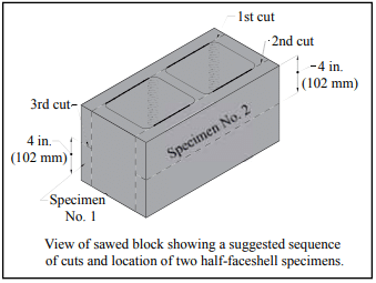
Test specimens are usually whole units with measurements taken on both faces. Alternatively, coupons may be cut from face shells, as illustrated in Figure 6. Gage plugs are mounted on the test specimens to facilitate length measurements.

This method requires the test specimens to be saturated for 48 hours, at which time the length is precisely measured and recorded. Specimens are then dried in an oven for 5 days. After drying, specimens are cooled and measured. Test specimens are then returned to the drying oven for periods of 48 hours until the length change is negligible.

PREFACED UNITS

For concrete masonry units with a smooth, resinous tile-like facing adhered to the unit, Standard Specification for Prefaced Concrete and Calcium Silicate Masonry Units, ASTM C744 (ref. 3) includes requirements and applicable test methods for the facing. The concrete masonry unit to which the facing is applied must comply with the applicable unit specification. Facing requirements include:

Resistance to crazing—Units are subjected to wetting and drying to demonstrate that the facing does not craze, crack or spall.
Resistance to chemicals—The facing must remain unchanged when subjected to the specified list of chemicals and exposure durations.
Adhesion—The facing must remain adhered to the unit when the unit is loaded to failure by an applied compression load.
Abrasion—The wear index of the facing must exceed 130 when the facing is subjected to a standard abrasion test (ASTM C501, ref. 5).
Surface burning—The flame spread and smoke density rating of the facing must not exceed 25 and 50, respectively, when tested in accordance with ASTM E84 (ref. 6).
Color tint & texture—The facing texture must remain unchanged and facing color difference must not exceed 5 Delta units (ref. 7) when subjected to an accelerated weathering test.
Soiling and cleansability—No more than a trace of stain may remain on the facing after cleaning when subjected to a specified list of marking substances.

REFERENCES

  1. Standard Test Methods for Sampling and Testing Concrete Masonry Units and Related Units, ASTM C140/C140M-14. ASTM International, 2014.
  2. Standard Test Method for Linear Drying Shrinkage of Concrete Masonry Units, ASTM C426-10. ASTM International, 2010.
  3. Standard Specification for Prefaced Concrete and Calcium Silicate Masonry Units, ASTM C744-14. ASTM International, 2014.
  4. Specification for Masonry Structures, TMS 602-13/ACI 530.1-13/ASCE 6-13. Reported by the Masonry Standards Joint Committee, 2013.
  5. Standard Test Method for Relative Resistance to Wear of Unglazed Ceramic Tile by the Taber Abraser, ASTM C501-84(2009). ASTM International, 2009.
  6. Standard Test Method for Surface Burning Characteristics of Building Materials, ASTM E84-14. ASTM International, 2014.
  7. Standard Practice for Calculation of Color Tolerances and Color Differences from Instrumentally Measured Color Coordinates, ASTM D2244-14. ASTM International, 2014.
  8. Evaluating the Compressive Strength of CM based on 2012IBC/2011 MSJC, TEK 18-01B. Concrete Masonry & Hardscapes Association, 2011.
  9. Standard Practice for Capping Concrete Masonry Units, Related Units and Masonry Prisms for Compression Testing, ASTM C1552-14. ASTM International, 2014.
  10. Standard Specification for Concrete Building Brick, ASTM C55-14. ASTM International, 2014.
  11. Concrete Masonry Unit Shapes, Sizes, Properties, and Specifications, CMU-TEC-001-23, Concrete Masonry & Hardscapes Association, 2023.
  12. Compressive Strength Testing Variables for CM Units, TEK 18-07, Concrete Masonry & Hardscapes Association, 2004..
  13. Standard Specification for Loadbearing Concrete Masonry Units, ASTM C90-14. ASTM International, 2014.


Steel Reinforcement for Concrete Masonry

INTRODUCTION

Reinforcement in concrete masonry walls increases strength and ductility, increases resistance to applied loads, and in the case of horizontal reinforcement, also provides increased resistance to shrinkage cracking. This TEK covers non-prestressed reinforcement for concrete masonry construction. Prestressing steel is discussed in Post-Tensioned Concrete Masonry Wall Construction, TEK 03-14 (ref. 1). Unless otherwise noted, the information is based on the 2003 International Building Code (IBC) (ref. 2). For masonry design and construction, the IBC references Building Code Requirements for Masonry Structures and Specification for Masonry Structures (MSJC Code and Specification) (refs. 4, 5). In some cases, the IBC has adopted provisions different from the MSJC provisions. These instances have been noted where applicable.

MATERIALS

Reinforcement used in masonry is principally reinforcing bars and cold-drawn wire products. Wall anchors and ties are usually formed of wire, metal sheets or strips. Table 1 lists applicable ASTM Standards governing steel reinforcement, as well as nominal yield strengths for each steel type.

Reinforcing Bars

Reinforcing bars are available in the United States in 11 standard bar sizes designated No. 3 through 11, No. 14 and No. 18 (M#10-36, M#43, M#57). The size of a reinforcing bar is designated by a number corresponding to its nominal diameter. For bars designated No. 3 through No. 8 (M#10-25), the number indicates the diameter in eighths of an inch (mm), as shown in Table 2.

To help address potential problems associated with reinforcement congestion and grout consolidation, the IBC limits the reinforcing bar diameter to the lesser of one-eighth the nominal member thickness, and one-fourth the least dimension of the cell, course or collar joint into which it is placed. For typical single wythe walls, this corresponds to a maximum bar size of No. 8, 9 and 11 for 8-, 10- and 12- in. walls, respectively (M#25, 29 and 36 for 203-, 254- and 305-mm walls). In addition, the following limits apply:

  • maximum bar size is No. 11 (M#36),
  • the area of vertical reinforcement may not exceed 6% of the grout space area (i.e., about 1.26 in.² , 1.81 in.² , or 2.40 in.² of vertical reinforcement for 8-, 10- and 12-in. concrete masonry, respectively (815, 1,170 or 1,550 mm² for 203-, 254- and 305-mm units, respectively), and
  • for masonry designed using strength design procedures, the maximum bar size is No. 9 (M#29) and the maximum area of reinforcement is 4% of the cell area (i.e., about 0.84 in.² , 1.21 in.² , or 1.61 in.² of vertical reinforcement for 8-, 10- and 12-in. concrete masonry, respectively (545, 781 or 1,039 mm² for 203-, 254- and 305-mm units, respectively).

The prescriptive limits on reinforcement sizes, above, are construction-related. Additional design limits to prevent over-reinforcing and brittle failures may also apply depending on the design method used and the design loads resisted. Manufacturers mark the bar size, producing mill identification and type of steel on reinforcing bars (see Figure 1). Note that the bar size indicates the size in SI units per ASTM standards.

The ASTM standards include minimum requirements for various physical properties including yield strength and stiffness. While not all reinforcing bars have a well-defined yield point, the modulus of elasticity, Es , is roughly the same for all reinforcing steels and for design purposes is taken as 29,000,000 psi (200 GPa).

When designing by the allowable stress design method, allowable tensile stress is limited to 20,000 psi (138 MPa) for Grade 40 or 50 reinforcing bars and 24,000 psi (165 MPa) for Grade 60 reinforcing bars. For reinforcing bars enclosed in ties, such as those in columns, the allowable compressive stress is limited to 40% of the specified yield strength, with a maximum of 24,000 psi (165 MPa). For strength design, the nominal yield strength of the reinforcement is used to size and distribute the steel.

Cold-Drawn Wire

Cold-drawn wire for joint reinforcement, ties or anchors varies from W1.1 to W4.9 (MW7 to MW32) with the most popular size being W1.7 (MW11). Table 3 shows standard wire sizes and properties. Because the IBC limits the size of joint reinforcement to one half the joint thickness, the practical limit for wire diameter is 3/16 in. (W2.8, 4.8 mm, MW18) for a in. (9.5 mm) bed joint. Wire for masonry is plain with the exception that side wires for joint reinforcement are deformed by means of knurling wheels.

Stress-strain characteristics of reinforcing wire have been determined by extensive testing programs. Not only is the yield strength of cold-drawn wire close to its ultimate strength, but the location of the yield point is not clearly indicated on the stress-strain curve. ASTM A 82 (ref. 15) defines yield as the stress determined at a strain of 0.005 in./in. (mm/mm).

CORROSION PROTECTION

Grout, mortar and masonry units usually provide adequate protection for embedded reinforcement provided that minimum cover and clearance requirements are met. Reinforcement with a moderate amount of rust, mill scale or a combination is allowed to be used without cleaning or brushing, provided the dimensions and weights (including heights of deformations) of a cleaned sample are not less than those required by the applicable ASTM standard. When additional corrosion protection is needed, reinforcement can be galvanized or epoxy coated.

Joint Reinforcement

Carbon steel can be protected from corrosion by coating the steel with zinc (galvanizing). The zinc protects in two ways: first, as a barrier separating the steel from oxygen and water, and second during the corrosion process, the zinc is sacrificed before the steel is attacked. Increasing the zinc coating thickness improves the level of corrosion protection.

Required levels of corrosion protection increase with the severity of exposure. When used in exterior walls or in interior walls exposed to a mean relative humidity over 75%, carbon steel joint reinforcement must be hot-dip galvanized or epoxy-coated, or stainless steel joint reinforcement must be used. When used in interior walls exposed to a mean relative humidity less than or equal to 75%, it can be mill galvanized, hot-dip galvanized, or be stainless steel. The corresponding minimum protection levels are:

  • Mill galvanized—ASTM A 641 (ref. 16) 0.1 oz/ft² (0.031 kg/m²)
  • Hot-dip galvanized—ASTM A 153 (ref. 17), Class B, 1.5 oz/ft² (458 g/m²)
  • Epoxy-coated—ASTM A 884 (ref. 18) Class A, Type 1 ≥ 7 mils (175 µm) (ref. 3). Note that both the 2003 IBC and 2002 MSJC code incorrectly identify Class B, Type 2 epoxy coated joint reinforcement, which is not applicable for masonry construction.

In addition, joint reinforcement must be placed so that longitudinal wires are embedded in mortar with a minimum cover of ½ in. (13 mm) when not exposed to weather or earth, and in. (16 mm) when exposed to weather or earth.

Reinforcing Bars

A minimum amount of masonry cover over reinforcing bars is required to protect against steel corrosion. This masonry cover is measured from the nearest exterior masonry surface to the outermost surface of the reinforcement, and includes the thickness of masonry face shells, mortar and grout. The following minimum cover requirements apply:

  • masonry exposed to weather or earth
    bars larger than No. 5 (M#16) …………………….2 in. (51 mm)
    No. 5 (M#16) bars or smaller……………………1½ in. (38 mm)
  • masonry not exposed to weather or earth … 1½ in. (38 mm)

PLACEMENT

Installation requirements for reinforcement and ties help ensure that elements are placed as assumed in the design, and that structural performance is not compromised due to mislocation. These requirements also help minimize corrosion by providing for a minimum amount of masonry and grout cover around reinforcing bars, and providing sufficient clearance for grout and mortar to surround reinforcement and accessories so that stresses can be properly transferred.

Reinforcing Bars

Tolerances for placing reinforcing bars are:

  • variation from d for walls and fl exural elements:
    d ≤ 8 in. (203 mm) ………………………. ±½ in. (13 mm)
    8 in. (203 mm) < d ≤ 24 in. (610 mm) ±1 in. (25 mm)
    d > 24 in. (610 mm) ……………………. ±1¼ in. (32 mm)
  • for vertical bars in walls ………..±2 in. (51 mm) from the specified location along the length of the wall.

In addition, a minimum clear distance between reinforcing bars and the adjacent (interior of cell) surface of a masonry unit of ¼ in. (6.4 mm) for fine grout or ½ in. (13 mm) for coarse grout must be maintained so that grout can flow around the bars.

DEVELOPMENT

Development length or anchorage is necessary to adequately transfer stresses between the reinforcement and the grout in which it is embedded. Reinforcing bars can be anchored by embedment length, hook or mechanical device. Reinforcing bars anchored by embedment length rely on interlock at the bar deformations and on sufficient masonry cover to prevent splitting from the reinforcing bar to the free surface. Detailed information and requirements for development, splice and standard hooks are contained in TEK 12-06A, Splices, Development and Standard Hooks for CM Based on the 2009 & 2012 IBC (ref. 19).

REFERENCES

  1. Post-Tensioned Concrete Masonry Wall Construction, TEK 03-14. Concrete Masonry & Hardscapes Association, 2002.
  2. International Building Code 2003. International Code Council, 2003.
  3. International Building Code 2006. International Code Council, 2006.
  4. Building Code Requirements for Masonry Structures, ACI 530-02/ASCE 5-02/TMS 402-02. Reported by the Masonry Standards Joint Committee, 2002.
  5. Specification for Masonry Structures, ACI 530.1-02/ASCE 6-02/TMS 602-02. Reported by the Masonry Standards Joint Committee, 2002.
  6. Standard Specification for Deformed and Plain Billet-Steel Bars for Concrete Reinforcement, ASTM A615/A615M-00. ASTM International, Inc., 2000.
  7. Standard Specification for Low-Alloy Steel Deformed and Plain Bars for Concrete Reinforcement, ASTM A706/A706M- 01. ASTM International, Inc., 2001.
  8. Standard Specification for Zinc-Coated (Galvanized) Steel Bars for Concrete Reinforcement, A767/A767M-00b. ASTM International, Inc., 2000.
  9. Standard Specification for Epoxy-Coated Steel Reinforcing Bars, A775/A775M-01. ASTM International, Inc., 2001.
  10. Standard Specification for Rail-Steel and Axle-Steel Deformed Bars for Concrete Reinforcement, A996/A996M-00. ASTM International, Inc., 2000.
  11. Standard Specification for Masonry Joint Reinforcement, ASTM A951-00. ASTM International, Inc., 2000.
  12. Standard Specification for Stainless and Heat-Resisting Steel Wire, ASTM A580-98. ASTM International, Inc., 1998.
  13. Standard Specification for Steel Wire, Deformed, for Concrete Reinforcement, A496/A496M-01. ASTM International, Inc., 2001.
  14. Manual of Standard Practice, MSP 1-01. Concrete Reinforcing Steel Institute, 2001.
  15. Standard Specification for Steel Wire, Plain, for Concrete Reinforcement, ASTM A82-01. ASTM International, Inc., 2001.
  16. Standard Specification for Zinc-Coated (Galvanized) Carbon Steel Wire, ASTM A641-98. ASTM International, Inc., 1998.
  17. Standard Specification for Zinc Coating (Hot-Dip) on Iron and Steel Hardware, ASTM A153-01a. ASTM International, Inc., 2001.
  18. Standard Specification for Epoxy-Coated Steel Wire and Welded Wire Fabric for Reinforcement, ASTM A884/A884M-99. ASTM International, Inc., 1999.
  19. Reinforcement Detailing Requirements for Concrete Masonry, TEK 12-06A. Concrete Masonry & Hardscapes Association, 2007.

TEK 12-04D, Revised 2006. Disclaimer: Although care has been taken to ensure the enclosed information is as accurate and complete as possible, CMHA does not assume responsibility for errors or omissions resulting from the use of this TEK.

Plaster and Stucco for Concrete Masonry

INTRODUCTION

Portland cement-based plaster has many useful applications: as a moisture resistant coating for concrete masonry walls; as an interior wall finish in residential and commercial structures; and as an exterior architectural treatment for buildings of all types.

The terms cement plaster and cement stucco are used interchangeably. They both describe a combination of cement and aggregate mixed with a suitable amount of water to form a plastic mixture that will adhere to a surface and preserve the texture imposed on it.

When freshly mixed, plaster is a pliable, easily workable material. It can be applied either by hand or machine in two or three coats, although two-coat applications are more typical when plaster is applied to newly constructed concrete masonry.

While plaster may be used as an interior or exterior finish for most building materials, some type of metal reinforcement or mechanical keying system is usually required to effectively attach the plaster to the substrate. Concrete masonry, however, provides an excellent base for plaster without the need for reinforcement. Since block is manufactured of the same cementitious material as that in the plaster, the two have a natural affinity.

MATERIALS

Of primary importance to the performance of the finished surface is the selection and use of proper materials. Each must be evaluated on its ability to provide serviceability, durability, and satisfactory appearance. Standard Specification for Application of Portland Cement-Based Plaster, ASTM C 926 (ref. 3) includes specifications for materials for use in plaster

Cement

Cement should comply to one of the following product specifications:

  • Blended hydraulic cement —ASTM C 595 (ref. 4)
    Types IP, IP(M), IS, IS(M), and their air-entrained
    counterparts IP-A, IP(M)-A, IS-A, IS(M)-A
  • Masonry cement—ASTM C 91 (ref. 5) Types M, S, N
  • Portland cement—ASTM C 150 (ref. 6)
    Types I, II, III, and their air-entrained counterparts IA, IIA,
    IIIA
  • Plastic cement—UBC 25-1 (ref. 1)
  • White portland cement—ASTM C 150 (ref. 6) Types I, IA,
    III, IIIA

Aggregates

Aggregates used in plaster should conform to the chemical and physical requirements of ASTM C 897, Standard Specification for Aggregate For Job-Mixed Portland Cement Plasters (ref. 2), except as noted below. Recommendations for gradation of the sand to be used in the base coat are listed in Table 1.

Aggregates used for finish coats need not comply with the gradation requirements of ASTM C 897. Various sizes and shapes can be evaluated with test panels to obtain special textures or finishes. As a starting point, all aggregates for finish-coat plaster should be below a No. 16 sieve and uniformly graded. Uniform gradation produces plaster that is easier to apply. If necessary, larger aggregate may be added to obtain the desired appearance.

MIXTURES

Properly proportioned mixtures can be recognized by their workability, ease of application, adhesiveness to the base, and resistance to sagging.

The combinations of cementitious materials and aggregates shown in Table 2 have proven to provide satisfactory performance. These proportions are recommended for first and second coat applications.

Considerations in selecting the plaster mix include suction of the masonry, its surface irregularities, climate extremes, extent of surface exposure, and method of application. For economy and simplicity, it is better to select the same plaster type for both scratch (first) and brown coat (second coat in a three coat application) applications, adjusting the proportions for the brown coat to allow for a larger aggregate to cement ratio.

The finish coat can be varied in appearance by changing the size and shape of the aggregate, by adding color, by changing the consistency of the finish mix, and by the application method. For the finish coat, a factory prepared mixture may be used or the finish coat may be proportioned and mixed at the jobsite. Job-mixed finish coat plaster will provide a truer color and more pleasing appearance if white portland cement is used in conjunction with a fine-graded, light colored sand. Recommendations for job mixed finish coat proportions are listed in Table 3.

The success of plastering depends on proper batching and mixing of the individual and combined materials. Water is placed in the mixer first, after which half of the sand is added. Next the cement and any admixtures are added. Finally, the balance of the sand is added and mixing is continued until the batch is uniform and of the proper consistency, which usually takes 3 or 4 minutes.

Although batching by shovelfuls remains the most commonly used method in the field, shovelful batching should be checked daily by volume measures to establish both the required number of shovelfuls of each ingredient and the volume of mortar in the mixer when a batch is properly proportioned. Water additions should also be batched using containers of known volume. Proper mixing should result in a uniform blend of all materials.

PLASTER APPLICATION

Open textured concrete masonry units, laid with flush (nontooled) joints, should be specified on walls intended to be plastered. The open texture promotes a good mechanical bond between the plaster and the masonry. New concrete masonry walls should be properly aligned and free from any surface contamination, such as mortar droppings or sand. It is important that the wall be properly cured and carrying almost all of its design dead load before the plaster is applied. Existing masonry walls should be inspected for alignment, and any coatings or surface treatments other than portland cement paint be should removed by sandblasting prior to plastering.

Plaster may be applied by hand or machine in two or three coats in accordance with the thicknesses given in Table 4. Two-coat application is most often used when plaster is applied directly to concrete masonry, and for horizontal (overhead) plaster application.

The scratch coat can be applied either from the bottom to the top of the work area, or from top to bottom. The plaster must be applied with sufficient force to fully adhere it to the masonry. Excessive troweling or movement of the scratch coat must be avoided, because too much action will break the bond between the plaster and masonry. The applied plaster must be brought to the required thickness and the surface made plumb. The thickness is established by the use of screeds and grounds. A rod or straightedge is used to even the surface when the area between the screeds and grounds is filled with plaster. The rod can bear on the screeds or contact the grounds and be moved over the surface, cutting off high spots and showing up the hollow spaces, which must be filled and rodded again.

Scratch-coat plasters are scored or scratched to promote mechanical bond when the brown coat is applied. The scratch coat should be scored in a horizontal direction; shallow scratching is adequate.

Brown-coat plasters are applied, rodded, and floated to even the surface, provide a uniform suction throughout the basecoat plaster, and provide a desirable surface for the finish coat.

The brown coat is applied in sufficient thickness to bring the surface to the proper plane. A few minutes after the plaster has been applied, the surface is rodded to the desired plane. The plaster thickness is properly gaged with plaster screeds or wood slats of proper thickness as the guides. After rodding, the surface is floated to give it the correct surface texture.

Floating of the brown coat is the most important part of plastering. Floating must be done only after the plaster has lost sufficient moisture so that the surface sheen has disappeared but before the plaster has become so rigid that it cannot be moved under the float. This interval is critical, since the degree of consolidation that occurs during floating influences the shrinkage-cracking characteristics of the plaster.

The full thickness of the base coats should be applied as rapidly as the two coats can be put in place. The second coat should be applied as soon as the first coat is sufficiently rigid to resist the pressures of second-coat application without cracking. Under certain conditions this may mean applying both first and second coats in a single day. The short delay, or even no delay, between the first and second coats promotes more intimate contact between them and more complete curing of the base coat. No stoppage of plaster should occur within a panel. The finish coat is applied to a predamped, but still absorptive, base coat to a thickness of about 1/8 in. (3.2 mm). The finish coat is applied from the top down and the whole wall surface must be covered without joinings (laps or interruptions). Table 4 summarizes the recommended nominal plaster coat thicknesses for both two and three coat work.

Differential suction between the masonry units and mortar joints may cause joint patterns to be visible in two coat applications if the first coat is too thin. This may also occur if the walls are plastered while the units contain excessive moisture.

CONTROL JOINTS

Cracks can develop in plaster from a number of causes: drying shrinkage stresses; building movement; foundation settlement; intersecting walls, ceilings, and pilasters; weakened sections in a wall from a reduction in service area or cross section because of fenestration; severe thermal changes; and construction joints.

To prevent such cracking, install control joints in the plaster coat directly over and aligned with any control joints in the base. Normally, cracking will not occur in plaster applied to uncracked masonry bases if the plaster bonds tightly to the base structure. If excessive cracking does occur, the application (particularly floating) procedure may not have provided adequate bond of plaster to concrete masonry. Altering application procedures or mechanically anchoring the plaster to the concrete masonry surface with mesh may be required.

CURING

To obtain the best results from the cementitious materials in cement plaster, moisture must be kept in the plaster for the first few days after application. The base coat should be moist cured until the finish coat is applied. Generally, fogging the surface with water at the start and again at the end of the work day will suffice. If it is hot, dry, and windy, the plaster surface should be moistened and covered with a single sheet of polyethylene plastic, weighted or taped down to prevent water loss through evaporation.

Immediately before finish-coat application, the base coat should be moistened. This moisture absorbed by the base coat and the ambient relative humidity provides total curing of the finish coat plaster (particularly colored finish coats) so that it is not necessary to further moist-cure the finish coat.

MAINTENANCE OF PLASTER

Minimal care will keep plaster attractive for many years.
Washing will keep the surface clean and the color bright.
Washing plaster wall surfaces consists of three steps:

  1. Prewet the wall, saturating it. Start at the bottom and work to the top.
  2. Use a garden hose to direct a high-pressure stream of water against the wall to loosen the dirt. Start at the top and wash the dirt down the wall to the bottom.
  3. Flush remaining dirt off the wall with a follow-up stream.

Prewetting overcomes absorption and prevents dirty wash water from being absorbed and dulling the finish. A jet nozzle on a garden hose will usually clean effectively. Do not hold the nozzle too close to the surface because the high pressure stream of water may erode the surface.

Chipped corners and small spalls can be patched with premixed mortar. The patch area should be wetted before applying plaster. Prepare premixed mortar by adding water and mixing to a doughy consistency, then trowel into the patch area, and finish to match the texture of the surrounding surface.

A fresh, new look can be given to any exterior plaster wall by applying a surface treatment of paint, portland cement paint, or other coating. Portland cement paints are mixed with clean water to a brushable consistency and laid on heavily enough to fill and seal small cracks and holes. The surface should be dampened immediately before application.

REFERENCES

  1. Plastic Cement, Uniform Building Code Standard 25-1, International Conference of Building Officials (ICBO), 1994.
  2. Standard Specification for Aggregate for Job-Mixed Portland Cement-Based Plasters, ASTM C 897-00. American Society for Testing and Materials, 2000.
  3. Standard Specification for Application of Portland Cement Based Plaster, ASTM C 926-98a. American Society for Testing and Materials, 1998.
  4. Standard Specification for Blended Hydraulic Cements, ASTM C 595-02. American Society for Testing and Materials, 2002.
  5. Standard Specification for Masonry Cement, ASTM C 91-
  6. American Society for Testing and Materials, 2001.
  7. Standard Specification for Portland Cement, ASTM C 150-
  8. American Society for Testing and Materials, 2000.

Self-Consolidating Grout for Concrete Masonry

INTRODUCTION

Self-consolidating grout (SCG) is a specially-formulated grout for use with reinforced masonry. It is designed to fill the long, narrow and sometimes highly congested cores of reinforced walls without the need for consolidation and reconsolidation by mechanical vibration or by puddling.

Self-consolidating grout has been used in various parts of the United States, under the grout demonstration panel provisions of Specification for Masonry Structures (refs. 1, 2), which is included by reference in the International Building Code (refs. 3, 4). The 2008 edition of Specification for Masonry Structures (ref. 5), however, includes explicit provisions for SCG.

Unlike conventional grout and conventional concrete, self consolidating grout (SCG) is a special application of self consolidating concrete (SCC) that uses aggregates complying with ASTM C 404, Standard Specification for Aggregates for Masonry Grout (ref. 6), as specified in ASTM C 476, Standard Specification for Grout for Masonry (ref. 7).

Similar to conventional grout, there are two types of selfconsolidating grout, coarse and fine, with the latter containing only fine aggregate. Coarse self-consolidating grout has been the most common, although fine SCG is predominant in several specific regions of the U.S.

MATERIALS FOR SELF-CONSOLIDATING GROUT

Self-consolidating grout attains a high flow not from adding more water, but from a careful mix design to create a flowable yet highly cohesive grout that will not segregate and can pass freely through congested reinforcement and narrow openings without “blocking or bridging.” SCG must maintain its fluidity without segregation and maintain consistent properties throughout the grout lift. It is composed of aggregates, cementitious materials, water and special admixtures which provide the fluidity and stability to meet performance requirements.

Aggregate Size and Proportion

To obtain the desired filling and placing ability, aggregates used in SCG should meet the requirements of ASTM C 404, as specified in ASTM C 476. The requirements for coarse aggregate, for use in coarse SCG, are essentially the same as the requirements for No. 8 and No. 89 coarse aggregate in ASTM C 33, Standard Specification for Concrete Aggregates (ref. 8): they should be either a Size No. 8 or Size No. 89 gravel, stone or air-cooled iron blast furnace slag with 100% passing the ½ in. (13 mm) sieve and at least 85 to 90% passing the 3/8 in. (9.5 mm) sieve. Fine aggregate, for use in either coarse or fine SCG, is typically Size No. 1, which is a concrete sand as defined in ASTM C 33, but could also be Size No. 2, which is a sand for masonry mortar as defined in ASTM C 144, Specification for Aggregate for Masonry Mortar (ref. 9).

ASTM C 476 contains a proportion specification as well as a performance specification for masonry grout. The proportion specification specifies that coarse grout should have fine aggregate in the amount of 2 1/4 to 3 times the sum of the volume of the cementitious materials and coarse aggregate in the amount of 1 to 2 times the sum of the volume of the cementitious materials. These ASTM C 476 requirements are equivalent to s/a (sand/total aggregate) ratios of approximately 0.50 to 0.60 on an absolute volume basis. By comparison, most self-consolidating concrete mix designs have similar s/a ratios in the 0.50 to 0.60 range.

Cementitious Materials and Minus 100 (0.150 mm) Sieve Content and Composition

Grout is required to have a minimum compressive strength of 2,000 psi (14 MPa) after 28 days of curing (ref. 7). Building Code Requirements for Masonry Structures (ref. 10) sets an upper limit on the specified compressive strength of grout at 5,000 psi (34.5 MPa) at 28 days when using strength design of concrete masonry, although experience indicates that many conventional grouts develop strengths greater than this specification limit. Note that actual strengths are somewhat higher than the specified strength to assure compliance.

In the historical context of masonry materials, the term cementitious materials has commonly referred to the cement content (as well as lime in the case of masonry mortars) used in the manufacturing of masonry units, mortar or grout. In the production of SCG, however, the fraction of very fine aggregate particles present in the mix can have a significant influence on the plastic (and by association, the hardened) properties of SCG, and therefore needs to be considered in the batching of SCG. As such, the ‘powder’ content of an SCG mix, which includes both conventional cementitious materials as well as the very fine aggregate dust smaller than the 100 (0.150 mm) sieve, is monitored to ensure a stable SCG.

Adequate paste content is critical for making stable SCG mixes because the paste forms the matrix in which the particles are suspended. This paste is composed of cementitious materials (including the powder), water and entrained air, if any. The entire powder content of some mixes may contain auxiliary materials including pozzolanic and hydraulic materials, as well as ground limestone and inert fillers. These additions can improve and maintain cohesion and segregation resistance of the mix while lowering the overall cost and helping to control the ultimate strength of the mix.

Although not widely used in the U.S., ground limestone and inert fillers can be very effective in SCG mixes as a means of keeping compressive strengths to the lower range. They should be considered if they are regionally available. Fly ash can also be an effective addition because its use can help enhance the filling ability and slump flow of the mix while providing increased cohesion and reduced sensitivity to changes in water content.

Research has shown that slump flow values are increased when the fly ash replacement rates are between 20 and 40% of portland cement (ref. 11). If the goal is to control compressive strengths, Class F fly ash can be effective because it typically does not contribute as much to strength gain as Type C fly ash. GGBFS (Ground Granulated Blast Furnace Slag) has successfully been used in SCG mixes to replace some of the cement, but its high ultimate strength gain usually means that the compressive strengths of these mixes are usually similar (or sometimes higher) than straight cement mix designs. Research (ref. 12) has demonstrated that coarse SCG mixes could be made with total cementitious materials contents of 750 lb/yd3 (445 kg/m3), and possibly with 700 lb/yd3 (415 kg/m3). By comparison, a typical conventional coarse grout made to the proportion specifications of ASTM C 476 contains about 550 to 700 lb/yd3 (325 to 415 kg/m3) of cementitious materials.

Some limited testing in the CMHA research (ref. 12) demonstrated that fine SCG could be made with total cementitious materials contents in the range of 800 to 850 lb/yd3 (475 to 505 kg/m3). By comparison, a typical conventional fine grout made to the proportion specifications of ASTM C 476 will contain about 700 to 1,000 lb/yd3 (415 to 590 kg/m3) of cementitious materials.

Water Content

The term ‘natural slump’ describes the slump of the grout mix before the polycarboxylate is added. A common procedure for making self consolidating concrete is to set the initial water target to the amount needed to bring the mix to a ‘natural slump’ of 2 to 4 in. (51 to 102 mm). The polycarboxylate is then added to make the mix fluid enough to obtain the desired slump flow. This would also be an acceptable initial water target for making SCG, although CMHA research (ref. 12) indicated that some of the most successful batches of coarse and fine SCG made with the local materials used in the research had initial water targets that yielded a ‘natural slump’ of 6 to 9 in. (152 to 229 mm) before the polycarboxylate was added.

Admixtures

Admixtures are integral to the production of SCG. The primary admixture used to impart fluidity and stability to the SCG mix is a class of high-range water-reducing admixtures known as polycarboxylates (PC). These long-chain polymers are synthesized to help keep the cement grains dispersed while adding some cohesiveness and stability to the SCG mix.

Another class of admixtures often used to make SCG in conjunction with the PC is the Viscosity-Modifying Admixtures (VMA). VMAs help adjust viscosity and can improve the cohesiveness and stability of the mix while allowing it to flow without segregation. Not all PC and VMA products have the same properties. Some PCs impart substantial amounts of stability and cohesiveness to the mix and are recommended to be used without VMA, while others benefit from the addition of VMA.

In the past (before polycarboxylates), there have been indications that in some situations superplasticizers in grout for masonry structures have not performed well because they exhibited a short pot life, meaning the mix quickly lost fluidity and rapid stiffing would follow. Absorption of mix water into the surrounding masonry also negatively impacted the flow. In high-lift grouting (placing grout into grout columns as high as 24 ft (7.3 m)), enough water could be lost to cause the grout to stiffen and bridge before reaching the bottom of the grout column. With the advent of newer high-range water reducers such as polycarboxylates, however, this problem is no longer evident (ref. 13).

Note that proportioning of SCG is not permitted in the field (ref. 5). However, final adjustment of the mix, in accordance with the SCG manufacturer’s recommendations, utilizing water or the same admixture used in the mix is permitted.

SCG PLACEMENT

Self-consolidating grout is pumped or placed into spaces to be grouted using the same procedures as for conventional grout. Research has shown that with SCG there is no need to first remove mortar fins and protrusions exceeding 1/2 in. (13 mm), as is required for conventionally grouted masonry (refs. 3, 4), since SCG is fluid enough to flow around these small obstructions (ref. 13). However, it is important to note that Specification for Masonry Structures currently requires the removal of mortar fins and protrusions exceeding 1/2 in. (13 mm) for both conventional grout and SCG (ref. 5). Note that because SCG is so fluid, it will flow through gaps wider than about 3/8 in.

(10 mm). To contain the grout, therefore, it is recommended to mortar the masonry unit cross webs of cells containing grout in partially grouted construction.

In bond beams, SCG will be adequately contained using conventional grout-stop materials, such as plastic mesh. When filling intermediate bond beams using high-lift grouting, place the grout-stop material in the bed joints both above and below the bond beam to prevent the SCG from rising above the bond beam location.

Once the SCG is placed, consolidation and reconsolidation is not necessary with either coarse or fine SCG.

Documented successful lifts of 12 ft 8 in. (3.9 m) have been achieved by filling the grout columns of 8-in. (203-mm) concrete masonry walls in a single lift in less than a minute using a concrete pump (ref. 13). Other undocumented placements have placed SCG in a single 24-ft (7.3-m) lift. Twenty-four feet (7.3 mm) is the maximum pour height currently permitted by Building Code Requirements for Masonry Structures and Specification for Masonry Structures (refs. 10, 5). Note also that for SCG, grout lift height can equal the grout pour height.

Blowouts have not been shown to be a problem for conventional masonry units in this research nor in field experience. However, specialty units with reduced or removed webs, such as “H-block” or large pilaster or column units, may require reduced lift heights.

No special curing procedures are required when using SCG. When appropriate, standard hot and cold weather construction provisions should be followed, as for other masonry projects. See All-Weather Concrete Masonry Construction, TEK 03-01C (ref. 14), for more detailed information.

SCG QUALITY ASSURANCE AND QUALITY CONTROL

Specification for Masonry Structures (ref. 5) requires SCG to:

  • meet the material requirements of ASTM C 476,
  • attain the specified compressive strength or 2,000 psi (13.79 MPa), whichever is greater, at 28 days when tested in accordance with ASTM C 1019 (ref. 15),
  • have a slump flow of 24 to 30 in. (610 to 762 mm) as determined by ASTM C 1611 (ref. 16), and
  • have a Visual Stability Index (VSI) less than or equal to 1 as determined in accordance with ASTM C 1611, Appendix X.1.

The ASTM C 476 material requirements are described in Grout for Concrete Masonry, TEK 09-04A (ref. 17). Other quality assurance and quality control provisions related to SCG are described below.

Some methods commonly used for self-consolidating concrete to evaluate passing ability, like the L-Box or J-Ring, are not normally used with SCG because experience indicates that the 3/8 in. (9.5 mm) maximum aggregate size used in SCG has adequate passing ability in masonry grouting applications.

Compressive Strength Testing of SCG Mixes

The current edition of ASTM C 1019, Standard Test Method for Sampling and Testing Grout (ref. 15), addresses the testing of SCG. The procedure for testing SCG is very similar to that for conventional grout, except that SCG is placed in the mold in one lift instead of two and SCG does not need to be rodded.

Slump Flow

The slump flow test method defined in ASTM C 1611/C 1611M, Standard Test Method for Slump Flow of Self-Consolidating Concrete (ref. 16) is used to monitor the consistency of fresh, unhardened SCG and its unconfined flow potential. It is particularly useful to assess the batch-to-batch consistency of SCG supplied over time.

Because of the fluid nature of SCG, traditional measures of consistency, such as the ASTM C 143 (ref. 18) slump test, are not applicable to SCG. The slump flow test is an adaptation of the ASTM C 143 slump cone test. In the slump flow test, SCG is loaded into an inverted slump cone in a single lift without consolidation. The cone is removed and the diameter of the grout slump flow is measured (see Figure 1).

Visual Stability Index (VSI)

VSI, also defined in ASTM C 1611, is performed after the slump flow test to provide a qualitative assessment of the SCG’s stability. The SCG patty resulting from the slump flow test is examined for aggregate segregation, bleeding and evidence of a mortar halo (a cement paste or mortar ring that has clearly separated from the coarse aggregate, around the outside circumference of the SCG patty). The SCG mix is then assigned a VSI, from 0 (highly stable) to 3 (highly unstable).

Although not required by Specification for Masonry Structures, T20 (T50) records the time it takes, during the slump flow test, for the outer edge of the SCG patty to reach a diameter of 20 in. (508 mm) from the time the mold is first raised. It is an optional test for self consolidating concrete, and is similarly applicable to SCG to provide a relative measure of the unconfined flow rate and an indication of the relative viscosity of the SCG. While the actual target value for T20 (T50) can vary for different SCG mixes, it has value in verifying the consistency between SCG batches delivered to the job site.

Self-Healing Ability ‘S’ Test

The ‘S’ test can also be used to help determine the stability of an SCG mix. While this is not a standardized test method, it is adapted from a simple test that is done by some practitioners in the field. There is a common version and a modified version, which gives an indication of the relative segregation resistance of the SCG when subjected to local vibration.

The common self-healing (non-disturbed) test is performed after the slump flow, T20 (T50) and VSI have been recorded. A 10- to 12-in. (254- to 305-mm) ‘S’ is drawn in the SCG patty with a finger, making sure to scrape off the SCG all the way down to the board. The patty is observed to see if the ‘S’ will self-heal. In cases where the self healing is excellent, the SCG flows back together and there is little or no evidence of the ‘S’ remaining. In cases where the self-healing is poor, the SCG does not flow back together and the ‘S’ remains very visible with severe aggregate, paste or water segregation.

Due to observations during the CMHA research (ref. 12), a self healing (after agitate) test was created. After completing the common self-healing test, the SCG patty is vibrated and a second test, designated self-healing (after agitate), is performed. To vibrate the mix, the side of the slump flow baseplate is lightly kicked or tapped six times with a foot (three on one side followed by three on an orthogonal [right-angle] side). The ‘S’ test is then repeated and the mix is rated again.

Suitability of Segregation Tests

In the CMHA research (ref. 12); several mixes were used to determine the suitability of self-consolidating concrete segregation tests on the SCG mixes. Testing was performed to evaluate both the Column Technique for Static Segregation (ASTM C 1610) (ref. 19) and the European Sieve Segregation Test (ref. 20). It was found that these tests were not able to distinguish unstable SCG mixes from stable mixes. It is not clear if this was a function of the particular raw materials used or a general characteristic of coarse SCG mixes. The selfhealing (after agitation) test described above was found to be a much better indicator of stable and unstable mixes for SCG.

REFERENCES

  1. Specification for Masonry Structures, ACI 530.1-02/ASCE
    6-02/TMS 602-02. Reported by the Masonry Standards
    Joint Committee, 2002.
  2. Specification for Masonry Structures, ACI 530.1-05/ASCE
    6-05/TMS 602-05. Reported by the Masonry Standards
    Joint Committee, 2005.
  3. International Building Code 2003. International Code
    Council, 2003.
  4. International Building Code 2006. International Code
    Council, 2006.
  5. Specification for Masonry Structures, ACI 530.1-08/ASCE
    6-08/TMS 602-08. Reported by the Masonry Standards
    Joint Committee, 2008.
  6. Standard Specification for Aggregates for Masonry Grout,
    ASTM C 404-07. ASTM International, Inc., 2007.
  7. Standard Specification for Grout for Masonry, ASTM C
    476-07. ASTM International, Inc., 2007.
  8. Standard Specification for Concrete Aggregates, ASTM C
    33-03. ASTM International, Inc., 2003.
  9. Standard Specification for Aggregate for Masonry Mortar,
    ASTM C 144-04. ASTM International, Inc., 2004.
  10. Building Code Requirements for Masonry Structures, ACI
    530-08/ASCE 5-08/TMS 402-08. Reported by the Masonry
    Standards Joint Committee, 2008.
  11. Studies of Self-Compacting High Performance Concrete
    with High Volume Mineral Additives. Fang, W.;Jianxiong,
    C.; Changhui, Y., Proceedings of the First International
    RILEM Symposium on Self-Compacting Concrete, 1999,
    p. 569-578.
  12. Self-Consolidating Grout Investigation: Making and
    Testing Prototype SCG Mix Designs – Report of Phase
    II Research, MR31. Concrete Masonry & Hardscapes
    Association, 2006.
  13. Self-Consolidating Grout Investigation: Compressive
    Strength, Shear Bond, Consolidation and Flow – Report
    of Phase I Research, MR29. Concrete Masonry &
    Hardscapes Association, 2006.
  14. All-Weather Concrete Masonry Construction, TEK 03-01C,
    Concrete Masonry & Hardscapes Association, 2002.
  15. Standard Test Method for Sampling and Testing Grout,
    ASTM C 1019-07. ASTM International, Inc., 2007.
  16. Standard Test Method for Slump Flow of SelfConsolidating Concrete, ASTM C 1611/C 1611M-05.
    ASTM International, Inc., 2005.
  17. Grout for Concrete Masonry, TEK 09-04A, Concrete
    Masonry & Hardscapes Association, 2005.
  18. Standard Test Method for Slump of Hydraulic-Cement
    Concrete, ASTM C 143-05a. ASTM International, Inc.,
    2005.
  19. Standard Test Method for Static Segregation of SelfConsolidating Concrete Using Column Technique, ASTM
    C 1610/C 1610M-06. ASTM International, Inc., 2006.
  20. The European Guidelines for Self-Compacting Concrete:
    Specification, Production and Use. Self Compacting
    Concrete European Project Group, 2005.

Mortars for Concrete Masonry

INTRODUCTION

While mortar represents only a small proportion of the total wall area in concrete masonry construction (approximately 7 percent), its influence on the performance of a wall is significant. Mortar serves many important functions: it bonds units together into an integral structural assembly, seals joints against penetration by air and moisture, accommodates small movements within a wall, accommodates slight differences between unit sizes, and bonds to joint reinforcement, ties and anchors so that all elements perform as an assembly.

MORTAR MATERIALS

The American Society for Testing and Materials (ASTM) maintains national standards for mortars and materials commonly used in mortars, as follows:

Portland cement (ASTM C 150, ref. 4d) is a hydraulic cement (sets and hardens by chemical reaction with water) and is one of the main constituents of mortar. Types I (normal), II (moderate sulfate resistance), and III (high early strength) are permitted according to ASTM C 270 (ref. 4f). Air-entrained portland cements (IA, IIA, and IIIA) may be used as alternatives to each of these types.

Masonry cement (ASTM C 91, ref. 4b) is a hydraulic cement consisting of a mixture of portland cement or blended hydraulic cement and plasticizing materials (such as limestone, hydrated or hydraulic lime) together with other materials introduced to influence such properties as setting time, workability, water retention, and durability. Masonry cements are classified as Type M, Type S, or Type N according to ASTM C 270. In addition, Type N masonry cement can be combined with portland cement or blended hydraulic cement to produce Type S or M mortars.

Mortar cement (ASTM C 1329, ref. 4j) is a hydraulic cement similar to masonry cement, with the added requirement of a minimum bond strength requirement.

Blended hydraulic cements (ASTM C 595, ref. 4g) consist of standard portland cement or air-entrained portland cement (denoted by -A) combined through blending with such materials as blast furnace slag (S), or pozzolan (P & PM) which is usually fly ash. Types IS, IS-A, IP, IP-A, I(PM), or I(PM)-A blended cements may be used as alternatives to portland cement to produce ASTM C 270 compliant mortars. Types S or SA (slag cement) may also be used in mortars meeting the property specification requirements of ASTM C 270 (Table 2 of this TEK).

Quicklime (ASTM C 5, ref. 4a) is calcined (burneddecarbonated) limestone, the major constituents of which are calcium oxide (CaO) and magnesium oxide (MgO). Quicklime must be slaked (combined chemically with water) prior to use. The resultant lime putty must be stored and allowed to hydrate for at least 24 hours before use. Consequently, quicklime is rarely used in mortar.

Hydrated lime (ASTM C 207, ref. 4e) is a dry powder obtained by treating quicklime with enough water to satisfy its chemical affinity for water. ASTM C 207 designates Type N (normal), Type S (special), and air-entraining Type NA and Type SA hydrated limes. Slaking of hydrated lime is not required, thus hydrated lime is immediately usable and much more convenient than quicklime. ASTM C 207 limits the amount of unhydrated oxides in Type S or Type SA hydrated limes, assuring the soundness of mortar made using these limes. Types N or NA lime are not typically used in mortar; however, they are permitted if shown by test or performance record to not be detrimental to the soundness of the mortar. Air-entrained limes are only permitted in mortars containing nonair-entrained cement.

Aggregates (ASTM C 144, ref. 4c) for mortar consist of either natural or manufactured sand. Manufactured sand is the product obtained by crushing stone, gravel, or air cooled blast furnace slag. It is characterized by sharp, angular shaped particles. Gradation limits are established in ASTM C 144 for both natural and manufactured sands. Aggregates which fail these gradation limits may be used, as long as the resulting mortar complies with the property specification requirements of ASTM C 270, as shown in Table 2.

Water for masonry mortar (ASTM C 270, ref. 4f) must be clean and free of deleterious amounts of acids, alkalis, or organic materials. Potability of water is not in itself a consideration, but the water obtained from drinking supply sources is considered suitable for use.

Admixtures (also sometimes called modifiers or additives) for masonry mortars (ASTM C 1384, ref. 4k) are available for various purposes. Admixtures are functionally classified as bond enhancers, workability enhancers, set accelerators, set retarders, and water repellents. Since chlo-rides accelerate the corrosion of steel reinforcement and accessories ASTM C 1384 stipulates that admixtures add not more than 65 ppm (0.0065%) water-soluble chloride or 90 ppm (0.0090%) acidsoluble chloride by weight of portland cement. Similarly, the Specifications for Masonry Structures (ref. 3) limits admixtures to no more than 0.2% chloride ions. The document also limits pigments for coloring to no more than 1 to 10% by weight of cement depending upon the pigment type.

Effect of Materials on Mortar

With the diversity of materials available, masonry mortars can be formulated to produce the desired properties for most specific job requirements. Each of the individual ingredients (cement, lime, sand, water, and any modifiers present) contributes to the performance of the mortar. Portland cement provides strength and durability. Lime imparts workability, water retention, as well as some limited cementitious and autogenous healing properties. Sand acts as a filler and provides body to the mortar while helping to reduce shrinkage and control cracking. Water acts as a mixing agent, a lubricant, and is also needed for hydration of the portland cement.

The various material options alter the characteristics of the mortar in a predictable manner. Changes in cement type promote slight changes in setting characteristics, workability, color, and strength development. Use of air-entrained cement or lime generally results in decreased water demand, improved workability, increased freeze thaw resistance, and decreased bond strength. Masonry cements, used singly or in combination with portland cement, provide mortars with excellent workability and freeze-thaw durability; however, bond strengths may be reduced. Consequently, design allowable flexural tension values vary based on mortar type and cementitious materials or lime used for unreinforced masonry (ref. 1).

Changes in sand type and gradation affect mortar properties. Natural sand gives improved workability at a lower water demand because of the spherical particle shape, while manufactured sands require additional water due to their angular shape. In general, well graded aggregates reduce segregation in a plastic mortar, which in turn inhibits bleeding and improves workability. Sands deficient in fines generally produce harsh mortars, while sands with excessive fines typically result in mortars with lower compressive strengths.

TYPES OF MORTAR

Building codes generally specify mortar types as referenced in ASTM C 270, Standard Specification for Mortar for Unit Masonry (ref. 4f). Four mortar types, M, S, N and O are included in this standard. However, Types M, S, and N are typically required by building codes. Building codes also may restrict the use of some mortars for particular applications. For example, empirical design of foundation walls requires Type M or S mortar and glass unit masonry requires Type N or S mortar (ref. 1). In seismic design categories , D, E, and F portland cement/ lime or mortar cement mortar Types S or M are required (ref. 1).

PROPORTIONING MORTAR

All mortar types are governed by either of the two specifications contained in ASTM C 270: the proportion specification or the property specification. Only one of the specifications should be called for in the project documents, not both. The proportion specification (Table 1) prescribes the parts by volume of each ingredient required to provide a specific mortar type. A combination of portland cement and lime may be used as the cementing agent in each type of mortar. Also, masonry cements (ref. 4b) or mortar cements (ref. 4j) are available that meet the requirements of M, S, and N mortars with or without further addition of cement.

As an alternative, approved materials may be mixed in controlled percentages as long as the resultant mortar meets the physical requirements designated in ASTM C 270, as shown in Table 2. The aggregate ratio noted in Table 2 must be followed. Conformance to the property specification of ASTM C 270 is established by testing laboratory prepared mortar during a pre-construction evaluation of the mortar proposed for the project. The laboratory then establishes proportions for mortar, based on successful tests. These proportions are then followed when preparing field mortar.

MASONRY MORTAR PROPERTIES

Many properties of mortar are not precisely definable in quantitative terminology because of a lack of definitive standards by which to measure them. For example, mortars can be rated on the basis of obtaining visually satisfactory mortar joints.

Depending on the particular circumstances for a given project, the criteria for mortar selection are based on design considerations, mortar properties in the plastic state or mortar properties in a hardened state. Consideration of each is necessary to achieve a desired result.

Properties of Plastic Mortar

Workability is the property of mortar characterized by the smooth plastic consistency which makes it easy to spread. This is the property of most importance to the mason. A workable mortar spreads easily under the trowel; adheres to vertical surfaces during unit handling, placement, and bedding; maintains alignment as other units are positioned; and provides a watertight, closed joint when tooled.

Once mix proportions have been established, the addition of water should be consistent with that required to improve mortar placement without sacrificing the ability to support the masonry unit. Adequate water content promotes intimate contact between the unit and mortar, which is essential for satisfactory bond. While water content has the greatest influence on the workability of a mortar, cementitious materials, aggregate gradation, and air-entrainment also contribute to a lesser degree.

Water retention of mortar is a measure of the mortar’s ability to retain its plasticity when subjected to the atmosphere or the absorptive forces of a concrete masonry unit. Mortars with low water retention stiffen more quickly, making it difficult for the mason to bed and adjust the masonry unit during placement. Mortars with desired water retention characteristics allow the mason to lay a mortar bed two or three units ahead before placing subsequent units. Water retentivity is dependent on properties of the cementitious materials, sand gradation, and mortar proportions.

The time lapse between spreading a mortar bed and placing block should be kept to a minimum, because the workability will be reduced as water is absorbed into the block. If too much time elapses before a block is placed on a fresh mortar bed, units are less easily positioned and the bond will be reduced.

Evaporation of the mixing water from mortar may require retempering (mixing in additional water). This generally is not harmful as long as it is done prior to hydration of the mortar. To avoid the stiffening effects of hydration, mortar must be placed in final position within 21/2 hours after the original mixing (ref. 3) unless special set retarding admixtures are used.

Properties of Hardened Mortar

Properties of hardened mortar that affect the performance of the finished concrete masonry include bond, compressive strength, and durability. These properties are difficult to measure other than in laboratory or field specimens prepared under controlled conditions. However, ASTM C 1324, Standard Test Method for Examination and Analysis of Hardened Masonry Mortar, (ref. 4i) provides procedures for petrographic examination and chemical analysis for components of masonry mortar in the hardened state. A 0.35 oz. (10 g) sample is usually sufficient for both the petrographic and chemical analysis. When obtaining the sample, however, it is important to ensure that the sample is representative of the mortar in question, i.e. original mortar as opposed to pointing mortar or other mortars used on the project.

Bond is a term used to describe both the extent of contact between mortar and unit and the strength of adhesion. Bond is a function of several factors including mortar properties, unit surface characteristics, workmanship, and curing. Other factors being equal, bond strength will increase as the compressive strength of the mortar increases, although not in direct proportion. Bond may also be effectively increased through the use of properly designed mortars having water contents which provide good workability.

Compressive strength is perhaps the most commonly measured property of mortar but is perhaps the most misunderstood. Whenever compressive strength results are intended to be used to determine conformance of a mortar to the property specifications of ASTM C 270, compressive strength tests must be conducted in accordance with the laboratory procedures required by ASTM C 270. However, field mortar compressive testing is to be conducted in accordance with ASTM C 780, Standard Test Method for Preconstruction and Construction Evaluation of Mortars for Plain and Reinforced Unit Masonry, (ref. 4h) and is only to verify the consistency of materials and procedures, not to determine mortar strength (ref. 3). ASTM C 780 contains no requirement for minimum compressive strength of field mortar. The the mortar strength in the wall will be much higher than the field test because of the reduced water cement ratio due absorption of mix water into the masonry units and a greatly reduced shape factor in the mortar joint versus the mortar test cube. ASTM C 780 recognizes this and states that the strength should not be construed as being representative of the actual strength of the mortar.

Durability of mortar also is an important consideration for parapets or other walls with an extreme exposure to the weather. Oversanding or overtempering can decrease durability. High strength mortars and air entrained mortars provide increased durability. For more detailed discussion on field testing of mortar see TEK 18-05B, Masonry Mortar Testing (ref. 2).

REFERENCES

  1. Building Code Requirements for Masonry Structures, ACI 530-02/ASCE 5-02/TMS 402-02. Reported by the Masonry Standards Joint Committee, 2002.
  2. Masonry Mortar Testing, TEK 18-05B, Concrete Masonry & Hardscapes Association, 2014.
  3. Specifications for Masonry Structures, ACI 530.1-02/ASCE 6-02/TMS 602-02. Reported by the Masonry Standards Joint Committee, 2002.
  4. 2004 Annual Book of ASTM Standards, American Society for Testing and Materials:
    4a. C 5-03, Standard Specification for Quicklime for Structural Purposes.
    4b. C 91-03a, Standard Specification for Masonry Cement.
    4c. C 144-03, Standard Specification for Aggregate for Masonry Mortar.
    4d. C 150-04, Standard Specification for Portland Cement.
    4e. C 207-04, Standard Specification for Hydrated Lime for Masonry Purposes.
    4f. C 270-03b, Standard Specification for Mortar for Unit Masonry.
    4g. C 595-03, Standard Specification for Blended Hydraulic Cements.
    4h. C 780-02, Standard Test Method for Preconstruction and Construction Evaluation of Mortars for Plain and Reinforced Unit Masonry.
    4i. C 1324-03, Standard Test Method for Examination and Analysis of Hardened Masonry Mortar.
    4j. C 1329-04, Standard Specification for Mortar Cement.
    4k. C 1384-03, Standard Specification for Admixtures for Masonry Mortars.

Determining the Recycled Content of Concrete Masonry Products

INTRODUCTION

Sustainable development has been defined as development that meets the needs of the present without compromising the ability of future generations to meet their own needs (ref.1). This is often expressed as a holistic approach to building design, with the goal of optimizing environmental, economic and social impacts, from site selection through building operation and maintenance. A sustainable building optimizes resource management and operational performance, while minimizing risks to human health and the environment. As such, providing a sustainable building project encompasses far-reaching design decisions, and recognizes the interrelationships between virtually all elements and phases of the project.

A range of products and programs has been developed to help designers achieve a more sustainable built environment. Whether in the form of design guidelines for particular building types, or rating systems that step the design team through a series of design considerations, all aim to provide practical guidance for achieving the almost overwhelming goal of sustainability.

Referenced and in some cases mandated by some branches of the Federal government, as well as many state and local governments, the United States Green Building Council’s (USGBC) Leadership in Energy and Environmental Design (LEED®) has become perhaps the most widely used of these programs in recent years. LEED is a voluntary rating system designed to provide guidance as well as national third-party certification for defining what constitutes a “green” building.

Concrete masonry building and hardscape products can make a significant contribution to meeting LEED certification. This contribution is augmented by the recycled content potential of the companion products necessary for a concrete masonry wall, such as grout, mortar and reinforcement products.

Concrete masonry building and hardscape materials can contribute to earning credits in several LEED categories, including Sustainable Sites, Energy and Atmosphere, Materials and Resources and Innovation in Design. More detail on LEED strategies incorporating concrete masonry and hardscape materials is available in TEK 06 09C, Concrete Masonry and Hardscape Products in LEED 2009 and PAV-TEC-016-16, Achieving LEED Credits with Segmental Concrete Pavement (refs. 2, 3).

LEED includes specific rating systems for various applications. The information in this TEK is applicable to LEED for new construction, school, retail, and core and shell development (refs. 4-7).

For these LEED programs, Materials and Resources Credit 4: Recycled Content allows up to two LEED certification points for using materials with recycled content. The inert nature of concrete masonry lends itself well to incorporating recycled materials as cement replacements, as aggregates and as other constituents in the concrete mix. This TEK provides guidance on determining the recycled content of concrete masonry products for the purpose of earning LEED credit under the new construction, school, retail, and core and shell development LEED programs.

The LEED for Homes (ref. 8) recycled content credit differs from these other programs. Concrete masonry walls are eligible for recycled content credit under the LEED for Homes Materials and Resources Credit 2: Environmentally Preferable Products, provided the masonry contains at least 25% recycled content (post-consumer plus one-half pre-consumer, as described in the following sections). Note, however, that the National Association of Home Builders with the International Code Council has developed their own green building standard that has similar requirements (ref. 9). See www.nahbgreen.org for more information.

USE OF RECYCLED MATERIALS IN CONCRETE MASONRY AND HARDSCAPE UNITS

When concrete masonry products incorporate recycled materials, due consideration must be given to ensure that the use of these materials does not adversely affect the quality or safety of the units or construction. Note that some recycled materials may only be regionally available. Designers should work closely with concrete masonry manufacturers to substantiate recycled content.

Unit Specifications

Whether produced using recycled or virgin materials, concrete masonry products are required to meet the applicable ASTM unit specification (see Table 1). These standards contain minimum requirements that assure properties necessary for quality performance. For example, many concrete masonry units are required to conform to ASTM C90, Standard Specification for Loadbearing Concrete Masonry Units (ref. 11). ASTM C90 requirements include material requirements for aggregates, cementitious materials, and other constituent materials, physical requirements, finish and appearance requirements, and permissible variations in dimensions.

Aggregates, including recycled aggregates, for concrete masonry units are required to meet ASTM C33, Standard Specification for Concrete Aggregates, or C331, Standard Specification for Lightweight Aggregates for Concrete Masonry Units (refs. 19, 20), except that grading requirements do not have to be met. Aggregate characteristics governed include limits on deleterious substances and aggregate soundness.

Cements are required to meet ASTM C150 and supplemental cementitious materials such as fly ash must meet ASTM C618 (refs. 27, 28). In addition to cementitious materials and aggregates, the ASTM unit specifications also allow for the inclusion of “Other Constituents,” such as pigments, integral water repellents and finely ground silica. For a material to qualify for inclusion in a concrete masonry product under this provision, the material:

  • must have been previously established as suitable for use in the product, and
  • must either conform to applicable ASTM standards or be shown, via test or experience, not to be detrimental to the durability of the units or other masonry materials.

Fire Resistance Ratings

For construction requiring a fire resistance rating, the use of recycled aggregates may impact the method used to determine the hourly rating, because concrete masonry fire resistance ratings vary with the aggregate type(s) used to manufacture the units. Concrete masonry fire ratings can be determined by: model building code prescriptive tables (ref. 21), a standard calculation method as provided in Section 721 of the International Building Code (IBC) (ref. 21) and the ACI/TMS 216 (ref. 22); testing in accordance with ASTM E 119, Standard Test Methods for Fire Tests of Building Construction and Materials (ref. 23); commercial listing services; and deemed-to comply assemblies included in some building codes. These tools also include ways to increase a wall system’s fire resistance rating through careful placement of additional materials.

Currently, the standard calculation procedure applies to the following aggregate types: expanded slag, pumice, expanded clay, expanded shale, expanded slate, limestone, cinders, aircooled slag, calcareous gravel, and siliceous gravel. When units are made with a combination of these aggregates, the fire rating is determined by interpolation (see ref. 23 for more detail). When aggregate types other than those listed above are used, the fire resistance rating is determined using a method other than the standard calculation procedure.

TEK 07-01D, Fire Resistance Rating of Concrete Masonry Assemblies (ref. 24) contains a detailed discussion of concrete masonry fire ratings. Additional considerations for recycled aggregates which are not listed in the standard calculation procedure are their stability, safety and load-carrying ability when subjected to fire.

LEED MATERIALS & RESOURCES CREDIT 4: RECYCLED CONTENT

By increasing the demand for products that incorporate recycled materials, the Recycled Content credits are intended to reduce the environmental and societal impacts associated with extracting and processing virgin materials.

LEED awards 1 point to projects that demonstrate that the total amount of a project’s recycled content exceeds 10% based on both weight and the total building product costs. An additional point is awarded if the recycled content reaches 20%. Also, if the recycled content reaches 30%, a third point can be earned as an Innovation & Design credit.

LEED refers to the International Organization for Standardization (ISO) for the definition of what constitutes recycled content, and for the basis of determining the percentage – i.e., weight (ref. 25). Recycled materials are those materials diverted from the solid waste stream, either during the manufacturing process (pre-consumer) or after their intended use (post-consumer). The recycled content for LEED credit is determined as the sum of all post-consumer recycled content plus one-half of the pre-consumer recycled content.

To claim this credit, the LEED NC Reference Guide suggests establishing a project goal for recycled content materials, and dentifying product suppliers who can achieve this goal. The following sections describe how concrete masonry and hardscape products can contribute to recycled content goals.

Pre-Consumer Recycled Content

Pre-consumer (post-industrial) content as defined by the LEED v2.2 reference manual is “material diverted from the waste stream during the manufacturing process. Excluded is reutilization of materials such as rework, regrind or scrap generated in a process and capable of being reclaimed within the same process that generated it (Source ISO 14021). Examples in the pre-consumer category include planer shavings, plytrim, sawdust, chips, bagasse, sunflower seed hulls, walnut shells, culls, trimmed materials, print overruns, over-issue publications, and obsolete inventories.” (refs. 4, 25) It is important for the producer to work with the material suppliers to determine which materials can be considered recycled and which cannot. It is important for the producer to have documentation from the material supplier stating that a material is considered recycled for the purposes of contributing to LEED certification.

Post-Consumer Recycled Content

Post-consumer recycled content is consumer waste that can no longer be used for its intended purpose. The official LEED definition of a post-consumer material is “material generated by households or by commercial, industrial and institutional facilities in their role as end users of the product which can no longer be used for its intended purpose. This includes returns of materials from the distribution chain (ref. 26). Examples of materials in this category include construction and demolition debris, materials collected through curbside and drop off recycling programs, broken pallets (if from a pallet refurbishing company, not a pallet-making company), discarded products (e.g. furniture, cabinetry and decking) and urban maintenance waste (leaves, grass clippings, tree trimmings, etc.) (refs. 4, 25).

As with pre-consumer materials, a producer should work with the material supplier to document that the materials being used are specifically documented as post-consumer recycled material for the purposes of contributing to LEED certification.

DETERMINING RECYCLED CONTENT

The LEED recycled content credit(s) is based on the recycled content percentages, based on the total value of all permanently installed materials on the project. Note that mechanical, electrical and plumbing components are excluded from this total, as are specialty items such as elevators. In determining the percentages of recycled content, the contribution from concrete masonry and hardscape products is added to the contribution from other building components.

The following sections describe the procedure for determining the recycled content of a particular product, then combining all such data to determine the overall recycled content percentage for the project. The percentages are based on both weight and cost, as described below.

For a Product

The producer is responsible for reporting the percentages of reconsumer and post-consumer recycled content for each product sold. If the producer supplies other products in addition to block such as reinforcement, mortar, etc., the producer should also document the recycled percentages in each of these products and report them to the contractor who purchased them.

The percentages are based on weight, as follows:

As an aid to the producer, CMHA has developed a simple spreadsheet to calculate these percentages (see Figure 1). Figure 1 illustrates the process of determining the weights of all constituent materials; determining the total weight; then determining the percent by weight of each recycled material. The total pre-consumer and post consumer percentages are simply the sum of the individual material percentages in each category.

Note that Figure 1 includes an alternate calculation, applicable to concrete products only. This alternate calculation is described below.

For a Product: Alternate Calculation per LEED for New Construction and Major Renovations

LEED for New Construction and Major Renovations, Version 2.2 and the LEED Reference Guide for Green Building Design and Construction, 2009 Edition (ref. 5, 26) provide an alternate method to calculate and report the recycled content for concrete products that use supplementary cementitious materials (SCMs), such as fly ash or ground blast furnace slag cement. This alternate method allows the recycled content calculation to be based on only the cementitious materials, rather than on all materials in the concrete mix. This alternate method helps offset the fact that the recycled content calculation is based on weight, and SCMs are typically very low in weight. For concrete mixes with SCMs as the only recycled content, this alternate method will result in a higher recycled content value than the conventional approach. For concrete mixes that incorporate both SCMs and other recycled materials, the manufacturer may want to evaluate the percent recycled content using both methods to determine which method yields the best result.

The basic calculation is the same as that described in the previous section, except:

  • when determining the percent post-consumer and percent pre consumer recycled content, divide by the total weight of the cementitious materials only, and
  • when determining the recycled content value, multiply the percent recycled content by the total value of the cementitious materials only.

Use of the alternative calculation method requires that the value of the cementitious materials be used in place of the total value of the product when the LEED project team determines the value of the recycled content. The producer would likely benefit from describing this value as a percentage of the value of the whole product and not as a monetary figure. When requested, the producer should report this value to the direct customer and not to a third party.

For the Project as a Whole

Based on information from the product suppliers, the design team determines the recycled content value for the project as a whole as follows:

  1. For each product, the percent recycled content is determined as the percent post-consumer (reported by the supplier) plus one-half of the percent pre-consumer. For the example in Figure 1, the percent recycled content for the concrete masonry units is 17.9% + 1/2(37.1%) = 36.5%
  2. For each product, the recycled content value is determined as the percent recycled content multiplied by the total product cost for the project. For the hypothetical project referenced in Figure 1, if the total cost of the concrete masonry units is $90,000, the recycled content value of the concrete masonry units is 0.365($90,000) = $32,805. It is important to note that the cost used in this calculation is the amount paid to the producer or the contractor for the product. It is not the cost of the individual materials that constitute the concrete masonry or hardscape product. The product cost should be supplied by the contractor. It is the contractor’s responsibility to separate their labor charges from the material charges.
  3. For the project as a whole, the recycled content percentage is determined as the sum of the recycled content values of each product, divided by the total cost of all of these products. If this total recycled content percentage is 10% or higher, the project earns one LEED point; if it is 20% or higher the project earns two LEED points. Projects with recycled content percentages of 30% or more may be eligible for an additional Innovation in Design point.

CONCRETE MASONRY UNITS RETURNED FROM A JOB SITE

Unused concrete masonry units returned to the manufacturer from a job site are considered under Materials and Resources Credit 2: Construction Waste Management. Under Credit 2, the building project with unused materials can earn LEED point(s) for returning those materials, and hence diverting them from a landfill. If subsequently used on another project, the recycled content of the units as manufactured is reported to the contractor or design team, as for unused concrete masonry products.

REFERENCES

  1. Standard Terminology for Sustainability Relative to the Performance of Buildings, ASTM E2114-06a. ASTM International, Inc., 2006.
  2. Concrete Masonry and Hardscape Products in LEED 2009, TEK 06-09C, Concrete Masonry & Hardscapes Association, 2009.
  3. Achieving LEED Credits with Segmental Concrete Pavement, PAV TEC-016-16, Concrete Masonry & Hardscapes Association, 2016.
  4. LEED for New Construction and Major Renovations, Version 2.2, 3rd ed. U. S. Green Building Council, 2005.
  5. LEED for Schools for New Construction and Major Renovations, Version 2007. U. S. Green Building Council, 2007.
  6. LEED for Retail: New Construction and Major Renovations, Version 3. U. S. Green Building Council, 2008.
  7. LEED Green Building Rating System for Core and Shell Development, Version 2.0. U. S. Green Building Council, 2006.
  8. LEED for Homes Rating System. U. S. Green Building Council, 2008.
  9. NAHB Model Green Home Building Guidelines. National Association of Home Builders, 2006.
  10. Standard Specification for Concrete Brick, ASTM C55-06e1. ASTM International, 2006.
  11. Standard Specification for Loadbearing Concrete Masonry Units, ASTM C90-06b. ASTM International, Inc., 2006.
  12. Standard Specification for Nonloadbearing Concrete Masonry Units, ASTM C129-06. ASTM International, 2006.
  13. Standard Specification for Prefaced Concrete and Calcium Silicate Masonry Units, ASTM C744-05. ASTM International, 2005.
  14. Standard Specification for Concrete Facing Brick, ASTM C1634-06. ASTM International, 2006.
  15. Standard Specification for Solid Concrete Interlocking Paving Units, ASTM C936-08. ASTM International, 2008.
  16. Standard Specification for Concrete Grid Paving Units, ASTM C1319-01(2006). ASTM International, 2006.
  17. Standard Specification for Dry-Cast Segmental Retaining Wall Units, ASTM C1372-04e2. ASTM International, 2002.
  18. Standard Specification for Concrete Masonry Units for Construction of Catch Basins and Manholes, ASTM C139-05. ASTM International, 2005.
  19. Standard Specification for Concrete Aggregates, ASTM C33-07. ASTM International, Inc., 2007.
  20. Standard Specification for Lightweight Aggregates for Concrete Masonry Units, C331-05. ASTM International, Inc., 2005.
  21. International Building Code, International Code Council. 2006 and 2009 editions.
  22. Code Requirements for Determining Fire Resistance of Concrete and Masonry Construction Assemblies, ACI 216.1-07/TMS 216-07. American Concrete Institute and The Masonry Society, 2007.
  23. Standard Test Methods for Fire Tests of Building Construction and Materials, ASTM E119-08a. ASTM International, Inc., 2008.
  24. Fire Resistance Rating of Concrete Masonry Assemblies, TEK 07-01D, Concrete Masonry & Hardscapes Association, 2018.
  25. Environmental Labels and Declarations – Self-Declared Environmental Claims (Type II Environmental Labeling), ISO 14021-1999. International Organization for Standardization, 1999.
  26. LEED Reference Guide for Green Building Design and Construction, 2009 Edition. U.S. Green Building Council, 2009.
  27. Standard Specification for Portland Cement, ASTM C150-07. ASTM International, 2007.
  28. Standard Specification for Coal Fly Ash and Raw or Calcined Natural Pozzolan for Use in Concrete. C618-08a. ASTM International, 2008.

Concrete Masonry Construction

INTRODUCTION

Concrete masonry is a popular building material because of its strength, durability, economy, and its resistance to fire, noise, and insects. To function as designed however, concrete masonry buildings must be constructed properly.

This TEK provides a brief overview of the variety of materials and construction methods currently applicable to concrete masonry. In addition, a typical construction sequence is described in detail.

MATERIALS

The constituent masonry materials: concrete block, mortar, grout, and steel, each contribute to the performance of a masonry structure. Concrete masonry units provide strength, durability, fire resistance, energy efficiency, and sound attenuation to a wall system. In addition, concrete masonry units are manufactured in a wide variety of sizes, shapes, colors, and architectural finishes achieve any number of appearances and functions. The Concrete Masonry Shapes and Sizes Manual (ref. 4) illustrates a broad sampling of available units.

While mortar constitutes approximately 7% of a typical masonry wall area, its influence on the performance of a wall is significant. Mortar bonds the individual masonry units together, allowing them to act as a composite structural assembly. In addition, mortar seals joints against moisture and air leakage and bonds to joint reinforcement, anchors, and ties to help ensure all elements perform as a unit.

Grout is used to fill masonry cores or wall cavities to improve the structural performance and/or fire resistance of masonry. Grout is most commonly used in reinforced construction, to structurally bond the steel reinforcing bars to the masonry, allowing the two elements to act as one unit in resisting loads.

Reinforcement incorporated into concrete masonry structures increases strength and ductility, providing increased resistance to applied loads and, in the case of horizontal reinforcement, to shrinkage cracking.

Specifications governing material requirements are listed in Table 1.

CONSTRUCTION METHODS

Mortared Construction

Most concrete masonry construction is mortared construction, i.e., units are bonded together with mortar. Varying the bond or joint pattern of a concrete masonry wall can create a wide variety of interesting and attractive appearances. In addition, the strength of the masonry can be influenced by the bond pattern. The most traditional bond pattern for concrete masonry is running bond, where vertical head joints are offset by half the unit length.

Excluding running bond construction, the most popular bond pattern with concrete masonry units is stack bond. Although stack bond typically refers to masonry constructed so that the head joints are vertically aligned, it is defined as masonry laid such that the head joints in successive courses are horizontally offset less than one quarter the unit length (ref. 2). Concrete Masonry Bond Patterns (ref. 3), shows a variety of bond patterns and describes their characteristics.

Dry-Stacked Construction

The alternative to mortared construction is dry-stacked (also called surface bonded) construction, where units are placed without any mortar, then both surfaces of the wall are coated with surface bonding material. Shims or ground units are used to maintain elevations. This construction method results in faster construction, and is less dependent on the skill of the laborer than mortared construction. In addition, the surface bonding coating provides excellent rain penetration resistance. Surface Bonded Concrete Masonry Construction (ref. 9), contains further information on this method of construction.

CONSTRUCTION SEQUENCE

Mixing Mortar

To achieve consistent mortar from batch to batch, the same quantities of materials should be added to the mixer, and they should be added in the same order. Mortar mixing times, placement methods, and tooling must also be consistent to achieve uniform mortar for the entire job.

In concrete masonry construction, site-mixing of mortar should ideally be performed in a mechanical mixer to ensure proper uniformity throughout the batch. Mortar materials should be placed in the mixer in a similar manner from batch to batch to maintain consistent mortar properties. Typically, about half the mixing water is added first into a mixer. Approximately half the sand is then added, followed by any lime. The cement and the remainder of the sand are then added. As the mortar is mixed and begins to stiffen, the rest of the water is added. Specification for Masonry Structures (ref. 7) requires that these materials be mixed for 3 to 5 minutes. If the mortar is not mixed long enough, the mortar mixture may not attain the uniformity necessary for the desired performance. A longer mixing time can increase workability, water retention, and board life.

The mortar should stick to the trowel when it is picked up, and slide off the trowel easily as it is spread. Mortar should also hold enough water so that the mortar on the board will not lose workability too quickly, and to allow the mason to spread mortar bed joints ahead of the masonry construction. The mortar must also be stiff enough to initially support the weight of the concrete masonry units.

To help keep mortar moist, the mortarboard should be moistened when a fresh batch is loaded. When mortar on the board does start to dry out due to evaporation, it should be retempered. To retemper, the mortar is mixed with a small amount of additional water to improve the workability. After a significant amount of the cement has hydrated, retempering will no longer be effective. For this reason, mortar can be retempered for only 1 ½ to 2 ½ hours after initial mixing, depending on the site conditions. For example, dry, hot, and windy conditions will shorten the board life, and damp, cool, calm conditions will increase the board life of the mortar. Mortar should be discarded if it shows signs of hardening or if 2 ½ hours have passed since the original mixing.

Placing Mortar

Head and bed joints are typically in. (10 mm) thick, except at foundations. Mortar should extend fully across bedding surfaces of hollow units for the thickness of the face shell, so that joints will be completely filled. Solid units are required to be fully bedded in mortar.

Although it is important to provide sufficient mortar to properly bed concrete masonry units, excessive mortar should not extend into drainage cavities or into cores to be grouted. For grouted masonry, mortar protrusions extending more than ½ in. (13 mm) into cells or cavities to be grouted should be removed (ref. 7).

The Importance of Laying to the Line

Experienced masons state that they can lay about five times as many masonry units when working to a mason line than when using just their straightedge. The mason line gives the mason a guide to lay the block straight, plumb, at the right height, and level. The line is attached so that it gives a guide in aligning the top of the course.

If a long course is to be laid, a trig may be placed at one or more points along the line to keep the line from sagging. Before work begins, the mason should check to see that the line is level, tight, and will not pull out.

Each mason working to the same line needs to be careful not to lay a unit so it touches the line. This will throw the line off slightly and cause the rest of the course to be laid out of alignment. The line should be checked from time to time to be certain it has remained in position.

PLACING UNITS

The Foundation

Before building the block wall, the foundation must be level, and clean so that mortar will properly adhere. It must also be reasonably level. The foundation should be free of ice, dirt, oil, mud, and other substances that would reduce bond.

Laying Out the Wall

Taking measurements from the foundation or floor plan and transferring those measurements to the foundation, footing, or floor slab is the first step in laying out the wall.

Once two points of a measurement are established, corner to corner, a chalk line is marked on the surface of the foundation to establish the line to which the face of the block will be laid. Since a chalk line can be washed away by rain, a grease crayon, line paint, nail or screwdriver can mark the surface for key points along the chalk line, and a chalk line re-snapped along these key points. After the entire surface is marked for locations of walls, openings, and control joints, a final check of all measurements should be made.

The Dry Run—Stringing Out The First Course

Starting with the corners, the mason lays the first course without any mortar so a visual check can be made between the dimensions on the floor or foundation plan and how the first course actually fits the plan. During this dry layout, concrete blocks will be strung along the entire width and length of the foundation, floor slab, and even across openings. This will show the mason how bond will be maintained above the opening. It is helpful to have in. (10 mm) wide pieces of wood to place between block as they are laid dry, to simulate the mortar joints.

At this dry run the mason can check how the block will space for openings which are above the first course—windows, etc., by taking away block from the first course and checking the spacing for the block at the higher level. These checks will show whether or not units will need to be cut. Window and door openings should be double checked with the window shop drawings prior to construction.

When this is done, the mason marks the exact location and angle of the corners. It is essential that the corner be built as shown on the foundation or floor plan, to maintain modular dimensions.

Laying the Corner Units

Building the corners is the most precise job facing the mason as corners will guide the construction of the rest of the wall. A corner pole can make this job easier. A corner pole is any type of post which can be braced into a true vertical position and which will hold a taut mason’s line without bending. Corner poles for concrete block walls should be marked every 4 or 8 in. (102 to 203 mm), depending on the course height, and the marks on both poles must be aligned such that the mason’s line is level between them.

Once the corner poles are properly aligned, the first course of masonry is laid in mortar. Typically, a mortar joint between ¼ and ¾ in. (6.4 to 19 mm) is needed to make up for irregularities of the footing surface. The initial bed joint should be a full bed joint on the foundation, footing, or slab. In some areas, it is common practice to wet set the initial course of masonry directly in the still damp concrete foundation.

Where reinforcing bars are projecting from the foundation footing or slab, the first course is not laid in a full mortar bed. In this case, the mason leaves a space around the reinforcing bars so that the block will be seated in mortar but the mortar will not cover the area adjacent to the dowels. This permits the grout to bond directly to the foundation in these locations.

After spreading the mortar on the marked foundation, the first block of the corner is carefully positioned. It is essential that this first course be plumb and level.

Once the corner block is in place, the lead blocks are set— three or four blocks leading out from each side of the corner. The head joints are buttered in advance and each block is lightly shoved against the block in place. This shove will help make a tighter fit of the head joint, but should not be so strong as to move the block already in place. Care should be taken to spread mortar for the full height of the head joint so voids and gaps do not occur.

If the mason is not working with a corner pole, the first course leads are checked for level, plumb, and alignment with a level.

Corners and leads are usually built to scaffold height, with each course being stepped back one half block from the course below. The second course will be laid in either a full mortar bed or with face shell bedding, as specified.

Laying the Wall

Each course between the corners can now be laid easily by stretching a line between. It should be noted that a block has thicker webs and face shells on top than it has on the bottom. The thicker part of the webs should be laid facing up. This provides a hand hold for the mason and more surface area for mortar to be spread. The first course of block is thereafter laid from corner to corner, allowing for openings, with a closure block to complete the course. It is important that the mortar for the closure block be spread so all edges of the opening between blocks and all edges of the closure block are buttered before the closure block is carefully set in place. Also, the location of the closure block should be varied from course to course so as not to build a weak spot into the wall.

The units are leveled and plumbed while the mortar is still soft and pliable, to prevent a loss of mortar bond if the units need to be adjusted.

As each block is put in place, the mortar which is squeezed out should be cut off with the edge of the trowel and care should be taken that the mortar doesn’t fall off the trowel onto the wall or smear the block as it is being taken off. Should some mortar get on the wall, it is best to let it dry before taking it off.

All squeezed out mortar which is cut from the mortar joints can either be thrown back onto the mortar board or used to butter the head joints of block in place. Mortar which has fallen onto the ground or scaffold should never be reused.

At this point, the mason should:

  • Use a straightedge to assure the wall is level, plumb and aligned.
  • Be sure all mortar joints are cut flush with the wall, awaiting tooling, if necessary.
  • Check the bond pattern to ensure it is correct and that the spacing of the head joints is right. For running bond, this is done by placing the straightedge diagonally across the wall. If the spacing of head joints is correct, all the edges of the block will be touched by the straightedge.
  • Check to see that there are no pinholes or gaps in the mortar joints. If there are, and if the mortar has not yet taken its first set, these mortar joint defects should be repaired with fresh mortar. If the mortar has set, the only way they can be repaired is to dig out the mortar joint where it needs repairing, and tuckpoint fresh mortar in its place.
Tooling Joints

When the mortar is thumbprint hard, the head joints are tooled, then the horizontal joints are finished with a sled runner and any burrs which develop are flicked off with the blade of the trowel. When finishing joints, it is important to press firmly, without digging into the joints. This compresses the surface of the joint, increasing water resistance, and also promotes bond between the mortar and the block. Unless otherwise required, joints should be tooled with a rounded jointer, producing a concave joint. Once the joints are tooled, the wall is ready for cleaning.

Cleanup

Masonry surfaces should be cleaned of imperfections that may detract from the final appearance of the masonry structure including stains, efflorescence, mortar droppings, grout droppings, and general debris.

Cleaning is most effective when performed during the wall construction. Procedures such as skillfully cutting off excess mortar and brushing the wall clean before scaffolding is raised, help reduce the amount of cleaning required.

When mortar does fall on the block surface, it can often be removed more effectively by letting it dry and then knocking it off the surface. If there is some staining on the face of the block, it can be rubbed off with a piece of broken block, or brushed off with a stiff brush.

Masons will sometimes purposefully not spend extra time to keep the surface of the masonry clean during construction because more aggressive cleaning methods may have been specified once the wall is completed. This is often the case for grouted masonry construction where grout smears can be common and overall cleaning may be necessary.

The method of cleaning should be chosen carefully as aggressive cleaning methods may alter the appearance of the masonry. The method of cleaning can be tested on the sample panel or in an inconspicuous location to verify that it is acceptable.

Specification for Masonry Structures (ref. 7) states that all uncompleted masonry work should be covered at the top for protection from the weather.

DIMENSIONAL TOLERANCES

While maintaining tight construction tolerances is desirable to the appearance, and potentially to the structural integrity of a building, it must be recognized that factors such as the condition of previous construction and nonmodularity of the project may require the mason to vary the masonry construction slightly from the intended plans or specifications. An example of this is when a mason must vary head or bed joint thicknesses to fit within a frame or other preexisting construction. The ease and flexibility with which masonry construction accommodates such change is one advantage to using masonry. However, masonry should still be constructed within certain tolerances to ensure the strength and appearance of the masonry is not compromised.

Specification for Masonry Structures (ref. 7) contains site tolerances for masonry construction which allow for deviations in the construction that do not significantly alter the structural integrity of the structure. Tighter tolerances may be required by the project documents to ensure the fi- nal overall appearance of the masonry is acceptable. If site tolerances are not being met or cannot be met due to previous construction, the Architect/Engineer should be notified.

Mortar Joint Tolerances

Mortar joint tolerances are illustrated in Figure 1. Al- though bed joints should be constructed level, they are permitted to vary by ± ½ in. (13 mm) maximum from level provided the joint does not slope more than ± ¼ in. (6.4 mm) in 10 ft (3.1 m).

Collar joints, grout spaces, and cavity widths are permitted to vary by –¼ in. to + in. (6.4 to 9.5 mm). Provisions for cavity width are for the space between wythes of non-composite masonry. The provisions do not apply to situations where the masonry extends past floor slabs or spandrel beams.

Dimensions of Masonry Elements

Figure 2 shows tolerances that apply to walls, columns, and other masonry building elements. It is important to note that the specified dimensions of concrete masonry units are  in. (9.5 mm) less than the nominal dimensions. Thus a wall specified to be constructed of 8 in. (203 mm) concrete masonry units should not be rejected because it is 7 in. (194 mm) thick, less than the apparent minimum of 7 ¾ in. (197 1 mm) (8 in. (203 mm) minus the ¼ in. (6.4 mm) tolerance). Instead the tolerance should be applied to the 7 in. (194 mm) specified dimension.

Plumb, Alignment, and Levelness of Masonry Elements

Tolerances for plumbness of masonry walls, columns, and other building elements are shown in Figure 3. Masonry building elements should also maintain true to a line within the same tolerances as variations from plumb.

Columns and walls continuing from one story to another may vary in alignment by ± ¾ in. (19 mm) for nonloadbearing walls or columns and by ± ½ in. (13 mm) for bearing walls or columns.

The top surface of bearing walls should remain level within a slope of ± ¼ in. (6.4 mm) in 10 ft (3.1 m), but no more than ± ½ in. (13 mm).

Location of Elements

Requirements for location of elements are shown in Figures 4 and 5.

REFERENCES

  1. Building Block Walls, VO 6. National Concrete Masonry Association, 1988.
  2. Building Code Requirements for Masonry Structures, ACI 530-99/ASCE 5-99/TMS 402-99. Reported by the Masonry Standards Joint Committee, 1999.
  3. Concrete Masonry Bond Patterns, TEK 14-06, Concrete Masonry & Hardscapes Association, 2004.
  4. Nolan, K. J. Masonry & Concrete Construction. Craftsman Book Company, 1982.
  5. Specification for Masonry Structures, ACI 530.1-99/ASCE 6-99/TMS 602-99. Reported by the Masonry Standards Joint Committee, 1999.
  6. Standard Specification for Loadbearing Concrete Masonry Units, ASTM C 90-00. American Society for Testing and Materials, 2000.
  7. Surface Bonded Concrete Masonry Construction, TEK 03-05A, Concrete Masonry & Hardscapes Association,1998.