Resources

Preventing Water Penetration in Below-Grade Concrete Masonry Walls

INTRODUCTION

Concrete masonry has traditionally been the material of choice for foundation wall construction. State-of-the-art waterproofing, dampproofing, and drainage systems applied to concrete masonry provide excellent protection from water penetration, ensuring protection for building contents and comfort for occupants.

Protecting below-grade walls from water entry involves installing a barrier to water and water vapor. Below grade moisture tends to migrate from the damp soil to the drier area inside the basement. An impervious barrier on the exterior wall surface can prevent moisture entry. The barrier is part of a comprehensive system to prevent water penetration, which includes proper wall construction and the installation of drains, gutters, and proper grading.

WATERPROOFING AND DAMPPROOFING

Building codes (refs. 1, 2) typically require that basement walls be dampproofed for conditions where hydrostatic pressure will not occur, and waterproofed where hydrostatic pressures may exist. Dampproofing is appropriate where groundwater drainage is good, through granular backfill into a subsoil drainage system.

Hydrostatic pressure may exist due to a high water table or due to poorly draining backfill, such as heavy clay soils. Materials used for waterproofing are generally elastic, allowing them to span small cracks and accommodate minor movements.

When choosing a system, consideration should be given to the degree of resistance to hydrostatic head of water, absorption characteristics, elasticity, stability in moist soil, resistance to mildew and algae, and impact, puncture and abrasion resistance.

WATERPROOF AND DAMPPROOF SYSTEMS

Waterproof and dampproof systems must be continuous to prevent water penetration. Similarly, the barrier is typically carried above the finished grade level to prevent water entry between the barrier and the foundation wall. Cracks exceeding ¼ in. (6 mm) should be repaired before applying a waterproof or dampproof barrier. Repair of hairline cracks is typically not required, as most barriers will either fill or span small openings. In addition, most waterproofing and dampproofing systems should be applied to clean, dry walls. In all cases, manufacturer’s directions should be carefully followed for proper installation.

Particular attention should be paid to wall penetrations and to re-entrant corners at garages, porches, and fireplaces. Because differential movement often occurs at these intersections, stretchable membranes are often used to span any potential cracks. Alternately, the main wall in some cases can be coated prior to constructing the cross wall provided that structural adequacy is maintained.

Coatings are sprayed, trowelled, or brushed onto below-grade walls, providing a continuous barrier to water entry. Coatings should be applied to clean, structurally sound walls. Walls should be brushed or washed to remove dirt, oil, efflorescence, or other materials which may reduce the bond between the coating and the wall.

Sheet membranes and panels are less dependent on workmanship and surface preparation than coatings. Many membrane systems are better able to remain intact in the event of settlement or other foundation wall movement. Seams, terminations, and penetrations must be properly sealed.

Prescriptive Systems

Both the International Building Code (IBC) (ref. 1) and the International Residential Code (IRC) (ref. 2) include prescriptive methods for waterproofing and dampproofing. Except where a damproofing material is approved for direct application to the masonry, masonry walls are required to have not less than in. (9.5 mm) portland cement parging applied to the exterior of the wall before applying damproofing. The following materials are specified in the IBC as acceptable waterproofing and dampproofing materials:

  • two-ply hot-mopped felts;
  • 6 mil (0.006 in.; 0.152 mm) or greater polyvinyl chloride;
  • 40 mil (0.040 in.; 1.02 mm) polymer-modified asphalt;
  • 6 mil (0.006 in.; 0.152 mm) polyethylene; or
  • other approved methods or materials capable of bridging nonstructural cracks.

In addition, the IRC includes the following materials for concrete and masonry foundation waterproofing:

  • 55 pound (25 kg) roll roofing;
  • 60 mil (1.5 mm) flexible polymer cement;
  • in. (3 mm) cement-based, fiber-reinforced, waterproofing coating; or
  • 60 mil (1.5 mm) solvent-free liquid-applied synthetic rubber.

Both the IBC and IRC list the following materials as acceptable for dampproofing only (note—any of the waterproofing materials are acceptable for dampproofing):

  • bituminous material;
  • 3 lb/yd² (16 N/m²) of acrylic modified cement;
  • in. (3.2 mm) coat of surface-bonding mortar complying with ASTM C887 (ref. 3); or
  • other approved methods or materials.

The following discusses details of some of the prescriptive code methods for waterproofing and dampproofing.

Rubberized Asphalt Systems

A wide variety of rubberized and other polymer-modified asphalt waterproofing systems are available. Most of these are applied as sheet membranes, although some are available as liquid coatings. These systems provide a continuous barrier to water with the ability to elastically span small holes or cracks.

Rubberized asphalt sheet membranes are applied over a primer, which is used to increase adhesion of the sheet. The membrane is adhesive on one side and protected by a polyethylene film on the other. Adjacent pieces of membrane must be lapped, and the top and bottom edges sealed with mastic to provide continuous protection from water entry. After the membrane is placed on the wall, the surface is rolled with sufficient pressure to ensure adequate adhesion.

Rubberized asphalt is also available in a form that can be melted at the jobsite, then spread to completely cover foundation walls. Liquid coatings can be applied by airless spray, roller, or brush. Both the liquid-applied and sheets are covered with a protection board, which protects from construction traffic and during backfilling.

Cementitious Coating Systems

Cement-based coatings are typically trowelled onto concrete masonry walls or brushed on using a coarse-fibered brush. The coatings sufficiently fill block pores, small cracks, and irregularities. Some cementitious coatings are modified with various polymers to increase elasticity and water penetration resistance.

Elastomeric Systems

Elastomeric materials are acrylic-based products which provide a flexible barrier to water penetration for below grade walls. Elastomerics are available as liquid coatings and as sheet membranes. The sheets are attached with adhesive, and may be reinforced with fabric to further increase tensile strength and resistance to tears and punctures. Liquid coatings can be applied by airless spray, roller, or brush.

Other Waterproofing and Dampproofing Systems

The systems listed above (and within the building codes) are only some of the materials and systems available; several others are discussed below. See Basement Manual—Design & Construction Using Concrete Masonry (ref. 4) for more detailed information.

Parging and Bituminous Coating Systems

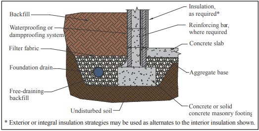
Where drainage is good, a dampproof coating of parging with a permanent bituminous coating has proven to be satisfactory. A portland cement and sand mix (1:3.5 by volume), or Type M or S mortar may be used for the parge coat. The parge coat should be beveled at the top to form a wash, and thickened at the bottom to form a cove between the wall base and top of footing, as shown in Figure 1.

To further increase water penetration resistance, a bituminous coating is applied over the parging. Coal tar or asphalt based bitumens are available in solvent for hot application, or in emulsions for application at ambient temperatures. These coatings can be sprayed, brushed, or trowelled onto the finish coat of parging.

Bentonite Panel Systems

Bentonite is a mineral that swells to many times its original size when wet. Waterproofing panels incorporate dry bentonite encased in kraft paper or fabric. After installation, the bentonite swells up the first time it is exposed to water, expanding between the foundation wall and the backfill, and forming an impervious barrier. The swelling seals small cracks in the foundation wall or punctures in the panels themselves.

To prevent premature hydration bentonite panels must be protected from moisture until they are properly installed and the foundation wall has been backfilled.

Other Systems

There are several systems for which Acceptance Criteria, developed by the ICC Evaluation Service, exist. Cold, liquid-applied, below-grade exterior dampproofing and waterproofing materials should demonstrate compliance with ICC ES AC29 (ref. 5). For rigid, polyethylene, below-grade dampproofing and waterproofing materials, compliance should be shown to ICC-ES AC114 (ref. 6).

Some systems fulfill the requirements of both waterproofing/dampproofing and wall insulation. These systems, however, may not be specified directly in the building code or have an Acceptance Criteria. In these cases, materials should be evaluated both for general waterproofing (or dampproofing) characteristics (such as resistance to hydrostatic pressure, etc.) as well as for criteria specific to the material or system. The Acceptance Criteria listed above can be used as a baseline for a material, although not all requirements may apply to all materials. An engineering evaluation of the product testing results can demonstrate acceptable performance for use as dampproofing or waterproofing.

DRAINAGE

Draining water away from basement walls significantly reduces the pressure the basement wall must resist. This reduces both the potential for cracking and the possibility of water penetration into the basement if there is a failure in the waterproof or dampproof system.

Perforated pipe or drain tiles laid with open joints have proven to be effective at collecting and transporting water away from foundation walls. The invert of drain pipes should be below the top of the floor slab elevation, as shown in Figure 1. The backfill drain should be connected to solid piping to carry the water to natural drainage, a storm sewer, or a sump. For adequate drainage, drains should slope at least in. in 10 ft (10 mm in 3 m).

Drain tile and perforated pipes are typically laid in crushed stone to facilitate drainage. At least 2 in. (51 mm) of washed gravel or free-draining backfill (containing not more than 10% material finer than a No. 4 sieve) should be placed beneath perforated pipes. Drain tiles laid with open joints are more effective when laid on the undisturbed soil where the water begins to accumulate. At least 6 to 12 in. (152 to 305 mm) of the same stone should cover the drain and should extend 12 in. (305 mm) or more beyond the edge of the footing. To prevent migration of fine soils into the drains, filter fabrics are often placed over the gravel.

Drainage pipes may also be placed beneath the slab and connected to a sump. In some cases, pipes are cast in or placed on top of concrete footings at 6 to 8 ft (1.8 to 2.4 m) o.c. to help drain water from the exterior side of the foundation wall.

The backfill material itself also significantly affects water drainage around the wall. The backfill material should be well-draining soil free of large stones, construction debris, organic materials, and frozen earth. Saturated soils, especially saturated clays, should generally not be used for backfill, since wet materials significantly increase the hydrostatic pressure on foundation walls. The top 4 to 8 in. (102 to 203 mm) of backfill should be low permeability soil so rain water is absorbed into the backfill slowly.

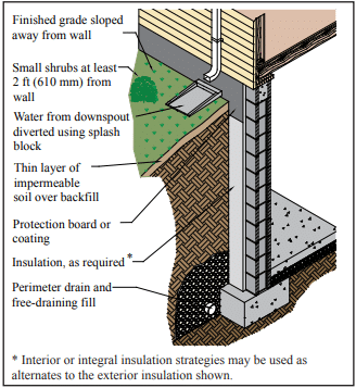
The finished grade should be sloped away from the foundation at least 6 in. within 10 ft (152 mm in 3 m) from the building, as shown in Figure 2. If the ground naturally slopes toward the building, a shallow trench or swale can be installed to direct water runoff away from the building.

Finally, gutters and downspouts should be installed to minimize water accumulation near the foundation. Water exiting downspouts should be directed away from foundation walls using plastic drainage tubing or splash blocks. Roof overhangs, balconies, and porches also shield the soil from direct exposure to rainfall.

CONSTRUCTION

Methods of construction can also impact the watertightness of foundation walls. Properly tooled mortar joints help prevent cracks from forming, and contribute to the watertightness of the finished work. Concave-shaped mortar joints are most effective for resisting water entry. Tooling the mortar compresses the surface to make it more watertight, and also reduces leakage by filling small holes and other imperfections. On the exterior face of the wall, mortar joints may be struck flush if parging will be applied.

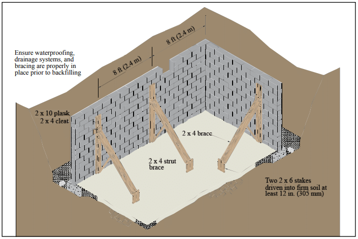
The drainage and waterproof or dampproof system should be inspected prior to backfilling to ensure they are properly placed. Any questionable workmanship or materials should be repaired at this point, because repair is difficult and expensive after backfilling.

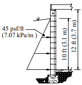
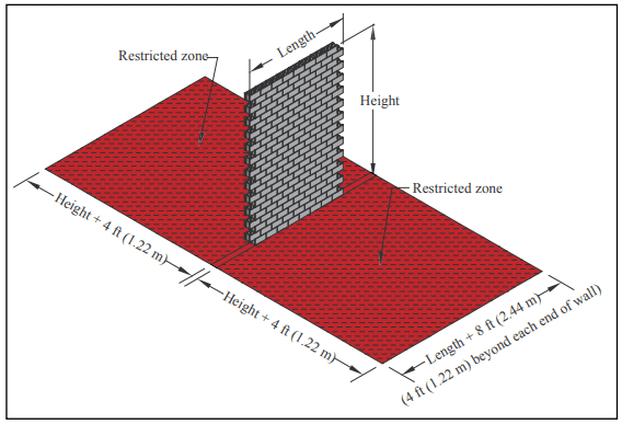
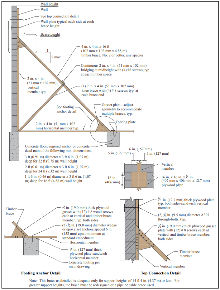
Backfilling methods are important, since improper backfilling can damage foundation walls or the dampproof or waterproof system. Foundation walls should either be properly braced or should have the first floor in place prior to backfilling so the wall is supported against the soil load.

Final grade should be 6 to 12 in. (152 to 305 mm) below the top of the waterproof or dampproof membrane, and should slope away from the foundation wall. In no case should the backfill be placed higher than the design grade line.

These topics are covered in more detail in ref. 7.

LANDSCAPING

Landscaping directly adjacent to the building impacts the amount of water absorbed by the foundation backfill. Particular care should be taken when automatic sprinklers are installed adjacent to foundation walls. Whenever possible, large-rooting shrubs and trees should be placed 10 to 15 ft (3 to 4.6 m) away from foundation walls. Smaller shrubs should be kept at least 2 to 3 ft (0.6 to 0.9 m) from walls. Ground covers help prevent erosion and can extend to the foundation. These elements are illustrated in Figure 2.

Asphalt and concrete parking lots, sidewalks, building aprons, stoops and driveways prevent direct absorption of water into soil adjacent to the foundation, and should be installed to slope away from the building.

REFERENCES

  1. International Building Code. International Codes Council, 2012.
  2. International Residential Code for One- and Two-Family Dwellings. International Code Council, 2012.
  3. Standard Specification for Packaged, Dry, Combined Materials for Surface Bonding Mortar, ASTM C887-05(2010) . ASTM International, Inc., 2010.
  4. Basement Manual—Design & Construction Using Concrete Masonry, CMU-MAN-002-01, Concrete Masonry & Hardscapes Association, 2001.
  5. Acceptance Criteria for Cold, Liquid-Applied, Below-Grade, Exterior Damproofing and Waterproofing Materials, ICC ES AC29. International Code Council, 2011.
  6. Acceptance Criteria for Rigid, Polyethylene, Below-Grade, Damproofing and Wall Waterproofing Material, ICC-ES AC114. International Code Council, 2011.
  7. Concrete Masonry Basement Wall Construction, TEK 03-11, Concrete Masonry & Hardscapes Association, 2001.


Strength Design of Reinforced Concrete Masonry Foundation Walls

INTRODUCTION

Although concrete masonry foundation walls can be constructed without reinforcing steel, reinforcement may be required for walls supporting large soil backfill loads. The strength design provisions found in Chapter 3 of Building Code Requirements for Masonry Structures (ref. 1) typically provides increased economy over the allowable stress design method, as thinner walls or larger reinforcing bar spacings often result from a strength design analysis. Strength design criteria are presented in detail in TEK 14-04B, Strength Design Provisions for Concrete Masonry (ref. 2).

DESIGN LOADS

Soil imparts lateral loads on foundation walls. The load is assumed to increase linearly with depth, resulting in a triangular load distribution on the wall. This lateral soil load is expressed as an equivalent fluid pressure, with units of pounds per square foot per foot of depth (kN/m²/m). For strength design analysis, this lateral soil pressure is increased by multiplying by a load factor, which provides a factor of safety against overload conditions. The maximum moment on the wall depends on the total wall height, the soil backfill height, the wall support conditions, the factored soil load, the existence of any surcharges on the soil and the presence of saturated soils.

Foundation walls also provide support for the structure above the foundation, transferring vertical loads to the footing. Vertical compression counteracts flexural tension, increasing the wall’s resistance to flexure. In low-rise construction, these vertical loads are typically small in relation to the compressive strength of the concrete masonry. Vertical load effects are not addressed in this TEK.

DESIGN TABLES

Tables 1 through 4 present reinforcement schedules for 6, 8, 10 and 12-in. (152, 203, 254 and 305-mm) walls, respectively. Additional reinforcement alternatives may be appropriate, and can be verified with an engineering analysis. Walls from 8 to 16 ft (2.4 to 4.9 m) high and soil pressures of 30, 45 and 60 psf/ft (4.7, 7.0, and 9.4 kN/m²/m) are included.

The effective reinforcement depth, d, assumed for the analyses are practical values, taking into account variations in face shell thickness, a range of reinforcing bar sizes, minimum required grout cover and construction tolerances for placing the reinforcement.

The following assumptions also apply to the values in Tables 1 through 4:

  1. there are no surcharges on the soil adjacent to the wall,
  2. there are negligible axial loads on the wall,
  3. the wall is simply supported at top and bottom,
  4. the wall is grouted at cells containing reinforcement (although solid grouting is acceptable),
  5. section properties are based on minimum face shell and web thickness requirements of ASTM C 90 (ref. 3),
  6. the specified compressive strength of masonry, f’m, is 1500 psi (10.3 MPa),
  7. Grade 60 (413 MPa) reinforcement,
  8. reinforcement requirements listed account for a soil load factor of 1.6 (ref. 6),
  9. the maximum width of the compression zone is limited to six times the wall thickness, or a 72 in. (1,829 mm) vertical bar spacing, whichever is smaller,
  10. reinforcing steel is placed toward the tension (interior) face of the wall (as shown in Figure 1), and
  11. the soil is well drained to preclude the presence of saturated soil.

DESIGN EXAMPLE

Wall: 12-in. (305 mm) thick concrete masonry foundation wall, 12 ft (3.66 m) high

Soil: equivalent fluid pressure is 45 psf/ft (7.0 kN/m²/m) (excluding soil load factors), 10 ft (3.05 m) backfill height

Using Table 4, the wall can be adequately reinforced using No. 9 bars at 72 in. o.c. (M# 29 at 1,829 mm).

CONSTRUCTION ISSUES

This section discusses those issues which directly relate to structural design assumptions. See TEK 03-11, Concrete Masonry Basement Wall Construction and TEK 05-03A, Concrete Masonry Foundation Wall Details (refs. 4, 5) for more complete information on building concrete masonry foundation walls.

Figure 1 illustrates wall support conditions, drainage and protection from water. Before backfilling, the floor diaphragm must be in place, or the wall must be properly braced to resist the soil load. Ideally, the backfill should be free-draining granular material, free from expansive soils or other deleterious materials.

The assumption that there are no surcharges on the soil means that heavy equipment should not be operated directly adjacent to any basement wall system. In addition, the backfill materials should be placed and compacted in several lifts. Care should be taken when placing backfill materials to prevent damaging the drainage, waterproofing or exterior insulation systems.

REFERENCES

  1. Building Code Requirements for Masonry Structures, ACI 530-02/ASCE 5-02/TMS 402-02. Reported by the Masonry Standards Joint Committee, 2002.
  2. Strength Design Provisions for Concrete Masonry, TEK 14-04B, Concrete Masonry & Hardscapes Association, 2008.
  3. Standard Specification for Loadbearing Concrete Masonry Units, ASTM C 90-03. ASTM International, 2003.
  4. Concrete Masonry Basement Wall Construction, TEK 0311, Concrete Masonry & Hardscapes Association, 2001.
  5. Concrete Masonry Foundation Wall Details, TEK 05-03A, Concrete Masonry & Hardscapes Association, 2003.
  6. Minimum Design Loads for Buildings and Other Structures, ASCE 7-02. American Society of Civil Engineers, 2002.


Allowable Stress Design of Concrete Masonry Foundation Walls

INTRODUCTION

Basements provide: economical living, working and storage areas; convenient spaces for mechanical equipment; safe havens during tornadoes and other violent storms; and easy access to plumbing and ductwork. Concrete masonry is well suited to basement and foundation wall construction due to its inherent durability, compressive strength, economy, and resistance to fire, termites, and noise.

Traditionally, residential basement walls have been constructed of plain (unreinforced) concrete masonry, often designed empirically. Walls over 8 ft (2.4 m) high or with larger soil loads are typically designed using reinforced concrete masonry or using design tables included in building codes such as the International Building Code (ref. 4).

DESIGN LOADS

Soil imparts a lateral load on foundation walls. For design, the load is traditionally assumed to increase linearly with depth resulting in a triangular load distribution. This lateral soil load is expressed as an equivalent fluid pressure, with units of pounds per square foot per foot of depth (kPa/m). The maximum force on the wall depends on the total wall height, soil backfill height, wall support conditions, soil type, and the existence of any soil surcharges. For design, foundation walls are typically assumed to act as simple vertical beams laterally supported at the top and bottom.

Foundation walls also provide support for the structure above, transferring vertical loads to the footing. When foundations span vertically, this vertical compression counteracts flexural tension, increasing the wall’s resistance to flexure. In low-rise construction, these vertical loads are typically small in relation to the compressive strength of concrete masonry. Further, if the wall spans horizontally, vertical compression does not offset the flexural tension. Vertical load effects are not included in the tables and design example presented in this TEK (references 2 and 3 include vertical load effects).

EMPIRICAL DESIGN

The empirical design method uses historical experience to proportion and size masonry elements. Empirical design is often used to design concrete masonry foundation walls due to its simplicity and history of successful performance.

Table 1 lists the allowable backfill heights for 8, 10 and 12-inch (203, 254 and 305 mm) concrete masonry foundation walls. Table 1 may be used for foundation walls up to 8 feet (2.4 m) high under the following conditions (ref. 1):

  1. terrain surrounding the foundation wall is graded to drain surface water away from foundation walls,
  2. backfill is drained to remove ground water away from foundation walls,
  3. tops of foundation walls are laterally supported prior to backfilling,
  4. the length of foundation walls between perpendicular masonry walls or pilasters is a maximum of 3 times the foundation wall height,
  5. the backfill is granular and soil conditions in the area are non-expansive,
  6. masonry is laid in running bond using Type M or S mortar, and
  7. units meet the requirements of ASTM C 90 (ref. 6).

Where these conditions cannot be met, the wall must be engineered using either an allowable stress design (see following section) or strength design procedure (see ref. 5).

WALL DESIGN

Tables 2 through 4 of this TEK have been rationally designed in accordance with the allowable stress design provisions of Building Code Requirements for Masonry Structures (ref. 1) and therefore meet the requirements of the International Building Code even though the latter limits reinforcment spacing to 72 in. (1829 mm) when using their tables. Additional reinforcement alternatives may be appropriate and can be verified with an engineering analysis.

Tables 2, 3 and 4 list reinforcement options for 8, 10 and 12-in. (203, 254 and 305-mm) thick walls, respectively. The effective depths of reinforcement, d, (see Table notes) used are practical values, taking into account variations in face shell thickness, a range of bar sizes, minimum required grout cover, and construction tolerances for placing the reinforcing bars.

Tables 2 through 4 are based on the following:

  1. no surcharges on the soil adjacent to the wall and no hydrostatic pressure,
  2. negligible axial loads on the wall,
  3. wall is simply supported at top and bottom,
  4. wall is grouted only at reinforced cells,
  5. section properties are based on minimum face shell and web thicknesses in ASTM C 90 (ref. 6),
  6. specified compressive strength of masonry, f’m, is 1,500 psi (10.3 MPa),
  7. reinforcement yield strength, fy, is 60,000 psi (414 MPa),
  8. modulus of elasticity of masonry, Em, is 1,350,000 psi (9,308 MPa),
  9. modulus of elasticity of steel, Es, is 29,000,000 psi (200,000 MPa),
  10. maximum width of compression zone is six times the wall thickness (where reinforcement spacing exceeds this distance, the ability of the plain masonry outside the compression zone to distribute loads horizontally to the reinforced section was verified assuming two-way plate action),
  11. allowable tensile stress in reinforcement, Fs, is 24,000 psi (165 MPa),
  12. allowable compressive stress in masonry, Fb, is f’m (500 psi, 3.4 MPa),
  13. grout complies with ASTM C 476 (2,000 psi (14 MPa) if property spec is used) (ref. 7), and
  14. masonry is laid in running bond using Type M or S mortar and face shell mortar bedding.

DESIGN EXAMPLE

Wall: 12-inch (305 mm) thick, 12 feet (3.7 m) high.

Loads: equivalent fluid pressure of soil is 45 pcf (7.07 kPa/ m), 10 foot (3.1 m) backfill height. No axial, seismic, or other loads.

Using Table 4, #8 bars at 40 in. (M 25 at 1016 mm) o.c. are sufficient.

CONSTRUCTION ISSUES

This section is not a complete construction guide, but rather discusses those issues directly related to structural design assumptions. Figures 1 and 2 illustrate typical wall support conditions, drainage, and water protection.

Before backfilling, the floor diaphragm must be in place or the wall must be properly braced to resist the soil load. In addition to the absence of additional dead or live loads following construction, the assumption that there are no surcharges on the soil also means that heavy equipment should not be operated close to basement wall systems that are not designed to carry the additional load. In addition, the backfill materials should be placed and compacted in several lifts, taking care to prevent wall damage. Care should also be taken to prevent damaging the drainage, waterproofing, or exterior insulation systems, if present.

REFERENCES

  1. Building Code Requirements for Masonry Structures, ACI 530-99/ASCE 5-99/TMS 402-99. Reported by the Masonry Standards Joint Committee, 1999.
  2. International Building Code. International Code Council, 2000.
  3. Strength Design of Reinforced CM Foundation Walls, TEK 15-02B, Concrete Masonry & Hardscapes Association, 2004.
  4. Standard Specification for Loadbearing Concrete Masonry Units, ASTM C 90-01. American Society for Testing and Materials, 2001.
  5. Standard Specification for Grout Masonry, ASTM C476- 01. American Society for Testing and Materials, 2001.

Insulating Conrete Masonry Walls

INTRODUCTION

The variety of concrete masonry wall constructions provides for
a number of insulating strategies, including: interior insulation,
insulated cavities, insulation inserts, foamed-in-place insulation,
granular fills in block core spaces, and exterior insulation
systems. Each masonry wall design has different advantages
and limitations with regard to each of these insulation
strategies. The choice of insulation will depend on the desired
thermal properties, climate conditions, ease of construction,
cost, and other design criteria. Note that insulation position
within the wall can impact dew point location, and hence affect
the condensation potential. See TEK 06-17B, Condensation
Control in Concrete Masonry Walls
(ref. 1) for more detailed
information. Similarly, some insulations can act as an air barrier
when installed continuously and with sealed joints. See TEK
06-14B, Control of Infiltration in Concrete Masonry Walls, (ref.
2) for further information.

MASONRY THERMAL PERFORMANCE

The thermal performance of a masonry wall depends on its steady state thermal characteristics (described by R-value or U-factor) as well as the thermal mass (heat capacity) characteristics of the wall. The steady state and mass performance are influenced by the size and type of masonry unit, type and location of insulation, finish materials, and density of masonry. Lower density concrete masonry mix designs result in higher R-values (i.e., lower U-factors) than higher density concretes. Thermal mass describes the ability of materials to store heat. Because of its comparatively high density and specific heat, masonry provides very effective thermal storage. Masonry walls remain warm or cool long after the heat or airconditioning has shut off. This, in turn, effectively reduces heating and cooling loads, moderates indoor temperature swings, and shifts heating and cooling loads to off-peak hours. Due to the significant benefits of concrete masonry’s inherent thermal mass, concrete masonry buildings can provide similar performance to more heavily insulated frame buildings.

The benefits of thermal mass have been incorporated into energy code requirements as well as sophisticated computer models. Energy codes and standards such as the International Energy Conservation Code (IECC) (ref. 5) and Energy Efficient Standard for Buildings Except Low-Rise Residential Buildings, ASHRAE/IESNA Standard 90.1 (ref. 6), permit concrete masonry walls to have less insulation than frame wall systems to meet the energy requirements.

Although the thermal mass and inherent R-value/U-factor of concrete masonry may be enough to meet energy code requirements (particularly in warmer climates), concrete masonry walls often require additional insulation. When they do, there are many options available for insulating concrete masonry construction. When required, concrete masonry can provide walls with R-values that exceed code minimums (see refs. 3, 4). For overall project economy, however, the industry suggests a parametric analysis to determine reasonable insulation levels for the building envelope elements.

The effectiveness of thermal mass varies with factors such as climate, building design and insulation position. The effects of insulation position are discussed in the following sections. Note, however, that depending on the specific code compliance method chosen, insulation position may not be reflected in a particular code or standard.

There are several methods available to comply with the energy requirements of the IECC. One of the options, the IECC prescriptive R-values (IECC Table 502.2(1)) calls for “continuous insulation” on concrete masonry and other mass walls. This refers to insulation uninterrupted by furring or by the webs of concrete masonry units. Examples include rigid insulation adhered to the interior of the wall with furring and drywall applied over the insulation, continuous insulation in a masonry cavity wall, and exterior insulation and finish systems. If the concrete masonry wall will not include continuous insulation, there are several other options to comply with the IECC requirements—concrete masonry walls are not required to have continuous insulation in order to meet the IECC. See TEK 06-12E, Concrete Masonry in the 2012 Edition of the IECC and TEK 06-04B, Energy Code Compliance Using COMcheck (refs. 7, 8).

INTERIOR INSULATION

Interior insulation refers to insulation applied to the interior side of the concrete masonry, as shown in Figure 1. The insulation may be rigid board (extruded or expanded polystyrene or polyisocyanurate), closed-cell spray polyurethane foam, cellular glass, fibrous batt, or fibrous blown-in insulation (note, however, that fibrous insulation is susceptible to moisture). The interior wall surface is usually finished with gypsum wallboard or paneling.

Interior insulation allows for exposed masonry on the exterior, but isolates the masonry from the building’s interior and so may reduce the effects of thermal mass.

With rigid board insulation, an adhesive is used to temporarily hold the insulation in place while mechanical fasteners and a protective finish are applied. Furring may be used and held away from the face of the masonry with spacers. The space created by the spacers provides moisture protection, as well as a convenient and economical location for additional insulation, wiring or pipes.

As an alternative, wood or metal furring can be installed with insulation placed between the furring. The furring size is determined by the type of insulation and R-value required. Because the furring penetrates the insulation, the furring properties must be considered in analyzing the wall’s thermal performance. Steel penetrations through insulation significantly affect the thermal resistance by conducting heat from one side of the insulation to the other. Although not as conductive as metal, the thermal resistance of wood and the cross sectional area of the wood furring penetration should be taken into account when determining overall R-values. See TEK 06-13B, Thermal Bridges in Wall Construction (ref. 9) for more information.

Closed cell spray polyurethane foam is typically installed between interior furring. The foam is applied as a liquid and expands in-place. Proper training helps ensure a quality installation. The foam is resistant to both air and water vapor transmission.

When using interior insulation, concrete masonry can accommodate both vertical and horizontal reinforcement with partial or full grouting without interrupting the insulation layer. The durability, weather resistance, and impact resistance of the exterior of a wall remain unchanged with the addition of interior insulation. Impact resistance on the interior surface is determined by the interior finish.

INTEGRAL INSULATION

Figure 2 illustrates some typical integral insulations in single-wythe masonry walls. Integral insulation refers to insulation placed between two layers of thermal mass. Examples include insulation placed in concrete masonry cores and continuous insulation in a masonry cavity wall (note that an insulated masonry cavity wall can also be considered as exterior insulation if the thermal mass effect of the veneer is disregarded).

With integral insulation, some of the thermal mass (masonry) is directly in contact with the indoor air, which provides excellent thermal mass benefits, while allowing exposed masonry on both the exterior and interior.

Multi-wythe cavity walls contain insulation between two wythes of masonry. The continuous cavity insulation minimizes thermal bridging. The cavity width can be varied to achieve a wide range of R-values. Cavity insulation can be rigid board, closed cell spray polyurethane foam, or loose fill. To further increase the thermal performance, the cores of the backup wythe may be insulated.

When rigid board insulation is used in the cavity, the inner masonry wythe is typically completed first. The insulation is precut or scored by the manufacturer to facilitate placement between the wall ties. The board insulation may be attached with an adhesive or mechanical fasteners. Tight joints between the insulation boards maximize the thermal performance and reduce air leakage. In some cases, the joints between boards are set into an expandable bead of sealant, or caulked or taped to act as an air barrier.

Integral insulations placed in masonry cores are typically molded polystyrene inserts, foams, or expanded perlite or vermiculite granular fills. As for the furring used for interior insulation, the thermal resistance of the concrete masonry webs and any grouted cores should be accounted for when determining the thermal performance of the wall (see TEK 06-02C, ref. 3, for tabulated R-values of walls with core insulation). When using core insulation, the insulation should occupy all ungrouted core spaces (although some rigid inserts are configured to accommodate reinforcing steel and grout in the same cell).

Foamed-in-place insulation is installed in masonry cores after the wall is completed. The installer either fills the cores from the top of the wall or pumps the foam through small holes drilled into the masonry. Foams may be sensitive to temperature, mixing conditions, or other factors. Therefore, manufacturers’ instructions should be carefully followed to avoid excessive shrinkage due to improper mixing or placing of the foam.

Polystyrene inserts may be placed in the cores of conventional masonry units or used in specially designed units. Inserts are available in many shapes and sizes to provide a range of R-values and accommodate various construction conditions. In pre-insulated masonry, the inserts are installed by the manufacturer. Inserts are also available which are installed at the construction site.

Specially designed concrete masonry units may incorporate reduced height webs to accommodate inserts in the cores. Such webs also reduce thermal bridging through masonry, since the reduced web area provides a smaller cross-sectional area for heat flow through a wall. To further reduce thermal bridging, some manufacturers have developed concrete masonry units with two cross webs rather than three.

Vertical and horizontal reinforcement grouted into the concrete masonry cores may be required for structural performance. Cores to be grouted are isolated from cores to be insulated by placing mortar on the webs to confine the grout. Granular or foam insulation is placed in the ungrouted cores within the wall. Thermal resistance is then determined based on the average R-value of the wall area (see TEK 06-02C, ref. 3, for an explanation and example calculation). Some rigid inserts are configured to accommodate reinforcing steel and grout, to provide both thermal protection and structural performance. When inserts are used in grouted construction, the coderequired minimum grout space dimensions must be met (see TEK 03-02A, ref. 10).

Granular fills are placed in masonry cores as the wall is laid up. Usually, the fills are poured directly from bags into the cores. A small amount of settlement usually occurs, but has a relatively small effect on overall performance. Granular fills tend to flow out of any holes in the wall system. Therefore, weep holes should have noncorrosive screens on the interior or wicks to contain the fill while allowing water drainage. Bee holes or other gaps in the mortar joints should be filled. In addition, drilled-in anchors placed after the insulation require special installation procedures to prevent loss of the granular fill.

EXTERIOR INSULATION

Exterior insulated masonry walls are walls that have insulation on the exterior side of the thermal mass. In these walls, continuous exterior insulation envelopes the masonry, minimizing the effect of thermal bridges. This places the thermal mass inside the insulation layer. Exterior insulation keeps masonry directly in contact with the interior conditioned air, providing the most thermal mass benefit of the three insulation strategies.

Exterior insulation also reduces heat loss and moisture movement due to air leakage when joints between the insulation boards are sealed. Exterior insulation negates the aesthetic advantage of exposed masonry. In addition, the insulation requires a protective finish to maintain the durability, integrity, and effectiveness of the insulation.

For exterior stucco installation, a reinforcing mesh is applied to reinforce the finish coating, improving the crack and impact resistance. Fiberglass mesh, corrosion-resistant woven wire mesh or metal lath is used for this purpose. After the mesh is installed, mechanical fasteners are placed through the insulation, to anchor securely into the concrete masonry. Mechanical fasteners can be either metal or nylon, although nylon limits the heat loss through the fasteners.

After the insulation and reinforcing mesh are mechanically fastened to the masonry, a finish coating is troweled onto the surface. This surface gives the wall its final color and texture, as well as providing weather and impact resistance.

BELOW GRADE APPLICATIONS

Below grade masonry walls typically use single-wythe wall construction, which can accommodate interior, integral, or exterior insulation.

Exterior or integral insulation is effective in moderating interior temperatures and in shifting peak energy loads. The typical furring used for interior insulation provides a place to run electric and plumbing lines, as well as being convenient for installing drywall or other interior finishes.

When using exterior or integral insulation strategies, architectural concrete masonry units provide a finished surface on the interior. Using smooth molded units at the wall base facilitates screeding the slab. After casting the slab, a molding strip, also serving as an electric raceway, can be placed against the smooth first course. The remainder of the wall may be constructed of smooth, split-face, split ribbed, ground faced, scored or other architectural concrete masonry units.

Insulation on the exterior of below grade portions of the wall is temporarily held in place by adhesives until the backfill is placed. That portion of the rigid board which extends above grade should be mechanically attached and protected.

REFERENCES

  1. Condensation Control in Concrete Masonry Walls, TEK 06-17B, Concrete Masonry & Hardscapes Association, 2011.
  2. Control of Infiltration in Concrete Masonry Walls, TEK 06-14A, Concrete Masonry & Hardscapes Association, 2011.
  3. R-Values and U-Factors of Single Wythe Concrete Masonry Walls, TEK 06-02C, Concrete Masonry & Hardscapes Association, 2013.
  4. R-Values of Multi-Wythe Concrete Masonry Walls, TEK 06-01C, Concrete Masonry & Hardscapes Association, 2013.
  5. International Energy Conservation Code. International Code Council, 2003, 2006 and 2009.
  6. Energy Efficient Standard for Buildings Except LowRise Residential Buildings, ASHRAE/IESNA Standard 90.1. American Society of Heating, Refrigerating and Air Conditioning Engineers and Illuminating Engineers Society, 2001, 2004 and 2007.
  7. International Energy Conservation Code and Concrete Masonry, TEK 6-12C. Concrete Masonry & Hardscapes Association, 2007.
  8. Energy Code Compliance Using COMcheck TEK 06-04B, Concrete Masonry & Hardscapes Association, 2012.
  9. Thermal Bridges in Wall Construction, TEK 06-13B, Concrete Masonry & Hardscapes Association, 2010.
  10. Grouting Concrete Masonry Walls, TEK 03-02A, Concrete Masonry & Hardscapes Association, 2005.

Bracing Concrete Masonry Walls Under Construction

INTRODUCTION

Building codes typically place responsibility for providing a reasonable level of life safety for workers during construction on the erecting contractor. Various methods are employed to protect workers while newly constructed masonry walls are curing and/or until the roof or other structural supports are in place. This TEK provides guidelines for masonry wall stability to resist the lateral loading effects of wind during construction. It is based on principles set forth in the Council for Masonry Wall Bracing’s Standard Practice for Bracing Masonry Walls Under Construction (ref. 1), but has been updated in accordance with the design provisions of the 2011 Building Code Requirements for Masonry Structures (MSJC, ref. 2).

When other lateral loads such as impact, seismic, scaffolding, and lateral earth pressure are present, they need to be considered and evaluated separately. The Walls Subject to Backfilling section at the end of this TEK discusses bracing and support of basement walls during backfilling operations.

WALLS SUBJECT TO WIND LOADS

There are several strategies and considerations for protecting life safety on the jobsite. These include internal bracing, external bracing and evacuation zones. The combination of strategies appropriate for a particular job may depend on the type of masonry construction, masonry wall heights, the time elapsed since construction, and wind speeds at the site.

The industry term “internal bracing” is relatively new. Internal bracing refers to the stability of a masonry assembly to resist wind loads through self-weight and allowable flexural stresses within the masonry.

The use of evacuation zones recognizes that it may be impractical to prevent the collapse of a masonry wall during construction when subjected to extreme loading conditions and that life safety is the primary concern. At prescribed wind speeds (taken as three-second gusts measured at the job site), the wall and the area around it is evacuated. The critical wind speed resulting in evacuation depends on the age of the wall being constructed and involves the three terms: “restricted zone,” “initial period,” and “intermediate period.”

Restricted Zone

The restricted zone is the area on each side of a wall subject to the effect of a masonry wall collapse. It is defined by a length equal to the height of the constructed wall plus 4 ft (1.22 m) on both sides of the wall, and a width equal to the wall length plus 4 ft (1.22 m) on both ends of the wall, as shown in Figure 1. When wind speeds exceed those allowed during the initial and intermediate periods, there is a chance that the masonry wall could fail, and the restricted zone must be evacuated in order to ensure life safety.

Initial Period

The initial period is the period of time, not to exceed 24 hours, during which the masonry is being laid above its base or highest line of bracing, and at the end of which required bracing is installed. During this period, the mortar is assumed to have no strength and wall stability is accomplished from the masonry self-weight only. Based on this assumption and a wind speed limit of 20 mph (8.9 m/s), walls can be built to the heights shown in Table 1 without bracing during the initial period. If wind speeds exceed 20 mph (8.9 m/s) during the initial period, work on the wall must cease and the restricted zone on both sides of the wall must be evacuated. Evacuation for walls up to 8 ft (2.44 m) above grade is not necessary until wind speeds reach 35 mph (15.6 m/s) in keeping with a long-standing OSHA requirement.

Intermediate Period

The intermediate period is the period of time following the initial period but before the wall is connected to the elements that provide its final lateral support. The design wind speed is 40 mph (17.9 m/s) 3-second gust for brace design. When the wind speed exceeds 35 mph (15.6 m/s), the restricted zone must be evacuated. The difference of 5 mph (2.2 m/s) is to allow workers time to evacuate the area.

During the intermediate period, the masonry is assumed to have one-half of its design compressive strength and plain masonry allowable flexural stresses are taken as two-thirds of the design value given in the 2011 MSJC (ref. 2). The masonry structural capacity then can be determined using these reduced values in accordance with the provisions of the Code (see ref. 3 for more information).

There are several methods of providing an acceptable level of life safety for masons and others working on the construction site. They are:

  1. bracing to a design wind speed of 40 mph (17.9 m/s), 3-second gust and evacuating if the wind speed exceeds 35 mph (15.6 m/s), 3-second gust,
  2. alternative bracing designs and methods approved, sealed, and signed by a registered professional engineer if supported by data representing field conditions, and
  3. an early warning and evacuation program when the masonry is designed to resist a wind speed of 5 mph (2.2 m/s) greater than the designated evacuation wind speed. The wind speed measurement must be made by an instrument with a ± 2 mph (0.89 m/s) accuracy.

Traditionally, bracing and evacuation of the restricted zones has also been based on wind speeds lower that 35 mph (15.6 m/s). As such, Table 2 addresses evacuation wind speeds of 15 and 25 mph (6.7 and 11.2 m/s) in addition to the 35 mph (15.6 m/s) evacuation wind speed. Many jurisdictions will accept the lower wind speed criteria but users should first confirm acceptability with their local building official and/or OSHA representative before using them.

Table 2 lists maximum unbraced wall heights when early warning with an evacuation program is implemented. Design wind speeds for the heights in Table 2 are for 5 mph (2.2 m/s) greater than the evacuation speed to allow time for the masons to get off the scaffolding and evacuate the restricted zone.

Figure 2 shows a wood brace detail for support heights up to 14′-4″ (4.37 m) maximum. Proprietary pipe bracing systems and cable systems are also available for all heights shown in Table 2—see manufacturer’s recommendations for details.

Research has shown that properly designed and constructed reinforcement splices can achieve up to 75% of the specified yield stress of the reinforcing steel at 12 hours and 100% at 24 hours (ref. 1). Therefore, the full capacity of splices may be used after grout has been in place 24 hours. Alternatively, the full splice capacity can be used after only 12 hours if the design lap length is increased by one-third. Splice criteria is as follows for Grade 60 reinforcement:

  • 48 bar diameters for grout that has been in place 24 hours or more,
  • 64 bar diameters for grout that has been in place 12 hours or more but less than 24 hours.

Connections to masonry can be designed using the previously described reduced masonry strengths and design formulas. As an alternate, restricted working loads for post- drilled anchors as reported in the manufacturer’s literature may be used.

Design Example

Determine the bracing requirements for a 22 ft (6.71 m) tall wall constructed with 8 in. (203 mm) concrete masonry having a density of 110 lb/ft3 (1762 kg/m3) and reinforced with No. 5 bars at 32 in. (M#16 at 813 mm) o.c. using 30 in. (762 mm) splice lengths (i.e., 48 bar diameters). Mortar is masonry cement Type S, control joints are spaced at 24′-8″ (7.52 m), and flashing is at the base of the wall only (unbonded condition).

Initial Period

From Table 1:

Maximum unsupported height = 10′-0″ (3.05 m). (These initial period provisions apply to all of the options that follow.)

Intermediate Period—Unbraced Option

From Table 2:

Alternate 1: Evacuation wind speed of 15 mph (6.7 m/s).

NOTE: Although this type of option has historically been accepted, the designer should verify acceptance with the local building official and/or OSHA representative.

Unreinforced wall:

Maximum height above grade, unbonded = 10′-0″ (3.05 m)

Maximum height above grade or line of support, bonded = 23′-0″ (7.01 m)

Reinforced wall:

Maximum height, bonded or unbonded = 23′-4″ (7.11 m) for No. 5 at 48 in. (M#16 at 1.22 m)

This is conservative, because the wall in this example has reinforcement spaced closer than 48 in. (1.22 m).

Strategy:

Build the wall to a height of 10′-0″ (3.05 m) the first day (initial period).

The maximum height for an unbonded condition during the intermediate period is 10′-0″ (3.05 m) for this wind speed, therefore neither bracing nor grouting is required for the 10′-0″ (3.05 m) height during the intermediate period.

If the wall is reinforced and grouted, it can support a total height of 23′-4″ (7.11 m). Therefore, if the first 10′-0″ (3.05 m) is reinforced and grouted, another 10′-0″ (3.05 m) (initial period limit) could be built 24 hours after grout placement if the standard 30 in. (1,016 mm) reinforcement splice is used (or after 12 hours with a 40 in. (762 mm) splice). The 10′- 0″ (3.05 m) height is less than the 23′-0″ (7.01 m) unbraced limit for the bonded unreinforced intermediate period and the total 20′-0″ (6.10 m) of constructed wall height is less than the reinforced limit of 23′-4″ (7.11 m).

The next day, the top 2 ft (0.61 m) of masonry can be added, because the initial period limit of 10′-0″ (3.05 m) is met, the maximum unreinforced bonded limit of 23′-0″ (7.01 m) is met, and the reinforced limit of 23′-4″ (7.11 m) is met. Therefore, the wall can be built in this manner without external bracing.

NOTE: This option requires early warning and evacuation when wind speeds reach 15 mph (6.7 m/s) 3-second gust. This may not be practical in all areas.

Alternate 2: Design for an evacuation wind speed of 35 mph (15.6 m/s).

Unreinforced wall:

Maximum height above grade, unbonded = 8′-0″ (2.44 m) at ground level (see Table 2 note G), 2′-8″ (0.81 m) otherwise, Maximum height above grade or line of support, bonded = 10′-0″ (3.05 m)

Maximum vertical spacing between braces, bonded = 12′-4″ (3.75 m)

Maximum vertical height above brace, bonded = 6′-0″ (1.82 m)

Reinforced wall:

Maximum height above grade or line of support, bonded 23′-4″ (7.11 m)

Maximum vertical spacing between braces, bonded = 28′-0″ (8.53 m)

Maximum vertical height above brace, bonded = 14′-0″ (4.26 m)

Strategy:

Build the wall to a height of 10 ft (3.05 m) the first day (Table 1: initial period limit is 10′-0″ (3.05 m)). Grout that lift the same day, which after the curing period (12 or 24 hours depending on the splice length used) can support a cantilever height of 23′-4″ (7.11 m).

Then, build an additional section of wall of 6′-0″ (1.82 m) high, grout it and brace it at no lower than the 8′-0″ (2.43 m) level, because only 14′-0″ (4.26 m) of the reinforced 22 ft (6.71 m) wall can extend above the brace.

The next or following days, finish the rest of the wall and grout that portion the same day. (Note the first two sections each could have been done in 8′-0″ (2.44 m) heights as well.)

The brace will need to stay in place until the permanent support (roof or floor) is in place. Note that when counting reinforced internal bracing, the wall must be grouted the same day and the restricted zone vacated for the next 12 or 24 hours, depending on the splice length used.

NOTE: Refer to the International Masonry Institute’s Internal Bracing Design Guide for Masonry Walls Under Construction (ref. 4). That demonstrates how to effectively use low-lift grouting for internal bracing, as each lift that is grouted can be considered reinforced and able to withstand higher loadings at the bottom of the wall where stresses are highest.

WALLS SUBJECT TO BACKFILLING

Unless concrete masonry basement walls are designed and built to resist lateral earth pressure as cantilever walls, they should not be backfilled until the first floor construction is in place and anchored to the wall or until the walls are adequately braced. Figure 3 illustrates one type of temporary lateral bracing being used in the construction of concrete masonry basement walls. Heavy equipment, such as bulldozers or cranes, should not be operated over the backfill during construction unless the basement walls are appropriately designed for the higher resulting loads.

Ordinarily, earth pressures assumed in the design of basement walls are selected on the assumption that the backfill material will be in a reasonably dry condition when placed. Because lateral earth pressures increase as the moisture content of the earth increases, basement walls should not be backfilled with saturated materials nor should backfill be placed when any appreciable amount of water is standing in the excavation. Similarly, water jetting or soaking should never be used to expedite consolidation of the backfill.

Care should be taken to avoid subjecting the walls to impact loads, as would be imparted by earth sliding down a steep slope and hitting the wall. This could also damage waterproofing, dampproofing, or insulation applied to the walls. Also, if needed, a concrete masonry unit can be left out at the bottom of a wall to prevent an unbalanced accumulation of water. The unit can be replaced before backfilling.

REFERENCES

  1. Standard Practice for Bracing Masonry Walls Under Construction. Council for Masonry Wall Bracing, December 2012.
  2. Building Code Requirements for Masonry Structures, TMS 402-11/ACI 530-11/ASCE 5-11. Reported by the Masonry Standards Joint Committee, 2011.
  3. Allowable Stress Design of Concrete Masonry Based on the 2012 IBC and 2011 MSJC, TEK 14-07C. Concrete Masonry & Hardscapes Association, 2013.
  4. Internal Bracing Design Guide for Masonry Walls Under Construction. International Masonry Institute, May 2013 (available free at www.imiweb.org).
  5. Basement Manual: Design and Construction Using Concrete Masonry, CMU-MAN-002-01, Concrete Masonry & Hardscapes Association, 2001.