The current trend of urban renewal and infill has sparked a high volume of new low-rise masonry residences. These structures come in many forms, but quite often they employ the use of load-bearing concrete masonry walls supporting a wood floor system. These new buildings are largely derivative of the historic load bearing masonry “brownstone” or “three flat” structures of old. This guide is intended to assist contractors and architects to give this building type a modern approach to detailing.
FLOOR SYSTEM CONNECTIONS
When designing low-rise loadbearing structures, the connection detail between the floor system and the wall system is critical for achieving a watertight structure. Much of this TEK will deal with which strategy should be utilized in connecting a wood floor system to a masonry load-bearing wall. Connection methods covered are joist hangers, beam pockets and ledger beam details. Other floor systems are used in low-rise construction that are not addressed here – see 05-07A for further information (ref. 2).
BRICK AND BLOCK COMPOSITE WALL DETAILS
Quite often, the front facade of these structures is composed of brick to give the building a more residential, more human scale. One way to construct a brick and block wall is to separate the two wythes with an airspace, creating a cavity wall. Another is to use a composite wall design. The composite wall consists of an exterior wythe of brick directly mortared or grouted and tied to an inner wythe of CMU. The collar joint between the two wythes should be 100% solid as it is the only defense against water penetration. Minimum tie requirements are one tie per 22/3ft2 of wall area for W1.7 (MW11)(9 gauge) wire or one tie per 41/2ft2 of wall area using W2.8 (MW19)(3/16 in.)wire (ref. 2). A W1.7 (MW11)(9 gauge) joint reinforcement @16 in. (406 mm) on center would meet this requirement and is often used. Details covered for this system are base flashing, window head and window sill details.
EXTERIOR CONCRETE MASONRY
The use of water repellent admixtures in concrete masonry and mortars can greatly reduce the amount of water entering the masonry. In addition, they inhibit any water that penetrates the face from wicking to the back of the wall.
Proper selection and application of integral water repellents and surface treatments can greatly enhance the water resistive properties of masonry, but they should not be considered as substitutes for good fundamental design including flashing details and crack control measures. See TEKs 19-01, 19-02A, and 19-04A (refs. 6, 3, & 5) for more information on water resistant concrete masonry construction.
Because a 4 in. (102 mm) concrete masonry veneer will shrink over time, a 4 in. (102 mm) hot-dipped galvanized ladder type joint reinforcement should be placed in bed joints spaced 16 in. (406 mm) vertically.
Compared to type N or O, type S mortar tends to be less workable in the field and should only be specified when dictated by structural requirements. Sills, copings and chimney caps of solid masonry units, reinforced concrete, stone, or corrosion resistant metal should be used. Copings, sills and chimney caps should project beyond the face of the wall at least 1 in. (25 mm) and should have functional flashing and weep holes.
In addition, all sills, copings and chimney caps should have a minimum slope of 1:4, be mechanically anchored to the wall, and should have properly sized, sealed, and located movement joints when necessary.
Flashing should be installed at locations shown on the plans and in strict accordance with the details and industry standard flashing procedures. Functional, unpunctured flashing and weep holes are to be used at the base of wall above grade, above openings, at shelf angles, lintels, wall-roofing intersections, chimneys, bay windows, and below sills and copings. The flashing should be extended past the face of the wall. The flashing should have end dams at discontinuous ends, and properly sealed splices at laps.
JOIST HANGER DETAILS
The use of a joist hanger system can greatly simplify the bearing detail. The floor system does not interrupt the continuity of the bearing wall. Installation is quicker and easier resulting in a more economical installation.
BEAM POCKET DETAILS
The traditional beam pocket detail still can be effective. Stepped flashing above the bearing line is critical to the performance of this system. Without the flashing, any water present in the wall has an unobstructed path inside the building and has the potential to deteriorate the floor structure.
LEDGER BEAM DETAILS
The use of a ledger beam which is bolted to a bond beam is also a good option for this bearing condition. Through wall flashing is still required to maintain a watertight wall. Any water that penetrates the block with run down the inner cores of the block until it hits the flashing. The flashing and weep holes will allow the water to exit without damaging the structure.
PARAPETS AND WINDOW SILLS
Below are details for a parapet condition and a window sill condition. The parapet is reinforced with No. 4 bars at 48 in. (No.13M @1219 mm) on center or as required for wind resistance. If a metal cap is used, it should extend down the face of the wall at least 3 in. (76 mm) with continuous sealant at the joint on both sides of the wall. The sill detail shows the arrangement of flashing, end dam, weep holes and drip edge and how they all form a watertight
WINDOW HEAD DETAILS
These two window head details show the relationship between the steel lintel, drip edge, flashing, end dams, and weep holes. The first option shows the use of a concrete masonry lintel which is grouted solid and reinforced. The second detail shows two steel lintels used for spanning the opening.
CONTROL JOINT DETAILS
Control joints simply are weakened planes placed at approximately 20 ft. (6 m) on center in concrete masonry walls and at changes in wall elevation/thickness. Notice that the joint reinforcement is discontinuous at the joint. Cores are shown grouted adjacent to the joints as well to ensure structural stability in taller walls and/or high load situations.
COMPOSITE WALL BASE FLASHING DETAILS
Figure 14 shows a stair-stepped flashing detail with the exposed drip edge and weep holes. Figure 15 shows a straight through wall flashing detail. The flashing must be set in mastic on top of the concrete foundation, or the flashing must be self adhesive. The flashing should be turned up on the inner side of the wall to direct water to the outside of the wall.
COMPOSITE WALL WINDOW DETAILS
Here steel lintels back-to-back create the above window span. Stepped flashing turned up on the inside, and folded to form an end dam protects the head condition from moisture. The sill detail also uses flashing, end dams and weep holes to keep moisture out of the wall. The use of a precast concrete or stone sill is highly suggested over using brick rowlock sills.
CONCRETE MASONRY VENEER DETAILING
Figure 18 shows the detailing of a 4 in. (102 mm) concrete masonry veneer used in conjunction with a 8 in. (205 mm) CMU backup wall.
Three types of joint reinforcement are shown including tri-rod, tab and adjustable types. It is imperative that the veneer have a continuous wire embedded in every other course to control movement. With the tri-rod system, the joint reinforcement satisfies this requirement. With the other two systems, an additional ladder type joint reinforcement is used to provide this movement control for the veneer.
REFERENCES
Building Code Requirements for Masonry Structures, ACI 530-05/ASCE 6-05/TMS-402-05. Reported by the Masonry Standards Joint Committee, 2005.
Floor and Roof Connections to Concrete Masonry Walls, TEK 05-07A, Concrete Masonry & Hardscapes Association, 2001.
Design for Dry Single-Wythe Concrete Masonry Walls, TEK 19-02B, Concrete Masonry & Hardscapes Association, 2004.
Flashing Details for Concrete Masonry Walls, TEK 19-05A, Concrete Masonry & Hardscapes Association, 2004.
Flashing Strategies for Concrete Masonry Walls, TEK 19- 04A, Concrete Masonry & Hardscapes Association, 2003.
Water Repellents for Concrete Masonry Walls, TEK 19-01, Concrete Masonry & Hardscapes Association, 2002.
Construction of masonry wall systems is possible without the use of mortar. The use of standard CMU units laid dry and subsequently surface bonded with fiber reinforced surfaced bonding cement has been well documented in the past. (ref. 16) With the use of specially fabricated concrete masonry units known as “dry-stack units,” construction of these mortarless systems is simple, easy and cost effective. This TEK describes the construction and engineering design of such mortarless wall systems.
The provisions of this TEK apply to both specialty units manufactured specifically for dry-stack construction and conventional concrete masonry units with the following system types:
Grouted, partially grouted or surface bonded
Unreinforced, reinforced, or prestressed
Note that dry-stacked prestressed systems are available that do not contain grout or surface bonding. The provisions of this TEK do not apply to such systems due to a difference in design section properties (ref 8).
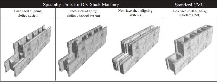
Specially designed units for dry-stack construction are available in many different configurations as shown in Figure 1. The latest and most sophisticated designs incorporate face shell alignment features that make units easier and faster to stack plumb and level. Other units are fabricated with a combination of keys, tabs or slots along both horizontal and vertical faces as shown in Figure 1 so that they may interlock easily when placed. Physical tolerances of dry-stack concrete units are limited to ±1/16 in. (1.58 mm.) which precludes the need for mortaring, grinding of face shell surfaces or shimming to even out courses during construction. Interlocking units placed in running bond resist flexural and shear stresses resulting from out-of-plane loads as a result of the keying action: (a) at the top of a web with the recess in the web of the unit above, (b) at two levels of bearing surface along each face shell at the bed joint, and (c) between adjacent blocks along the head joint. The first of these two interlocking mechanisms also ensures vertical alignment of blocks.
The interlocking features of dry-stack units improve alignment and leveling, reduce the need for skilled labor and reduce construction time. Floor and roof systems can be supported by mortarless walls with a bond beam at the top of the wall which expedites the construction process.
Wall strength and stability are greatly enhanced with grouting which provides the necessary integrity to resist forces applied parallel, and transverse to, the wall plane. Vertical alignment of webs ensures a continuous grout column even when the adjacent cell is left ungrouted. Grouting is necessary to develop flexural tensile stress normal to the bed joints, which is resisted through unit-mortar bond for traditional masonry construction. Strength of grouted dry-stack walls may also be enhanced by traditional reinforcement, prestressing, post-tensioning or with external fiber-reinforced surface coatings (surface bonding) as described in the next section.
Typical applications for mortarless concrete masonry include basement walls, foundation walls, retaining walls, exterior above-grade walls, internal bearing walls and partitions. Dry-stack masonry construction can prove to be a cost-effective solution for residential and low-rise commercial applications because of it’s speed and ease of construction, strength and stability even in zones of moderate and high seismicity. More information on design and construction of dry-stack masonry can be found in Reference 5.
Figure 1–– Dry-Stack Masonry Units
CONSTRUCTION
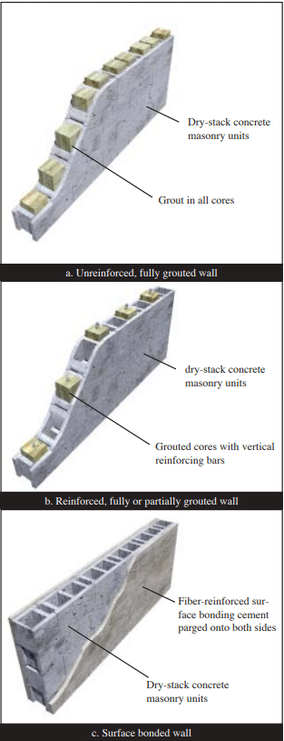
Dry-stack concrete masonry units can be used to construct walls that are grouted or partially grouted; unreinforced, reinforced or prestressed; or surface bonded. With each construction type, walls are built by first stacking concrete masonry units.
For unreinforced construction as shown in Figure 2a, grouting provides flexural and shear strength to a wall system. Flexural tensile stresses due to out-of-plane bending are resisted by the grout cores. Grout cores also interlace units placed in running bond and thus provide resistance to in-plane shear forces beyond that provided by friction developed along horizontal joints. Grout cores can also be reinforced to increase flexural strength.
Reinforcement can be placed vertically, in which case only those cells containing reinforcement may be grouted as shown in Figure 2b, as well as horizontally, in which case the masonry must be fully grouted. Another version is to place vertical prestressing tendons in place of reinforcement. Vertical axial compressive stress, applied via the tendons, increases flexural and shear capacity. Tendons may be bonded to grout, or unbonded, based upon the design. Placement of grout may be optional. Horizontally reinforced bond beam lintels can be created using a grout stop beneath the unit to contain grout.
As an alternative to reinforcing or prestressing, wall surfaces may be parged (coated) with a fiber-reinforced surface bonding cement/stucco per ASTM C887(ref. 14) as illustrated in Figure 2c. This surface treatment, applied to both faces of a wall, bonds concrete units together without the need for grout or internal reinforcement. The parging material bridges the units and fills the joints between units to provide additional bonding of the coating to the units through keying action. The compressive strength of the parging material should be equal to or greater than that of the masonry units.
Figure 2–– Basic Dry-Stack Masonry Wall Types
Laying of Units
The first course of dry-stack block should be placed on a smooth, level bearing surface of proper size and strength to ensure a plumb and stable wall. Minor roughness and variations in level can be corrected by setting the first course in mortar. Blocks should be laid in running bond such that cells will be aligned vertically.
Grout and Reinforcement
Grout and grouting procedures should be the same as used in conventional masonry construction (ref. 1, 10) except that the grout must have a compressive strength of at least 2600 psi (190 MPa) at 28 days when tested in accordance with ASTM C 1019 (ref.12). Placement of grout can be accomplished in one lift for single-story height walls less than 8 ft (2.43 m). Grout lifts must be consolidated with an internal vibrator with a head size less than 1 in. (25 mm).
Vertical Reinforcing
As for conventional reinforced masonry construction, good construction practice should include placement of reinforcing bars around door and window openings, at the ends, top and bottom of a wall, and between intersecting walls. Well detailed reinforcement such as this can help enhance nonlinear deformation capacity, or ductility, of masonry walls in building systems subjected to earthquake loadings – even for walls designed as unreinforced elements. Additional information on conventional grouting and reinforced masonry wall can be found in TEK 09-04A and TEK 03-03B (refs. 9 & 6).
Pre-stressed Walls
Mortarless walls can also be prestressed by placing vertical tendons through the cores. Tendons can be anchored within the concrete foundation at the base of a wall or in a bottom bond beam and are tensioned from the top of a wall.
Surface Bonded Walls
For walls strengthened with a surface bonding, a thin layer of portland cement surface bonding material should be troweled or sprayed on to a wall surface. The thickness of the surface coating should be at least ⅛ in. (3.2 mm.) or as required by the material supplier.
ENGINEERING PROPERTIES
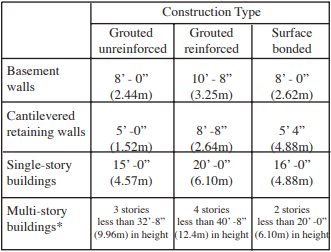
Walls constructed with mortarless masonry can be engineered using conventional engineering principles. Existing building code recommendations such as that produced by the building code (ref. 1) can serve as reference documents, but at the time of this printing it does not address mortarless masonry directly. It is thus considered an alternate engineered construction type. The International Building Code (ref. 7) does list allowable stresses based on gross-cross-sectional area for dry-stacked, surface-bonded concrete masonry walls. These values are the same as presented in TEK 03-05A (ref. 16). Suggested limits on wall or building height are given in Table 1.
Test data (refs. 2, 3 and 4) have shown that the strength of drystack walls exceeds the strength requirements of conventional masonry, and thus the recommended allowable stress design practices of the code can be used in most cases. When designing unreinforced, grouted masonry wall sections, it is important to deduct the thickness of the tension side face shell when determining the section properties for flexural resistance.
Table 1 –– Summary of Wall Heights for 8” (203 mm) Dry-stacked Units (ref. 5)
* Laterally supported at each floor
Unit and Masonry Compressive Strength
Units used for mortarless masonry construction are made of the same concrete mixes as used for conventional masonry units. Thus, compressive strength of typical units could vary between 2000 psi (13.79MPa) and 4000 psi. (27.58 MPa) Standard Methods of Sampling and Testing Concrete Masonry Units (ref. 11) can be referred to for determining strength of dry-stack units.
Masonry compressive strength f’m can conservatively be based on the unit-strength method of the building code (ref . 15), or be determined by testing prisms in accordance with ASTM C1314 (ref. 4). Test prisms can be either grouted or ungrouted depending on the type of wall construction specified.
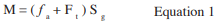
Because no mortar is used to resist flexural tension as for conventional masonry construction, flexural strength of mortarless masonry is developed through the grout, reinforcement or surface coating. For out-of-plane bending of solid grouted walls allowable flexural strength can be estimated based on flexural tensile strength of the grout per Equation 1.
Consideration should be given to the reduction in wall thickness at the bed joints when estimating geometrical properties of the net effective section.
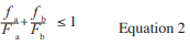
Correspondingly, flexural strength based on masonry compressive stress should be checked, particularly for walls resisting significant gravity loads, using the unity equation as given below.
Buckling should also be checked. (Ref. 8)
In-Plane Shear Strength
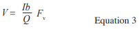
Shear strength for out-of-plane bending is usually not a concern since flexural strength governs design for this case. For resistance to horizontal forces applied parallel to the plane of a wall, Equation 3 may be used to estimate allowable shear strength.
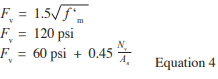
Fv is the allowable shear strength by the lesser of the three values given in Equation 4.
Grouted, Reinforced Construction
Mortarless masonry that is grouted and reinforced behaves much the same as for conventional reinforced and mortared construction. Because masonry tensile strength is neglected for mortared, reinforced construction, flexural mechanisms are essentially the same with or without the bed joints being mortared provided that the units subjected to compressive stress are in good contact. Thus, allowable stress design values can be determined using the same assumptions and requirements of the MSJC code. (ref.1)
Axial and flexural tensile stresses are assumed to be resisted entirely by the reinforcement. Strains in reinforcement and masonry compressive strains are assumed to vary linearly with their distance from the neutral axis. Stresses in reinforcement and masonry compressive stresses are assumed to vary linearly with strains. For purposes of estimating allowable flexural strengths, full bonding of reinforcement to grout are assumed such that strains in reinforcement are identical to those in the adjacent grout.
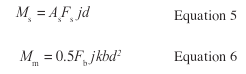
For out-of-plane loading where a single layer of vertical reinforcement is placed, allowable flexural strength can be estimated using the equations for conventional reinforcement with the lower value given by Equations 5 or 6.
In-Plane Shear Strength
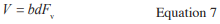
Though the MSJC code recognizes reinforced masonry shear walls with no shear, or horizontal reinforcement, it is recommended that mortarless walls be rein- forced with both vertical and horizontal bars. In such case, allowable shear strength can be determined based on shear reinforcement provisions (ref. 1) with Equations 7, 8 and 9.
Where Fv is the masonry allowable shear stress per Equations 8 or 9.
Solid Grouted, Prestressed Construction
Mortarless masonry walls that are grouted and pre- stressed can be designed as unreinforced walls with the prestressing force acting to increase the vertical compres- sive stress. Grout can be used to increase the effective area of the wall. Flexural strength will be increased because of the increase in the fa term in Equation 1. Shear strength will be increased by the Nv term in Equation 4.
Because the prestressing force is a sustained force, creep effects must be considered in the masonry. Research on the long-term behavior of dry-stacked masonry by Marzahn and Konig (ref. 8) has shown that creep effects may be accentuated for mortarless masonry as a result of stress concentrations at the contact points of adjacent courses. Due to the roughness of the unit surfaces, high stress concentrations can result which can lead to higher non-proportional creep deformations. Thus, the creep coefficient was found to be dependent on the degree of roughness along bed-joint surfaces and the level of applied stress. As a result, larger losses in prestressing force is probable for dry-stack masonry.
Surface-Bonded Construction
Dry-stack walls with surface bonding develop their strength through the tensile strength of small fiberglass fibers in the 1/8” (3.8mm) thick troweled or surface bonded cement-plaster coating ASTM C-887(Ref. 14). Because no grouting is necessary, flexural tension and shear strength are developed through tensile resistance of fiberglass fibers applied to both surfaces of a wall. Test data has shown that surface bonding can result in a net flexural tension strength on the order of 300 psi.(2.07 MPa) Flexural capacity, based on this value, exceeds that for conventional, unreinforced mortared masonry construction, therefore it is considered conservative to apply the desired values of the code (ref. 1) for allowable flexural capacity for portland cement / lime type M for the full thickness of the face shell.
Out-of-Plane and In-Plane Flexural Strength
Surface-bonded walls can be considered as unreinforced and ungrouted walls with a net allowable flexural tensile strength based on the strength of the fiber-reinforcement. Flexural strength is developed by the face shells bonded by the mesh. Allowable flexural strength can be determined using Equation 1 with an Ft value determined on the basis of tests provided by the surface bonding cement supplier. Axial and flexural compressive stresses must also be checked per Equation 2 considering again only the face shells to resist stress.
Surface Bonded In-Plane Shear Strength
In-plane shear strength of surface-bonded walls is attributable to friction developed along the bed joints resulting from vertical compressive stress in addition to the diagonal tension strength of the fiber coating. If the enhancement in shear strength given by the fiber reinforced surface parging is equal to or greater than that provided by the mortar-unit bond in conventional masonry construction, then allowable shear strength values per the MSJC code (ref. 1) may be used. In such case, section properties used in Equation 3 should be based on the cross-section of the face shells.
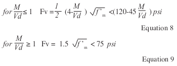
Figure 3 – A Mortarless Garden Wall Application
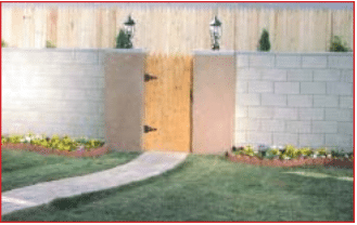
Figure 4 – A Residential, Mortarless, Single-Family Basement – Part of a 520 Home Development
REFERENCES
Building Code Requirements for Masonry Structures), ACI 530-02/ ASCE 5-02/TMS 402-02. Reported by the Masonry Standards Joint Committee (MSJC), 2002.
Drysdale, R.G., Properties of Dry-Stack Block, Windsor, Ontario, July 1999.
Drysdale, R.G., Properties of Surface-Bonded Dry-Stack Block Construction, Windsor, Ontario, January 2000.
Drysdale, R.G., Racking Tests of Dry-Stack Block, Windsor, Ontario, October 2000.
Drysdale, R.G., Design and Construction Guide for Azar Dry-Stack Block Construction, JNE Consulting, Ltd., February 2001.
Grout for Concrete Masonry, TEK 09-04A, Concrete Masonry & Hardscapes Association, 2002.
2000 International Building Code, Falls Church, VA. International Code Council, 2000.
Marzahn, G. and G. Konig, Experimental Investigation of Long-Term Behavior of Dry-Stacked Masonry, Journal of The Masonry Society, December 2002, pp. 9-21.
Hybrid Concrete Masonry Construction Details, TEK 0303B. Concrete Masonry & Hardscapes Association, 2009.
Specification for Masonry Structures, ACI 530.1-02/ASCE 6-02/ TMS 602-02. Reported by the Masonry Standards Joint Committee (MSJC), 2002.
Standard Methods of Sampling and Testing Concrete Masonry Units, ASTM C140-02a, ASTM International, Inc. , Philadelphia, 2002.
Standard Method of Sampling and Testing Grout, ASTM C1019-02, ASTM International, Inc., Philadelphia, 2002.
Standard Specification for Grout for Masonry, ASTM C 476-02. ASTM International, Inc., 2002
Standard Specification for Packaged, Dry, Combined Materials for Surface Bonding Mortar, ASTM C 887-79a (2001). ASTM International, Inc., 2001.
Standard Test Method for Compressive Strength of Masonry Assem blages, ASTM C1314-02a, ASTM International, Inc., Philadelphia, 2002.
An net cross-sectional area of masonry, in² (mm²) As effective cross-sectional area of reinforcement, in2 (mm2) b width of section, in. (mm) d distance from extreme compression fiber centroid of tension reinforcement, in. (mm) Fa allowable compressive stress due to axial load only, psi (MPa) Fb allowable compressive stress due to ß exure only, psi (MPa) Fs allowable tensile or compressive stress in reinforcement, psi (MPa) Ft flexural tensile strength of the grout, psi(MPa) Fv allowable shear stress in masonry psi (MPa) fa calculated vertical compressive stress due to axial load, psi (MPa) fb calculated compressive stress in masonry due to ß exure only, psi (MPa) f’ specified compressive strength of masonry, psi (MPa) I moment of inertia in.4 (mm4) j ratio of distance between centroid of flexural compressive forces and centroid of tensile forces to depth, d k ratio of the distance between compression face of the wall and neu tral axis to the effective depth d M maximum moment at the section under consideration, in.-lb (N-mm) Nv compressive force acting normal to the shear surface, lb (N) Q first moment about the neutral axis of a section of that portion of the cross section lying between the neutral axis and extreme fiber in.³ (mm³) Sg section modulus of uncracked net section in.³ (mm³) V shear force, lb (N)
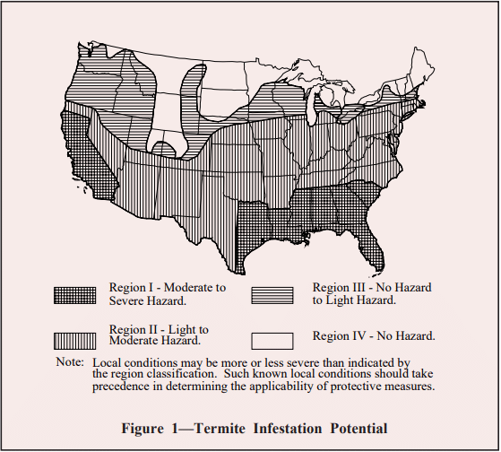
Termites are distributed widely throughout the United States, causing substantial damage to unprotected wood buildings. Although there are over forty species of termites in the United States alone (over 2,500 species around the world), most termite damage is attributed to subterranean termites. Recently, much attention and concern has been directed to the relative newcomer, the very aggressive Formosan termite, found mainly in the southern states and Hawaii, but is dramatically increasing in numbers and spreading toward the northern states. In Southern Louisiana the population is estimated to have increased more than 3,000% in the past ten years alone.
Concrete masonry is one of the best products available for termite resistance since it does not provide a source of nutrition. Entire structures can be constructed of concrete and masonry materials, virtually eliminating the possibility of damage from termites. This includes a composite block/steel bar joist floor system that is immune to termite attack (ref. 2).
This TEK focuses on measures to reduce the possibility of subterranean termite entry into a building. While termites do not cause any damage to masonry materials, they do feed on any products containing cellulose, most notably wood. Buildings that do not use wood or cellulose products as a construction material are not prone to termite infestation making concrete masonry the perfect application for both above and below grade construction. Concrete masonry is very versatile with an almost endless array of architectural shapes, sizes textures and colors available. When wood is used as a construction material, the further the food source is from the soil, the lower the likelihood of termite infestation such as the traditional wood roof framing.
Subterranean termites nest in the ground because they require a moist, humid environment to survive. Entry into a building must be gained through a sheltered path, such as a crack in a foundation wall or slab. If a sheltered path to the food source is not available, it is possible for termites to build their own access tunnels, which protect them from sunlight and open air. Often, these access tunnels can be the only direct sign of a termite infestation.
It is important to consider the potential for termite infestation during the construction phase since the building construction practices themselves can help protect against future infestation. Many of these measures focus on proper design and quality construction to reduce possible entry routes and to provide a hostile (that is, dry) environment to ward off termites. These same methods may already be employed for protection from water penetration or soil gas entry.
Strategies for termite control include:
building out of all concrete masonry;
minimizing cracks in walls and slabs;
sealing around all wall and floor penetrations;
adequate drainage around the foundation and adjacent soil;
providing access to inspect for termite tunnels;
installing barriers to prevent termite entry;
maintaining a minimum clearance between wood members and soil;
treating soil with chemicals to repel termites; and
utilizing termite resistant construction materials.
The level of termite control employed on a particular job should be consistent with the expected severity of the termite hazard. This level of severity for a particular location can be determined from local experience or from the state entomological authorities. Where such information is not available, Figure 1 may serve as a guide.
Figure 1—Termite Infestation Potential
SITE CONDITIONS
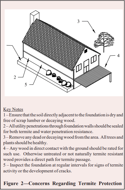
While preparing the site prior to construction, all roots, stumps, dead timber, and other wood debris should be removed from the site. Similarly, wood scraps from construction should be properly disposed. Leaving this material on site or in the backfill provides additional food sources for termites, attracting them and increasing the likelihood of infestation. Similarly, wood grade stakes or bracing stakes should be removed before or during a concrete placement and not be cast into the concrete. Leaving them in place attracts termites and provides a direct path for them through the concrete. Refer to Figure 2 for a summary of critical termite access areas.
Backfilling with a free draining soil, incorporating a subgrade drainage system, and installing proper above-grade water drainage will help keep the foundation and adjacent soil dry, providing a less hospitable environment for termites.
In extreme circumstances, subterranean termites may not require constant access to and from the adjacent soil. Where conditions exist such that wood remains continuously wet, termites do not need to return to the soil to obtain water. However, such conditions are rare if proper design and construction for water penetration resistance are adhered to.
Figure 2—Concerns Regarding Termite Protection
REDUCING ENTRY ROUTES
Once the termites have established a path, they have unimpeded access to the entire structure. Therefore, keeping termites out of the structure should always be the paramount objective. In addition to the obvious points of entry, such as wood in direct contact with the soil, other obscure (but critical) termite entry routes include:
through cracks in exposed wall faces or slabs. Termites are capable of moving through a crack only 1/32 inch (0.79 mm) wide;
direct access from soil under porches or patio slabs;
along the outside of pipes penetrating slabs or foundation walls; and
access tunnels on the interior or exterior of walls.
Minimum Clearance to Soil
It is desirable to keep wood elements as far as possible from the soil to minimize termite access. Nonstructural wood elements, such as wood siding and trim, should be kept a minimum of 6 inches (152 mm) from the soil surface. Structural wood framing, sill plates, and sheathing should be kept at least 8 inches (203 mm) above the soil, or as otherwise required by local building codes. However, if the nonstructural wood is in contact with the structural wood (which is generally the case), the 6 inch (152 mm) minimum clearance should be increased to 8 inches (203 mm). These general clearances do not apply to pressure-treated wood or other termite and decay resistant woods.
Minimizing Cracks
Proper structural design of foundation walls, footings, and slabs will help prevent structural cracking that may allow termite entry. In addition to preventing cracks due to structural overload, cracking due to concrete shrinkage also needs to be addressed. Due to fluctuations in the temperature and moisture content, all materials have a tendency to expand and contract over time. With concrete masonry foundations, the primary concern focuses on shrinkage resulting in the development of tensile stresses. This is because the tensile strength of concrete is relatively small compared to the compressive strength; therefore shrinkage may result in small cracks within the masonry.
It is normally not necessary to provide control joints in below grade residential concrete masonry basement walls. A control joint is a planned joint in a concrete masonry wall at regular intervals that accommodates shrinkage movement without unsightly, random cracking. The lack of a need for control joints is attributed to the relatively low range of thermal and moisture fluctuations occurring in below grade walls afforded by the soil adjacent to the walls and to the water resistant systems applied to basement walls. In most below grade basement wall construction, it is possible to provide a reinforced bond beam at or near the top of the wall in lieu of control joints to minimize crack development. The bond beam also provides a cap, preventing termites from coming up through the empty cores of ungrouted block and gaining entry into the building. Joint reinforcement embedded in the horizontal bed joints, usually at 16 inches on center, also provides additional tensile strength for the masonry and aids in crack control. It should be pointed out that horizontal reinforcement will not completely eliminate cracking, but it will hold the cracks so tightly together that the termites cannot get through.
Additional measures to reduce the shrinkage cracking potential of concrete masonry include keeping the walls dry during construction. Because drying shrinkage is a primary cause of cracking in concrete masonry walls, it is important to minimize the potential for wetting concrete masonry during the construction process. At the jobsite, concrete block should be stored so as to protect the units from absorbing ground water or precipitation. This includes storing block on pallets (or otherwise isolating block from direct contact with the ground) and covering the units with plastic or other water-repellent materials.
Concrete masonry units should be dry when laid. Some surface moisture is acceptable; however, saturated units should be allowed to dry out before placement in the wall. Concrete masonry units should never be wetted before or during placement in the wall, as may be customary with other types of masonry units.
At the end of each workday, a weatherproof membrane should be placed over uncompleted walls to protect the units from rain or snow. Placing a board on top of the membrane will help hold it in place and will prevent the membrane from sagging into the masonry cores and allowing water to collect. To limit concrete slab cracking, the recommendations of the American Concrete Institute (ref. 5) for quality concrete placement should be followed.
In basement walls, the dampproofing and waterproofing measures employed to reduce water penetration aid in the prevention of termite entry. Waterproofing and dampproofing systems require that the barrier be continuous to prevent water penetration into voids or open seams. Similarly, the barrier is typically carried above the finished grade level to prevent water entry between the barrier and the foundation wall. Cracks exceeding 0.02 inches (0.5 mm) should be repaired before applying a waterproof or damp-proof barrier. However, the repair of hairline cracks is typically not required, as most barriers will either fill or span these small openings. In addition, waterproofing and dampproofing systems should be applied to clean dry walls. In all cases, manufacturer’s directions should be carefully followed for proper installation.
Particular attention should be paid to reentrant corners at garages, porches, and fireplaces and to wall penetrations. Because stress concentrations develop at these intersections, pliable membranes and/or additional reinforcement are often recommended at these locations to span any poten- tial cracks or hold them tightly together.
Typical water penetration measures include coatings, sheet membranes, and drainage boards. Coatings are sprayed, trowelled, or brushed onto below-grade walls, providing a continuous barrier to water entry. Coatings should be applied to clean, structurally sound walls. Walls should be brushed or washed to remove dirt, oil, efflorescence, or other materials that may reduce the bond between the coating and the wall.
Sheet membranes and panels (drainage boards) are less dependent on workmanship and on surface preparation than coatings. Many of the membrane systems are better able to remain intact in the event of settlement or other movement of the foundation wall. All seams, terminations, and penetrations must be properly sealed. Care must also be exercised during the backfilling process to ensure that the barrier is not damaged.
In crawl space and stem walls, which typically are not treated on the exterior to prevent water entry as basement walls are, crack control measures become more important. In these cases, termites can enter the block through small cracks and move unseen up ungrouted cores. In these instances, solid grouting or capping of the walls is recommended.
Capping Concrete Masonry Walls
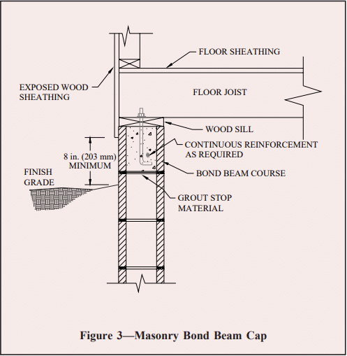
Various methods are used to seal the tops of masonry foundation walls. Should termites penetrate the face shell of a concrete masonry wall below, the cap prevents them from direct access to the wood superstructure. In reinforced construction, the masonry bond beam at the top of the wall serves as an effective cap, as shown in Figure 3.
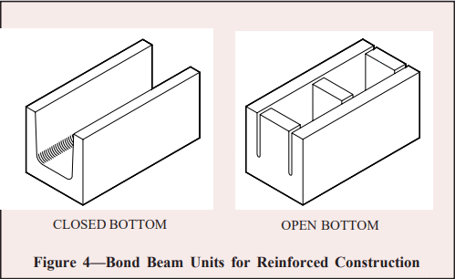
Bond beam units are specifically designed to accommodate horizontal reinforcement and grout as shown in Figure 4. Bond beam units can be either solid bottom or open bottom. The latter requires a screen grout stop or expanded metal to contain the grout within the unit. A reinforced bond beam is preferred to solid units or solid bottom units with solid head joints since the reinforcement in bond beams will hold any cracks that form tightly together to prevent termite entry through the cracks.
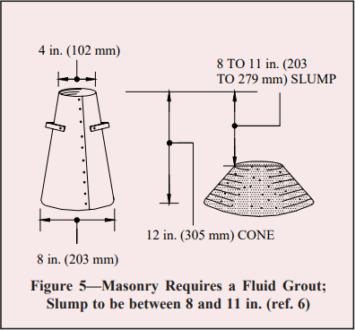
Proper grouting procedures are important to ensure bond with the masonry units and void free areas in bond beams and cells to be filled. Grout should conform to the Specification for Grout for Masonry, ASTM C476 (ref. 7) or be specified to have a minimum compressive strength of 2,000 psi (13.8 MPa) at 28 days in accordance with the Specification for Masonry Structures, ACI 530.1/ASCE 6/TMS 402 (ref. 6). The Specification also requires enough water in the grout mixture to achieve a slump of 8 to 11 inches (203 to 279 mm) (ref. 6, 4) when tested in accordance with ASTM C143 Standard Test Method for Slump of Hydraulic Cement Concrete (ref. 9). See Figure 5.
This high slump is contrary to the principles of cast-in-place concrete where high slump levels lead to reduced strengths and higher shrinkage. Many engineers mistakenly try to apply this same analogy to masonry – lowering the water content in an effort to reduce shrinkage potential. However, in masonry construction, the high slump is critical as it allows the grout to be fluid enough to flow around reinforcement and completely fill all the voids (ref. 3, 4, and 6). The initial high water-to-cement ratio is reduced significantly as the masonry units absorb the excess water, resulting in higher strengths and low shrinkage properties despite the high initial water-to-cement ratio. Additionally, as the excess water is absorbed into the masonry units, some of the cement is drawn into the unit with the water creating excellent bond and reducing the formation of voids.
Grout should also be placed in lifts not exceeding 5 ft. (ref. 6). A lift is the layer of grout placed in a single continuous operation. Additionally, each lift should be consolidated with either a ¾ in. (19 mm) diameter low velocity vibrator. Consolidation eliminates voids, helping to ensure complete grout fill and good bond with the masonry units. After the water is absorbed from the grout mixture into the masonry (normally 3 to 10 minutes after placement, depending on the absorption characteristics of the unit and weather conditions), the grout should be reconsolidated to close the space left by the excess water that was absorbed (ref. 3). In any case, reconsolidation must be completed before the grout loses its plasticity.
Metal termite shields may be installed as a continuous barrier directly below the sill plate. If infestation occurs, termites are forced to build conspicuous access tunnels around the shield, making detection easy. Because termites require only a 1/32 inch (0.79 mm) gap for penetration, termite shields must be installed with great care to be effective. All seams must be soldered and all openings around anchor bolts and service lead-ins must be sealed. Because of the extreme care required to provide an impenetrable metal termite shield, they generally are not to be relied on for termite protection.
Figure 3—Masonry Bond Beam Cap
Figure 4—Bond Beam Units for Reinforced Construction
Figure 5—Masonry Requires a Fluid Grout; Slump to be between 8 and 11 in. (ref. 6)
Exterior Insulation
The rigid plastic foams that are often used to insulate crawl space and the exterior side of basement walls can allow termites to create undetectable tunnels and is prohibited for such use by some codes (ref. 7). An advantage of concrete masonry foundation walls is their ability to accommodate insulation within the cores of the masonry units where it is protected from direct contact with the soil. Either rigid foam insulation inserts, granular fill insulation, or foamedin-place insulation can be used for this purpose.
Additional Considerations for Crawl Spaces
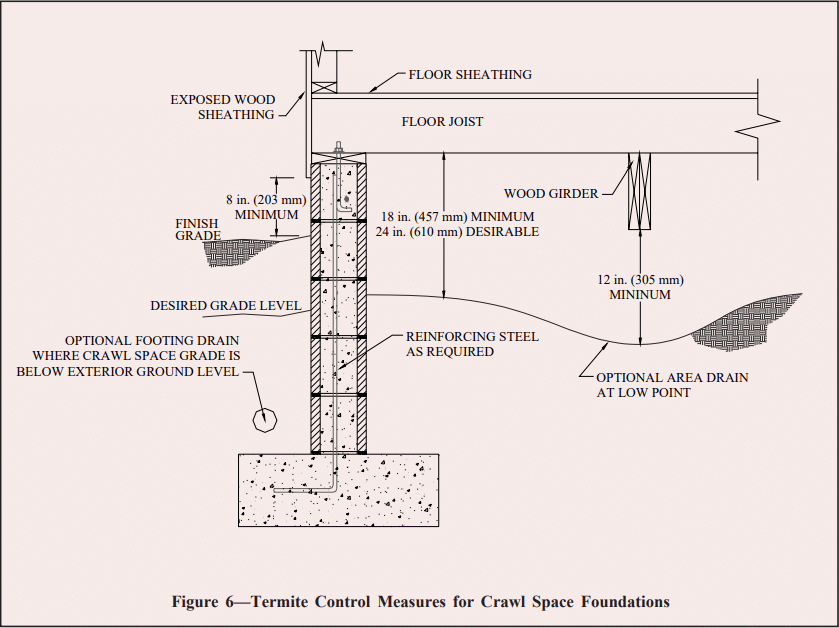
Figure 6 illustrates termite control measures for crawl space foundations. Crawl space floors should be kept at or above the exterior finished grade to facilitate drainage in the crawl space. Where this is not possible, or on sites where water flows toward the building due to the site slope, area drains should be installed. Unless specified otherwise by local codes, wood girders should be at least 12 inches (305 mm) above the crawl space floor, and wood joists should be no closer than 18 inches (457 mm) to the soil. In all cases, enough clearance should be maintained to allow access to the crawl space for inspection.
Figure 6—Termite Control Measures for Crawl Space Foundations
CHEMICAL TREATMENTS
Numerous methods are available to create a pesticide barrier within the soil adjacent to a structure to prevent termite entry. Soil treatment before or during construction is often most effective as there is better access to the subgrade soil. If a slab-on-grade is also going to be used, the soil under the slab can also be pretreated. While post-construction treatment is far more common, it is also more difficult. Limited access to some areas may not allow for an effective chemical barrier to be established.
CONCLUSION
Concrete masonry is an ideal construction material to resist termites. It does not provide food to attract them, and provides a barrier to prevent termite entry. It is also very versatile with an almost endless amount of architectural shapes, sizes, textures, and colors available. An innovative, totally termite proof concrete masonry floor system utilizing a hidden steel bar joist supporting system is also available.
REFERENCES
Basement Manual: Design and Construction Using Concrete Masonry, CMU-MAN-002-01, Concrete Masonry & Hardscapes Association, 2001.
Concrete Masonry Homes: Recommended Practices. U.S. Department of Housing and Urban Development, Office of Policy Development and Research, 1999.