Resources

Foam Plastic Insulation in Concrete Masonry Walls

INTRODUCTION

Foam plastic insulation is often used in exterior concrete masonry construction to improve steady state thermal performance (R-values), and in some cases to improve air and moisture infiltration properties as well. Because of their potential flammability and smoke generation in case of fire, the International Building Code (IBC) (ref. 1) imposes additional requirements on these materials when they are used in exterior walls. These requirements are covered in IBC section 2603.

Foam plastic insulations include both rigid board (expanded polystyrene, extruded polystyrene, polyisocyanurate) as well as open cell and closed-cell spray-applied or foamed-in-place insulations. They may be used on the interior, exterior or in the cores (as either inserts or foamed-in-place) of single wythe masonry walls, and in the cavities of masonry cavity walls.

Because these plastics are flammable, the IBC mandates that they be protected by fire-resistance-rated materials or assemblies in wall and roof assemblies, to prevent the plastic insulation from contributing to the spread of fire in a building.

This TEK describes the IBC requirements for assemblies containing foam plastic insulation and presents details of concrete masonry walls that comply with those requirements. Note that this TEK focuses on the requirements for masonry wall assemblies: there may be additional requirements for the insulation, such as flame spread index and labeling.

IBC REQUIREMENTS

IBC Section 2603 regulates the use of foam plastic insulation in all types of construction, both combustible and noncombustible, with the intent of limiting the spread of fire via these materials. For exterior walls, Section 2603 requires:

  • a thermal barrier between foam plastic insulation and the building interior, which can be satisfied with a 1 in. (25 mm) minimum thickness of concrete or masonry,
  • ignition testing for foam plastic insulations applied to wall exteriors, although assemblies protected with at least 1 in. (25 mm) of concrete or masonry on the exterior are exempt from testing, and
  • successful testing in accordance with NFPA 285, Standard Fire Test Method for Evaluation of Fire Propagation Characteristics of Exterior Non-Load-Bearing Wall Assemblies Containing Combustible Components (ref. 2).

Note that there are two important exceptions to the requirement for NFPA 285 testing:

  1. Wall assemblies where the foam plastic insulation is covered on each face by a minimum 1 in. (25 mm) thickness of masonry or concrete and meeting one of the following:
    a) there is no air space between the insulation and the concrete or masonry (as occurs with foamed-in-place insulation); or
    b) the insulation has a flame spread index of 25 or less as determined by ASTM E84, Standard Test Method for Surface Burning Characteristics of Building Materials, or UL 723, Standard for Test for Surface Burning Characteristics of Building Materials, (refs. 3, 4) and the air space between the insulation and the concrete or masonry does not exceed 1 in. (25 mm).
  2. One-story buildings meeting the following conditions: foam plastic with a flame spread index of 25 or less and a smoke-developed index of 450 max can be placed in exterior walls without a thermal barrier where it is covered with aluminum (at least 0.032 in. (0.813 mm) thick) or corrosion-resistant steel (at least 0.0160 in. (0.406 mm) thick), provided that the insulation is not thicker than 4 in. (102 mm), and that the building is equipped with an automatic sprinkler system.

Wall assemblies meeting the requirements listed under number 1 above and buildings meeting the requirements listed under number 2 are deemed to comply with the Section 2603 requirements. Note that in cases where there is less than 1 in. (25 mm) of masonry over the insulation, there are insulations available that will meet the NFPA 285 requirements.

NFPA 285 REQUIREMENTS

NFPA 285 addresses the possibility of fire entering wall cavities through door or window openings, igniting foam plastic insulation and spreading vertically to upper stories.

The test evaluates exterior wall assemblies for buildings required to have exterior walls of noncombustible construction. The test provides a method of determining the flammability characteristics of exterior nonloadbearing wall assemblies. It is intended to evaluate combustible components included within wall assemblies required to be noncombustible, under conditions of a fire originating in the building interior.

NFPA 285 evaluates four conditions:

  • flame propagation over the exterior face;
  • flame propagation within combustible components from one story to the next;
  • vertical flame propagation on the interior wall surface from one story to the next; and
  • lateral flame propagation from one compartment to the next.

To evaluate these conditions, a two-story wall assembly with a window opening on the first floor is constructed in the test assembly. After a 30-minute fire exposure with the burner in the window opening, recorded temperatures are compared to the Standard’s conditions of acceptance to determine compliance. Note that the test evaluates wall assemblies, not specific materials.

SINGLE WYTHE CONCRETE MASONRY WALLS

Single wythe walls may incorporate foam insulation in the cores of the masonry units as either rigid foam inserts or foamed in-place insulation. As discussed above, IBC Chapter 26 essentially requires a minimum of 1 in. (25 mm) of concrete or masonry on the interior and exterior of the foam insulation, as well as protection at headers to prevent ignition of the insulation above door and window openings.

When placed in concrete masonry cores, the foam plastic insulation is protected on the interior and exterior by the concrete face shells. Minimum face shell thickness for concrete masonry units is governed by ASTM C90, Standard Specification for Loadbearing Concrete Masonry Units, (ref. 5) as listed in Table 1. Table 1 shows that concrete masonry units of 6-in. (152 mm) thickness or greater provide the IBC-required 1 in. (25 mm) interior and exterior protection. Because of the small core size of 4-in. (102-mm) units, the cores of these units are rarely insulated. When insulation is placed in the cells of concrete masonry units and bond beams are provided at each story and lintels over each opening, the insulation is fully encapsulated. This meets the intent of the code to prevent the propagation of fire within wall cavities and no further isolation is necessary in this case.

In single wythe construction, door and window headers are typically constructed using either a reinforced precast lintel or a reinforced concrete masonry lintel (shown in Figure 1). This detail provides concrete cover well over the 1 in. (25 mm) minimum required by Section 2603. The detail and level of protection would be similar with a precast concrete lintel. Refer to TEK 19-02B, Design for Dry Single Wythe Concrete Masonry Walls (ref. 6), for additional details on flashing single wythe walls.

MULTI-WYTHE WALLS

Multi-wythe concrete masonry construction is most commonly masonry cavity walls, which often incorporate foam plastic insulation in the cavity formed by the two masonry wythes. In this case, there is more than 1 in. (25 mm) of masonry on both the interior and exterior, so the focus for protecting the insulation is on the headers and jambs of window and door openings.

Per Building Code Requirements for Masonry Structures (ref. 8) concrete masonry veneer walls are to have a minimum specified 1 in. (25 mm) air space with special precautions to limit mortar overhangs inside the cavity to allow adequate drainage between the wythes. Exception b to NFPA 285 testing (see page 1) limits the air space between the insulation and the masonry to 1 in. (25 mm) maximum. Therefore, when exception b is being used, the designer should specify a 1 in. (25 mm) air space to meet both requirements.

Figure 3 shows a window top of opening detail in a concrete masonry cavity wall. In this case, 1 in. (25 mm) of mortar is slushed into the cavity below the insulation to provide the required level of protection. In addition, testing (refs. 7, 10) has shown that mineral wool fire safing covering insulation board exposed at openings in a masonry cavity wall is sufficient to pass NFPA 285 requirements. Note that mineral wool insulation cannot be exposed to the moisture in the drainage cavity. If used, it must be behind flashing or similarly protected.

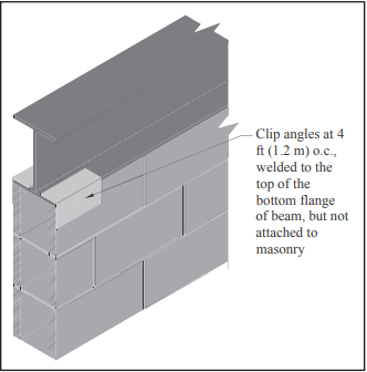
The jambs of metal doors (see Figure 4) are typically filled with mortar as the wall is constructed, again providing adequate protection for the insulation.

For wood door jambs, several options are shown in Figures 5 and 6. Figure 5 shows a detail where the insulation is held 1 in. (25 mm) back from the jamb. An additional piece of insulation bridges the cavity and acts as a backer for a 1 in (25 mm) layer of mortar. Another option is shown in Figure 6, where the unit adjacent to the jamb is turned 90o, and the unit is cut so that part of the face shell extends across the cavity, between the jamb and the insulation. On the alternate courses, a piece of the cut face shell can be mortared across the cavity to provide the protection. Wood window jamb details are very similar, as shown in Figures 7 and 8.

REFERENCES

  1. International Building Code. International Code Council, 2015.
  2. Standard Fire Test Method for Evaluation of Fire Propagation Characteristics of Exterior Non-Load-Bearing Wall Assemblies Containing Combustible Components, NFPA 285. National Fire Protection Association, 2012.
  3. Standard Test Method for Surface Burning Characteristics of Building Materials, ASTM E84-13a. ASTM International, 2013.
  4. Standard for Test for Surface Burning Characteristics of Building Materials, UL 723. Underwriter’s Laboratories, 2008.
  5. Standard Specification for Loadbearing Concrete Masonry Units, ASTM C90-13. ASTM International, 2013.
  6. Design for Dry Single-Wythe Concrete Masonry Walls, TEK 19 02B. Concrete Masonry & Hardscapes Association, 2012.
  7. NFPA 285-[06] Approved Wall Assemblies Using Foam Plastic Insulation From Dow, Tech Solutions 514.0. Dow Chemical Company, 2009.
  8. Building Code Requirements for Masonry Structures, TMS 402 11/ACI 530-11/ASCE 5-11. Reported by the Masonry Standards Joint Committee, 2011.
  9. Standard Test Method for Determining Ignitability of Exterior Wall Assemblies Using a Radiant Heat Energy Source, NFPA 268. National Fire Protection Association, 2012.
  10. Commercial Complete™ Wall System NFPA 285 Tested Wall Assemblies. Owens Corning Insulating Systems, LLC, 2012.

Design of Concrete Masonry Infill

INTRODUCTION

Masonry infill refers to masonry used to fill the opening in a structural frame, known as the bounding frame. The bounding frame of steel or reinforced concrete is comprised of the columns and upper and lower beams or slabs that surround the masonry infill and provide structural support. When properly designed, masonry infills provide an additional strong, ductile system for resisting lateral loads, in-plane and out-of-plane.

Concrete masonry infills can be designed and detailed to be part of the lateral force-resisting system (participating infills) or they can be designed and detailed to be structurally isolated from the lateral force-resisting system and resist only out-of-plane loads (non-participating infills).

Participating infills form a composite structural system with the bounding frame, increasing the strength and stiffness of the wall system and its resistance to earthquake and wind loads.

Non-participating infills are detailed with structural gaps between the infill and the bounding frame to prevent the unintended transfer of in-plane loads from the frame into the infill. Such gaps are later sealed for other code requirements such as weather protection, air infiltration, energy conservations, etc.

Construction of concrete masonry infilled frames is relatively simple. First, the bounding frame is constructed of either reinforced concrete or structural steel, then the masonry infill is constructed in the portal space. This construction sequence allows the roof or floor to be constructed prior to the masonry being laid, allowing for rapid construction of subsequent stories or application of roofing material.

The 2011 edition of Building Code Requirements for Masonry Structures (MSJC Code, ref. 1) includes a new mandatory language Appendix B for the design of masonry infills that can be either unreinforced or reinforced. Appendix B provides a straightforward method for the design and analysis of both participating and non-participating infills. Requirements were developed based on experimental research as well as field performance.

MASONRY INFILL LOAD RESPONSE

Several stages of in-plane loading response occur with a participating masonry infill system. Initially, the system acts as a monolithic cantilever wall whereby slight stress concentrations occur at the four corners, while the middle of the panel develops an approximately pure shear stress state. As loading continues, separation occurs at the interface of the masonry and the frame members at the off-diagonal corners. Once a gap is formed, the stresses at the tensile corners are relieved while those near the compressive corners are increased.

As loading continues, further separation between the masonry panel and the frame occurs, resulting in contact only near the loaded corners of the frame. This results in the composite system behaving as a braced frame, which leads to the concept of replacing the masonry infill with an equivalent diagonal strut, as shown in Figure 1. These conditions are addressed in the masonry standard.

Participating masonry infills resist out-of-plane loads by an arching mechanism. As out-of-plane loads increase beyond the elastic limit, flexural cracking occurs in the masonry panel. This cracking (similar to that which occurs in reinforced masonry) allows for arching action to resist the applied loads, provided the infill is constructed tight to the bounding frame and the infill is not too slender.

IN-PLANE SHEAR FOR PARTICIPATING INFILLS

For participating infills, the masonry is either mortared tight to the bounding frame so that the infill receives lateral loads immediately as the frame displaces, or the masonry is built with a gap such that the bounding frame deflects slightly before it bears upon the infill. If a gap exists between the infill and the frame, the infill is considered participating if the gap is less than in. (9.5 mm) and the calculated displacements, according to MSJC Code Section B3.1.2.1. However, the infill can still be designed as a participating infill, provided the calculated strength and stiffness are reduced by half.

The maximum height-to-thickness ratio (h/t) of the participating infill is limited to 30 in order to maintain stability. The maximum thickness allowed is one-eighth of the infill height.

The MSJC Code requires participating infills to fully infill the bounding frame and have no openings—partial infills or infills with openings may not be considered as part of the lateral force resisting system because structures with partial infills have typically not performed well during seismic events. The partial infill attracts additional load to the column due to its increased stiffness; typically, this results in shear failure of the column.

The in-plane design is based on a braced frame model, with the masonry infill serving as an equivalent strut. The width of the strut is determined from Equation 1 (see Figure 1).

where:

The term λstrut, developed by Stafford Smith and Carter (ref. 2) in the late 60s, is the characteristic stiffness parameter for the infill and provides a measure of the relative stiffness of the frame and the infill. Design forces in the equivalent strut are then calculated based on elastic shortening of the compression-only strut within the braced frame. The area of the strut used for that analysis is determined by multiplying the strut width from Equation 1 by the specified thickness of the infill.

The infill capacity can be limited by shear cracking, compression failure, and flexural cracking. Shear cracking can be characterized by cracking along the mortar joints (which includes st epped and horizontal cracks) and by diagonal tensile cracking. The compression failure mode consists of either crushing of the masonry in the loaded diagonal corners or failure of the equivalent diagonal strut. The diagonal strut is developed within the panel as a result of diagonal tensile cracking. Flexural cracking failure is rare because separation at the masonry-frame interface usually occurs first; then, the lateral force is resisted by the diagonal strut.

As discussed above, the nominal shear capacity is determined as the least of: the capacity infill corner crushing; the horizontal component of the force in the equivalent strut at a racking displacement of 1 in. (25 mm); or, the smallest nominal shear strength from MSJC Code Section 3.2.4, calculated along a bed joint. The displacement limit was found to be a better predictor of infill performance than a drift limit.

Generally, the infill strength is reached at lower displacements for stiff bounding columns, while more flexible columns result in the strength being controlled at the 1-in. (25-mm) displacement limit. While MSJC Code Section 3.2 is for unreinforced masonry, use of equations from that section does not necessarily imply that the infill material must be unreinforced. The equations used in MSJC Code Section 3.2 are more clearly related to failure along a bed joint and are therefore more appropriate than equations from MSJC Code Section 3.3 for reinforced masonry.

The equations used in the code are the result of comparing numerous analytical methods to experimental results. They are strength based. The experimental results used for comparison were a mixture of steel and reinforced concrete bounding frames with clay and concrete masonry. While some methods presented by various researchers are quite complex, the code equations are relatively simple.

OUT-OF-PLANE FLEXURE FOR PARTICIPATING INFILLS

The out-of-plane design of participating infills is based on arching of the infill within the frame. As out-of-plane forces are applied to the surface of the infill, a two-way arch develops, provided that the infill is constructed tight to the bounding frame. The code equation models this two-way arching action.

As previously mentioned, the maximum thickness allowed for calculation for the out-of-plane capacity is one-eighth of the infill height. Gaps between the bounding frame on either the sides or top of the infill reduce the arching mechanism to a one-way arch and are considered by the code equations. Bounding frame members that have different cross sectional properties are accounted for by averaging their properties for use in the code equations.

NON-PARTICIPATING INFILLS

Because non-participating infills support only out-of-plane loads, they must be detailed to prevent in-plane load transfer into the infill. For this reason, MSJC Code Section B.2.1 requires these infills to have isolation joints at the sides and the top of the infill. These isolation joints must be at least in. (9.5 mm) and sized to accommodate the expected design displacements of the bounding frame, including inelastic deformation due to a seismic event, to prevent the infill from receiving in-plane loadings. The isolation joints may contain filler material as long as the compressibility of the material is taken into consideration when sizing the joint.

Mechanical connectors and the design of the infill itself ensure that non-participating infills support out-of-plane loads. Connectors are not allowed to transmit in-plane loads. The masonry infill may be designed to span vertically, horizontally, or both. The masonry design of the non-participating infill is carried out based on the applicable MSJC Code sections for reinforced or unreinforced masonry (Section 3.2 for unreinforced infill and Section 3.3 for reinforced infill using strength design methods). Note that there are seismic conditions which may require the use of reinforced masonry.

Because they support only out-of-plane loads, non-participating infills can be constructed with full panels, partial height panels, or panels with openings. The corresponding effects on the bounding frame must be included in the design.

BOUNDING FRAME FOR PARTICIPATING INFILLS

The MSJC Code provides guidance on the design loads applied to the bounding frame members; however, the actual member design is governed by the appropriate material code and is beyond the scope of the MSJC Code.

The presence of infill within the bounding frame places localized forces at the intersection of the frame members. MSJC Code Section B.3.5 helps the designer determine the appropriate augmented loads for designing the bounding frame members. Frame members in bays adjacent to an infill, but not in contact with the infill, should be designed for no less than the forces (shear, moment, and axial) from the equivalent strut frame analysis. In the event of infill failure, the loading requirement on adjacent frame members ensures adequacy in the frame design, thus preventing progressive collapse.

The shear and moment applied to the bounding column must be at least the results from the equivalent strut frame analysis multiplied by a factor of 1.1. The axial loads are not to be less than the results of that analysis. Additionally, the horizontal component of the force in the equivalent strut is added to the design shear for the bounding column.

Similarly, the shear and moment applied to the bounding beam or slab must be at least the results from the equivalent strut frame analysis multiplied by a factor of 1.1, and the axial loads are not to be less than the results of that analysis. The vertical component of the force in the equivalent strut is added to the design shear for the bounding beam or slab.

The bounding frame design should also take into consideration the volumetric changes in the masonry infill material that may occur over time due to normal temperature and moisture variations. Shrinkage of concrete masonry infill material may open gaps between the infill and the bounding frame that need to be addressed. Guidance for these volumetric changes is provided in MSJC Code Section 1.7.5.

CONNECTORS

Mechanical connectors between the bounding frame and the infill provide out-of-plane support of the masonry, for both participating and non-participating infills. Connectors are required only for the direction of span (i.e., at the top and bottom of the infill for infill spanning vertically, for example). The connectors must be designed to support the expected out-of-plane loads and may not be spaced more than 4 ft (1.2 m) apart along the perimeter of the infill. Figure 2 shows an example of a mechanical connector composed of clip angles welded to the bottom flange of the steel beam.

Connectors for both participating and non-participating infills are not permitted to transfer in-plane loads from the bounding frame to the infill. For participating infills, in-plane loads are assumed to be resisted by a diagonal compression strut (see Figure 1), which does not rely upon mechanical connectors to transfer in-plane load. Research (ref. 3) has shown that when connectors transmit in-plane loads they create regions of localized stress and can cause premature damage to the infill. This damage then reduces the infill’s out-of-plane capacity because arching action is inhibited.

EXAMPLE 1: DESIGN OF PARTICIPATING MASONRY INFILL WALL FOR IN-PLANE LOADS

Consider the simple structure of Figure 3. The east and west side walls are concrete masonry infills laid in running bond, while the north and south walls are store-fronts typical of convenience stores. Steel frames support all gravity loads and the lateral load in the east-west direction. The bounding columns are W10x45s oriented with the strong axis in the east-west direction. The bounding beams above the masonry infill are W10x39s. The masonry infill resists the lateral load in the north-south direction.

Use nominal 8-in. (203-mm) concrete masonry units, f’m = 1,500 psi (10.34 MPa), and Type S PCL mortar. Assume hollow units with face-shell bedding only. The total wall height measures 16 ft-10 in. (5.1 m) to the roof with the infill being 16 2 ft (4.9 m). The building is loaded with a wind load of 24 lb/ft² calculated per ASCE 7-10 (ref. 6) in the north-south direction. The roof acts as a one-way system, transmitting gravity loads to the north and south roof beams. Infill and bounding beam properties are summarized in Tables 1 and 2.

MSJC Code Section B.3.4.3 requires Vn inf to be the smallest of the following:

  • (6.0 in.)tnet inf f’m
  • the calculated horizontal component of the force in the equivalent strut at a horizontal racking displacement of 1.0 in. (25 mm)
  • Vn/1.5, where Vn is the smallest nominal shear strength from MSJC Code Section 3.2.4, calculated along a bed joint.

MSJC Code Section 3.2.4 requires the nominal shear strength not exceed the least of the following:

  • 3.8 Anf ′m
  • 300An
  • 56An + 0.45Nv for running bond masonry not fully grouted and for masonry not laid in running bond, constructed of open end units, and fully grouted
  • 90An + 0.45Nv for running bond masonry fully grouted
  • 23An for masonry not laid in running bond, constructed of other than open end units, and fully grouted

As a result of the wind loading, the reaction transmitted to the roof diaphragm is:

Reaction = ½ (24lb/ft²)(16.83 ft)
= 202 lb/ft (2.95 kN/m)

Total roof reaction acting on one side of the roof is
Reaction = (202 lb/ft)(30 ft)
= 6,060 lb (27.0 kN)

This reaction is divided evenly between the two masonry infills, so the shear per infill is 3,030 lb (13.5 kN).

Using the conservative loading case of 0.9D + 1.0W,
Vu = 1.0 Vunfactored = 1.0 (3,030 lb) = 3,030 lb (13.5 kN)

To be conservative, the axial load to the masonry infill is taken as zero.

To ensure practical conditions for stability, the ratio of the nominal vertical dimension to the nominal thickness is limited to 30 for participating infills. The ratio for this infill is:
h/t = 192 in./8 in. = 24 < 30
The ratio is less than 30 and the infill is therefore acceptable as a participating infill.

The width of the equivalent strut is calculated by Equation 1 (MSJC Code Equation B-1):

where λstrut is given by Equation 2 (Code Equation B-2).

The angle of the equivalent diagonal strut, θstrut, is the angle of the infill diagonal with respect to the horizontal.
θstrut = tan-1 (hinf/linf) = tan-1 (192 in./360 in.) = 28.1°

Using Equation 2, the characteristic stiffness parameter, λstrut, for this infill is then:

The resulting strut width is then:

The stiffness of the equivalent braced frame is determined by a simple braced frame analysis where the stiffness is based on the elastic shortening of the diagonal strut. The strut area is taken as the width of the strut multiplied by the net thickness of the infill.

The stiffness is:

where d is the diagonal length of the infill, 34 ft (10.3 m) in this case.

The nominal shear capacity, Vn, is then the least of:

The design shear capacity is:

The design shear capacity far exceeds the factored design shear of 3,030 lb (13.5 kN), so the infill is satisfactory for shear.

Additionally, the provisions of MSJC Code Section B.3.5 require that the designer consider the effects of the infill on the bounding frame. To ensure adequacy of the frame members and connections, the shear and moment results of the equivalent strut frame analysis are multiplied by a factor of 1.1. The column designs must include the horizontal component of the equivalent strut force, while the beam designs must include the verti cal component of the equivalent strut force. The axial forces from the equivalent strut frame analysis must also be considered in both the column and beam designs.

EXAMPLE 2: DESIGN OF PARTICIPATING MASONRY INFILL WALL FOR OUT-OF-PLANE LOADS

Design the infill from the previous example for an out-of-plane wind load W of 24 lb/ft² (1.2 kPa) per ASCE 7-10 acting on the east wall, using Type S PCL mortar, and units with a nominal thickness of 8 in. (203 mm). Assume hollow units with face-shell bedding only and that the infill is constructed tight to the bounding frame such that there are no gaps at the top or sides of the infill. See Table 3 for frame properties.

MSJC Code Section B.3.6 provides the equations for the nominal out-of-plane flexural capacity. MSJC Code Equation B-5 requires that the flexural capacity of the infill be:

Using the conservative loading case of 0.9D + 1.0W, the design wind load pressure is:

q = 1.0W = 1.0 x 24 psf = 24 psf (1.15 kPa)
tinf = 7.625 in. < (⅛)(192 in.), OK

The design flexural capacity exceeds the factored design wind load pressure of 24 lb/ft² (1.2 kPa), so the infill is satisfactory for out-of-plane loading

NOTATIONS

An            = net cross-sectional area of a member, in.² (mm²)
D              = dead load, psf (Pa)
d               = diagonal length of the infill, in. (mm)
Ebb           = modulus of elasticity of bounding beams, psi (MPa)
Ebc            = modulus of elasticity of bounding columns, psi (MPa)
Em             = modulus of elasticity of masonry in compression, psi (MPa)
f’m             = specified compressive strength of masonry, psi (MPa)
h                = effective height of the infill, in. (mm)
hinf             = vertical dimension of infill, in. (mm)
Ibb              = moment of inertia of bounding beam for bending in the plane of the infill, in.4 (mm4)
Ibc               = moment of inertia of bounding column for bending in the plane of the infill, in.4 (mm4)
linf               = plan length of infill, in. (mm)
Nv                = compressive force acting normal to shear surface, lb (N)
qn inf            = nominal out-of-plane flexural capacity of infill per unit area, psf (Pa)
t                    = nominal thickness of infill, in. (mm)
tinf                = specified thickness of infill, in. (mm)
tnet inf           = net thickness of infill, in. (mm)
Vn                 = nominal shear strength, lb (N)
Vn inf             = nominal horizontal in-plane shear strength of infill, lb (N)
Vu                  = factored shear force, lb (N)
Vunfactored    = unfactored shear force, lb (N)
W                  = out of plane wind load, psf (Pa)
winf               = width of equivalent strut, in. (mm)
αarch              = horizontal arching parameter for infill, lb0.25 (N0.25)
βarch              = vertical arching parameter for infill, lb0.25 (N0.25)
λstrut              = characteristic stiffness parameter for infill, in.-1 (mm-1)
θstrut              = angle of infill diagonal with respect to the horizontal, degrees
ϕ                     = strength reduction factor

REFERENCES

  1. Building Code Requirements for Masonry Structures, TMS 402-11/ACI 530-11/ASCE 5-11. Reported by the Masonry Standards Joint Committee, 2011.
  2. Stafford-Smith, B. and Carter, C. (1969) “A Method for the Analysis of Infilled Frames.” Proceedings of the Institution of Civil Engineers, 44, 31-48.
  3. Dawe, J. L., and Seah, C. K. (1989a). “Behavior of Masonry Infilled Steel Frames.” Canadian Journal of Civil Engineering, Ottowa, 16, 865-876.
  4. Tucker, Charles J. “Infilling the Frame With Masonry.” Structure, May 2012.
  5. Tucker, Charles J. “Changing Masonry Standards: Masonry Infills.” Structure, Feb. 2012.
  6. Minimum Design Loads for Buildings and Other Structures, ASCE SEI 7-10. American Society of Civil Engineers Structural Engineering Institute, 2010.


Empirical Design of Concrete Masonry Walls

INTRODUCTION

Empirical design is a procedure of proportioning and sizing unreinforced masonry elements based on known historical performance for a given application. Empirical provisions preceded the development of engineered masonry design, and can be traced back several centuries. This approach to design is based on historical experience in lieu of analytical methods. It has proven to be an expedient design method for typical loadbearing structures subjected to relatively small wind loads and located in areas of low seismic risk. Empirical design has also been used extensively for the design of exterior curtain walls and interior partitions.

Using empirical design, vertical and lateral load resistance is governed by prescriptive criteria which include wall height to thickness ratios, shear wall length and spacing, minimum wall thickness, maximum building height, and other criteria, which have proven to be effective through years of experience.

This TEK is based on the provisions of Section 2109 of the International Building Code (IBC) (ref. 1). These empirical design requirements do not apply to other design methods such as allowable stress or limit states design. For empirical design of foundation walls, see TEK 15-01B, Allowable Stress Design of Concrete Masonry Foundation Walls (ref. 2)

APPLICABILITY OF EMPIRICAL DESIGN

The IBC allows elements of masonry structures to be designed by empirical methods when assigned to Seismic Design Category (SDC) A, B or C, subject to additional restrictions described below. When empirically designed elements are part of the seismic lateral force resisting system, however, their use is limited to SDC A.

Empirical design has primarily been used with masonry laid in running bond. When laid in stack bond, the IBC requires a minimum amount of horizontal reinforcement (0.003 times the wall’s vertical cross-sectional area and spaced not more than 48 in. (1,219 mm) apart).

In addition, buildings that rely on empirically designed masonry walls for lateral load resistance are allowed up to 35 ft (10.7 m) in height.

The 2003 IBC restricts empirical design to locations where the basic wind speed (three-second gust, not fastest mile) is less than or equal to 110 mph (79 m/s), as defined in Minimum Design Loads for Buildings and Other Structures, ASCE 7 (ref. 3). A wind speed of this velocity generally applies along the East and Gulf coasts of the United States.

The 2006 IBC further refines the empirical design limitations. Whereas with the 2003 IBC, the designer need only check the SDC and basic wind speed, with the 2006 IBC, to use empirical design the designer must check:

  • SDC,
  • basic wind speed,
  • building height, and
  • location of gravity loads resultant.

The limitations based on SDC are the same as in the 2003 IBC, described above. Building height and basic wind speed conditions where empirical design is permitted under the 2006 IBC are summarized in Table 1.

The 2006 IBC also requires the resultant of gravity loads to fall within the kern of the masonry element, to avoid imparting tension to the element. This area is defined as: within the center third of the wall thickness, or, for foundation piers, within the central area bounded by lines at one-third of each cross-sectional dimension of the pier.

DESIGN PROVISIONS

Minimum Wall Thickness

Empirically designed (unreinforced) bearing walls of one story buildings must be at least 6 in. (152 mm) thick. For buildings more than one story high, walls must be at least 8 in. (203 mm) thick. The minimum thickness for unreinforced masonry shear walls and for masonry foundation walls is also 8 in. (203 mm). Note that the 2003 IBC allows shear walls of one-story buildings to have a minimum thickness of 6 in. (152 mm).

Lateral Support

Lateral support for walls can be provided in the horizontal direction by cross walls, pilasters, buttresses and structural frame members, or in the vertical direction by floor diaphragms, roof diaphragms and structural frame members, as illustrated in Figure 1. For empirically designed walls, such support must be provided at the maximum intervals given in Tables 2 and 3. Note that the span limitations apply to only one direction; that is, the span in one direction may be unlimited as long as the span in the other direction meets the requirements of Tables 2 or 3.

Allowable Stresses

Allowable stresses in empirically designed masonry due to building code prescribed vertical (gravity) dead and live loads (excluding wind or seismic) are given in Table 4.

Table 4 includes two sets of compressive stresses for hollow concrete masonry units (CMU). The first set, titled “Hollow Unit Masonry (Units Complying With ASTM C 90- 06 or Later)” apply to most CMU currently available. The 2006 edition of the CMU specification, Standard Specification for Loadbearing Concrete Masonry Units, ASTM C 90 (ref. 7), included slightly reduced minimum face shell thickness requirements for CMU 10 in. (254 mm) and greater in width. These smaller face shells require a corresponding adjustment to the allowable compressive stresses. The values currently published in the 2006 IBC (“Hollow Unit Masonry (Units Complying With Previous Editions of ASTM C 90)” in Table 4), apply to the previous face shell thicknesses, and should only be used if the CMU to be used have the thicker face shells listed in previous editions of ASTM C 90. This distinction is not applicable to masonry that will be solidly grouted.

Calculated compressive stresses for both single and multiwythe walls are determined by dividing the design load by the gross cross-sectional area of the wall, excluding areas of openings, chases or recesses. The area is based on the specified dimensions of masonry, rather than on nominal dimensions. In multiwythe walls, the allowable stress is determined by the weakest combination of units and mortar shown in Table 4.

In addition, the commentary to Building Code Requirements for Masonry Structures (refs. 6, 8) contains additional guidance for concentrated loads. According to the commentary, when concentrated loads act on empirically designed masonry, the course immediately under the point of bearing should be a solid unit or be filled solid with mortar or grout. Further, when the concentrated load acts on the full wall thickness, the allowable stresses under the load may be increased by 25 percent. The allowable stresses may be increased by 50 percent when concentrated loads act on concentrically placed bearing plates that are greater than one-half but less than the full area.

Anchorage for Lateral Support

Where empirically designed masonry walls depend on cross walls, roof diaphragms, floor diaphragms or structural frames for lateral support, it is essential that the walls be properly anchored so that the imposed loads can be transmitted from the wall to the supporting element. Minimum anchorage requirements for intersecting walls and for floor and roof diaphragms are shown in Figures 2 and 3, respectively.

Masonry walls are required to be anchored to structural frames that provide lateral support by ½ in. (13 mm) diameter bolts spaced at a maximum of 4 ft (1.2 m), or with other bolts and spacings that provide equivalent anchorage. The bolts must be embedded a minimum of 4 in. (102 mm) into the masonry.

In addition, the 2006 IBC requires the designer to check the roof loading for net uplift and, where net uplift occurs, to design the anchorage system to entirely resist the uplift.

Shear Walls

Where the structure depends on masonry walls for lateral stability against wind or earthquake forces, shear walls must be provided parallel to the direction of the lateral forces as well as in a perpendicular plane, for stability.

Requirements for empirically designed masonry shear walls are shown in Figure 4.

Shear wall spacing is determined empirically by the length-to-width aspect ratio of the diaphragms that transfer lateral forces to the shear walls, as listed in Table 5. In addition, roofs must be designed and constructed in a manner such that they will not impose thrust perpendicular to the shear walls to which they are attached.

The height of empirically designed shear walls is not permitted to exceed 35 ft (10.7 m). The minimum nominal thickness of shear walls is 8 in. (203 mm), except under the 2003 IBC, which allows shear walls of one-story buildings to have a minimum thickness of 6 in. (152 mm).

Bonding of Multiwythe Walls

Wythes of multiwythe masonry walls are required to be bonded together. Bonding can be achieved using masonry headers, metal wall ties, or prefabricated joint reinforcement, as illustrated in Figure 5. Various empirical requirements for each of these bonding methods are given below.

Bonding of solid unit walls with masonry headers.
Where masonry headers are used to bond wythes of solid masonry construction, at least 4 percent of the wall surface of each face must be composed of headers, which must extend at least 3 in. (76 mm) into the backing. The distance between adjacent full-length headers may not exceed 24 in. (610 mm) in either the horizontal or vertical direction. In walls where a single header does not extend through the wall, headers from opposite sides must overlap at least 3 in. (76 mm), or headers from opposite sides must be covered with another header course which overlaps the header below by at least 3 in. (76 mm).

Bonding of hollow unit walls with masonry headers.
Where two or more hollow units are used to make up the thickness of a wall, the stretcher courses must be bonded at vertical intervals not exceeding 34 in. (864 mm) by lapping at least 3 in. (76 mm) over the unit below, or by lapping at vertical intervals not exceeding 17 in. (432 mm) with units that are at least 50 percent greater in thickness than the units below.

Bonding with metal wall ties (other than adjustable ties).
Wire size W2.8 (MW18) wall ties, or metal wire of equivalent stiffness, may be used to bond wythes. Each 4½ ft² (0.42 m²) of wall surface must have at least one tie. Ties must be spaced a maximum of 24 in. (610 mm) vertically and 36 in. (914 mm) horizontally. Hollow masonry walls must use rectangular wall ties for bonding. In other walls, ends of ties must be bent to 90° angles to provide hooks no less than 2 in. (51 mm) long. Additional bonding ties are required at all openings, and must be spaced a maximum of 3 ft (914 mm) apart around the perimeter and located within 12 in. (305 mm) of the opening. Note that wall ties may not include drips, and that corrugated ties may not be used.

Bonding with adjustable ties.
Adjustable ties must be spaced such that there is one tie for each 1.77 ft² (0.164 m²) of wall area, with maximum horizontal and vertical spacings of 16 in. (406 mm). The ties must have a maximum clearance between connecting parts of 1/16 in. (1.6 mm), and, when pintle legs are used, at least two legs with a minimum wire size of W2.8 (MW18). The bed joints of the two wythes may have a maximum vertical offset of no more than 1¼ in. (32 mm). (See Reference 9 for an illustration of these requirements.)

Bonding with prefabricated joint reinforcement.
Where adjacent wythes of masonry are bonded with prefabricated joint reinforcement, there must be at least one cross wire serving as a tie for each 2 ft² (0.25 m²) of wall area. The joint reinforcement must be spaced 24 in. (610 mm) or closer vertically. Cross wires on prefabricated joint reinforcement must be at least wire size W1.7 (MW11) and shall be without drips. The longitudinal wires must be embedded in the mortar.

Change in Wall Thickness

Whenever wall thickness is decreased, at least one course of solid masonry, or special units or other construction, must be placed under the thinner section to ensure load transfer to the thicker section below.

Miscellaneous Empirical Requirements

Following are additional empirical requirements in Building Code Requirements for Masonry Structures. Although not included explicitly in IBC Section 2109, the IBC includes a direct reference to Building Code Requirements for Masonry Structures.

Chases and Recesses
Masonry directly above chases or recesses wider than 12 in. (305 mm) must be supported on lintels.

Lintels
Lintels are designed as reinforced beams, using either the allowable stress design or the strength design provisions of Building Code Requirements for Masonry Structures. End bearing must be at least 4 in. (102 mm), although 8 in. (203 mm) is typical.

Support on Wood
Empirically designed masonry is not permitted to be supported by wood girders or other forms of wood construction, due to expected deformations in wood from deflection and moisture, causing distress in the masonry, and due to potential safety implications in the event of fire.

Corbelling
When corbels are not designed using allowable stress design or strength design, they may be detailed using the empirical requirements shown in Figure 6. Only solid or solidly grouted masonry units may be used for corbelling.

EMPIRICALLY DESIGNED PARTITION WALLS

In many cases, the building structure is designed using traditional engineered methods, such as strength design or allowable stress design, but the interior nonloadbearing masonry walls are empirically designed. In these cases, the partition walls are supported according to the provisions listed in Tables 2 and 3, but it is important that the support conditions provide isolation between the partition walls and the building’s structural elements to prevent the building loads from being transferred into the partition. The anchor, or other support, must provide the required lateral support for the partition wall while also allowing for differential movement. This is in contrast to the “Anchorage for Lateral Support” section, which details anchorage requirements to help ensure adequate load transfer between the building structure and the loadbearing masonry wall.

Figure 7 shows an example of such a support, using clip angles. C channels or adjustable anchors could be used as well. The gap at the top of the wall should be between ½ and 1 in. (13 and 25 mm), or as required to accommodate the anticipated deflection. The gap is filled with compressible filler, mineral wool or a fire-rated material, if required. Fire walls may also require a sealant to be applied at the bottom of the clip angles. This joint should not be filled with mortar, as it may allow load transfer between the structure and the partition wall.

REFERENCES

  1. International Building Code. International Code Council, 2003 and 2006.
  2. Allowable Stress Design of Concrete Masonry Foundation Walls, TEK 15-01B. Concrete Masonry & Hardscapes Association, 2001.
  3. Minimum Design Loads for Buildings and Other Structures, ASCE 7-02. New York, NY: American Society of Civil Engineers, 2002.
  4. Minimum Design Loads for Buildings and Other Structures, ASCE 7-05. New York, NY: American Society of Civil Engineers, 2005.
  5. Masonry Designer’s Guide, 5th Edition. Council for Masonry Research and The Masonry Society, 2007.
  6. Building Code Requirements for Masonry Structures, ACI 530-08/ASCE 5-08/TMS 402-08. Reported by the Masonry Standards Joint Committee, 2008.
  7. Standard Specification for Loadbearing Concrete Masonry Units, ASTM C 90-06. ASTM International, Inc., 2006.
  8. Building Code Requirements for Masonry Structures, ACI 530/ASCE 5/TMS 402. Reported by the Masonry Standards Joint Committee, 2002 and 2005.
  9. Anchors and Ties for Masonry, TEK 12-01B. Concrete Masonry & Hardscapes Association, 2008.
  10. Floor and Roof Connections to Concrete Masonry Walls, TEK 05-07A. Concrete Masonry & Hardscapes Association, 2001.


Splices, Development & Standard Hooks for Concrete Masonry Based on the 2009 & 2012 IBC

INTRODUCTION

Building codes include requirements for minimum reinforcement development lengths and splice lengths, as well as requirements for standard hooks, to ensure the adequate transfer of stresses between the reinforcement and the masonry. This TEK presents these requirements, based on the provisions of both the 2012 and 2009 editions of the International Building Code (IBC) (refs. 1, 2). Masonry design in these codes is primarily based on Building Code Requirements for Masonry Structures (MSJC) (refs. 3, 4). Differences between the MSJC and IBC are noted in the text when they occur.

There are two main differences between the 2008 and 2011 editions of the MSJC that impact reinforcement development and splice lengths in the corresponding 2009 and 2012 editions of the IBC:

  1. under 2011 MSJC allowable stress design, the allowable tensile stress, Fs, of Grade 60 steel was increased from 24,000 psi (166 MPa) to 32,000 psi (221 MPa), and
  2. the 2011 MSJC includes new lap splice length provisions for when confinement reinforcement is used at lap splices.

TEK 12-04D (ref. 5) includes basic material requirements, corrosion protection and placement tolerances for reinforcement used in concrete masonry construction. In addition, prestressing steel is discussed in Post-Tensioned Concrete Masonry Wall Construction, TEK 03-14 (ref. 6).

SPLICES AND DEVELOPMENT LENGTH

Minimum development lengths are necessary to adequately transfer stresses between reinforcement and the grout or mortar in which it is embedded. Splicing of reinforcement serves a similar purpose: to adequately transfer stresses from one reinforcing bar to another.

Reinforcement can be developed by embedment length, hook, or mechanical anchoring device. The development of the reinforcing bars relies on mechanical interlock of the bar deformations, hook, and/or anchor along with sufficient masonry cover to prevent splitting of the masonry. Reinforcing bars may be spliced by lapping the reinforcement, by proprietary mechanical splices or by welding.

The required length of lap or development is determined according to the design procedure used (allowable stress design or strength design). In addition, these detailing requirements have been frequently revised in recent years. As a result, the minimum lap and development lengths can vary considerably from one code to the next as well as from one design method to another.

The following sections present the requirements for both the 2009 IBC and 2012 IBC for both allowable stress and strength design.

2009 IBC SPLICE & DEVELOPMENT REQUIREMENTS

2009 IBC Allowable Stress Design

Development Length & Lap Splicing

While the 2008 MSJC includes an equation to determine development and lap splice lengths, the 2009 IBC modifies the MSJC lap splice length. In accordance with the 2009 IBC, the minimum required lap length for spliced reinforcing bars is determined using Equation 1 (see Table 1).

Further, in regions of flexure where the design tensile stresses in the reinforcement, fs, exceed 80% of the allowable steel tensile stress, Fs, the IBC requires that the required length of lap determined by Equation 1 must be increased by 50%. Alternatively, equivalent means of stress transfer to accomplish the same 50% increase is permitted. Where epoxy coated bars are used, lap length is also required to be increased by 50% but does not apply to the 12 in. (305 mm) minimum.

Development length requirements for allowable stress design are determined in accordance with Equation 3 except that there is no maximum length limit of 72db.

When noncontact lap splices are used, the bars must be spaced no farther apart than one-fifth the required length of lap nor more than 8 in. (203 mm).

When using the allowable stress design method, development of wires in tension is determined using Equation 2 (see Table 2). The development length of epoxy-coated wires is increased 50% above the value determined using Equation 2 but does not apply to the 6 in. (152 mm) minimum.

Alternatives to Lap Splicing

Reinforcing bars can also be spliced by welding, mechanical splicing and in some cases end-bearing splicing. Reinforcing bars larger than No. 9 (M#29) are required to be spliced using mechanical connectors.

Welded splices require the bars to be butted or shortly lapped and welded to develop in tension at least 125% of the specified yield strength of the bar. All welding is required to conform to AWS D1.4 (ref. 7), and steel for welded splices must conform to ASTM A706 (ref. 8). In practice, however, welding tends to be an expensive splicing option.

Mechanical splicing of reinforcement typically employs proprietary couplers specifically designed for this application. Mechanical splices are required to have the bars connected to develop in tension or compression, as required, at least 125% of the specified yield strength of the bar.

Reinforcing bars can also be spliced using end-bearing splices, but only in members containing closed ties, closed stirrups or spirals for bars subject to compression only. End-bearing splices rely on the transmission of compressive stress by bearing of square-cut ends held in concentric contact by a suitable device. The bar ends are required to terminate in flat surfaces within 11/2 degrees of a right angle to the axis of the bars and be fitted within 3 degrees of full bearing after assembly. 

2009 IBC Strength Design

Development Length & Lap Splice Length

For development and lap splice length requirements, the 2009 IBC references the 2008 MSJC (see Equation 3 and Table 3), but adds a maximum length limit of 72db.

For Equation 3, the reinforcement size factor, g, is taken equal to 1.0 for No. 3 through No. 5 (M#10–M#16) reinforcing bars; 1.3 for No. 6 and No. 7 (M#19, M#22) bars; and 1.5 for No. 8 and No. 9 (M#25, M#29) bars. When epoxy coated bars are used, the development length determined by Equation 3 is required to be increased by 50%.

Bars spliced by noncontact lap splices must be spaced no farther apart than one-fifth the required length of lap and no more than 8 in. (203 mm).

Alternatives to Lap Splicing

Mechanical splices are required to have the bars connected to develop at least 125% of the specified yield strength of the bar in tension or compression, as required.

The IBC further stipulates that mechanical splices be classified as Type 1 or 2 according to Section 21.2.6.1 of ACI 318, Building Code Requirements for Structural Concrete and Commentary (ref. 10). Type 1 splices may not be used within the plastic hinge zone nor within a beam-column joint of intermediate or special reinforced masonry shear walls or special moment frames. Type 2 are permitted at any location.

A Type 2 splice is defined as a full mechanical splice that develops in tension or compression, as required, at least 1.25fy of the bar. This requirement is intended to avoid a splice failure when the reinforcement is subjected to expected stress levels in yielding regions. Type 1 splices are not required to satisfy the more stringent requirements for Type 2 splices, and so their use is limited as noted above.

Welded splices must have the bars butted and welded to develop at least 125% of the bar’s specified yield strength in tension or compression, as required. Welded splices must use ASTM A706 (ref. 9) steel reinforcement. Welded splices are not permitted to be used in plastic hinge zones of intermediate or special reinforced walls nor in special moment frames of masonry.

2012 IBC SPLICE & DEVELOPMENT REQUIREMENTS

Regarding development and splice lengths, two significant changes were incorporated into the 2011 MSJC, which are included by reference in the 2012 IBC:

  1. in the 2011 MSJC, the allowable tensile stress, Fs, of Grade 60 steel when using allowable stress design was increased from 24,000 psi (166 MPa) to 32,000 psi (221 MPa), and
  2. the 2011 MSJC includes new provisions for confinement reinforcement, for both allowable stress and strength design methods.

2012 IBC Allowable Stress Design

Equation 1 is still applicable for use in the 2012 IBC but with the increase in F the splice lengths of fully stressed bars will increase by 33%. Significant reductions of splice lengths in low stress areas are achieved, however. The minimums of 12 in. (305 mm) or 40db whichever is greater still apply as well.

The 2012 IBC allows the MSJC development length equation (Equation 3) to be used as an alternate to the IBC equation (Equation 1). When using Equation 3 under the 2012 IBC, however, the value of K is defined as the least of the masonry cover, 9db (vs. 5db in the 2009 IBC) and the clear spacing between adjacent reinforcement.

Tabulated values are presented in Tables 4a through 4d. Note, however, that there is no maximum length limit of 72db for allowable stress design.

Tables 4a and 4b present minimum lap splice lengths for reinforcement placed in the center of the wall, for f’m = 1,500 and 2,000 psi (10.3 and 13.7 MPa), respectively.

Tables 4c and 4d present minimum lap splice lengths for reinforcement offset in the wall, for f’m = 1,500 and 2,000 psi (10.3 and 13.7 MPa), respectively.

Other requirements for lap, mechanical, welded and end-bearing splices are identical to those under the 2009 IBC, with the exception of the new provisions for confinement reinforcement, presented below.

2012 IBC Strength Design

Requirements for development length as well as lap, mechanical and welded splices are identical to those for allowable stress design, and are presented in Tables 4a through 4d.

2012 IBC Lap Splices With Confinement Reinforcement

The 2012 IBC, by reference to the 2011 MSJC, includes new lap splice criteria where confinement reinforcement is placed. The criteria are the same for both allowable stress design and strength design.

The confinement reinforcement criteria allow a reduced lap splice length when reinforcement is provided transverse to lapped bars. Research has found that the transverse, or confinement, reinforcement increases the lap performance significantly, as long as there is at least one No. 3 (M#10) or larger transverse bar placed within the last 8 in. (203 mm) of each end of the lap (see Figure 1). Because of this effect, calculated lap splice lengths are permitted to be reduced by a confinement factor, ξ, determined using Equation 4:

where

db is the bar diameter of the vertical reinforcement

The reduced lap splice length is not permitted to be less than 36db. The clear space between the transverse bars and the lapped bars may not exceed 1.5 in. (38 mm), and the transverse bars must be fully developed in grouted masonry at the point where they cross the lapped reinforcement (see Figure 1). These provisions are included in Tables 4a through 4d

STANDARD HOOKS

Figure 2 illustrates the requirements for standard hooks, when reinforcing bars are anchored by hooks or by a combination of hooks and development length. These requirements apply to both the 2009 and 2012 IBC, for both allowable stress and strength design. Table 5 lists minimum dimensions and equivalent embedment lengths for standard hooks of various sizes. A combination of hook and development length must be used when the equivalent embedment length of the hook, le, is less than the required minimum development length, ld. In this case, development length equal to (ldle) must be provided in addition to the hook. This additional development length is measured from the start of the hook (point of tangency with the main portion of the bar).

JOINT REINFORCEMENT SPLICES

Joint reinforcement must have a minimum splice length of 6 in. (152 mm) to transfer shrinkage stresses. Slippage of the deformed side wires is resisted by surface bond as well as by mechanical anchorage of the embedded portions of the cross wires.

NOTATIONS:

Asc = area of the transverse bars at each end of the lap splice, in.² (mm²)
Di = min. inside diameter of bend for standard hooks, in. (mm)
db = nominal diameter of reinforcement, in. (mm)
K = the least of the masonry cover, 9db for the 2012 IBC (5db for the 2009 IBC) and the clear spacing between adjacent reinforcement, in. (mm)
Fs = allowable tensile stress in reinforcement, psi (MPa)
f’m = specified compressive strength of masonry, psi (MPa)
fs = calculated tensile or compressive stress in steel, psi (MPa)
fy = specified yield strength of steel, psi (MPa)
ld = embedment length or lap splice length of straight reinforcement, in. (mm)
le = equivalent embedment length provided by standard hooks measured from the start of the hook (point of tangency), in. (mm)
lt = length of bar extension of hooked confinement reinforcement, in. (mm)
γ = reinforcement size factor
ξ = lap splice confinement reinforcement factor

REFERENCES

  1. International Building Code 2012. International Code Council, 2012.
  2. International Building Code 2009. International Code Council, 2009.
  3. Building Code Requirements for Masonry Structures, TMS 402-11 /ACI 530-11/ASCE 5-11. Reported by the Masonry Standards Joint Committee, 2011.
  4. Building Code Requirements for Masonry Structures, TMS 402-08 /ACI 530-08/ASCE 5-08. Reported by the Masonry Standards Joint Committee, 2008.
  5. Steel Reinforcement for Concrete Masonry, TEK 12-04D. Concrete Masonry & Hardscapes Association, 2007.
  6. Post-Tensioned Concrete Masonry Wall Construction, TEK 03-14. Concrete Masonry & Hardscapes Association, 2002.
  7. Structural Welding Code—Reinforcing Steel, AWS D 1.4-05. American Welding Society, 2005.
  8. Standard Specification for Low-Alloy Steel Deformed and Plain Bars for Concrete Reinforcement, ASTM A706/A706M-09b. ASTM International, Inc., 2009.
  9. Building Code Requirements for Structural Concrete and Commentary, ACI 318-11. American Concrete Institute, 2011.

TEK 12-06A, Revised 2013. CMHA and the companies disseminating this technical information disclaim any and all responsibility and liability for the accuracy and the application of the information contained in this publication.