Concrete masonry offers many textures, colors and sizes, along with choices in bond patterns and joint treatment making it an excellent choice for exterior and interior walls in residential, commercial and public buildings. Concrete brick can be used in both structural and veneer applications and is economical, durable, easy to maintain, fire resistant, and reduces sound transmission.
Multi-wythe masonry walls are classified as either composite or noncomposite depending on how the wythes interact. Connections between wythes of composite walls are designed to transfer stresses between the wythes, allowing the wythes to act as a single member in resisting loads. In contrast, for noncomposite or cavity walls each wythe individually resists the loads imposed on it. Concrete brick are used both in composite walls and as nonloadbearing veneer in cavity wall construction. Requirements for concrete brick veneers are summarized in Concrete Masonry Veneers, TEK 03-06C (ref. 1).
Standard Specification for Concrete Building Brick, ASTM C 55 (ref. 2), governs concrete brick and similar solid units. C 55 requirements are summarized in Concrete Masonry Unit Shapes, Sizes, Properties, and Specifications, CMUTEC-001-23 (ref. 3).
STRUCTURAL DESIGN METHODS
Composite wall structural design requirements are contained in Building Code Requirements for Masonry Structures (ref. 4) and the International Building Code (ref. 5).
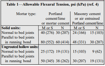
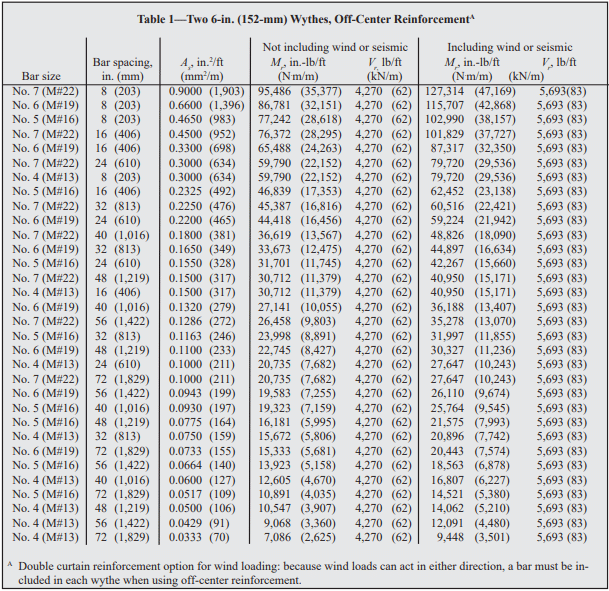
Allowable stress design of unreinforced composite walls is typically governed by the flexural tensile capacity of the masonry system (see Table 1), although compression and shear must also be checked. Shear stress in the plane of interface between wythes and collar joints is limited to 5 psi (34.5 kPa) for mortared collar joints; 10 psi (68.9 kPa) for grouted collar joints; and the square root of the unit compressive strength of the header (over the net area of the header) for headers.
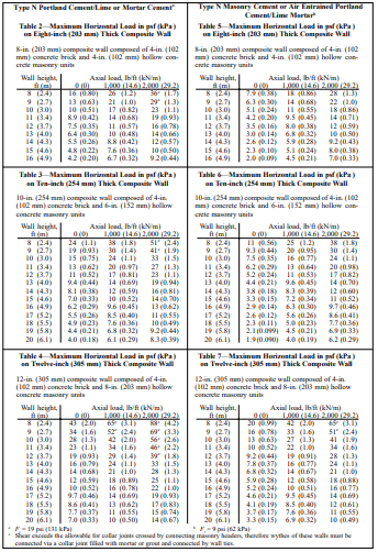
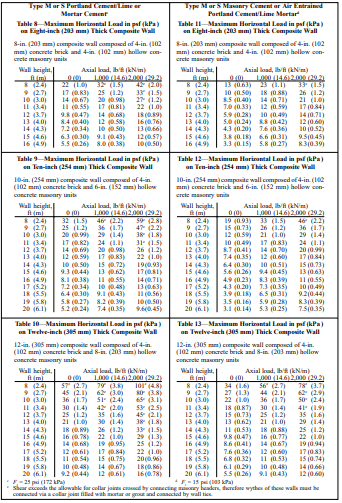
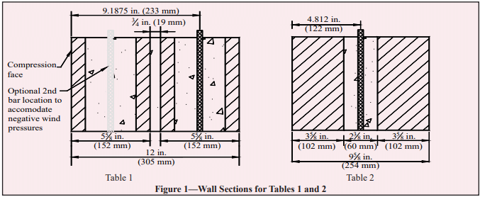
Tables 2 through 13, for lateral loads with or without concentric axial loads (see Figure 1), are based on Chapter 2, Allowable Stress Design, of Building Code Requirements for Masonry Structures (ref. 4) and the following:
section modulus based on the minimum net area of the composite wall cross section,
faceshell and web dimensions based on ASTM C 90 (ref. 6) minimum requirements for hollow units,
loads include ⅓ increase in allowable stress for load combinations including wind or seismic (where ⅓ increase does not apply, multiply the Table values by ¾), and
allowable tensile stress in masonry, Ft, for hollow ungrouted concrete masonry normal to the bed joints is as noted in Table footnotes.
Concrete brick walls and wythes of concrete brick should be laid with full head and bed mortar joints. For composite construction, the collar joint (the vertical longitudinal joint between wythes of masonry) is filled with grout or mortar to allow structural interaction between the wythes.
In composite walls, Building Code Requirements for Masonry Structures (ref. 4) requires that concrete brick be bonded to the backup wythe using either masonry headers or wall tie and grout or mortar. These minimum requirements, described below, help ensure that composite action is present between the wythes.
When bonded using masonry headers, the headers must make up at least 4 percent of the wall surface and extend at least 3 in. (76 mm) into the backing. The shear stress developed in the masonry header is limited to the square root of the unit compressive strength of the header (in psi (MPa) over the net area of the header).
Figure 2 illustrates wall tie spacing requirements for composite walls bonded with corrosion resistant ties or wire and collar joints filled with mortar or grout. Cross wires of joint reinforcement and rectangular ties are commonly used as wall ties for composite walls. Z-ties, however, are not permitted with ungrouted hollow masonry (ref. 7).
For cavity wall construction, the following construction recommendations apply:
keep cavity substantially clean to allow free water drainage,
install weep holes at 32 in. (813 mm) o. c.,
install granular fill, mesh or other mortar collection device in bottom of cavity to prevent mortar droppings from blocking weep holes, and
embed wall ties at least 1 ½ in. (38 mm) into the mortar bed of solid units.
Reinforced composite concrete masonry walls can provide geometric diversity. Composite walls consist of multiple wythes of masonry connected such that they act as a single structural member. There are prescriptive requirements in both the International Building Code (ref. 1) and Building Code Requirements for Masonry Structures (ref. 2) for connecting the wythes. General information on composite walls is included in TEK 16-01A, Multi-Wythe Concrete Masonry Walls (ref. 3) which is intended to be used in conjunction with this TEK.
Reinforced composite masonry walls are designed by the same procedures as all reinforced masonry walls. They must meet the same construction requirements for reinforcing placement, tolerances, grout placement, and workmanship as all reinforced concrete masonry walls.
Although composite walls can be reinforced or unreinforced, this TEK discusses the requirements for reinforced composite walls. Unreinforced composite walls are discussed in TEK 1602B, Structural Design of Unreinforced Composite Masonry (ref. 4).
DESIGN CONSIDERATIONS
Composite masonry is defined as “multicomponent masonry members acting with composite action” (ref. 2). For a multiwythe wall section to act compositely, the wythes of masonry must be adequately connected. Provisions for properly bonding the wythes are discussed in TEK 16-01A. When wall ties are used, the collar joint – the vertical space between the two wythes of masonry – must be filled solid with grout or mortar (refs. 1, 2). However, when reinforcement is placed in the collar joint, grout must be used to fill the collar joint.
Considerations When Choosing a Cross Section
Unlike single wythe walls, where the geometric cross section is set by the product as manufactured, the cross section of a composite wall is determined by the combination of units and collar joint which can theoretically be any thickness. Practically speaking, code, structural and architectural requirements will narrow the options for wall sections. In addition to structural capacity, criteria specific to cross-section selection for reinforced composite walls include:
• location of reinforcement in collar joint or in unit cores;
• collar joint thickness;
• unit selection for each wythe.
Structural Reinforcement Location
The engineer has the option of locating the structural reinforcing steel in the collar joint or in one or both wythes. While there is no direct prohibition against placing reinforcement in both the collar joint and the unit cores, practically speaking there is rarely a structural reason to complicate the cross section with this configuration.
With some units, it may be easier to install reinforcement in the collar joint, such as when both wythes are solid or lack sufficient cell space for reinforcing bars. Depending on the units selected, the collar joint may or may not provide the option to center the reinforcement within the wall cross section. For example, when the units are not the same thickness, the collar joint does not necessarily span the center of the section.
Conversely, if off-set reinforcing is preferred, perhaps to accommodate unbalanced lateral loads, it may be benefi cial to place the vertical bars in the unit cores. Placing reinforcement in the unit cores permits a thinner collar joint and possibly a thinner overall cross-section. Unit cores may provide a larger and less congested opening for the reinforcing bars and grout since the collar joint will be crossed with connecting wall ties. There is also the possibly that for a given geometry, centered reinforcement does end up in a core space.
Reinforcement can also be placed in the cells of each wythe, providing a double curtain of steel to resist lateral loads from both directions, as in the case of wind pressure and suction.
Collar Joint Width
There are no prescriptive minimums or maximums explicit to collar joint thickness in either Building Code Requirements for Masonry Structures or the International Building Code, however there are some practical limitations for constructability and also code compliance in reinforcing and grouting that effect the collar joint dimension. Many of these are covered in TEK 16-01A but a few key points from the codes that are especially relevant for reinforced composite masonry walls included below:
Wall tie length: Noncomposite cavity walls have a cavity thickness limit of 4½ in. (114 mm) unless a wall tie analysis is performed. There is no such limitation on width for filled collar joints in composite construction since the wall ties can be considered fully supported by the mortar or grout, thus eliminating concern about local buckling of the ties. Practically speaking, since cavity wall construction is much more prevalent, the availability of standard ties may dictate collar joint thickness maximums close to 4½ in. (114 mm).
Pour and lift height: Since the collar joint must be fi lled, the width of the joint infl uences the lift height. Narrow collar joints may lead to low lift or pour heights which could impact cost and construction schedule. See Table 1 in TEK 03-02A, Grouting Concrete Masonry Walls (ref. 5) for more detailed information.
Course or fine grout: Codes require a minimum clear distance of ¼-in. (6.3-mm) for fine grout and ½-in. (13-mm) for coarse grout between reinforcing bars and any face of the masonry unit.
Course or fine grout: Codes require a minimum clear distance of ¼-in. (6.3-mm) for fine grout and ½-in. (13-mm) for coarse grout between reinforcing bars and any face of the masonry unit.
Grout or mortar fill: Although codes permit collar joints to be filled with either mortar or grout, grout is preferred because it helps ensure complete filling of the collar joint without creating voids. Note that collar joints less than ¾ in. (19 mm), unless otherwise required, are to be filled with mortar as the wall is built. Increasing the slump of the mortar to achieve a solidly filled joint is preferred. This effectively requires a ¾-in. (19-mm) minimum on collar joints with structural reinforcing since it is also a code requirement that reinforcing bars be placed in grout, not mortar.
Reinforcing bar diameter: The reinforcing bar diameter cannot exceed one-half the least clear dimension of the collar joint.
Horizontal bond beams: Bond beams may be required to meet prescriptive code requirements such as seismic detailing. The collar joint then must be wide enough to accommodate the horizontal and vertical reinforcement along with the accompanying clearances for embedment in grout.
Unit Selection for Each Wythe
Aesthetic criteria may play a primary role in unit selection for reinforced composite walls. Designing the composite wall to match modular dimensions may make detailing of interfaces much easier. Window and door frames, foundations, connectors and other accessories may coordinate better if typical masonry wall thicknesses are maintained. Additional criteria that influence the selection of units for reinforced composite walls include:
Size and number of reinforcing bars to be used and the cell space required to accommodate them.
Cover requirements (see ref. 6) may come into play when reinforcement is placed in the cells off-center. Cover requirements could affect unit selection, based on the desired bar placement; face shell thickness and cell dimensions.
If double curtains of vertical reinforcement are used, it is preferable to use units of the same thickness to produce a symmetrical cross section.
Structural Considerations
Some structural considerations were addressed earlier in this TEK during the discussion of cross section determination. Since reinforced composite masonry by definition acts as one wall to resist loads, the design procedures are virtually the same as for all reinforced masonry walls. TEK 14-07C, ASD of Concrete Masonry (2012 IBC & 2011 MSJC) (ref. 7) details design procedures. A few key points should be stressed, however:
Analysis: Empirical design methods are not permitted to be used for reinforced multiwythe composite masonry walls.
Section properties: Section properties must be calculated using the transformed section method described in TEK 1601A (ref. 3).
Shear stresses: Shear stress in the plane of interface between wythes and collar joint is limited to 5 psi (34.5 kPa) for mortared collar joints and 10 psi (68.9 kPa) for grouted collar joints.
DESIGN TABLES
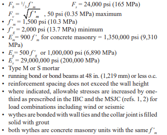
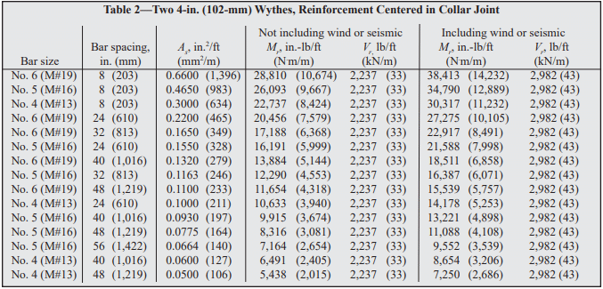
Design tables for select reinforced composite walls are included below. The tables include maximum bending moments and shear loads that can be sustained without exceeding the allowable stresses defined in the International Building Code and Building Code Requirements for Masonry Structures. These can be compared to Tables 1 and 2 of TEK 14-19B, ASD Tables for Reinforced CM Walls (2012 IBC & 2011 MSJC) (ref. 8) for wall subjected to uniform lateral loads to ensure the wall under consideration is not loaded beyond its design capacity. The examples are based on the following criteria:
The examples are based on the following criteria:
• Allowable stresses:
In addition to these tables, it is important to check all code requirements governing grout space dimensions and maximum reinforcement size to ensure that the selected reinforcing bar is not too large for the collar joint. The designer must also check shear stress at the unit/grout interface to ensure it does not exceed the code allowable stress for the design loading.
Table 2—Two 4-in. (102-mm) Wythes, Reinforcement Centered in Collar Joint
CONSTRUCTION AND DETAILING REQUIREMENTS
With composite wall construction, the two masonry wythes are not required to be built at the same time unless the collar joint is less than ¾ in. (19 mm), as the code mandates that those collar joints be mortared as the wall is built. Practically speaking it is easier to build both wythes at the same time to facilitate placing either the grout or the mortar in the collar joint at the code required pour heights.
It can be more complex to grout composite walls. Consider that a composite wall may have requirements to grout the collar joint for the full wall height and length but the cores of the concrete masonry units may only need to be partially grouted at reinforcing bar locations. Installing reinforcement and grout in the collar joint space can also be more time-consuming because of congestion due to the wall ties.
Nonmodular composite wall sections may cause diffi culty at points where they interface with modular elements such as window and door frames, bonding at corners and bonding with modular masonry walls.
NOTATIONS
As = effective cross-sectional area of reinforcement, in.²/ft (mm²/m) d = distance from extreme compression fiber to centroid of tension reinforcement, in. (mm) Eg = modulus of elasticity of grout, psi (MPa) Em = modulus of elasticity of masonry in compression, psi (MPa) Es = modulus of elasticity of steel, psi (MPa) Fb = allowable compressive stress due to flexure only, psi (MPa) Fs = allowable tensile or compressive stress in reinforcement, psi (MPa) Fv = allowable shear stress in masonry, psi (MPa) f’g = specified compressive strength of grout, psi (MPa) f’m = specified compressive strength of masonry, psi (MPa) Mr = resisting moment of wall, in.-lb/ft (kNm/m) Vr = resisting shear of wall, lb/ft (kN/m)
REFERENCES
International Building Code 2003. International Code Council, 2003.
Building Code Requirements for Masonry Structures, ACI 530-05/ASCE 5-05/TMS 402-05. Reported by the Masonry Standards Joint Committee, 2005.