The CMHA Concrete Masonry Unit Strength Method Calculator is a spreadsheet-based calculator tool to aid in determining either:
The specified compressive strength of masonry for a given CMU strength, or
The required CMU strength for a given specified compressive strength of masonry.
The calculator provides these values in accordance with either the 2013 or 2016 version of TMS 402/602, Building Code Requirements and Specification for Masonry Structures.
Structural performance of concrete masonry is largely dependent upon three key criteria:
the engineering rationale forming the basis of the structure’s design;
the physical characteristics of the materials used in the construction (i.e., the masonry units, grout, mortar, and reinforcement); and
the quality of the construction used in assembling these components.
The first step in the design of any engineered masonry structure is determining anticipated service loads. Once these loads are established, the required strength of the masonry can be determined. The designation f’m, indicates the specified compressive strength of masonry. It is used throughout the design and, in accordance with the appropriate code, to predict the strength and behavior of the masonry assembly and thus to size masonry elements. It should be stressed that the specified compressive strength of the masonry is related to but not always equal to the tested compressive strength of the masonry.
To ensure that a safe and functional structure is being constructed that will meet or exceed the intended service life, measures must be taken to verify that the compressive strength of the assembled materials (including masonry units, mortar and grout if used) meet or exceed the specified compressive strength of the masonry.
Compliance with the specified compressive strength is verified by one of three methods: the unit strength method, the prism test method, or by removing units from existing construction. These methods are referenced in masonry design codes (refs. 1, 3, 4, 6), specifications (ref. 2,4), and standards (ref. 5) as rational procedures for verifying masonry compressive strength.
UNIT STRENGTH METHOD
The unit strength method is often considered the least expensive and most convenient of the three methods. However, the unit strength method also tends to yield more conservative masonry strengths when compared to the prism test method.
Compliance with f’m by the unit strength method is based on the net area compressive strength of the units and the type of mortar used. The compressive strength of the concrete masonry assemblage is then established in accordance with Table 1 for concrete masonry designed in accordance with the 2013 Specifications for masonry Structures (MSJC) (ref. 2), and Table 2 for concrete masonry designed in accordance with the 2016 Specifications of Masonry Structures (TMS 402) (ref. 4).
Use of the unit strength method requires the following:
Concrete masonry units must be sampled and tested in accordance with ASTM C140, Standard Test Method for Sampling and Testing Concrete Masonry Units and Related Units (ref. 7) and meet the requirements of ASTM C90, Standard Specification for Loadbearing Concrete Masonry Units (ref. 8). (Note that ASTM C140 allows the test of one set of units to be applied to any number of concrete masonry units or related units of any configuration or dimension manufactured by the producer using the same materials, concrete mix design, manufacturing process, and curing method.)
Mortar bed joints used in construction must not exceed ⅝ in. thickness (15.9 mm).
If grouted masonry is used in construction, the grout must meet either the proportion or the property specification of ASTM C476, Standard Specification for Grout for Masonry (ref. 9), and the 28-day compressive strength of the grout must equal or exceed f’m but not be less than 2,000 psi (14 MPa). When property specifications are used, the compressive strength of the grout is determined in accordance with ASTM C1019, Standard Test Method for Sampling and Testing Grout (ref. 10).
Mortar must comply with requirements of ASTM C270, Standard Specification for Mortar for Unit Masonry (ref. 11).
In addition to this TEK, CMHA has generated a spreadsheet that calculates the specified compressive strength (f’m ) for masonry based on the compressive strength of the concrete masonry unit and the type of mortar used. Additionally, the spreadsheet also calculates the required strength of a unit to obtain a specific value of f’m . See CMU-XLS-004-19, CMU Unit Strength Calculator (ref. 17).
Using either Table 1 or Table 2 for example, for concrete masonry units with a compressive strength of 2,600 (17.93 MPa), the maximum f’m used in design would be 2,250 (15.51 MPa) if Type M or S mortar were used. Note that per footnote A of Table 1 and Table 2, compressive strength of masonry values must be multiplied by 85% when the unit strength is established on units less than 4 in. (102 mm) in nominal height.
When higher strength masonry materials are specified, it may be more cost effective to utilize the prism test method to demonstrate compliance with f’m due to the level of conservatism inherent in the unit strength method; i.e., the cost of prism testing are well offset by the construction savings resulting from a more economical design that takes advantage of using a higher compressive strength for the same specified materials.
Note that the unit strength values in the 2013 and 2016 Specification for Masonry Structures (i.e., those in Table 1 and Table 2) are less conservative than values in previous editions. Note that in Table 2 the minimum compressive strength allowed for Type M or S mortar and Type N mortar is set to 2,000 psi (13.79 MPa) versus the 1900 psi (13.10 MPa) listed in Table 1. This change is as a result of changes made in ASTM C90 which sets the minimum compressive strengths of both Type M or S mortar, and Type N mortar, to 2000 psi (13.79). The historical conservatism was due to two primary reasons:
The original database of tested compressive strengths was based on the testing procedures and equipment that were considerably less refined than they are today. Current ASTM C1314, Standard Test Method for Compressive Strength of Masonry Prisms (ref. 3), requirements produce more consistent and repeatable compressive strengths, particularly the requirements for more stable bearing platens on the compression testing equipment.
Historical testing procedures did not strictly control the construction, curing, and testing of the masonry prisms. As a result, a single set of materials could produce various prism test results depending the construction, curing and testing procedures used.
The database of compressive strength values used to generate the values in Table 1 and Table 2 was compiled using modern concrete masonry materials, modern test equipment, and current ASTM test procedures, providing a more realistic estimate of masonry compressive strength.
Table 1—Compressive Strength of Masonry Based on the Compressive Strength of Concrete Masonry Units and Type of Mortar Used in Construction (ref. 2)
Table 2—Compressive Strength of Masonry Based on the Compressive Strength of Concrete Masonry Units and Type of Mortar Used in Construction (ref. 4)
PRISM TEST METHOD
ASTM C1314 contains provisions for determining the compressive strength of a masonry prism: an assemblage made of representative units, mortar and grout (for grouted masonry construction). Although constructed using materials used in the project, the prism is not intended to be a reduced-scale version of the wall, but rather a quality assurance instrument to demonstrate how the masonry components work together. For this reason, prisms are typically constructed in stack bond with a full mortar bed joint, regardless of the wall construction. The tested compressive strength of the prism is corrected to account for different permissible height to thickness ratios of the prisms. This corrected strength must equal or exceed f’m. Understandably, prism testing should be undertaken before construction begins to verify that the compressive strength of the assembled materials is not less than the specified compressive strength used in the design.
Prisms should be tested at an age not greater than 28 days old to document compliance with f’m, When prisms are tested as part of an inspection program periodically during the course of construction, an earlier age, such as 3 or 7 days, is often preferred. To confidently interpret the results of these earlier age prism tests, the relationship between prism age and strength development should be determined using the materials, construction methods and testing procedures to be used throughout the job. Only when this strength/time curve is generated can early age test results be extrapolated to predict the 28-day strength.
Prism Construction
Masonry prisms are constructed using units representative of those being used in the construction. One set of prisms (containing three individual prisms) is constructed for each combination of materials and each testing age for which the compressive strength is to be determined. Note that for concrete masonry units of different configuration but from the same production lot, separate prisms are not required for each configuration. For example, if a project uses 8-in. (203-mm) and 12-in. (305-mm) units from the same lot, prisms need only be tested using either the 8-in. (203-mm) or the 12-in. (305-mm) units, but not both. ASTM C140 (ref. 7) defines a ‘lot’ as any number of concrete masonry units of any configuration or dimension manufactured by the producer using the same materials, concrete mix design, manufacturing process, and curing method. For multi-wythe masonry construction, with different units or mortar in each wythe, separate prisms should be built representative of each wythe, and tested separately. Prisms should be constructed on a flat and level location where they can remain undisturbed until they are transported for testing, at least 48 hours.
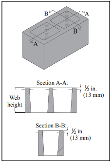
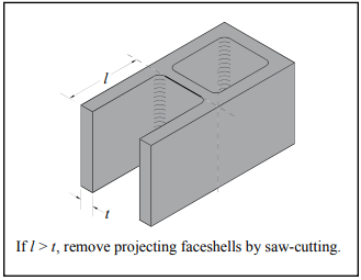
All units used to construct the prisms must be of the same configuration and oriented in the same way so that webs and face shells are aligned one on top of the other. Units are laid in stack bond on a full mortar bed using mortar representative of that used in the corresponding construction. Mortar joints are cut flush regardless of the type of mortar joint tooling used in the construction. Prisms composed of units that contain closed cells must have at least one complete cell with one full-width cross web on either end. Various prism configurations are shown in Figure 1.
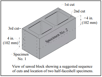
Since masonry prisms can be heavy, especially grouted prisms, it often proves effective to construct prisms using half-length units. The criteria for constructing prisms of reduced-sized units are (also see Figure 2):
that hollow units contain fully closed cells,
that the cross section is as symmetrical as possible, and
that the length is not less than 4 in. (102 mm).
As a result, handling, transporting, capping, and testing the reduced sized prisms is easier, resulting in less potential for damage to the prisms. Using reduced length prisms also reduces the required plate thicknesses for compression machines and typically result in higher and more accurate assessments of masonry strengths.
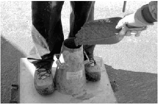
Immediately following construction of the prisms, each prism is sealed in a moisture-tight bag, as shown in Figure 3. The prism test method requires prisms to be cured in sealed plastic bags to ensure uniform hydration of the mortar and the grout if used. Under actual field conditions, it may require longer periods for hydration and the corresponding strengths to be achieved. Curing prisms in sealed plastic bags results in measured strengths which are representative of those exhibited by the masonry throughout the life of the structure. Bag curing also provides a uniform and repeatable testing procedure.
Where the corresponding construction is to be grouted solid, each prism is grouted solid using grout representative of that being used in the corresponding construction. When prisms are used for field quality control or assurance, prisms must be constructed at the same time as the corresponding construction and grouted when the construction is being grouted. When prisms are used for other purposes, such as preconstruction or for research, prism grouting must occur between 4 hours and 48 hours following the construction of the prisms.
After grouting, the grout in each prism is consolidated and reconsolidated using procedures representative of those used in the corresponding construction. After each consolidation, the grout in the prism will likely settle due to water absorption from the grout into the masonry units. Therefore, after each consolidation, additional grout should be added as necessary and be screeded level with the top of the prism to facilitate capping. Reinforcement is not included in prisms. Immediately following prism grouting, the moisture-tight bag is resealed around each prism.
If the corresponding construction will be partially grouted, two sets of prisms are constructed—one set grouted and one set ungrouted.
Figure 1—Types of Prisms
Figure 2—Saw-Cut Locations for Reduced-Size Prisms
Figure 3—Constructing a Half-Length Prism in a Plastic Bag
Transporting Prisms
Since mishandling prisms during transportation from the job site to the testing facility can have significant detrimental effects on the tested compressive strength of prisms, extreme care should be taken to protect against damage during transport.
Prior to transporting, the prisms should be strapped or clamped as shown in Figure 4 to prevent damage. Tightly clamping or strapping plywood to the top and bottom of a prism prevents the mortar joint from being subjected to tensile stresses during handling. The prisms should also be secured during transport to prevent jarring, bouncing or tipping.
Figure 4—Transporting Prisms
Curing Prisms
As previously stated, each prism is constructed in a moisture-tight bag (Figure 3) large enough to enclose and seal the completed prism. The bags should have adequate thickness to prevent tearing; a thickness of 2 mils (0.0051 mm) or greater has been found to work well. After the initial 48 hours of job site curing in the moisture-tight bag, each prism is carefully moved to a location where the temperature is maintained at 75 ± 15° F (24 ± 8° C) for full curing prior to testing.
Prism Net Cross-Sectional Area
To provide accurate an accurate strength calculation, the laboratory needs to determine the net area of the prisms. Ungrouted masonry prisms should be delivered to the testing agency with three additional units, identical to those used to construct the prism. If reduced-length prisms are used, additional reduced-length units should accompany the prisms to the laboratory for this purpose.
The net cross-sectional area used to calculate compressive strength of a prism depends on whether the prisms are grouted or ungrouted. For ungrouted full-size prisms, the cross-sectional area is the net cross-sectional area of the concrete masonry units determined in accordance with ASTM C140 on concrete masonry units identical to those used to construct the prisms. When reduced sized units are used to construct ungrouted prisms, the net cross-sectional area is based on the reduced sized units.
When testing fully grouted prisms, net cross-sectional area is determined by multiplying the actual length and width of the prism per ASTM C1314. These areas are illustrated in Figure 5.
Figure 5—Net Cross-Sectional Areas of Grouted and Ungrouted Prisms
Testing Prisms
Two days prior to the 28 day time interval or the designated testing time, typically 28 days, each prism is removed from the moisture tight bag. Prism age is determined from the time of laying units for ungrouted prisms, and from the time of grouting for grouted prisms.
To provide a smooth bearing surface, prisms are capped with either a sulfur capping material or high-strength gypsum compound in accordance with ASTM C1552, Standard Practice for Capping Concrete Masonry Units, Related Units and Masonry Prisms for Compression Testing (ref. 12). No other capping materials are permitted, nor are unbonded caps.
Capping provides level and uniform bearing surfaces for testing, thereby eliminating point loads due to surface irregularities. The result is more uniform and reliable compressive strength values. Patching of caps is not permitted because it is difficult to maintain a planar surface within the tolerances of ASTM C1552.
Capping materials must have a compressive strength of at least 3,500 psi (24.13 MPa) at an age of 2 hours when cubes of the material are tested in accordance with ASTM C617, Standard Practice for Capping Cylindrical Concrete Specimens (ref. 13).
The average thickness of the cap must not exceed ⅛ in. (3.2 mm). Caps are to be aged for at least 2 hours before testing the specimens, regardless of the type of capping material. Capping plates of adequate stiffness and smoothness are critical to achieving accurate results. Machined steel plates of 1 in. (25.4 mm) minimum thickness are required as a base. Glass plates not less than ½ in. (12.7 mm) in thickness may be used as a wearing surface to protect the plates. The capping wear plate must be plane within 0.003 in. in 16 in. (0.075 mm in 400 mm) and free of gouges, grooves and indentations greater than 0.010 in. (0.25 mm) deep or greater than 0.05 in.² (32 mm²).
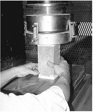
One of the most common oversights in testing masonry prisms is compliance with the established requirements for the testing machine itself. The testing machine is required to have a spherically seated head with a minimum 6 in. (150 mm) diameter and capable of rotating in any direction. The spherically seated head is then attached to a single thickness steel bearing plate having a width and length at least ¼ in. (6.4 mm) greater than the length and width of the prism being tested. The required thickness of the steel bearing plate depends on the diameter of the spherically seated head and the width and length of the prism being tested. The thickness of the steel bearing plate must equal or exceed the maximum distance from the outside of the spherically seated head to the outmost corner of the prism—designated d in Figure 6. Failure to provide the required minimum bearing plate thickness decreases the measured compressive strength of the prism due to the bearing plate bending during testing. It is also required that the bearing faces of the plates have a Rockwell hardness of at least HRC 60 (BHN 620).
The last step prior to testing a prism in compression is determining the prisms center of mass. The center of mass of a prism can be thought of as the point on the cross-section of a prism where it could physically balance on a point. The prism is then centered within the test machine such that the center of mass coincides with the center of thrust (which coincides with the center of the spherically seated head).
Failure to align the center of mass with the center of thrust results in a nonuniform application of load and therefore lower measured compressive strengths. For prisms having symmetric cross-sections, the mass centroid coincides with the geometric centroid—or the center of the prism as measured with a ruler. For prisms that are non-symmetrical about an axis, the location of that axis can be determined by balancing the masonry unit on a knife edge or a metal rod placed parallel to that axis. If a metal rod is used, the rod must be straight, cylindrical (able to roll freely on a flat surface), have a diameter between ¼ in. and ¾ in. (6.4 and 19.1 mm), and it must be longer than the specimen. Once determined, the centroidal axis can be marked on the end of the prism.
To test the prism, it is placed in the compression machine with both centroidal axes of the specimen aligned with the machine’s center of thrust. The maximum load and type of fracture is recorded. Prism strength is calculated from the maximum load divided by the prism net area. This prism strength is then corrected as described below.
Figure 6—Determination of Bearing Plate Thickness
Corrections for Prism Aspect Ratio
Since the ratio of height, hp, to least lateral dimension, tp,—designated the aspect ratio or hp/tp—of the prism can significantly affect the load carrying capacity of the masonry prism, ASTM C1314 contains correction factors for prisms having different aspect ratios, as outlined in Table 2.
To use the values in Table 2, simply multiply the measured compressive strength of the prism by the correction factor corresponding to the aspect ratio for that prism. Correction factors shown in Table 3 can be linearly interpolated between values, but cannot be extrapolated for aspect ratios less than 1.3 or greater than 5.0.
PRISMS FROM EXISTING CONSTRUCTION
The majority of quality assurance testing of concrete masonry materials is conducted on samples representative of those used in the construction. In some cases, however, it may be necessary or desirable to evaluate the properties of existing masonry construction using the actual construction materials instead of representative samples. Examples where the in-place (in-situ) masonry properties might need to be considered include old or damaged construction, or during the construction process, when: a testing variable or construction practice fails to meet specifications; a test specimen is damaged prior to testing; test records are lost; or representative samples are not otherwise available.
The procedures covered in ASTM C1532, Standard Guide for Selection, Removal, and Shipment of Manufactured Masonry Units and Specimens from Existing Construction, (ref. 14), are useful when physical examination of an assembly’s compressive strength, stiffness, flexural strength or bond strength is needed on a representative sample of the actual construction. These specimens are a portion of the existing masonry, and may include units, mortar, grout, reinforcing steel, collar joint and masonry accessories. The specimens can be taken from single or multiwythe construction. The procedures outlined in C1532 focus on documenting the condition of the masonry and protecting the specimens from damage during removal and transportation to the testing laboratory.
Standard Practice for Preparation of Field Removed Manufactured Masonry Units and Masonry Specimens for Compressive Strength Testing, ASTM C1587 (ref. 15), provides procedures for preparing field-removed specimens for compressive strength testing, and covers procedures such as removing hardened mortar and cleaning.
Compressive strength test results of field-removed masonry units and assemblies are expected to vary from, and will likely be less than, compressive strength test results of new masonry units and newly assembled prisms. Therefore, drawing relationships between the results of tests conducted on field-removed specimens to those of masonry units prior to use or of constructed prisms is difficult.
Prior to removal of specimens from existing construction, a repair plan should be developed. This plan should include replacement of units removed and repair of any disturbed or cut reinforcement, including those unintentionally damaged during the removal process.
Selecting Specimens
Specimens should be representative of the masonry construction as a whole, considering variations within the construction such as: parapets, corbels, areas where different masonry units are combined for architectural effects, as well as variations in the condition or exposure of the masonry. C1532 includes guidance on random sampling, location-specific sampling, and on condition-specific sampling. When testing to help quantify the effects of various exposures or conditions, the sampling should represent each exposure condition.
Thorough documentation of the specimen’s condition prior to removal is necessary to assess whether the specimen was subsequently damaged during removal and transport, and for comparative purposes with the other specimens.
Removing Specimens
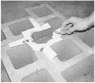
Carefully remove each specimen at its perimeter, ensuring the specimen is the appropriate size for the intended testing. Note that hydraulic or electric impact equipment should not be used, due to the potential for damaging the specimens. Saw-cutting or hand chiseling is preferred.
The following procedure is recommended. Make the first cut along the bottom of the specimen (on both sides of the wall if necessary) and insert shims. Make the two vertical cuts at the sides of the specimen, then make the top cut. Provide any necessary shoring, bracing and weather protection for the remaining construction. Similar to the pre-removal documentation, assess and document the specimen’s condition to determine if the specimen was damaged during removal.
Transporting Specimens
The specimens should be confined as described in Transporting Prisms, page 4. In addition, each specimen should be protected on all sides with material such as 1 in. (25 mm) thick packaging foam or bubble wrap, placed in sturdy crates, and the crates completely filled with packing material to ensure the specimens cannot move within the crate during transport.
Testing Specimens
It is not permitted to test grouted or partially grouted specimens that contain vertical reinforcement. Specimens cut from existing construction containing horizontal reinforcement can be tested, but the presence and location of reinforcement should be noted and reported.
Prisms must: include at least one mortar bed joint; have an aspect ratio (hp/tp) between 1.3 and 5; have a height of at least two units (each of which is at least one-half the height of a typical unit); have a length one-half the unit length and two unit lengths; not include vertical reinforcement. In addition, when prisms contain units of different sizes and/or shapes, the unit height and length are considered to be that of the largest unit height or largest unit length within the prism.
The specimens should be prepared for capping by smoothing and removing loose or otherwise unsound material from the bearing surfaces, to produce a plumb and level surface.
Note that grouted or partially grouted specimens cannot contain vertical reinforcement. The specimens are photographed to document specimen condition prior to capping. Capping and testing procedures are identical to those for constructed prisms except that a slower loading rate is used for field-removed prisms to account for uncertainty in expected loads for these prisms. For field-removed prisms, the first one-quarter of the expected load can be applied at any convenient rate, and the remaining load should be applied within 2 to 4 minutes.
Field-removed prisms may have non-uniform dimensions that should be considered when determining net cross-sectional area for calculating compressive strength. Professional judgement should be used to determine the minimum bearing area of a non-uniform prism. One effective method for face-shell bedded specimens is to multiply the length of the specimen at the bed joint by the sum of the face shell thicknesses to determine minimum bearing area. A more detailed discussion of making this determination is available in CMU-FAQ-012-14, How can the Bearing Area of a Concrete Masonry Prism Removed from Existing Construction be Determined? (ref. 16).
REFERENCES
Building Code Requirements for Masonry Structures, TMS 402-13/ACI 530-13/ASCE 5-13, Reported by the Masonry Standards Joint Committee, 2013.
Specifications for Masonry Structures, TMS 602-13/ACI 530.1-13/ASCE 6-13, Reported by the Masonry Standards Joint Committee, 2013.
Building Code Requirements for Masonry Structures, TMS 402-16, The Masonry Society, 2016.
Specification for Masonry Structures, TMS 602-16, The Masonry Society, 2016.
Standard Test Method for Compressive Strength of Masonry Prisms, ASTM C1314-16. ASTM International, Inc., 2016.
International Building Code, International Code Council, 2012/2015.
Standard Test Methods of Sampling and Testing Concrete Masonry Units and Related Units, ASTM C140/C140M-16, ASTM International, Inc., 2016.
Standard Specification for Loadbearing Concrete Masonry Units, ASTM C90-16a. ASTM International, Inc., 2016.
Standard Specification for Grout for Masonry, ASTM C476-16, ASTM International, Inc., 2016.
Standard Test Method for Sampling and Testing Grout, ASTM C1019-16, ASTM International, Inc., 2016.
Standard Specification for Mortar for Unit Masonry, ASTM C270-14a. ASTM International, Inc., 2014.
Standard Practice for Capping Concrete Masonry Units, Related Units and Masonry Prisms for Compression Testing, ASTM C1552-16, ASTM International, Inc., 2016.
Standard Practice for Capping Cylindrical Concrete Specimens, ASTM C617M-15. ASTM International, Inc., 2015.
Standard Guide for Selection, Removal, and Shipment of Manufactured Masonry Units and Specimens from Existing Construction, ASTM C1532/C1532M-12, ASTM International, Inc., 2012.
Standard Practice for Preparation of Field Removed Manufactured Masonry Units and Masonry Specimens for Testing, ASTM C1587/C1587M-15, ASTM International, Inc., 2015.
How Can the Bearing Area of a Concrete Masonry Prism Removed from Existing Construction be Determined? CMU-FAQ-014-14, Concrete Masonry & Hardscapes Association, 2014..
CMU Unit Strength Calculator, CMU-XLS-004-19, Concrete Masonry & Hardscapes Association, 2019.NCMA and the companies disseminating this technical information disclaim any and all responsibility and liability for the accuracy and the application of the information contained in this publication.
Segmental retaining wall (SRW) units are subject to the minimum requirements of Standard Specification for Dry-Cast Segmental Retaining Wall Units, ASTM C1372 (ref. 1). This standard includes criteria for minimum compressive strength, maximum water absorption, maximum permissible variations in dimensions, and, when required, freeze-thaw durability. Test methods used to demonstrate compliance with these requirements are outlined in this Tech Note.
SAMPLING SEGMENTAL RETAINING WALL UNITS
Segmental retaining wall units are sampled using the same procedures as used for other concrete masonry units. The purpose of selecting multiple test specimens for unit testing is to ensure that the range of results is representative of the entire lot of units from which the specimens were taken. Selecting units from only one portion of a pallet, or choosing only the most or least desirable units may misrepresent the properties of the lot.
Selected specimens should be randomly chosen from each lot, and should all have similar unit configurations and dimensions. A minimum of three units are required to be sampled for compression, absorption and dimensional evaluation in accordance with ASTM C140/C140M, Standard Test Method for Sampling and Testing Concrete Masonry Units and Related Units (ref. 2). When freeze-thaw durability testing is also performed, a total of five units should be selected. Since testing for compressive strength, absorption, and freeze-thaw are performed on coupon specimens, all tests can be performed on each sampled unit. Each test specimen is marked with a unique identification, which makes the test specimen immediately identifiable at any point during the testing. Immediately after marking, each unit is weighed to determine the received weight. Note that any loose material should be removed prior to weighing.
MEASUREMENT OF DIMENSIONS
Unit dimensions are measured to verify that the overall length, width and height are within the allowable ±⅛ in. (3.2 mm) tolerances permitted by ASTM C1372. This tolerance does not apply to architectural surfaces, such as split faces.
For each unit, the overall width is measured at the mid-length of the unit across the top and bottom bearing surfaces of the unit using a steel scale marked with ⅒-in. (2.5-mm) divisions (or smaller). Similarly, the overall length is measured at the mid-height at the front and back of each specimen. For height, six total measurements are taken. Four of these measurements are at each corner of the specimen, and the remaining two are taken at mid-length of the front and back of the unit (See Figure 1). The reported overall dimensions are determined by averaging the respective measurements for width and height, and reporting the front and back length of the unit separately.
Additional dimensional and testing information can be found in Segmental Retaining Wall Units, SRW-TEC-001-15 (ref. 3).
Figure 1—Height Measurements for SRW Units (ref. 2)
ABSORPTION TESTING
Absorption describes the amount of water a unit can hold when saturated. Absorption can be an indicator of the level of compaction of the concrete mix, the aggregate gradation, and the volume of voids within a unit. Data collected during absorption testing is used to calculate absorption and density. During absorption testing, the weight of each specimen is determined in the following order and condition: received weight; immersed weight; saturated weight; and oven-dry weight. The immersed and saturated weights are determined following 24 to 28 hours of immersion in water and prior to oven drying the specimens.
ASTM C140/C140M allows for absorption testing of either full units or coupons. Because of the size and weight of SRW units, coupon specimens are typically tested in lieu of full size units. When reduced-size unit are used for absorption testing, the reduced-size specimen must have an initial weight of at least 20% of the full-size unit weight. This is intended to ensure that a sufficiently sized specimen is tested in order for the results to be representative of the entire unit.
The absorption specimens are immersed in water with a temperature between 60 and 80°F (15.6 to 26.7°C) for 24 to 28 hours, and each specimen is weighed while suspended and completely submerged in water to determine the immersed weight. After determining the immersed weight, the units are removed from the tank and allowed to drain for 60 ± 5 seconds by placing them on a ⅜-in. (9.5-mm) or coarser wire mesh. A damp cloth is used to remove surface water, since a dry cloth may absorb water from the masonry unit. Each unit is weighed again to determine the saturated weight.
Testing larger specimens for absorption requires particular attention to drying times, because it takes a greater length of time to remove all of the moisture from larger masses. To reach an oven-dry condition, the units must be dried for at least 24 hours in a ventilated oven at a temperature of 221 to 239°F (105 to 115°C). For most laboratories, this means a drying time of more than 24 hours, since several hours are typically required to raise the oven temperature to the specified range after the room-temperature SRW units are inserted.
After at least 24 hours, unit weights are recorded in two-hour intervals to ensure the units are no longer losing weight due to moisture loss. The unit is considered oven dry when two successive weighings differ by 0.2% or less. Note that when weighing the units using an electronic scale, insulating materials for the scale may be necessary, because heat radiating from a unit just removed from the oven may cause the scale to return inaccurate results.
ASTM C1372 (ref. 1) includes the maximum water absorption requirements shown in Table 1.
Table 1—Maximum Water Absorption for SRW Units (ref. 1)
a Based on oven-dry density of concrete.
COMPRESSIVE STRENGTH TESTING
Compressive strength tests are used to ensure that the SRW units meet the minimum strength requirements of ASTM C1372: minimum net average compressive strength of 3,000 psi (20.7 MPa) for an average of three units with no individual unit less than 2,500 psi (17.2 MPa).
Some critical areas of compression testing that are necessary to ensure accurate testing include:
appropriate capping stations with stiff, planar plates with smooth surfaces,
compression machines with spherically seated heads and bearing plates meeting the requirements of ASTM C140/C140M (ref. 2), and
proper specimen alignment within the testing machine (specimen’s center of mass aligned with machine’s center of thrust).
ASTM C140/C140M testing procedures for compressive strength of SRW units are the same as those for conventional concrete masonry units (see TEK 18-7, ref. 4), with the exception that coupons are tested in lieu of full-size units.
The tested compressive strength can be influenced by the size and shape of the specimen tested and the location where the coupon was taken. For these reasons, it is important that all retaining wall units be tested using a similar size and shape specimen. In addition, the SRW unit supplier should be contacted for the recommended coupon sample location. Proper equipment and procedures are essential to prevent damaging the test specimen as a result of saw-cutting. Water-cooled, diamond-tipped blades on a masonry table saw are recommended. The blade should ideally have a diameter large enough to make each required cut in a single pass.
ASTM C140/C140M requires coupons to have a height to thickness ratio of 2:1 before capping and a length to thickness ratio of 4:1 (see Figure 2). The coupon width must be as close to 2 in. (51 mm) as possible based on the configuration of the unit but not less than 1.5 in. (38 mm). The preferred size is 2 x 4 x 8 in. (51 x 102 x 203 mm) (width x height x length). Coupon dimensions must be within ⅛ in. (3 mm) of the targeted dimensions. The coupon height is taken to be in the same direction as the unit height dimension. If these procedures are followed, the compressive strength of the coupon is considered to be the same as the strength of the whole unit.
Figure 2—SRW Coupon for Compressive Strength Testing
FREEZE-THAW DURABILITY
In areas where the segmental retaining wall is likely to be exposed to repeated freezing and thawing under saturated conditions, ASTM C1372 requires that freeze-thaw durability be demonstrated in one of the following ways:
proven field performance,
each of five specimens must have less than 1% weight loss after 100 cycles, or
four of five specimens must each have less than 1.5% weight loss after 150 cycles.
When required, testing is in accordance with ASTM C1262, Standard Test Method for Evaluating the Freeze-Thaw Durability of Dry-Cast Segmental Retaining Wall Units and Related Concrete Units (ref. 5), an accelerated laboratory test that provides an indication of relative performance when the units are placed in service. Testing in accordance with ASTM C1262 can be conducted using water or saline (3% sodium chloride by weight) as the test solution. ASTM C1372, however, does not require freeze-thaw evaluation in saline, recognizing that for most applications tests in water are considered sufficient. If the units are to be exposed to deicing salts on a regular basis, local project specifications should be consulted to determine if testing in saline is required.
Freeze-thaw durability test methods are prescribed because freeze-thaw durability cannot be reliably predicted based on factors such as compressive strength, absorption or concrete density. A unit’s freeze-thaw durability can be influenced by manufacturing variables such as:
aggregate type,
production methods,
cement content and
presence of admixtures; as well as field variables, including:
exposure to moisture (source, volume, frequency)
environment (drainage, exposure to shade or sunlight, exposure to salt and chemicals) and
temperature (rate of change, peak values, number of cycles, cycle lengths).
C1262 testing is carried out on five specimens representative of the entire lot. These units should be marked for identification, as for C140/C140M testing. Specimens are not permitted to be oven-dried prior to starting freeze-thaw testing.
One coupon is saw-cut from each SRW unit. The side of the coupon has a surface area 25 to 35 in.² (161 to 225 cm²) and a thickness of 1¼ in. ± 1/16 in. (32 ± 2 mm) (see Figure 3). The coupon should be cut from the exposed face of the unit (as it will be placed in service), unless that face is split, fluted, ribbed or otherwise nonplanar. In these cases, the coupon should be cut from another flat molded surface. Saw-cut coupons are then rinsed in water (not submerged), brushed with a soft bristle brush to remove residue and any loose particles, then allowed to air dry on edge for at least 48 hours.
Each specimen is placed in a container, as shown in Figure 4, with the appropriate test solution. After one hour, more liquid is added as necessary to maintain the prescribed level. After 24 hours in the container, the specimen is removed and allowed to drain for one minute on a ⅜-in. (9.5-mm) or coarser wire mesh, removing surface water with a damp cloth. The specimen is immediately weighed to determine the reference weight Wp, after which the specimen is returned to the container and additional water or saline is added if necessary prior to the cyclic freeze-thaw testing.
Specimens are then subjected to freezing and thawing cycles, as follows (see Figure 5):
Freeze cycle: 4 to 5 hr, or longer to ensure that all water is frozen, at 0 ± 10°F (-17 to -5°C) air temperature
Thaw cycle: 2.5 to 96 hr, to ensure that all ice has thawed, at 75 ± 10°F (24 ± 5°C) air temperature.
After every 20 cycles when using water (or 10 cycles using saline) any residue is collected, dried and weighed to determine the percentage weight loss, as follows:
determine weight of residue from each evaluation period, Wr, from (weight of the dried residue and filter paper) – (initial weight of the filter paper)
add Wr from each evaluation period to determine total accumulated residue weight, Wresidue
after the freeze-thaw testing is complete, dry each specimen and weigh to determine Wfinal
calculate the initial weight of the specimen from: Winitial = Wfinal + Wresidue
determine the cumulative weight loss of each residue collection interval both in grams and as a percentage of Winitial as shown in Table 2.
Figure 3—Coupon for Freeze-Thaw Durability Testing
Figure 4—Freeze-Thaw Immersion
Figure 5—Freeze-Thaw Cycle Requirements
Table 2—Procedure for Calculating Weight Loss Due to Freeze-Thaw Testing (ref. 3)
REFERENCES
Standard Specification for Dry-Cast Segmental Retaining Wall Units, C1372. ASTM International, 2017.
Standard Test Methods for Sampling and Testing Concrete Masonry Units and Related Units, ASTM C140/C140M14a. ASTM International, 2022b.
Compressive Strength Testing Variables for Concrete Masonry Units, TEK 18-07, Concrete Masonry & Hardscapes Association, 2004.
Standard Test Method for Evaluating the Freeze-Thaw Durability of Dry-Cast Segmental Retaining Wall Units and Related Concrete Units, ASTM C1262-10. ASTM International, 2010.
Two field tests are commonly performed for conventional grout—the slump test and the compressive strength test. Information about types of grout, grout properties and grout admixtures can be found in Grout for Concrete Masonry, TEK 09-04A (ref. 1). Information on grout mixing and placement is contained in Grouting Concrete Masonry Walls, TEK 03-02A (ref. 2).
SAMPLING GROUT
Grout should be sampled by a qualified technician. A minimum bulk sample size of ½ ft³ (0.014 m3) is required for slump and compressive strength tests (ref. 3). Two or more grout portions are taken at regularly spaced intervals during grout discharge, and are then combined to form a bulk sample. No more than 15 minutes should elapse between obtaining the first and last portion. To help ensure the sample is representative, the portions should be taken from the middle of the batch; no samples should be taken from the first nor last 10% of the discharge.
If sampled in the field, the incremental samples are transported to the testing location, with care to protect them from sun, wind and other potential sources of evaporation and contamination. The portions are then combined and remixed to form the bulk sample. The slump test must be started within 5 minutes of obtaining the final portion. Preparation of compressive strength specimens must begin within 15 minutes of obtaining the final portion.
GROUT CONSISTENCY
The slump test gives an indication of the consistency, water to cement ratio and/or fluidity of the field grout batch. Standard Test Method for Slump of Hydraulic-Cement Concrete, ASTM C 143 (ref. 4), provides test procedures to test grout slump in either the laboratory or the field. The measured grout slump should be between 8 and 11 in. (203 and 279 mm) to facilitate complete filling of the grout space and proper performance (ref. 5). When a 12 ft-8-in. (3.9 m) grout lift height is used as permitted in the 2005 edition of Specification for Masonry Structures (ref. 5), grout slump must be maintained between 10 and 11 in. (254 and 279 mm). When the rate of water loss may be high, such as when temperatures are elevated and/or the concrete masonry units are highly absorptive, slumps in the upper part of the range (i.e., more fluid) may be desirable, although care should be taken that the grout does not segregate because the slump is too high. High-slump grouts are advantageous when grout spaces are small or highly congested. When water will be absorbed at a slower rate, such as with lower absorptive concrete masonry units, grouts in the lower slump range are good selections. If grout spaces are large, or the lifts are short, slumps in the lower part of the range also can work well.
To perform the slump test, the cone, shown in Figures 1 and 2, is dampened and placed on a flat, rigid, nonabsorbent surface. The technician stands on the mold’s foot pieces to hold the mold firmly in place while filling the mold in three layers of equal volume (see Figure 1). The first layer should fill the mold to a depth of about 2 ⅝ in. (67 mm), the second to 6 ⅛ in. (156 mm) and the top layer should slightly overfill the mold. Each layer is rodded 25 times with a round steel tamping rod to consolidate the grout before the next layer is placed.
The middle and top layers are rodded through the depth of the layer, penetrating into the layer below. If the grout level falls below the top of the cone while rodding the top layer, grout is added to keep excess grout heaped above the top of the mold at all times. After the top layer is rodded, any excess grout is struck off flush with the top of the cone. Any grout which accumulates around the base of the mold is removed so that it does not interfere with the movement of the slumping grout.
Immediately after striking off and clearing grout from the base of the mold, the mold is lifted in 3 to 7 seconds by raising it vertically using a steady upward lift. The mold should not be twisted or moved sideways during lifting.
The slump is the vertical distance between the top of the cone and the displaced original center of the top surface of the specimen, as shown in Figure 2.
The entire test must be completed within 2 ½ minutes, from start of mold filling to measurement. If there is a decided falling away or shearing off of grout from one side or portion of the grout mass, the test should be disregarded and repeated with a fresh grout sample.
Figure 1—Filling the Slump Cone
Figure 2—Measuring Grout Slump for Conventional Grout
COMPRESSIVE STRENGTH TESTING
When grout compressive strength testing is required, the procedures of ASTM C 1019, Standard Test Method for Sampling and Testing Grout (ref. 3) are used. The Standard contains procedures for both field and laboratory grout compression testing and can be used either to help select grout proportions during preconstruction or as a quality control test for grout preparation uniformity during construction.
When used as part of a quality assurance program, the number of grout samples to be tested should be specified before the start of construction. One grout sample, as previously described, is used to make three compressive strength specimens. Grout specimens are formed in molds made from concrete masonry units with the same absorption and moisture content characteristics as those being used on the job (see Figures 3, 4).
Because the absorption characteristics of the grout mold must be similar to those experienced by the grout in the wall, when walls are constructed using both concrete and clay masonry units, the grout mold is constructed using both types of units, as shown in Figure 4.
The molds should be located where they can remain undisturbed for 24 to 48 hours, in a level area free from perceptible vibration.
Units for the mold are laid out to form a space with a square cross section, 3 in. (76 mm) or larger on each side, with a height twice its width. Nonabsorbent spacers are placed at the bottom of the square space if needed to achieve the required specimen height. Permeable liners, such as paper towels, are taped to the surrounding masonry units to break the bond between the grout specimen and the masonry units, but still allow water to be absorbed into the units.
Grout is poured into the mold in two lifts of approximately equal depth, with each layer rodded 15 times to eliminate any air bubbles, distributing the strokes uniformly over the cross section of the mold. When rodding the upper layer, the rod should penetrate about ½ in. (13 mm) into the bottom layer. After the upper layer is rodded, the top of the specimen is leveled with a straight edge as shown in Figure 5, such that there are no projections or depressions exceeding ⅛ in. (3.2 mm). The specimen is then immediately covered with damp fabric or similar material to promote curing.
Within 30 minutes of filling the mold, grout is added to completely fill any depression which may have formed due to initial water absorption. The top of the specimen is leveled again and re-covered to keep it damp until testing.
The specimens should remain undisturbed until the molds are removed, and should be protected from temperature extremes. After 24 to 48 hours, the molds are removed and the specimens are carefully packed for transport, keeping them damp, and shipped to the laboratory for testing.
Within 8 hours of removing the molds, laboratory personnel should store the specimens in a moist room, moist cabinet or water storage tank prior to testing.
Specimen width, height and out-of-plumb are measured and recorded. Average widths are used to calculate the average cross-sectional area, which is used to determine compressive strength based on the maximum compressive load.
Prior to testing, the specimens should be capped in accordance with the applicable provisions of ASTM C 617, Standard Method of Capping Cylindrical Concrete Specimens, (ref. 6), and tested according to ASTM C 39, Standard Method of Test for Compressive Strength of Molded Concrete Cylinders (ref. 7) (see Figure 6). More detail on the test method and procedures are included in ASTM C 1019.
When approved, other methods of obtaining grout samples, such as drilling cores, may be used to test grout compressive strength. Because test results vary with the method of forming the specimen and with specimen geometry, these test results cannot be directly compared unless previous testing has established a relationship between the two methods of forming and specimen geometries.
Concrete test methods should not be used for grout as they do not simulate water absorption into masonry units. Grout cubes or cylinders formed in nonabsorptive molds will give unreliable results.
Figure 3—Grout Mold for Compressive Strength Testing with Concrete Masonry Units
Figure 4—Grout Mold Constructed Using Concrete Masonry and Clay Brick
Figure 5—Leveling the Top of the Grout Specimen
Figure 6—Capped Grout Specimen Being Placed In Compression Testing Machine
SELF-CONSOLIDATING GROUTS
Self-consolidating grout (SCG) is a highly fluid and stable grout mix that is easy to place and does not require consolidation or reconsolidation. SCG is similar in nature to conventional grout, although the mix design is significantly different: proportions of constituent materials are highly controlled and admixtures (typically in the form of superplasticizers with or without viscosity modifiers) are used to produce a plastic grout with desired properties. Controlled aggregate gradation is also important to maintain fluidity without segregation, to produce a mix that results in consistent properties throughout the grout lift.
Because of the fluid nature of the material, traditional measures of consistency and flow such as the slump cone test (ASTM C 143) are not applicable to SCG.
SCG is a relatively new material, which is not yet incorporated into building codes and standards. To date, compliance has been achieved in several cases by using the grout demonstration panel option in Specification for Masonry Structures (ref. 5). Quality assurance provisions are being developed. It is anticipated that SCG testing procedures will be similar to those for self-consolidating concrete, as the two materials are very similar.
REFERENCES
Grout for Concrete Masonry, TEK 09-04A. Concrete Masonry & Hardscapes Association, 2005.
STRUCTURAL TESTING OF CONCRETE MASONRY ASSEMBLAGES
INTRODUCTION
A considerable amount of research has been conducted on concrete masonry units and assemblages in order to develop design stresses for building codes and to evaluate existing building systems. The properties of concrete masonry which are considered most important and which have been the subject of research on assemblages of concrete masonry units include: structural, fi re resistance, thermal insulation, noise insulation, and resistance to moisture penetration. This TEK is concerned with testing structural properties and reviews the kinds of loads and stresses which concrete masonry walls may be subjected to in service and the principal details of ASTM Test Methods used to investigate the structural behavior of masonry walls.
TYPES OF LOADS
Loads acting on masonry walls may be classified as vertical dead and live loads, sometimes called gravity loads, and lateral loads, these being due to wind, earthquake, earth or water pressure, etc. Vertical loads may be more or less uniformly distributed along the length of the wall or may include one or several concentrated loads which are transmitted to small areas of the wall section. Vertical loads may be centered in the same plane as the centroidal axis of the wall (concentric or axial loading) or at some distance away from this axis (eccentric loading). Eccentric loads produce bending as well as direct compressive stresses and consequently are more severe than concentric loading. Lateral loads may be uniformly distributed on the vertical surface as in the case of wind, or nonuniform according to some function of other factors, as in the case of earthquake or fluid pressure loads. Lateral loads may be concentrated and their direction may be normal or parallel to or at any intermediate angle with the wall surface. Loads may be gradually or quickly applied (impact), permanent (dead loads) or transient (wind load). Vertical and lateral loads may act simultaneously to produce a combination of axial compression and flexural stress in the masonry.
TYPES OF LOADING USED IN TESTS
Despite the variety of load types and stress conditions, masonry walls can be safety designed provided their ultimate strength in direct compression, flexure and shear is known. In developing this information the test procedures employed in the past often have varied as to specimen size, loading method and other details, but when properly presented and interpreted the results have proved to be applicable and useful. Beginning in the 1930’s, the National Bureau of Standards adopted standard methods for use in their own investigations of building constructions, these methods later forming the basis for ASTM Standard E 72, Standard Test Method for Conducting Strength Tests of Panels for Building Construction (ref. 2).
Figures 1 through 6 show schematically the general procedures used in conducting compression, flexural, and racking.
COMPRESSION
Test Methods
According to ASTM E 72, compressive strength tests are made on specimens having a height equal to the height of the wall in actual use and having a nominal width of 4 ft (1.2 m). Generally, story height walls (nominal height = 8 ft) are typical of those tested but compressive strength tests have been conducted on masonry walls over 20 ft high.
Referring to Figure 1, note that compression tests are made with the load line located a distance one-third the wall thickness from the inside face of the wall (eccentric loading) or at the central plane of the wall (axial loading). Eccentric loading is prescribed in ASTM E 72 and for many years has been preferred over axial loading by many investigators since it approximates more closely the loading condition of walls in buildings.
Loading at the central plane or centerline of the wall is true axial loading only when the wall section is geometrically and elastically symmetrical with respect to the center line.
With the advent of engineered loadbearing masonry design, simpler and less expensive test methods for determining compressive strength properties of masonry have come into wide usage: ASTM E 447, Standard Test Method for Compressive Strength of Masonry Prisms (ref. 1), and ASTM C 1314, Standard Test Method for Constructing and Testing Masonry Prisms Used to Determine Compliance with Specified Compressive Strength of Masonry (ref. 3). These tests prescribe methods for testing short compression prisms made of the same masonry units, mortar, and workmanship to be used in the construction. Although the test methods are similar, ASTM E 447 is intended for research purposes only (not for construction quality assurance purposes as is C 1314), and requires collection of additional detailed information associated with research tests.
Stresses Due to Applied Loads
The type of loading largely determines the general shape of the stress distribution diagram for the wall section. For solid walls, Figure 2, axial loading results in rectangular stress diagram, the fiber stresses being uniform over the entire cross section and equal to P/A. If the vertical load is applied eccentrically or off-center by a distance of one-sixth the wall thickness (t/6), the unit stress varies from a maximum of 2P/A at the wall face nearest the load line, to zero stress at the opposite face, Figure 2b. Eccentricity greater than t/6 would produce tensile stresses at the opposite face and a stress diagram which would show zero stress at some point between the wall faces. Eccentricity less than t/6 would result in some compression at the opposite face and a stress diagram of trapezoid shape.
In Figures 2a and 2b, the average compressive stress is the same in each case, assuming the same vertical load, but as noted, the maximum fiber stress for the eccentrically loaded wall is twice that for the axially loaded wall. A logical deduction is that a given wall will support a greater axial than eccentric load. This is borne out by tests which indicate that bending stress due to eccentric location of vertical load or other causes, reduces the ultimate vertical load capacity of masonry below its axial load strength.
FLEXURAL
The different types of loading used in testing masonry walls for flexural or transverse strength are shown in Figure 3, together with the moment and shear diagrams and formulas for calculating maximum shear, moment and deflection assuming simply supported spans. ASTM E 72 specifies a specimen width of 4 ft and either line loading applied at the outer 1/4 points of the span as shown in sketch (b) of the figure, or uniformly distributed loading shown in sketch (c). Uniform transverse loading of upright specimens such as masonry walls has become practical and more commonly used with the development of the “bag method” in which a plastic or rubberized fabric bag, interposed between the wall face and a backboard, is inflated with air to give increments of pressure against the wall until failure. Comparing the deflection formulas for the three loading methods, it will be noted that 1/4-point loading causes the greatest deflection, assuming a given moment and wall section, and from this standpoint is more severe than the other two methods. Also, any line load method produces combinations of maximum shear and moment in the same region which generally results in a lower indicated strength than would be obtained with uniform loading where the regions of maximum moment and of maximum shear are widely separated. It also appears that a test loading which does not include concentrated loads more nearly simulates the more common loads considered in design, such as wind and fluid or earth pressure.
Flexural strength of unreinforced masonry assemblages can also be measured by other ASTM methods. Method E 518, Standard Test Method for Flexural Bond Strength of Masonry (ref. 5), is intended to provide simplified and economical means for gathering comparative research data on the flexural bond strength developed with different types of masonry units and mortar or for the purpose of checking job quality control as regards materials and workmanship. Unlike ASTM E 72, Method E 518 is typically not intended for use in establishing design stresses. Specimens are small prisms laid up in stack bond and tested in a horizontal position by applying load at the third-points or by applying a uniform load by means of an inflated air bag.
Method C 1072, Standard Test Method for Measurement of Masonry Flexural Bond Strength (ref. 6) covers physical testing of each joint of masonry prisms using a bond wrench test apparatus. This method permits the measurement of multiple joints in a prism rather than the single joint tests of E 82 and E 518, making statistical evaluations easier and more cost effective. The results are used to: determine compatibility of mortars and masonry units; determine the effect on flexural bond strength of factors such as mortar properties and workmanship; and predict the flexural strength of a wall. The flexural bond strength determined using C 1072 is not typically used to predict the flexural bond strength of a wall constructed of the same material unless testing is performed to document the difference between the two; nor to determine extent of bond for a water permeance evaluation.
RACKING
Racking strength tests are performed according to the general schemes shown in Figure 4 and give an indication of the resistance of the construction to the horizontal component of shearing forces acting parallel to the wall. In the method prescribed in ASTM E 72, shown in the upper sketch, the horizontal component is equal to the load P, and the principal stress, compression acting in a diagonal line between the load point and lower right reaction, is the resultant of load P and vertical reaction Rv.
In the scheme shown in the lower sketch, the load is applied diagonally downward and the horizontal component or longitudinal shear is equal to P cosφ , approximately 0.7P since φ is usually about 45o. This alternative method is not addressed in ASTM E 72, but has often been used because it eliminates the need for tie-down rods.
Results of racking tests of masonry walls generally are given in terms of the maximum horizontal component, pounds per linear foot of wall, although the total load P may also be reported. While failure is considered to be in shear, it actually is caused by a combination of shear and secondary tensile stresses, the latter acting normal to the compressive stress. Although exceeding both the shearing and secondary tensile stresses in intensity, compressive stress is not sufficient to cause a compression-type failure.
As with compression and flexural testing, an ASTM method exists for testing shear on specimens smaller than required in ASTM E 72. In ASTM E 519, Standard Test Method for Diagonal Tension (Shear in Masonry Assemblages) (ref. 4), 4 ft by 4 ft masonry assemblages are positioned in a compression testing machine so that a compressive load is applied along one diagonal, causing a diagonal tension failure with the specimen splitting apart normal to the direction of load (see Figure 5). This method also avoids the need for a hold down force to prevent rotation of the specimen as used in the E 72 method, simplifying the analysis of the state of stress in the specimen.
IMPACT
The impact test of ASTM E 695 (ref. 7) affords a qualitative measure of the capacity of wall, floor and roof panels to resist impact loading. The impact force is obtained from the free-fall of a bag of lead shot through a path which causes it to strike the center of the panel at an angle normal to the surface. The essential details of the method as adapted to the testing of upright masonry wall panels are shown in Figure 6. Panels are typically 4 ft long and are simply supported on a span six inches less than the height of the specimen. The height of drop is increased in increments until failure occurs, but not exceeding 10 ft, and the maximum drop is the value reported.
The structural testing of masonry walls and assemblages encompasses much more than merely determining the ultimate load at failure. At each load increment, strains and deflections are carefully measured with precision instruments. at various locations on the specimen. In some procedures a load increment is applied and measurements are taken after which the load is released and measurements again taken to determine the residual strain or deflection. The specimen is examined and notes made of any cracking, crushing or other visible distress. This process is repeated at each increase in load so that when the test has been concluded the research engineer has accumulated the data needed to give a clear picture of the structural behavior of the specimen through all stages of loading.
REFERENCES
Standard Test Method for Compressive Strength for Laboratory Constructed Masonry Prisms, ASTM E 447-97. American Society for Testing and Materials, 1997.
Standard Test Method for Conducting Strength Tests of Panels for Building Construction, ASTM E 72-95. American Society for Testing and Materials, 1995.
Standard Test Method for Constructing and Testing Masonry Prisms Used to Determine Compliance with Specified Compressive Strength of Masonry, ASTM C 1314-97. American Society for Testing and Materials, 1997.
Standard Test Method for Diagonal Tension (Shear) in Masonry Assemblages, ASTM E 519-81(1993)e1. American Society for Testing and Materials, 1993.
Standard Test Method for Flexural Bond Strength of Masonry, ASTM E 518 -80(1993)e1. American Society for Testing and Materials, 1993.
Standard Test Method for Measurement of Masonry Flexural Bond Strength, ASTM C 1072-94. American Society for Testing and Materials, 1994.
Standard Test Method for Measuring Relative Resistance of Wall, Floor, and Roof Construction to Impact Loading, ASTM E 695-79(1997)e1. American Society for Testing and Materials, 1997.
Standards for sampling and testing concrete masonry units are developed by the technical committees of ASTM International in accordance with consensus procedures. These standards reflect the expert opinion of researchers, concrete masonry manufacturers, designers, contractors and others with an interest in quality standards for concrete masonry.
The most commonly used ASTM standards for concrete masonry unit testing include: Standard Test Methods for Sampling and Testing Concrete Masonry Units and Related Units, ASTM C140 (ref. 1), and Standard Test Method for Linear Drying Shrinkage of Concrete Masonry Units, ASTM C426 (ref. 2).
The purpose of selecting multiple samples for unit testing is to ensure that the range of results is representative of the entire lot of units from which the specimens were taken. Consequently, concrete masonry units chosen for testing should be randomly sampled. Choosing units from one portion of a pallet, or choosing the most or least desirable units may misrepresent the properties of the lot.
Although a shipment may consist of several different unit configurations, samples for testing should all have the same configuration and dimensions. In some cases, such as shrinkage results under ASTM C426 (ref. 2), it is generally acceptable to consider the test results of one unit configuration to be representative of units with different configurations provided they were made using the same mix design, manufacturing and curing procedures.
Units that are representative of the entire lot of units are sampled from the job site or may be sampled from the manufacturer’s storage inventory. Sampled units are marked with a unique identification and weighed.
Measurement of Dimensions
Unit dimensions are used: to verify that the overall length, width and height are within allowable tolerances; to calculate normalized web area and equivalent thickness; and to verify that face shell and cross web thicknesses meet the requirements of the appropriate unit specification (see Figure 1). Minimum face shell thickness is prescribed to address concerns such as ease of mortar placement, sufficient mortar coverage over joint reinforcement and resistance to lateral pressure from grouting. Minimum web thickness and area considerations include transfer of shear, flexural strength in the horizontal span, and resistance to tensile splitting of walls under compression.
Included in ASTM C140 since 2012 is testing to determine minimum normalized web area. Its purpose is to ensure that the unit has sufficient web material connecting the face shells. It replaces the equivalent web thickness criteria in previous versions of the standard. To determine the normalized web area, the minimum thickness and height of each web is measured and used to calculate the total web area of the unit. This total web area is divided by the nominal unit face area to determine normalized web area in in.²/ft² (mm²/m²).
Although not specified in ASTM C140 (ref. 1), the units set aside for absorption testing are typically used for measurement of unit dimensions, before the units are immersed in water. This way, the gross volume (determined from overall unit dimensions) and the net volume (determined from water displacement) for the units are both determined from the same set of test specimens.
Figure 1—measurement of Web & Face Shell Thickness
Absorption
Absorption describes the amount of water a unit can hold when saturated. Absorption can be an indicator of the level of compaction of the concrete mix or of the volume of voids within a block. For a given mix design and manufacturing and curing process, variations in absorption can be an indication of deleterious materials in the mix, mixing quality, and/or compaction of the concrete mix, which also can indicate variations in compressive strength, tensile strength, durability, laboratory procedural problems, or other causes. Data collected during absorption testing is used to calculate absorption, density, net area, net volume and equivalent thickness.
Each unit is weighed a minimum of five times in this order: received weight; immersed weight; saturated surface dry weight; and oven-dry weight (at least twice). The saturated and immersed weights should always be determined following 24 to 28 hours of immersion and prior to oven drying the units.
Because the units are immersed in water and subsequently oven-dried during absorption testing, the units used for this determination should not be used for compression testing, the results of which are influenced by unit moisture content. Six units of identical size and configuration are therefore required for ASTM C140 testing—three for compression testing and three for absorption.
Compressive Strength
Compressive strength tests are used to ensure that concrete masonry units meet the minimum strength requirements of the applicable unit specification (see ref. 11). The unit compressive strength results may also be used to verify compliance with the specified compressive strength of masonry, f’m, when using the unit strength method (ref. 4, Article 1.4 B.2.b). Unit compression tests are easier and less expensive to perform than similar tests on masonry prisms, making the unit strength method the more popular.
Some of the critical areas of compression testing that are necessary to insure accurate testing include:
Appropriate capping stations with stiff, planar plates with smooth surfaces.
Compression machines with spherically seated heads and bearing plates of adequate planeness and thickness for the size of the specimen being tested. See TEK 18-01B (ref. 8) for details and an example.
Proper specimen alignment within the testing machine (center of mass aligned with center of thrust).
For compressive strength determination, three specimens are tested. Wherever possible, full-sized units are used. However, certain modifications are permitted or required as follows:
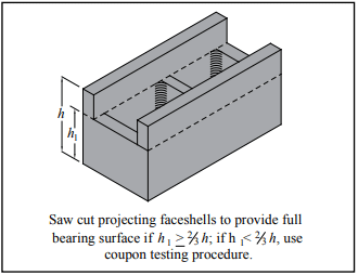
Unsupported projections with a length exceeding the projection thickness must be removed by saw-cutting (see Figure 2). For units with recessed webs, the face shell projecting above the web is removed by saw-cutting to provide a full bearing surface over the net cross-section of the unit, as shown in Figure 3.
When the size and/or strength of the unit exceeds the testing machine capacity, a specimen may be cut to conform to the testing machine capabilities. The resulting specimen, however, must contain an enclosed four-sided cell or cells without irregular face shells or webs.
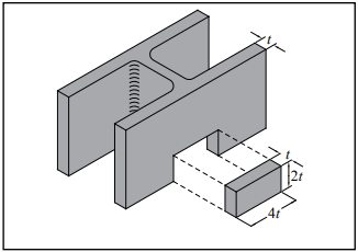
If saw-cutting does not produce a test specimen complying with the above provisions, coupons may be saw-cut from the face shells (see Figure 4).
For concrete roof paver units, cut three test specimens from three whole paver units to produce a strip of paver with the specimen height equal to its width. Where the paver has supporting ribs, cut the coupon perpendicular to the direction of the ribs, such that any bevelled or recessed surfaces are not included in the top or bottom edges of the specimen.
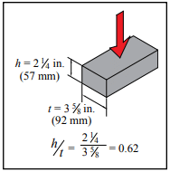
For concrete brick, specimens are required to have an aspect ratio (height divided by least lateral dimension) of 0.6 ± 0.1 (see Figure 5).
The prepared specimens are then capped in accordance with ASTM C1552 (ref. 9) to provide a uniform and level bearing surface. After the specimen center of mass is located, the specimen is positioned in the testing machine such that the specimen’s center of mass is aligned with the machine’s center of thrust. All hollow units are tested with their cores in a vertical direction, except for special units intended for use with their cores horizontal. These special units and units that are 100% solid are tested in the same direction as intended for service. Further information on compressive strength testing is available in references 8 and 12.
Figure 2—Units With Unsupported projections
Figure 3—Units With Reduced Webs
Figure 4—Coupon Requirements
Figure 5—Compression Testing of Concrete Brick
Calculations
Using the data gathered in the preceding test methods, the following characteristics are determined: absorption, density, average net area, gross area, net and gross area compressive strengths, normalized web area and equivalent thickness.
Density, or unit weight, is described in terms of dry weight per cubic foot. It is determined from the saturated weight, immersed weight and oven-dry weight. Using these weights, the volume of concrete in a unit is readily determined and its density is the oven-dry weight divided by its net volume. Among the properties affected by density of concrete in a block are wall weight, building weight, thermal conductivity, heat capacity and acoustical properties.
Cross-sectional area is the basis for expressing compressive strength of concrete masonry units. Unit specifications require that block comply with a minimum net area compressive strength. Net area is described in terms of the percentage of solid material in the cross section, and is measured by the ratio of net volume of the unit to gross volume of the unit. Because water displacement is used to determine net volume, the net cross-sectional area represents the average net area of the unit.
Equivalent thickness is used to determine the fire resistance rating. It represents the average thickness of a hollow unit if the volume is configured into a solid unit of the same face dimension. It is determined by dividing the net unit volume by the unit face area.
DRYING SHRINKAGE, ASTM C426
ASTM C426, Standard Test Method for Drying Shrinkage of Concrete Masonry Units (ref. 2) is intended to evaluate the potential shrinkage characteristics of concrete masonry units due to moisture loss only. Note that concrete masonry may also shrink due to factors such as carbonation and temperature changes, which are not addressed by this test method (although temperature is standardized and corrected so as not to influence the results). This test measures unit length change from a totally saturated condition to an “equilibrium” condition at 17% relative humidity. This represents the potential shrinkage because the masonry is unlikely to encounter these extreme conditions under normal circumstances. The test results are used to determine concrete masonry crack control provisions.
Typically, it is not necessary to run shrinkage tests on units made with the same mix design but having different unit configurations. As long as there are no changes in materials, mix design, production methods or curing, ASTM C426 tests are required to be performed only once every two years, per ASTM C90 (ref. 13).
Test specimens are usually whole units with measurements taken on both faces. Alternatively, coupons may be cut from face shells, as illustrated in Figure 6. Gage plugs are mounted on the test specimens to facilitate length measurements.
This method requires the test specimens to be saturated for 48 hours, at which time the length is precisely measured and recorded. Specimens are then dried in an oven for 5 days. After drying, specimens are cooled and measured. Test specimens are then returned to the drying oven for periods of 48 hours until the length change is negligible.
Figure 6—linear Drying Shrinkage Specimens
PREFACED UNITS
For concrete masonry units with a smooth, resinous tile-like facing adhered to the unit, Standard Specification for Prefaced Concrete and Calcium Silicate Masonry Units, ASTM C744 (ref. 3) includes requirements and applicable test methods for the facing. The concrete masonry unit to which the facing is applied must comply with the applicable unit specification. Facing requirements include:
Resistance to crazing—Units are subjected to wetting and drying to demonstrate that the facing does not craze, crack or spall. Resistance to chemicals—The facing must remain unchanged when subjected to the specified list of chemicals and exposure durations. Adhesion—The facing must remain adhered to the unit when the unit is loaded to failure by an applied compression load. Abrasion—The wear index of the facing must exceed 130 when the facing is subjected to a standard abrasion test (ASTM C501, ref. 5). Surface burning—The flame spread and smoke density rating of the facing must not exceed 25 and 50, respectively, when tested in accordance with ASTM E84 (ref. 6). Color tint & texture—The facing texture must remain unchanged and facing color difference must not exceed 5 Delta units (ref. 7) when subjected to an accelerated weathering test. Soiling and cleansability—No more than a trace of stain may remain on the facing after cleaning when subjected to a specified list of marking substances.
REFERENCES
Standard Test Methods for Sampling and Testing Concrete Masonry Units and Related Units, ASTM C140/C140M-14. ASTM International, 2014.
Standard Test Method for Linear Drying Shrinkage of Concrete Masonry Units, ASTM C426-10. ASTM International, 2010.
Standard Specification for Prefaced Concrete and Calcium Silicate Masonry Units, ASTM C744-14. ASTM International, 2014.
Specification for Masonry Structures, TMS 602-13/ACI 530.1-13/ASCE 6-13. Reported by the Masonry Standards Joint Committee, 2013.
Standard Test Method for Relative Resistance to Wear of Unglazed Ceramic Tile by the Taber Abraser, ASTM C501-84(2009). ASTM International, 2009.
Standard Test Method for Surface Burning Characteristics of Building Materials, ASTM E84-14. ASTM International, 2014.
Standard Practice for Calculation of Color Tolerances and Color Differences from Instrumentally Measured Color Coordinates, ASTM D2244-14. ASTM International, 2014.
Evaluating the Compressive Strength of CM based on 2012IBC/2011 MSJC, TEK 18-01B. Concrete Masonry & Hardscapes Association, 2011.
Standard Practice for Capping Concrete Masonry Units, Related Units and Masonry Prisms for Compression Testing, ASTM C1552-14. ASTM International, 2014.
Standard Specification for Concrete Building Brick, ASTM C55-14. ASTM International, 2014.
Concrete Masonry Unit Shapes, Sizes, Properties, and Specifications, CMU-TEC-001-23, Concrete Masonry & Hardscapes Association, 2023.
Compressive Strength Testing Variables for CM Units, TEK 18-07, Concrete Masonry & Hardscapes Association, 2004..
Standard Specification for Loadbearing Concrete Masonry Units, ASTM C90-14. ASTM International, 2014.
Structural performance of concrete masonry is largely dependent upon three key criteria:
the engineering rationale incorporated into the design of the structure;
the physical characteristics of the materials used in the construction of the structure (i.e., the masonry units, grout, mortar, and reinforcement); and
the quality of the construction used in assembling these components.
The first step in the design of any engineered masonry structure is determining anticipated service loads. Once these loads are established, the required strength of the masonry can be determined. The designation f’m, indicates the specified compressive strength of masonry. It is used throughout the design and, in accordance with the appropriate code, to predict the strength and behavior of the masonry assembly and thus to size masonry elements. It should be stressed that the specified compressive strength of the masonry is related to but not equal to the tested compressive strength of the masonry.
To ensure that a safe and functional structure is being constructed that will meet or exceed the intended service life, measures must be taken to verify that the compressive strength of the assembled materials, including masonry units, mortar and grout if used, meet or exceed the specified compressive strength of the masonry.
Compliance with the specified compressive strength is verified by one of two methods: the unit strength method or the prism test method. These two methods are referenced in masonry design codes (refs. 1, 4), specifications (ref. 2), and standards (ref. 3) as rational procedures for verifying masonry compressive strength.
UNIT STRENGTH METHOD
The unit strength method is often considered the least expensive and most convenient of the two methods. However, the unit strength method also yields more conservative masonry strengths when compared to the prism test method especially at the higher range of masonry unit strengths.
Compliance with f’m by the unit strength method is based on the net area compressive strength of the units and the type of mortar used. The compressive strength of the masonry assemblage is then established in accordance with Table 1. Table 1 is based on criteria from Specification for Masonry Structures (ref. 2) and the International Building Code (ref. 4).
According to both of these documents, use of the unit strength method requires the following:
Masonry units must be sampled and tested in accordance with ASTM C140, Standard Test Method for Sampling and Testing Concrete Masonry Units and Related Units (ref. 5) and meet the requirements of either ASTM C55, Standard Specification for Concrete Building Brick (ref. 6) or ASTM C90, Standard Specification for Loadbearing Concrete Masonry Units (ref. 7).
Thickness of bed joints used in construction must not exceed ⅝ in. (15.9 mm).
If grouted masonry is used in construction, the grout must meet either the proportion or the property specification of ASTM C476, Standard Specification for Grout for Masonry (ref. 8), and the 28-day compressive strength of the grout must equal or exceed f’m but not be less than 2,000 psi (14 MPa). When property specifications are used, the compressive strength of the grout is determined in accordance with ASTM C1019, Standard Test Method for Sampling and Testing Grout (ref. 9).
Mortar must comply with requirements of ASTM C270, Standard Specification for Mortar for Unit Masonry (ref. 10).
Since all concrete masonry units complying with ASTM C90 (ref. 7) have compressive strengths exceeding 1,900 psi (13.1 MPa), by the unit strength method any C90 unit used with Type M or S mortar can be used for projects that have f’m values up to 1,500 psi (10.3 MPa). If used with Type N mortar, any C90 unit can be used for projects having f’m values up to 1,350 psi (9.3 MPa). Conversely, if the concrete masonry units have compressive strengths of 2,800 psi (19.3 MPa), then the maximum f’m used in design would be 2,000 psi (13.8 MPa) if Type M or S mortar were used. Similarly, if 3,050 psi (21.0 MPa) concrete masonry were used in conjunction with Type N mortar, the maximum f’m that could be used in design would also be 2,000 psi (13.8 MPa). Note that per footnote A of Table 1, compressive strength of masonry values must be multiplied by 85% when the unit strength is established on units less than 4 in. (102 mm) in height.
When higher strength masonry materials are specified, it usually is more cost effective to utilize the prism test method to demonstrate compliance with f’m due to the level of conservatism inherent in the unit strength method; i.e., the costs of testing are well offset by the construction savings resulting from a more economical design that takes advantage of using a higher compressive strength for the same specified materials.
Table 1—Compressive Strength of Masonry Based on the Compressive Strength of Concrete Masonry Units and Type of Mortar Used in Construction (ref. 1)
A For units less than 4 in. (102 mm) in height, 85% of the values listed.
PRISM TEST METHOD
ASTM C1314, Standard Test Method for Compressive Strength of Masonry Prisms (ref. 3), contains provisions for determining the compressive strength of a masonry prism: an assemblage made of representative units, mortar and grout (for grouted masonry construction). Although constructed using materials used in the project, the prism is not intended to be a reduced-scale version of the wall, but rather a quality assurance instrument to demonstrate how the masonry components work together. For this reason, prisms are typically constructed in stack bond with a full mortar joint, regardless of the wall construction. The tested compressive strength of the prism is corrected to account for different permissible height to thickness ratios of the prisms. This corrected strength must equal or exceed f’m. Understandably, prism testing should be undertaken before construction begins to verify that the compressive strength of the assembled materials is not less than the specified compressive strength used in the design.
Prisms should be 28 days old to document compliance with f’m, When prisms are tested as part of an inspection program periodically during the course of construction, an earlier age, such as 3 or 7 days, is often preferred. To confidently interpret the results of these earlier age prism tests, the relationship between prism age and strength development should be determined using the materials, construction methods and testing procedures to be used throughout the job. Only when this strength/time curve is generated can early age test results be extrapolated to predict the 28-day strength.
Prism Construction
Masonry prisms are constructed using units representative of those being used in the construction. One set of prisms (containing three individual prisms) is constructed for each combination of materials and each testing age for which the compressive strength is to be determined. For multi-wythe masonry construction, with different units or mortar in each wythe, separate prisms should be built representative of each wythe, and tested separately. Prisms should be constructed on a flat and level location where they can remain undisturbed until they are transported for testing, at least 48 hours.
All units used to construct the prisms must be of the same configuration and oriented in the same way so that webs and face shells are aligned one on top of the other. Units are laid in stack bond on a full mortar bed using mortar representative of that used in the corresponding construction. Mortar joints are cut flush regardless of the type of mortar joint tooling used in the construction. Prisms composed of units that contain closed cells must have at least one complete cell with one full-width cross web on either end. Various prism configurations are shown in Figure 1.
Since masonry prisms can be heavy, especially grouted prisms, it often proves effective to construct prisms using half-length units. The criteria for constructing prisms of reduced-sized units are (also see Figure 2):
that hollow units contain fully closed cells,
that the cross section is as symmetrical as possible, and
that the length is not less than 4 in. (102 mm).
As a result, handling, transporting, capping, and testing the reduced sized prisms is easier, resulting in less potential for damage to the prisms. Using reduced-length prisms also reduces the required plate thicknesses for compression machines and typically result in higher and more accurate assessments of masonry strengths.
Immediately following construction of the prisms, each prism is sealed in a moisture-tight bag, as shown in Figure 3. The prism test method requires prisms to be cured in sealed plastic bags to ensure uniform hydration of the mortar and the grout if used. Under actual field conditions, it may require longer periods for hydration and the corresponding strengths to be achieved. Curing prisms in sealed plastic bags results in measured strengths which are representative of those exhibited by the masonry throughout the life of the structure. Bag curing also provides a uniform and repeatable testing procedure.
Where the corresponding construction is to be grouted solid, each prism is grouted solid using grout representative of that being used in the corresponding construction. When prisms are used for field quality control or assurance, prisms must be constructed at the same time as the corresponding construction and grouted when the construction is being grouted. When prisms are used for other purposes, such as preconstruction or for research, prism grouting must occur between 4 hours and 48 hours following the construction of the prisms.
After grouting, the grout in each prism is consolidated and reconsolidated using procedures representative of those used in the corresponding construction. After each consolidation, the grout in the prism will likely settle due to water absorption from the grout into the masonry units. Therefore, after each consolidation, additional grout should be added as necessary and be screeded level with the top of the prism to facilitate capping. Reinforcement is not included in prisms. Immediately following prism grouting, the moisture-tight bag is resealed around each prism.
If the corresponding construction will be partially grouted, two sets of prisms are constructed—one set grouted and one set ungrouted.
Figure 1—Types of Prisms
Figure 2—Saw-Cut Locations for Reduced-Size Prisms
Figure 3—Constructing a Half-Length Prism in a Plastic Bag
Transporting Prisms
Since mishandling prisms during transportation from the job site to the testing facility can have significant detrimental effects on the tested compressive strength of prisms, extreme care should be taken to protect against damage during transport. Prior to transporting, the prisms should be strapped or clamped as shown in Figure 4 to prevent damage. Tightly clamping or strapping plywood to the top and bottom of a prism prevents the mortar joint from being subjected to tensile stresses during handling. The prisms should also be secured during transport to prevent jarring, bouncing or tipping.
Figure 4—Transporting Prisms
Curing Prisms
As previously stated, each prism is constructed in a moisture-tight bag (Figure 3) large enough to enclose and seal the completed prism. The bags should have adequate thickness to prevent tearing; a thickness of 2 mils (0.0051 mm) or greater has been found to work well. After the initial 48 hours of job site curing in the moisture-tight bag, each prism is carefully moved to a location where the temperature is maintained at 75 ± 15° F (24 ± 8° C) for full curing prior to testing.
Prism Net Cross-Sectional Area
To provide accurate an accurate strength calculation, the laboratory needs to determine the net area of the prisms. Ungrouted masonry prisms should be delivered to the testing agency with three additional units, identical to those used to construct the prism. If reduced-length prisms are used, additional reduced-length units should accompany the prisms to the laboratory for this purpose.
The net cross-sectional area used to calculate compressive strength of a prism depends on whether the prisms are grouted or ungrouted. For ungrouted full-size prisms, the cross-sectional area is the net cross-sectional area of the masonry units determined in accordance with ASTM C140 on concrete masonry units identical to those used to construct the prisms. When reduced sized units are used to construct ungrouted prisms, the net cross-sectional area is based on the reduced sized units.
When testing fully grouted prisms, net cross-sectional area is determined by multiplying the actual length and width of the prism per ASTM C1314. These areas are illustrated in Figure 5.
Figure 5—Net Cross-Sectional Areas of Grouted and Ungrouted Prisms
Testing Prisms
Two days prior to the 28 day time interval or the designated testing time, each prism is removed from the moisture tight bag. Prism age is determined from the time of laying units for ungrouted prisms, and from the time of grouting for grouted prisms.
To provide a smooth bearing surface, prisms are capped with either a sulfur or high-strength gypsum compound in accordance with ASTM C1552, Standard Practice for Capping Concrete Masonry Units, Related Units and Masonry Prisms for Compression Testing (ref. 12). No other capping materials are permitted, nor are unbonded caps.
Capping provides level and uniform bearing surfaces for testing, thereby eliminating point loads due to surface irregularities. The result is more uniform and reliable compressive strength values. Patching of caps is not permitted because it is difficult to maintain a planar surface within the tolerances of ASTM C1552.
Capping materials must have a compressive strength of at least 3,500 psi (24.13 MPa) at an age of 2 hours when cubes of the material are tested in accordance with ASTM C617, Standard Practice for Capping Cylindrical Concrete Specimens (ref. 13).
The average thickness of the cap must not exceed ⅛ in. (3.2 mm). Caps are to be aged for at least 2 hours before testing the specimens, regardless of the type of capping material. Capping plates of adequate stiffness and smoothness are critical to achieving accurate results. Machined steel plates of 1 in. (25.4 mm) minimum thickness are required as a base. Glass plates not less than ½ in. (12.7 mm) in thickness may be used as a wearing surface to protect the plates. The capping wear plate must be plane within 0.003 in. in 16 in. (0.075 mm in 400 mm) and free of gouges, grooves and indentations greater than 0.010 in. (0.25 mm) deep or greater than 0.05 in.² (32 mm²).
One of the most common oversights in testing masonry prisms is compliance with the established requirements for the testing machine itself. The testing machine is required to have a spherically seated head with a minimum 6 in. (150 mm) diameter and capable of rotating in any direction. The spherically seated head is then attached to a single thickness steel bearing plate having a width and length at least ¼ in. (6.4 mm) greater than the length and width of the prism being tested. The required thickness of the steel bearing plate depends on the diameter of the spherically seated head and the width and length of the prism being tested. The thickness of the steel bearing plate must equal or exceed the maximum distance from the outside of the spherically seated head to the outmost corner of the prism—designated d in Figure 6. Failure to provide the required minimum bearing plate thickness decreases the measured compressive strength of the prism due to the bearing plate bending during testing. It is also required that the bearing faces of the plates have a Rockwell hardness of at least HRC 60 (BHN 620).
The last step prior to testing a prism in compression is determining the prisms center of mass. The center of mass of a prism can be thought of as the point on the cross-section of a prism where it could physically balance on a point. The prism is then centered within the test machine such that the center of mass coincides with the center of thrust (which coincides with the center of the spherically seated head).
Failure to align the center of mass with the center of thrust results in a nonuniform application of load and therefore lower measured compressive strengths. For prisms having symmetric cross-sections, the mass centroid coincides with the geometric centroid—or the center of the prism as measured with a ruler. For prisms that are non-symmetrical about an axis, the location of that axis can be determined by balancing the masonry unit on a knife edge or a metal rod placed parallel to that axis. If a metal rod is used, the rod must be straight, cylindrical (able to roll freely on a flat surface), have a diameter between ¼ in. and ¾ in. (6.4 and 19.1 mm), and it must be longer than the specimen. Once determined, the centroidal axis can be marked on the end of the prism.
To test the prism, it is placed in the compression machine with both centroidal axes of the specimen aligned with the machine’s center of thrust. The maximum load and type of fracture is recorded. Prism strength is calculated from the maximum load divided by the prism net area. This prism strength is then corrected as described below.
Figure 6—Determination of Bearing Plate Thickness
Corrections for Prism Aspect Ratio
Since the ratio of height, hp, to least lateral dimension, tp,—designated the aspect ratio or hp/tp—of the prism can significantly affect the load carrying capacity of the masonry prism, ASTM C1314 contains correction factors for prisms having different aspect ratios, as outlined in Table 2.
To use the values in Table 2, simply multiply the measured compressive strength of the prism by the correction factor corresponding to the aspect ratio for that prism. Correction factors shown in Table 3 can be linearly interpolated between values, but cannot be extrapolated for aspect ratios less than 1.3 or greater than 5.0.
Table 2—Prism Aspect Ratio Correction Factors (ref. 3)
PRISMS FROM EXISTING CONSTRUCTION
The majority of quality assurance testing of concrete masonry materials is conducted on samples representative of those used in the construction. In some cases, however, it may be necessary or desirable to evaluate the properties of existing masonry construction using the actual construction materials instead of representative samples. Examples where the in-place (in-situ) masonry properties might need to be considered include old or damaged construction, or during the construction process, when: a testing variable or construction practice fails to meet specifications; a test specimen is damaged prior to testing; test records are lost; or representative samples are not otherwise available.
The procedures covered in ASTM C1532, Standard Guide for Selection, Removal, and Shipment of Manufactured Masonry Units and Specimens from Existing Construction, (ref. 14), are useful when physical examination of an assembly’s compressive strength, stiffness, flexural strength or bond strength is needed on a representative sample of the actual construction. These specimens are a portion of the existing masonry, and may include units, mortar, grout, reinforcing steel, collar joint and masonry accessories. The specimens can be taken from single or multiwythe construction. The procedures outlined in C1532 focus on documenting the condition of the masonry and protecting the specimens from damage during removal and transportation to the testing laboratory.
C1532 is very similar to ASTM C1420, Standard Guide for Selection, Removal, and Shipment of Manufactured Masonry Units Placed in Usage (ref. 15).
Standard Practice for Preparation of Field Removed Manufactured Masonry Units and Masonry Specimens for Compressive Strength Testing, ASTM C1587 (ref. 16), provides procedures for preparing field-removed specimens for compressive strength testing, and covers procedures such as removing hardened mortar and cleaning.
Compressive strength test results of field-removed masonry units and assemblies are expected to vary from, and will likely be less than, compressive strength test results of new masonry units and newly assembled prisms. Therefore, drawing relationships between the results of tests conducted on field-removed specimens to those of masonry units prior to use or of constructed prisms is difficult.
Prior to removal of specimens from existing construction, a repair plan should be developed. This plan should include replacement of units removed and repair of any disturbed or cut reinforcement, including those unintentionally damaged during the removal process.
Selecting Specimens
Specimens should be representative of the masonry construction as a whole, considering variations within the construction such as: parapets, corbels, areas where different masonry units are combined for architectural effects, as well as variations in the condition or exposure of the masonry. C1532 includes guidance on random sampling, location-specific sampling, and on condition-specific sampling. When testing to help quantify the effects of various exposures or conditions, the sampling should represent each exposure condition.
Thorough documentation of the specimen’s condition prior to removal is necessary to assess whether the specimen was subsequently damaged during removal and transport, and for comparative purposes with the other specimens.
Removing Specimens
Carefully remove each specimen at its perimeter, ensuring the specimen is the appropriate size for the intended testing. Note that hydraulic or electric impact equipment should not be used, due to the potential for damaging the specimens. Saw-cutting or hand chiseling is preferred.
The following procedure is recommended. Make the first cut along the bottom of the specimen (on both sides of the wall if necessary) and insert shims. Make the two vertical cuts at the sides of the specimen, then make the top cut. Provide any necessary shoring, bracing and weather protection for the remaining construction. Similar to the pre-removal documentation, assess and document the specimen’s condition to determine if the specimen was damaged during removal.
Transporting Specimens
The specimens should be confined as described in Transporting Prisms, page 4. In addition, each specimen should be protected on all sides with material such as 1 in. (25 mm) thick packaging foam or bubble wrap, placed in sturdy crates, and the crates completely filled with packing material to ensure the specimens cannot move within the crate during transport.
Testing Specimens
It is not permitted to test grouted or partially grouted specimens that contain vertical reinforcement. Specimens cut from existing construction containing horizontal reinforcement can be tested, but the presence and location of reinforcement should be noted and reported.
Prisms must: include at least one mortar bed joint; have an aspect ratio (hp/tp) between 1.3 and 5; have a height of at least two units (each of which is at least one-half the height of a typical unit); have a length one-half the unit length and two unit lengths; not include vertical reinforcement. In addition, when prisms contain units of different sizes and/or shapes, the unit height and length are considered to be that of the largest unit height or largest unit length within the prism.
The specimens should be prepared for capping by smoothing and removing loose or otherwise unsound material from the bearing surfaces, to produce a plumb and level surface.
Note that grouted or partially grouted specimens cannot contain vertical reinforcement. The specimens are photographed to document specimen condition prior to capping. Capping and testing procedures are identical to those for constructed prisms.
Field-removed prisms may have non-uniform dimensions that should be considered when determining net cross-sectional area for calculating compressive strength. Professional judgement should be used to determine the minimum bearing area of a non-uniform prism. One effective method for face-shell bedded specimens is to multiply the length of the specimen at the bed joint by the sum of the face shell thicknesses to determine minimum bearing area.
REFERENCES
Building Code Requirements for Masonry Structures, ACI 530-11/ASCE 5-11/TMS 402-11. Reported by the Masonry Standards Joint Committee, 2011.
Specifications for Masonry Structures, ACI 530.1-11/ASCE 6-11/TMS 602-11. Reported by the Masonry Standards Joint Committee, 2011.
Standard Test Method for Compressive Strength of Masonry Prisms, ASTM C1314-10. ASTM International, Inc., 2010.
International Building Code, International Code Council, 2012.
Standard Test Methods of Sampling and Testing Concrete Masonry Units and Related Units, ASTM C140-11. ASTM International, Inc., 2011.
Standard Specification for Concrete Building Brick, ASTM C55-09. ASTM International, Inc., 2009.
Standard Specification for Loadbearing Concrete Masonry Units, ASTM C90-11. ASTM International, Inc., 2011.
Standard Specification for Grout for Masonry,ASTM C476-10. ASTM International, Inc., 2010.
Standard Test Method for Sampling and Testing Grout, ASTM C1019-11. ASTM International, Inc., 2011.
Standard Specification for Mortar for Unit Masonry, ASTM C270-10. ASTM International, Inc., 2010.
Standard Specification for Mortar Cement, ASTM C1329-05. ASTM International, Inc., 2005.
Standard Practice for Capping Concrete Masonry Units, Related Units and Masonry Prisms for Compression Testing, ASTM C1552-09a. ASTM International, Inc., 2009.
Standard Practice for Capping Cylindrical Concrete Specimens, ASTM C617-10. ASTM International, Inc., 2010.
Standard Guide for Seletion, Removal, and Shipment of Manufactured Masonry Units and Specimens from Existing Construction, ASTM C1532-06. ASTM International, Inc., 2006.
Standard Guide for Selection, Removal, and Shipment of Manufactured Masonry Units Placed in Usage, ASTM C1420-03. ASTM International, Inc., 2003.
Standard Practice for Preparation of Field Removed Manufactured Masonry Units and Masonry Specimens for Compressive Strength Testing, ASTM C1587-09. ASTM International, Inc., 2009.
Varying the bond or joint pattern of a concrete masonry wall can create a wide variety of interesting and attractive appearances using standard units as well as sculptured-face and other architectural units. Because concrete masonry is often used as the finished wall surface, the use of bond patterns other than the traditional running bond has steadily increased for both loadbearing and nonloadbearing walls.
Building code allowable design stresses, lateral support, and minimum thickness requirements for concrete masonry are based primarily on structural testing and research on wall panels laid in running bond construction. When a different bond pattern is used it is advisable to consider its influence on the compressive and flexural strength of a block wall. Some building codes provide for variations in bond pattern to some extent by requiring the use of horizontal reinforcement, for example, when walls are laid in stack bond.
STACK BOND CONSTRUCTION
Excluding running bond construction, the most popular and widely used bond pattern with concrete masonry units is stack bond. Compressive strength is similar for stack and running bond construction. In stack bond masonry, heavy concentrated loads will be carried down to the support by the particular vertical tier or “column” of masonry under the load, with little distribution to adjacent masonry. Stability will not be jeopardized if allowable stresses are not exceeded, but the use of reinforced bond beams will aid in distributing concentrated loads. The use of pilasters or grouted cells will also be effective in increasing the resistance to concentrated loads.
The flexural strength of stack bond walls spanning horizontally can be increased significantly by the use of bond beams or joint reinforcement. The value of joint reinforcement as a means of strengthening concrete masonry in the horizontal span is indicated in Figure 4 which shows the relative flexural strength with and without joint reinforcement. From this it can be seen that properly reinforced stack bond masonry can be designed to be as strong as running bond construction.
CODE REQUIREMENTS
Building Code Requirements for Masonry Structures (ref. 1) includes criteria for walls laid in stack bond. Although stack bond typically refers to masonry constructed such that the head joints are vertically aligned, the Code defines stack bond as masonry laid such that the head joints in successive courses are horizontally offset less than one quarter the unit length, as illustrated in Figure 1.
All stack bond construction is required to have a minimum area of horizontal reinforcement equal to 0.00028 times the gross vertical cross-sectional area of the wall. This requirement can be met using either bond beams spaced not more than 48 in. (1219 mm) on center or using joint reinforcement. Anchored masonry veneer must have horizontal joint reinforcement, of at least one wire size W1.7 (9 gauge) (MW11) or larger, spaced at a maximum of 18 in. (457 mm) on center vertically. This is equivalent to the minimum reinforcement stated above for a nominal 4 in. (102 mm) wythe.
When stack bond construction may be subjected to seismic loads or winds of hurricane velocity, consideration must be given to additional requirements and restrictions as may be consistent with local codes, local experience, and engineering practice. For example, Building Code Requirements for Masonry Structures requires stack bond masonry in Seismic Design Category D and higher to be solidly grouted hollow open-end units, fully grouted hollow units with full head joints, or solid units with a maximum spacing of 24 in. (610 mm) for the reinforcement. Seismic Design Category E & F have an additional requirement that the horizontal reinforcement be at least 0.0015 the gross cross-sectional area of walls that are not part of the lateral-force resisting system. For walls that are part of the lateral force resisting system in SDC E & F, the minimum horizontal reinforcement requirement is increased to 0.0025 times the gross cross-sectional area with a maximum spacing of 16 in. (406 mm). These elements also must be solidly grouted hollow open end units or two wythes of solid units.
Figure 1—Definition of Stack Bond Masonry
TESTING PROGRAM
To assist in evaluating the structural performance of walls laid with various bond patterns, a large number of concrete masonry panels were tested for compressive and flexural strength (ref. 2). The nine bond patterns shown in Figure 2 were employed in constructing the test panels. Panels were composed of 8 in. (203 mm) hollow units laid up with Types M and S mortar with face shell bedding. Panels were 4 ft wide by 8 ft high (1.2 by 2.4 m); those for flexural strength tests with the wall spanning horizontally between supports were 8 ft wide by 4 ft high (2.4 by 1.2 m). For compressive strength tests, loading was applied at an eccentricity of one-sixth of the wall thickness. Lateral tests used uniformly distributed loading from a plastic bag filled with air. Test methods and details followed those specified in Standard Methods of Conducting Strength Tests of Panels for Building Construction, ASTM E 72 (ref. 3)
Relative strengths of the wall panels are compared by bond pattern in Figure 3 using 8 in. (203 mm) high units laid in running bond as the standard.
Figure 2—Concrete Masonry Patterns for Structural Tests
Compressive Strengths
From Figure 3 it is evident that where hollow units are laid in the horizontal position there is no decrease in wall compressive strength for the different bonding patterns. Units laid in the vertical or diagonal position generally produce wall strengths approximately 75% of that obtained from the running bond pattern. The reduction in strength for vertical stack bond is directly related to the decrease in net block area in compression. In the vertical position, the end webs and interior webs are so oriented with respect to the direction of stress that they do not contribute to the strength of the wall except as ties between the face shells. When blocks are laid in the horizontal position, the end and middle webs are parallel to the direction of stress and contribute to the strength of the wall.
Figure 3—Relative Strengths of Walls Laid in Different Bond Patterns
Vertical Span Flexural Strength
Where walls span vertically between lateral supports, failure from transverse loading occurs as a bond failure between block and mortar. Only three of the bond patterns tested showed a decrease in flexural strength when compared to the standard: vertical stack, basket weave “B”, and coursed ashlar. In two of these patterns the continuous horizontal joints are farther apart than the standard running bond pattern. Horizontal stack bond construction was 30% stronger in vertical span flexure, and walls built with units laid in a diagonal position were more than 50% stronger because more mortar bond area is included in the “saw-tooth” line across the wall width.
Horizontal Span Flexural Strength
For unreinforced concrete masonry laid in running bond and spanning horizontally between lateral supports, flexural resistance depends on the strength and design of the block. Under increasing lateral load the units will rupture in tension rather than failing by mortar bond. For this reason, walls are generally at least twice as strong in flexure when spanning horizontally. This does not apply to walls laid in stack bond, which have approximately the same strength in both directions. Test results shown in Figure 4 indicate that the relative strength of stack bond walls in the horizontal span is about 30% of running bond construction.
Figure 4—Relative Flexural Strength in Horizontal Span of Concrete Masonry Walls With and Without Joint Reinforcement
REFERENCES
Building Code Requirements for Masonry Structures, ACI 530-02/ASCE 5-02/TMS 402-02. Reported by the Masonry Standards Joint Committee, 1999.
Masonry grout is a cementitious mixture used to fill cores or cavities in masonry construction. While usually added for structural reasons, grout can also increase: fire ratings, security, acoustical performance, termite resistance, blast resistance, thermal storage capacity and anchorage capabilities. Grout is composed of cement, aggregate, lime (optional) and sufficient water to allow ease of placement and ensure complete filling of the grout space. With approval, admixtures may be added to the grout mix. The high initial water content of typical grout mixes compensates for water absorption by the masonry during and after grout placement. The final water-to-cement ratio is significantly reduced, thus grout develops high compressive strength despite its apparent high initial water to cement ratio.
Generally, grout is used to structurally bond wall elements into a wall system. The most common example is in reinforced construction, where grout bonds the steel reinforcing bars to the masonry, allowing them to act as one system in resisting loads. Composite walls consist of two wythes of masonry with a solidly grouted collar joint with or without reinforcing steel. Grouted cores also increase the net cross sectional area of concrete masonry and permit walls to carry higher compressive, shear loads and lateral loads. Masonry cantilever retaining walls are often solidly grouted to increase the wall’s weight, and hence resistance to overturning. Grouted masonry construction is not required to be reinforced, but typically is for design economy. Reinforced masonry construction, however, requires grout to be placed around the reinforcement.
This TEK includes information about: types of grout; grout properties; grout admixtures; and self consolidating grout. Information on grout mixing and placement and on grout testing is contained in Grouting Concrete Masonry Walls, TEK 03-02A and Grout Quality Assurance, TEK 18-08B (refs. 1, 2) respectively.
SPECIFYING GROUT
Grout Type
Grout for use in concrete masonry construction should comply with ASTM C 476, Standard Specification for Grout for Masonry (ref. 3), or the governing building code which may permit grouting options other than those in set forth in ASTM C 476 . ASTM C 476 defines two types of grout: fine and coarse. Fine grout contains sand smaller than 3/8 in. (9.5 mm) as its only aggregate, while coarse grout allows pea gravel smaller than 1/2 in. (13 mm), or other acceptable aggregate, in addition to the sand.
Aggregates for grout must comply with ASTM C 404, Standard Specification for Aggregates for Masonry Grout (ref. 4), which includes requirements for grading, impurities, soundness, and methods of aggregate sampling and testing. When an aggregate does not meet the ASTM C 404 grading requirements, it may still be used provided the requirements of ASTM C 404 section 4.2 are met. These requirements prescribe minimum and maximum aggregate sizes and a minimum grout compressive strength of 2,000 psi (13.79 MPa).
Building codes and ASTM Specifications do not recognize any appreciable compressive strength difference between fine and coarse grouts. The choice of grout type therefore depends primarily on the minimum clear dimensions of the grout space, the grout pour height and construction economics. Coarse grout is typically more economical to produce. See TEK 03-02A (ref. 1) for more information on grout space requirements and grout type selection.
Grout Proportions
ASTM C 476 allows grout mixtures to be determined either by compliance with the proportions listed in Table 1 or by those established through compressive strength testing. Written acceptance of grout mix submittals is required prior to the commencement of grouting operations (ref. 7).
Using the proportions specified in Table 1 is a simple way to demonstrate compliance with ASTM C 476.
When using the specified compressive strength method in ASTM C 476, the grout must be sampled and tested in accordance with ASTM C 1019 (ref. 5) and have a minimum compressive strength of 2,000 psi (13.79 MPa) at 28 days. It must also be mixed to a slump of 8 to 11 in. (203 279 mm) as determined by ASTM C 143/143M (ref. 6). The grout proportions used to produce a grout with acceptable physical properties are then used to produce the grout for the project.
Compressive Strength
While 2,000 psi (13.79 MPa) is the minimum compressive strength required by ASTM C 476, project requirements may require higher strengths. For instance, when the unit strength method is used to determine the specified compressive strength of the masonry, f’m, Specification for Masonry Structures (ref. 7) requires the compressive strength of the grout to equal or exceed f’m but not be less than 2,000 psi (13.79 MPa). As an economic rule of thumb, unless structural criteria dictate otherwise, it is best to balance the specified grout strength with the specified concrete masonry assembly strength so that one element of the system is not considerably stronger than the other, resulting in material overstrength and design conservatism. When using the strength design provisions of the Building Code Requirements for Masonry Structures (ref. 8), a maximum specified grout compressive strength of 5,000 psi (34.47 MPa) for concrete masonry construction is applied. This limitation is based solely on the specified compressive strength of grout and does not limit the actual field-tested grout compressive strength.
Grout Slump
Grout for masonry construction is a high slump material with a flowable consistency to ease placement and facilitate consolidation. Both the Specification for Masonry Structures (ref. 7) and ASTM C476 require grout to have a slump between 8 and 11 in. (203 – 279 mm). Grout must be fluid enough to flow into the smallest grout spaces and around any obstructions, such as reinforcing bars, joint reinforcement, anchors, ties and small mortar protrusions (fins). Lower slump grouts are usually more difficult to place. Although the high slump (high initial water cement ratio of conventional grout) may concern those familiar with lower slump cementitious products such as concrete or mortar, concrete masonry units are absorptive, and the higher water content of grout is critical to insure that in-place grout has sufficient remaining water, after absorption by the masonry units, for cement hydration. Despite grout’s relatively high water to cement ratio, studies have shown that adequate grout compressive strengths and bond strengths are achieved even when using high slump grouts in wet concrete masonry units (ref. 9).
While both codes and standards specify grout slumps in excess of 8 in. (203 mm), there may be certain conditions where lower slumps could be used or may be warranted. For example, if the concrete masonry units are low absorptive units or if the grout spaces are large and the grout lifts are short, lower water content grouts may work fine although care should be taken to assure adequate filling around reinforcement or other obstructions. Likewise, cold weather could present conditions where lower water content grout would be advantageous under certain circumstances (i.e. freezing conditions), but not as a general rule. For demonstrating the suitability of alternate grouting means and/or methods, the grout demonstration panel option detailed in Specification for Masonry Structures (ref. 7) should be used to qualify the proposed method. See CMHA TEK 03-02A (ref. 1) for information on grout demonstration panels.
Production Methods
Production methods for grout are also described in ASTM C 476. These include various forms of site-mixed and ready mixed grout. When cementitious materials and aggregates are stored separately on site and then proportioned into the mixer, they are required to be mixed for at least 5 minutes in a mechanical mixer with sufficient water to bring the grout to the desired consistency. Factory dry blended cementitious materials and aggregate can also be delivered to the job site and must be mixed for the same 5 minute time period. Another option is for the individual dry ingredients to be shipped to the job site in compartments and then mixed with water on site using continuous proportioning equipment and auger mixing to the desired consistency. Grout also may arrive at the job site in a wet-mixed condition. Ready-mixed grout may have the slump adjusted at the site to bring it to the desired consistency. If water is added, the grout must be remixed for at least 1 minute before discharging. When approved by the specifier, grout may be mixed by hand instead of a mechanical mixer when only small volumes are required.
Grout quantities required on a job can vary depending on the specific circumstances of the project. The unit properties, such as absorption and configuration, can have a significant impact.
The delivery method (pumping versus bucketing) can also introduce different amounts of waste. Although the absolute volume of grout waste seen on a large project may be larger than on a comparable small project, smaller projects may experience a larger percentage of grout waste. Table 2 provides guidance for estimating grout quantities.
ADMIXTURES
A variety of admixtures is available to enhance certain grout properties. However, ASTM C 476 requires admixtures to be included in the project documents or to be approved by the purchaser. Likewise, Specification for Masonry Structures (ref. 7) requires admixtures to be accepted by the architect or engineer. Antifreeze compounds, used to lower the freezing point of grout, are prohibited by ASTM C 476. Admixtures containing chlorides should also not be used in grout, because chlorides may corrode steel reinforcement and can contribute to efflorescence in the wall. Several admixtures are available that provide a combination of desirable characteristics, such as shrinkage compensating, plasticizing and retarding. As with any admixture, manufacturer’s directions and dosage rates should be carefully followed. Note that individual admixture results can vary from one cement supplier to another.
Superplasticizers
Superplasticizing admixtures are used to reduce the water content of a plastic cementitious mix while maintaining high flow consistency. They are not normally used in conventional grout (except self consolidating grout) since the excess water is absorbed into the masonry units. In some areas, however, this absorption of excess water has resulted in efflorescence problems. Superplasticizers have been found effective in reducing this problem by reducing the amount of water available for absorption. It should be noted however, that special formulation skills are required to ensure that the grout remains fluid long enough to completely fill all the voids.
Accelerators
In grout, accelerating admixtures increase both the rate of hydration and the amount of heat generated during hydration. They are used in cold weather to decrease grout setting time and increase the rate of strength gain. The increased heat of hydration does not eliminate the need for cold weather protection requirements. Accelerators should be free of chloride materials and not perpetuate the corrosion of embedded metals.
Shrinkage Compensators
Shrinkage compensating admixtures cause a slow, controlled grout expansion that is intended to offset grout shrinkage due to the initial water loss. These admixtures may be especially useful for high-lift grouting, where a large volume of grout is placed and consolidated at one time.
Retarders
Retarding admixtures are used in hot weather to keep the grout workable long enough for placement, consolidation and reconsolidation. They may also be used when the grout cannot be placed right away, as may be the case when the plastic grout will travel a long distance to the job site.
Fly Ash and Blast-Furnace Slag
Fly ash is a by-product of coal combustion, and is not usually thought of as an admixture in the same sense as the chemical admixtures discussed above. Fly ash can be used in grout as a pumping aid or to provide a greater slump with less water. Fly ash can also replace some of the portland cement in the grout mix, which has an economic advantage since the unit cost of fly ash is less than that of portland cement.
Addition rates of fly ash and raw natural pozzolans (ref. 10) or blast furnace slag (ref. 11) are governed by ASTM C 595, Standard Specification for Blended Hydraulic Cements (ref. 12). These products can produce grout mixes with a slower initial strength gain, which may need to be considered in cold weather to achieve the minimum compressive strength previously discussed.
SELF-CONSOLIDATING GROUT
A new grout material is becoming increasingly known in North American masonry markets – self-consolidating grout (SCG). SCG is a highly fluid and stable grout mix that is easy to place and does not require consolidation or reconsolidation. SCG’s mix design is significantly different from conventional grout. SCG is similar in nature to conventional grout, with the exception that the proportions of constituent materials are highly controlled and admixtures (typically in the form of superplasticizers with or without viscosity modifiers) are used to produce a plastic grout with desired properties. Controlled aggregate gradation is also important to maintain fluidity without segregation, to produce a mix that results in consistent properties throughout the grout lift.
Because of the fluid nature of the material, traditional measures of consistency and flow such as the slump cone test (ASTM C 143) are not applicable to SCG. A slump flow test is used instead, which is an adaptation of the conventional slump cone test. In the slump flow test, SCG is loaded into an inverted slump cone. The cone is removed and the flow of the material is observed and measured. Typical slump flow spreads for SCG range from 20 to 30 in. (508-762 mm). Indications of bleeding or segregation should not be seen in the flow spread.
SCG is a relatively new material so it is not yet incorporated into building codes and standards. To date, compliance has been achieved in several cases by using the grout demonstration panel option in Specification for Masonry Structures (ref. 7). Work is under way to standardize and codify this material.
Standard Specification for Grout for Masonry, ASTM C 476-02. ASTM International, 2002.
Standard Specification for Aggregates for Masonry Grout, ASTM C 404-04. ASTM International, 2004.
Standard Test Method for Sampling and Testing Grout, ASTM C 1019-03. ASTM International, 2003.
Standard Test Method for Slump of Hydraulic-Cement Concrete, ASTM C 143/143M-03. ASTM International, 2003.
Specification for Masonry Structures, ACI 530.1-05/ASCE 6-05/TMS 602-05. Reported by the Masonry Standards Joint Committee, 2005.
Building Code Requirements for Masonry Structures, ACI 530-05/ASCE 5-05/TMS 402-05. Reported by the Masonry Standards Joint Committee, 2005.
The Effects of Concrete Masonry Unit Moisture Content on Grout Bond and Grout Compressive Strength, MR 11. Concrete Masonry & Hardscapes Association Research and Development Laboratory, 1997.
Standard Specification for Coal Fly Ash and Raw or Calcined Natural Pozzolan for Use in Concrete, ASTM C 618-03. ASTM International, 2003.
Standard Specification for Ground Granulated Blast Furnace Slag for Use in Concrete and Mortars, ASTM C 989-05. ASTM International, 2005.
Standard Specification for Blended Hydraulic Cements, ASTM C 595–03. ASTM International, 2003.
Mortarless segmental retaining walls are a natural enhancement to a variety of landscape projects. Applications range from 8 in. (204 mm) high terraces for erosion control to retaining walls 20 ft (6.1 m) or more in height. The individual concrete units can be installed to virtually any straight or curved plan imaginable.
Segmental retaining walls are used to stabilize cuts and fills adjacent to highways, driveways, buildings, patios and parking lots, and numerous other applications. Segmental retaining walls replace treated wood, cast-in-place concrete, steel, and other retaining wall systems because they are durable, easier and quicker to install, and blend naturally with the surrounding environment. Concrete units resist deterioration when exposed to the elements without the addition of toxic additives which can threaten the environment.
A variety of surface textures and features are available, including split faced, stone faced, and molded face units, any one of which may be scored, ribbed, or colored to fit any project application. Construction of segmental retaining walls does not require heavy equipment access, nor does the system require special construction skills to erect. Manufactured concrete retaining wall units generally weigh 30 to 100 lb (14 to 45 kg) each and are placed by hand on a level or sloped gravel bed.
Successive courses are stacked dry on the course below in the architectural pattern desired. Mechanical interlocking and/or frictional shear strength between courses resists lateral soil pressure. In low-height walls, overturning forces due to soil pressure are resisted by the weight of the units, sometimes aided by an incline toward the retained soil. Higher walls resist lateral soil pressures by inclining the wall toward the retained earth, or by other methods such as anchoring to geosynthetic reinforcement embedded in the soil. Further information on the design of segmental retaining walls can be found in Design Manual for Segmental Retaining Walls (ref. 1).
Segmental retaining wall units are factory-manufactured to quality standards in accordance with ASTM C1372, Standard Specification for Segmental Retaining Wall Units (ref. 2). These requirements are intended to assure lasting performance, little or no maintenance, structural integrity, and continued aesthetic value.
Segmental retaining wall units complying with the requirements of ASTM C1372 have been successfully used and have demonstrated good field performance. Segmental retaining wall units currently being supplied to the market should be produced in accordance with this standard so that both the purchaser and the supplier have the assurance and understanding of the expected level of performance of the product.
ASTM C1372 covers both solid and hollow units which are to be installed without mortar (dry-stacked). Units are designed to interlock between courses or to use mechanical devices to resist sliding due to lateral soil pressure. If particular features are desired, such as a specific weight classification, higher compressive strength, surface texture, finish, color, or other special features, they should be specified separately by the purchaser. However, local suppliers should be consulted as to the availability of units with such features before specifying them.
Figure 1—Examples of Segmental Retaining Wall Installations
Materials
ASTM C1372 includes requirements that define acceptable cementitious materials, aggregates, and other constituents used in the manufacture of concrete segmental retaining wall units. These requirements are similar to those included in ASTM C90, Standard Specification for Loadbearing Concrete Masonry Units (ref. 3).
Compressive Strength
Minimum compressive strength requirements for segmental retaining wall units are included in Table 1. Units meeting or exceeding these strengths have demonstrated the integrity needed to resist the structural demands placed on them in normal usage. These demands include impact and vibration during transportation, the weight of the units above them in the wall, nonuniform distribution of loads between units, and the tensile stresses imposed as a result of typical wall settlement.
Segmental retaining wall units will not fail in service due to compressive forces since axial loads are only a result of self-weight. Due to the direct relationship between compressive strength and tensile strength, this minimum requirement is used to ensure overall performance.
Compressive strength testing of full size units is impractical due to the large size and/or unusual shape of some segmental retaining wall units. Therefore, compressive strength of these units is determined from testing coupons cut from the units. The results of tests on these smaller coupons will typically yield lower strengths than if the larger, full-size specimen were tested. The reason for the difference is size and aspect ratio. However, it is important to keep in mind that the compression test is not intended to determine the load-carrying capacity of the unit, since segmental retaining walls are not designed to carry vertical structural loads. Compressive strength is used solely to assess the quality of the concrete.
Because tested strengths are affected by size and shape of the specimen tested, it is important that all retaining wall units be tested using a similar size and shape. ASTM C140/ C140M, Standard Method for Sampling and Testing Concrete Masonry Units and Related Units (ref. 4) requires that specimens cut from full-size units for compression testing must be a coupon with a height to thickness ratio of 2 to 1 before capping and a length to thickness ratio of 4 to 1. The coupon width is to be as close to 2 in. (51 mm) as possible based on the configuration of the unit and the capacity of the testing machine, but not less than 1.5 in. (38 mm). The preferred size is 2 x 4 x 8 in. (51 x 102 x 203 mm) (width x height x length). The coupon height is to be in the same direction as the unit height dimension. If these procedures are followed, the compressive strength of the coupon is considered the strength of the whole unit.
Alignment of the specimen in the compression machine is critical. Care should be taken in capping the test specimen to assure that capping surfaces are perpendicular to the vertical axis of the specimen. Capping needs to be performed in accordance with ASTM C1552, Standard Practice for Capping Concrete Masonry Units, Related Units and Masonry Prisms for Compression Testing (ref. 5).
Saw-cutting is the required method of extracting a test specimen from a full-size unit. Proper equipment and procedures are essential to prevent damaging the test specimen as a result of saw-cutting. Water-cooled, diamond-tipped blades on a masonry table saw are recommended. The blade should ideally have a diameter sufficient enough to make all cuts in a single pass. Manufacturers of the unit (or licensors of proprietary shapes) should be consulted about recommended locations for obtaining the compression specimen.
a Based on oven-dry density of concrete.
Weight Classification
Weight classifications for segmental retaining wall units are defined in Table 1. The three classifications, lightweight, medium weight, and normal weight, are a function of the oven dry density of the concrete. Most segmental retaining wall units fall into the normal weight category.
Absorption
Absorption requirements are also included in Table 1. This value is used to represent the volume of voids in a concrete masonry unit, including voids inside the aggregate itself. The void space is measured by determining the volume of water that can be forced into the unit under the nominal head pressure that results from immersion in a tank of water.
Lightweight aggregates used in the production of lightweight and medium weight units contain voids within the aggregate itself that also fill with water during the immersion test. While reduced voids indicate a desired tightly compacted unit, tightly compacted lightweight and medium weight units will still have higher absorption due to the voids in the aggregates. For this reason the maximum allowable absorption requirements vary according to weight classification.
Similar to compression testing, it generally is not practical to test full-size retaining wall units in absorption tests due to their size and weight. Therefore, ASTM C140/C140M permits the testing of segments saw-cut from full-size units to determine absorption and density. When reduced-size units are used for absorption testing, the reduced-size specimen must have an initial weight of at least 20% of the full-size unit weight. This is intended to ensure that a sufficiently sized specimen is tested in order for the results to be representative of the entire unit.
Absorption limits are typically expressed as mass (weight) of water absorbed per concrete unit volume. This is preferred to expressing by percentage which permits a denser unit to absorb more water than a lighter weight unit.
Testing larger specimens requires particular attention to drying times, because it takes a greater length of time to remove all moisture from larger masses. ASTM C140/C140M requires that specimens be dried for a period of not less than 24 hours at a temperature of at least 221°F (105°C). The 24-hour time period does not start until the oven reaches the specified temperature. When placing larger specimens in an oven, it may take several hours for the oven to reach the prescribed temperature. ASTM C140/C140M then requires that specimen weights be determined every two hours to make sure that the unit is not still losing water weight (maximum weight loss in two hours must be less than 0.2% of the previous specimen weight). This will require 48 hours or more for some specimens. If not adequately dried, reported absorptions will be lower than the actual value.
Permissible Variations in Dimensions
Mortarless systems require consistent unit heights to maintain vertical alignment and level of the wall. For this reason, permissible variation in dimensions is limited to ±⅛ in. (3.2 mm) from the specified standard dimensions. Regarding dimensions, “width” refers to the horizontal dimension of the unit measured perpendicular to the face of the wall. “Height” refers to the vertical dimension of the unit as placed in the wall. “Length” refers to the horizontal dimension of the unit measured parallel to the running length of the wall.
Dimensional tolerance requirements for width are waived for split faced and other architectural surfaces. The surface is intended to be rough to satisfy the architectural features desired and cannot be held to a specific tolerance.
Finish and Appearance
Minor cracks incidental to the usual method of manufacture or minor chipping resulting from customary methods of handling in shipment and delivery are not grounds for rejection. Units used in exposed wall construction are not to show chips or cracks or other imperfections in the exposed face when viewed from a distance of not less that 20 ft (6.1 m) under diffused lighting. In addition, up to five percent of a shipment are permitted to: contain chips on the finished face not larger than 1 in. (25.4 mm) in any dimension; contain cracks on the finished face wider than 0.02 in. (0.5 mm) and longer than 25% of the nominal height of the unit; have dimensions outside the permissible dimensional variations; or be broken.
Freeze-Thaw Durability
Segmental retaining wall units may be used in aggressive freezing and thawing environments. Freeze-thaw damage can occur when units are saturated with water and then undergo temperature cycles that range from above to below the freezing point of water. Freezing and thawing cycles and a constant source of moisture must both be present for potential damage to occur.
Many variations can exist in exposure conditions, any of which may affect the freeze-thaw durability performance of the units. Such variations include: maximum and minimum temperatures, rate of temperature change, duration of temperatures, sunlight exposure, directional facing, source and amount of moisture, chemical exposure, deicing material exposure, and others.
When units are used in applications where freezing and thawing under saturated conditions can occur, ASTM C1372 includes three different methods of satisfying freeze-thaw durability requirements:
Proven field performance,
Five specimens shall have less than 1% weight loss after 100 cycles in water using ASTM C1262 (ref. 6), or
Four of five specimens shall have less than 1.5% weight loss after 150 cycles in water using ASTM C1262.
Segmental retaining wall units in many areas of the country are not exposed to severe exposures. Therefore, the requirements above apply only to “areas where repeated freezing and thawing under saturated conditions occur.”
Freeze-thaw durability tests are conducted in accordance with ASTM C1262, Standard Test Method for Evaluating the Freeze-Thaw Durability of Dry-Cast Segmental Retaining Wall Units and Related Concrete Units, (ref. 6) using water or saline as the test solution. For most applications, tests in water are considered sufficient. If the units will be exposed to deicing salts on a regular basis, consideration should be given to performing the tests in saline. However, no pass/fail criteria has been adopted by ASTM for saline testing.
Compliance
ASTM C1372 also provides guidance regarding compliance. If a sample fails, the manufacturer can remove or cull units from the shipment. Then a new sample is selected by the purchaser from the remaining units of the shipment and tested, which is typically paid for by the manufacturer. If the second sample passes, then the remaining units of the lot being sampled are accepted for use in the project. If the second sample fails; however, the entire lot represented by the sample is rejected.
The specification also provides guidance on responsibility for paying for the tests. Unless otherwise provided for in the contract, the purchaser typically pays for the testing if the units pass the test. However, if the units fail the test, the seller bears the cost of the testing. See SRW-TEC-007-15Sampling and Testing Segmental Retaining Wall Units (ref. 7) for more detailed information on SRW unit sampling, testing, and acceptance.
Standard Specification for Dry Cast Segmental Retaining Wall Units, ASTM C1372-14. ASTM International, 2014.
Standard Specification for Loadbearing Concrete Masonry Units, ASTM C90-14. ASTM International, 2014.
Standard Methods for Sampling and Testing Concrete Masonry Units and Related Units, ASTM C140/C140M-14a. ASTM International, 2014.
Standard Practice for Capping Concrete Masonry Units, Related Units and Masonry Prisms for Compression Testing, ASTM C1552-14. ASTM International, 2014.
Standard Test Method for Evaluating the Freeze-Thaw Durability of Dry-Cast Segmental Retaining Wall Units and Related Concrete Units, ASTM C1262-10. ASTM International, 2010.