A wall constructed with two or more wythes of masonry can technically be classified in one of three ways, depending on how each individual wythe is designed and detailed. These three wall systems are composite, noncomposite or veneer walls. A true veneer is nonstructural—any contribution of the veneer to the wall’s out-of plane load resistance is neglected.
Building Code Requirements for Masonry Structures (ref. 1) defines veneer as a masonry wythe which provides the exterior finish of a wall system and transfers out-of-plane loads directly to the backing, but is not considered to add load resisting capacity to the wall system.
Noncomposite walls, on the other hand, are designed such that each wythe individually resists the loads imposed on it. Bending moments (flexure) due to wind or gravity loads are distributed to each wythe in proportion to its relative stiffness.
Composite walls are designed so that the wythes act together as a single member to resist structural loads. This requires that the two masonry wythes be connected by masonry headers or by a mortar or grout filled collar joint and wall ties to help ensure adequate load transfer between the two wythes.
The primary function of anchored veneers is to provide an architectural facade and to prevent water penetration into the building. As such, the structural properties of veneers are neglected in veneer design. The veneer is assumed to transfer out-of-plane loads through the anchors to the backup system. Building Code Requirements for Masonry Structures Chapter 6 (ref. 1) includes requirements for design and detailing anchored masonry veneer.
A masonry veneer with masonry backup and an air space between the masonry wythes is commonly referred to as a cavity wall. The continuous air space, or cavity, provides the wall with excellent resistance to moisture penetration and wind driven rain as well as a convenient location for insulation. This TEK addresses concrete masonry veneer with concrete masonry backup.
DESIGN CONSIDERATIONS
Masonry veneers are typically composed of architectural units such as: concrete or clay facing brick; split, fluted, glazed, ground face or scored block; or stone veneer. Most commonly, anchored masonry veneers have a nominal thickness of 4 in. (102 mm), although 3 in. (76 mm) veneer units may be available as well.
Although structural requirements for veneers are minimal, the following design considerations should be accounted for: crack control in the veneer, including deflection of the backup and any horizontal supports; adequate anchor strength to transfer applied loads; differential movement between the veneer and backup; and water penetration resistance.
The continuous airspace behind the veneer, along with flashing and weeps, must be detailed to collect any moisture that may penetrate the veneer and direct it to the outside. A minimum 1 in. (25 mm) air space between wythes is required (ref. 1), and is considered appropriate if special precautions are taken to keep the air space clean (such as by beveling the mortar bed away from the cavity or by placing a board in the cavity to catch and remove mortar droppings and fins while they are still plastic). Otherwise, a 2 in. (51 mm) air space is preferred. As an alternative, proprietary insulating drainage products can be used.
Although veneer crack control measures are similar to those for other concrete masonry wall constructions, specific crack control recommendations have been developed for concrete masonry veneers. These include: locating control joints to achieve a maximum panel length to height ratio of 11/2 and a maximum spacing of 20 ft (6,100 mm), as well as where stress concentrations occur; incorporating joint reinforcement at 16 in. (406 mm) on center; and using Type N mortar for maximum flexibility. See CMU-TEC-009-23, Crack Control Strategies for Concrete Masonry Construction (ref. 2) for more detailed information.
Because the two wythes in a veneer wall are designed to be relatively independent, crack control measures should be employed as required for each wythe. It is generally not necessary for the vertical movement joints in the veneer wythe to exactly align with those in the backup wythe, provided that the ties allow differential in-plane lateral movement.
Wall ties may be joint reinforcement or wire wall ties. Wall ties for veneers transfer lateral loads to the structural wythe and also allow differential inplane movement between wythes. This second feature is particularly important when the two wythes are of materials with different thermal and moisture expansion characteristics (such as concrete masonry and clay brick), or in an insulated cavity wall which tends to have differential thermal movement between the wythes. When horizontal joint reinforcement is used to tie the two wythes together, hot-dipped ladder type reinforcement is preferred over truss type, because the ladder shape accommodates differential in-plane movement and facilitates placing vertical reinforcement, grout and loose fill insulation. Because veneers rely on the backup for support, wall ties must be placed within 12 in. (305 mm) of control joints and wall openings to ensure the free ends of the veneer are adequately supported. More information on ties for veneers can be found in TEK 03-06C, Concrete Masonry Veneers (ref. 4).
The distance between the inside face of the veneer and the outside face of the masonry backup must be a minimum of 1 in. (25 mm) and a maximum of 4 1/2 in. (114 mm). For glazed masonry veneer, because of their impermeable nature, a 2 in. (51 mm) wide airspace is recommended with air vents at the top and bottom of the wall to enhance drainage and help equalize air pressure between the cavity and the exterior of the wall. Vents can also be installed at the top of other masonry veneer walls to provide natural convective air flow within the cavity to facilitate drying. For vented cavities, it is prudent to create baffles in the cavity at the building corners to isolate the cavities from each other. This helps prevent suction being formed in the leeward cavities.
REFERENCES
Building Code Requirements for Masonry Structures, ACI 530-02/ASCE 5-02/TMS 402-02. Reported by the Masonry Standards Joint Committee, 2002.
CMU-TEC-009-23, Crack Control Strategies for Concrete Masonry Construction, Concrete Masonry and Hardscapes Association, 2023.
TEK 03-06C, Concrete Masonry Veneers, Concrete Masonry and Hardscapes Association, 2012.
Masonry infill refers to masonry used to fill the opening in a structural frame, known as the bounding frame. The bounding frame of steel or reinforced concrete is comprised of the columns and upper and lower beams or slabs that surround the masonry infill and provide structural support. When properly designed, masonry infills provide an additional strong, ductile system for resisting lateral loads, in-plane and out-of-plane.
Concrete masonry infills can be designed and detailed to be part of the lateral force-resisting system (participating infills) or they can be designed and detailed to be structurally isolated from the lateral force-resisting system and resist only out-of-plane loads (non-participating infills).
Participating infills form a composite structural system with the bounding frame, increasing the strength and stiffness of the wall system and its resistance to earthquake and wind loads.
Non-participating infills are detailed with structural gaps between the infill and the bounding frame to prevent the unintended transfer of in-plane loads from the frame into the infill. Such gaps are later sealed for other code requirements such as weather protection, air infiltration, energy conservations, etc.
Construction of concrete masonry infilled frames is relatively simple. First, the bounding frame is constructed of either reinforced concrete or structural steel, then the masonry infill is constructed in the portal space. This construction sequence allows the roof or floor to be constructed prior to the masonry being laid, allowing for rapid construction of subsequent stories or application of roofing material.
The 2011 edition of Building Code Requirements for Masonry Structures (MSJC Code, ref. 1) includes a new mandatory language Appendix B for the design of masonry infills that can be either unreinforced or reinforced. Appendix B provides a straightforward method for the design and analysis of both participating and non-participating infills. Requirements were developed based on experimental research as well as field performance.
MASONRY INFILL LOAD RESPONSE
Several stages of in-plane loading response occur with a participating masonry infill system. Initially, the system acts as a monolithic cantilever wall whereby slight stress concentrations occur at the four corners, while the middle of the panel develops an approximately pure shear stress state. As loading continues, separation occurs at the interface of the masonry and the frame members at the off-diagonal corners. Once a gap is formed, the stresses at the tensile corners are relieved while those near the compressive corners are increased.
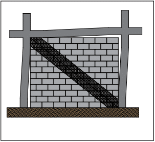
As loading continues, further separation between the masonry panel and the frame occurs, resulting in contact only near the loaded corners of the frame. This results in the composite system behaving as a braced frame, which leads to the concept of replacing the masonry infill with an equivalent diagonal strut, as shown in Figure 1. These conditions are addressed in the masonry standard.
Participating masonry infills resist out-of-plane loads by an arching mechanism. As out-of-plane loads increase beyond the elastic limit, flexural cracking occurs in the masonry panel. This cracking (similar to that which occurs in reinforced masonry) allows for arching action to resist the applied loads, provided the infill is constructed tight to the bounding frame and the infill is not too slender.
Figure 1—Concrete Masonry Infill as a Diagonal Strut
IN-PLANE SHEAR FOR PARTICIPATING INFILLS
For participating infills, the masonry is either mortared tight to the bounding frame so that the infill receives lateral loads immediately as the frame displaces, or the masonry is built with a gap such that the bounding frame deflects slightly before it bears upon the infill. If a gap exists between the infill and the frame, the infill is considered participating if the gap is less than ⅜ in. (9.5 mm) and the calculated displacements, according to MSJC Code Section B3.1.2.1. However, the infill can still be designed as a participating infill, provided the calculated strength and stiffness are reduced by half.
The maximum height-to-thickness ratio (h/t) of the participating infill is limited to 30 in order to maintain stability. The maximum thickness allowed is one-eighth of the infill height.
The MSJC Code requires participating infills to fully infill the bounding frame and have no openings—partial infills or infills with openings may not be considered as part of the lateral force resisting system because structures with partial infills have typically not performed well during seismic events. The partial infill attracts additional load to the column due to its increased stiffness; typically, this results in shear failure of the column.
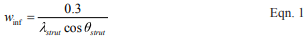
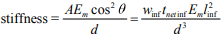
The in-plane design is based on a braced frame model, with the masonry infill serving as an equivalent strut. The width of the strut is determined from Equation 1 (see Figure 1).
where:
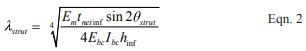
The term λstrut, developed by Stafford Smith and Carter (ref. 2) in the late 60s, is the characteristic stiffness parameter for the infill and provides a measure of the relative stiffness of the frame and the infill. Design forces in the equivalent strut are then calculated based on elastic shortening of the compression-only strut within the braced frame. The area of the strut used for that analysis is determined by multiplying the strut width from Equation 1 by the specified thickness of the infill.
The infill capacity can be limited by shear cracking, compression failure, and flexural cracking. Shear cracking can be characterized by cracking along the mortar joints (which includes st epped and horizontal cracks) and by diagonal tensile cracking. The compression failure mode consists of either crushing of the masonry in the loaded diagonal corners or failure of the equivalent diagonal strut. The diagonal strut is developed within the panel as a result of diagonal tensile cracking. Flexural cracking failure is rare because separation at the masonry-frame interface usually occurs first; then, the lateral force is resisted by the diagonal strut.
As discussed above, the nominal shear capacity is determined as the least of: the capacity infill corner crushing; the horizontal component of the force in the equivalent strut at a racking displacement of 1 in. (25 mm); or, the smallest nominal shear strength from MSJC Code Section 3.2.4, calculated along a bed joint. The displacement limit was found to be a better predictor of infill performance than a drift limit.
Generally, the infill strength is reached at lower displacements for stiff bounding columns, while more flexible columns result in the strength being controlled at the 1-in. (25-mm) displacement limit. While MSJC Code Section 3.2 is for unreinforced masonry, use of equations from that section does not necessarily imply that the infill material must be unreinforced. The equations used in MSJC Code Section 3.2 are more clearly related to failure along a bed joint and are therefore more appropriate than equations from MSJC Code Section 3.3 for reinforced masonry.
The equations used in the code are the result of comparing numerous analytical methods to experimental results. They are strength based. The experimental results used for comparison were a mixture of steel and reinforced concrete bounding frames with clay and concrete masonry. While some methods presented by various researchers are quite complex, the code equations are relatively simple.
OUT-OF-PLANE FLEXURE FOR PARTICIPATING INFILLS
The out-of-plane design of participating infills is based on arching of the infill within the frame. As out-of-plane forces are applied to the surface of the infill, a two-way arch develops, provided that the infill is constructed tight to the bounding frame. The code equation models this two-way arching action.
As previously mentioned, the maximum thickness allowed for calculation for the out-of-plane capacity is one-eighth of the infill height. Gaps between the bounding frame on either the sides or top of the infill reduce the arching mechanism to a one-way arch and are considered by the code equations. Bounding frame members that have different cross sectional properties are accounted for by averaging their properties for use in the code equations.
NON-PARTICIPATING INFILLS
Because non-participating infills support only out-of-plane loads, they must be detailed to prevent in-plane load transfer into the infill. For this reason, MSJC Code Section B.2.1 requires these infills to have isolation joints at the sides and the top of the infill. These isolation joints must be at least ⅜ in. (9.5 mm) and sized to accommodate the expected design displacements of the bounding frame, including inelastic deformation due to a seismic event, to prevent the infill from receiving in-plane loadings. The isolation joints may contain filler material as long as the compressibility of the material is taken into consideration when sizing the joint.
Mechanical connectors and the design of the infill itself ensure that non-participating infills support out-of-plane loads. Connectors are not allowed to transmit in-plane loads. The masonry infill may be designed to span vertically, horizontally, or both. The masonry design of the non-participating infill is carried out based on the applicable MSJC Code sections for reinforced or unreinforced masonry (Section 3.2 for unreinforced infill and Section 3.3 for reinforced infill using strength design methods). Note that there are seismic conditions which may require the use of reinforced masonry.
Because they support only out-of-plane loads, non-participating infills can be constructed with full panels, partial height panels, or panels with openings. The corresponding effects on the bounding frame must be included in the design.
BOUNDING FRAME FOR PARTICIPATING INFILLS
The MSJC Code provides guidance on the design loads applied to the bounding frame members; however, the actual member design is governed by the appropriate material code and is beyond the scope of the MSJC Code.
The presence of infill within the bounding frame places localized forces at the intersection of the frame members. MSJC Code Section B.3.5 helps the designer determine the appropriate augmented loads for designing the bounding frame members. Frame members in bays adjacent to an infill, but not in contact with the infill, should be designed for no less than the forces (shear, moment, and axial) from the equivalent strut frame analysis. In the event of infill failure, the loading requirement on adjacent frame members ensures adequacy in the frame design, thus preventing progressive collapse.
The shear and moment applied to the bounding column must be at least the results from the equivalent strut frame analysis multiplied by a factor of 1.1. The axial loads are not to be less than the results of that analysis. Additionally, the horizontal component of the force in the equivalent strut is added to the design shear for the bounding column.
Similarly, the shear and moment applied to the bounding beam or slab must be at least the results from the equivalent strut frame analysis multiplied by a factor of 1.1, and the axial loads are not to be less than the results of that analysis. The vertical component of the force in the equivalent strut is added to the design shear for the bounding beam or slab.
The bounding frame design should also take into consideration the volumetric changes in the masonry infill material that may occur over time due to normal temperature and moisture variations. Shrinkage of concrete masonry infill material may open gaps between the infill and the bounding frame that need to be addressed. Guidance for these volumetric changes is provided in MSJC Code Section 1.7.5.
CONNECTORS
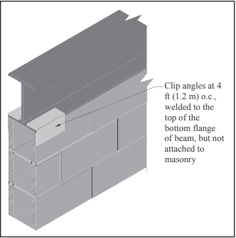
Mechanical connectors between the bounding frame and the infill provide out-of-plane support of the masonry, for both participating and non-participating infills. Connectors are required only for the direction of span (i.e., at the top and bottom of the infill for infill spanning vertically, for example). The connectors must be designed to support the expected out-of-plane loads and may not be spaced more than 4 ft (1.2 m) apart along the perimeter of the infill. Figure 2 shows an example of a mechanical connector composed of clip angles welded to the bottom flange of the steel beam.
Connectors for both participating and non-participating infills are not permitted to transfer in-plane loads from the bounding frame to the infill. For participating infills, in-plane loads are assumed to be resisted by a diagonal compression strut (see Figure 1), which does not rely upon mechanical connectors to transfer in-plane load. Research (ref. 3) has shown that when connectors transmit in-plane loads they create regions of localized stress and can cause premature damage to the infill. This damage then reduces the infill’s out-of-plane capacity because arching action is inhibited.
Figure 2—Example of Mechanical Infill Connector
EXAMPLE 1: DESIGN OF PARTICIPATING MASONRY INFILL WALL FOR IN-PLANE LOADS
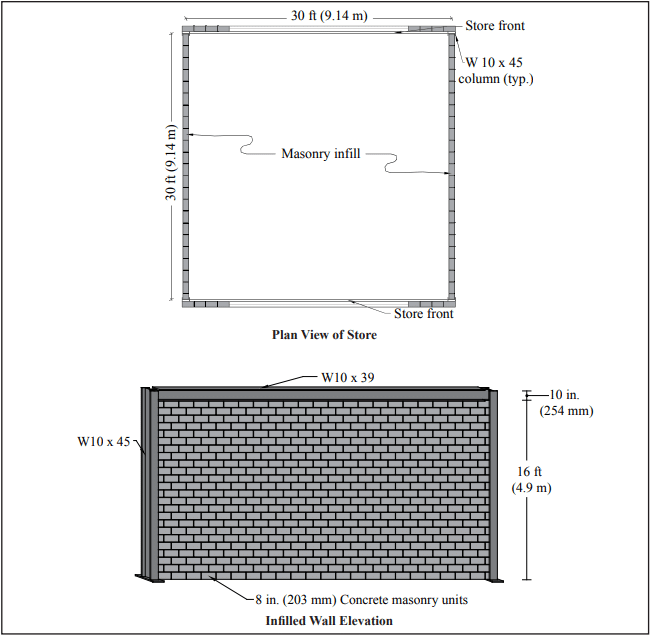
Consider the simple structure of Figure 3. The east and west side walls are concrete masonry infills laid in running bond, while the north and south walls are store-fronts typical of convenience stores. Steel frames support all gravity loads and the lateral load in the east-west direction. The bounding columns are W10x45s oriented with the strong axis in the east-west direction. The bounding beams above the masonry infill are W10x39s. The masonry infill resists the lateral load in the north-south direction.
Use nominal 8-in. (203-mm) concrete masonry units, f’m = 1,500 psi (10.34 MPa), and Type S PCL mortar. Assume hollow units with face-shell bedding only. The total wall height measures 16 ft-10 in. (5.1 m) to the roof with the infill being 16 2 ft (4.9 m). The building is loaded with a wind load of 24 lb/ft² calculated per ASCE 7-10 (ref. 6) in the north-south direction. The roof acts as a one-way system, transmitting gravity loads to the north and south roof beams. Infill and bounding beam properties are summarized in Tables 1 and 2.
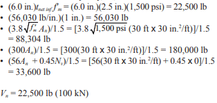
MSJC Code Section B.3.4.3 requires Vn inf to be the smallest of the following:
(6.0 in.)tnet inff’m
the calculated horizontal component of the force in the equivalent strut at a horizontal racking displacement of 1.0 in. (25 mm)
Vn/1.5, where Vn is the smallest nominal shear strength from MSJC Code Section 3.2.4, calculated along a bed joint.
MSJC Code Section 3.2.4 requires the nominal shear strength not exceed the least of the following:
3.8 An √f ′m
300An
56An + 0.45Nv for running bond masonry not fully grouted and for masonry not laid in running bond, constructed of open end units, and fully grouted
90An + 0.45Nv for running bond masonry fully grouted
23An for masonry not laid in running bond, constructed of other than open end units, and fully grouted
Figure 3—Convenience Store Layout for Design Examples 1 & 2
Table 1—Infill Properties
Table 2—Bounding Frame Properties for In-Plane Loads
As a result of the wind loading, the reaction transmitted to the roof diaphragm is:
Reaction = ½ (24lb/ft²)(16.83 ft) = 202 lb/ft (2.95 kN/m)
Total roof reaction acting on one side of the roof is Reaction = (202 lb/ft)(30 ft) = 6,060 lb (27.0 kN)
This reaction is divided evenly between the two masonry infills, so the shear per infill is 3,030 lb (13.5 kN).
Using the conservative loading case of 0.9D + 1.0W, Vu = 1.0 Vunfactored = 1.0 (3,030 lb) = 3,030 lb (13.5 kN)
To be conservative, the axial load to the masonry infill is taken as zero.
To ensure practical conditions for stability, the ratio of the nominal vertical dimension to the nominal thickness is limited to 30 for participating infills. The ratio for this infill is: h/t = 192 in./8 in. = 24 < 30 The ratio is less than 30 and the infill is therefore acceptable as a participating infill.
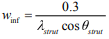
The width of the equivalent strut is calculated by Equation 1 (MSJC Code Equation B-1):
where λstrut is given by Equation 2 (Code Equation B-2).
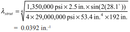
The angle of the equivalent diagonal strut, θstrut, is the angle of the infill diagonal with respect to the horizontal. θstrut = tan-1 (hinf/linf) = tan-1 (192 in./360 in.) = 28.1°
Using Equation 2, the characteristic stiffness parameter, λstrut, for this infill is then:
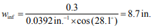
The resulting strut width is then:
The stiffness of the equivalent braced frame is determined by a simple braced frame analysis where the stiffness is based on the elastic shortening of the diagonal strut. The strut area is taken as the width of the strut multiplied by the net thickness of the infill.
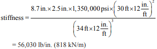
The stiffness is:
where d is the diagonal length of the infill, 34 ft (10.3 m) in this case.
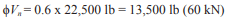
The nominal shear capacity, Vn, is then the least of:
The design shear capacity is:
The design shear capacity far exceeds the factored design shear of 3,030 lb (13.5 kN), so the infill is satisfactory for shear.
Additionally, the provisions of MSJC Code Section B.3.5 require that the designer consider the effects of the infill on the bounding frame. To ensure adequacy of the frame members and connections, the shear and moment results of the equivalent strut frame analysis are multiplied by a factor of 1.1. The column designs must include the horizontal component of the equivalent strut force, while the beam designs must include the verti cal component of the equivalent strut force. The axial forces from the equivalent strut frame analysis must also be considered in both the column and beam designs.
EXAMPLE 2: DESIGN OF PARTICIPATING MASONRY INFILL WALL FOR OUT-OF-PLANE LOADS
Design the infill from the previous example for an out-of-plane wind load W of 24 lb/ft² (1.2 kPa) per ASCE 7-10 acting on the east wall, using Type S PCL mortar, and units with a nominal thickness of 8 in. (203 mm). Assume hollow units with face-shell bedding only and that the infill is constructed tight to the bounding frame such that there are no gaps at the top or sides of the infill. See Table 3 for frame properties.
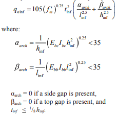
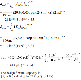
MSJC Code Section B.3.6 provides the equations for the nominal out-of-plane flexural capacity. MSJC Code Equation B-5 requires that the flexural capacity of the infill be:
Using the conservative loading case of 0.9D + 1.0W, the design wind load pressure is:
q = 1.0W = 1.0 x 24 psf = 24 psf (1.15 kPa) tinf = 7.625 in. < (⅛)(192 in.), OK
The design flexural capacity exceeds the factored design wind load pressure of 24 lb/ft² (1.2 kPa), so the infill is satisfactory for out-of-plane loading
Table 3—Bounding Frame Properties for Out-of Plane Loads
NOTATIONS
An = net cross-sectional area of a member, in.² (mm²) D = dead load, psf (Pa) d = diagonal length of the infill, in. (mm) Ebb = modulus of elasticity of bounding beams, psi (MPa) Ebc = modulus of elasticity of bounding columns, psi (MPa) Em = modulus of elasticity of masonry in compression, psi (MPa) f’m = specified compressive strength of masonry, psi (MPa) h = effective height of the infill, in. (mm) hinf = vertical dimension of infill, in. (mm) Ibb = moment of inertia of bounding beam for bending in the plane of the infill, in.4 (mm4) Ibc = moment of inertia of bounding column for bending in the plane of the infill, in.4 (mm4) linf = plan length of infill, in. (mm) Nv = compressive force acting normal to shear surface, lb (N) qn inf = nominal out-of-plane flexural capacity of infill per unit area, psf (Pa) t = nominal thickness of infill, in. (mm) tinf = specified thickness of infill, in. (mm) tnet inf = net thickness of infill, in. (mm) Vn = nominal shear strength, lb (N) Vn inf = nominal horizontal in-plane shear strength of infill, lb (N) Vu = factored shear force, lb (N) Vunfactored = unfactored shear force, lb (N) W = out of plane wind load, psf (Pa) winf = width of equivalent strut, in. (mm) αarch = horizontal arching parameter for infill, lb0.25 (N0.25) βarch = vertical arching parameter for infill, lb0.25 (N0.25) λstrut = characteristic stiffness parameter for infill, in.-1 (mm-1) θstrut = angle of infill diagonal with respect to the horizontal, degrees ϕ = strength reduction factor
REFERENCES
Building Code Requirements for Masonry Structures, TMS 402-11/ACI 530-11/ASCE 5-11. Reported by the Masonry Standards Joint Committee, 2011.
Stafford-Smith, B. and Carter, C. (1969) “A Method for the Analysis of Infilled Frames.” Proceedings of the Institution of Civil Engineers, 44, 31-48.
Dawe, J. L., and Seah, C. K. (1989a). “Behavior of Masonry Infilled Steel Frames.” Canadian Journal of Civil Engineering, Ottowa, 16, 865-876.
Tucker, Charles J. “Infilling the Frame With Masonry.” Structure, May 2012.
Tucker, Charles J. “Changing Masonry Standards: Masonry Infills.” Structure, Feb. 2012.
Minimum Design Loads for Buildings and Other Structures, ASCE SEI 7-10. American Society of Civil Engineers Structural Engineering Institute, 2010.
Buildings use a variety of connectors including anchors, wall ties and fasteners. The distinction between the these types of connectors can be confusing. The broad term “connector” is defined as “a mechanical device for securing two or more pieces, parts, or members together, including anchors, wall ties, and fasteners” (refs. 1, 2). While the terms are often used interchangeably even in technical literature and codes, anchors, wall ties and fasteners each have different purposes. Typical industry usage is:
anchors secure masonry to its support. Examples are an anchor bolt or a column flange strap anchor used to connect a masonry wythe to a steel column.
Ties, such as adjustable wire ties, are used to connect wythes of masonry in a multiwythe wall.
Fasteners connect nonmasonry materials or objects to masonry. An example is a toggle bolt used to install a shelf.
This TEK discusses the use of fasteners in concrete masonry assemblies. TEK 12-01B, Anchors and Ties for Masonry (ref. 3) presents information on anchors and wall ties.
TYPES OF FASTENERS
Many fastener types are available. Fasteners for masonry are typically designed to be inset into a mortar joint, penetrate the face shell of a unit into its hollow core, or bore into a solid unit or solidly grouted wall.
Mortared-In Fasteners
Mortared-in refers to bolts not used for structural purposes, threaded rods and other fasteners that are placed in the masonry mortar joints while the wall is being constructed. This eliminates the need to drill or nail into the masonry, but placement must be exact, as these fasteners cannot be moved or adjusted after placement. Although most fasteners are post-applied rather than mortared in, nailer blocks of pressure-treated wood or metal can be installed during wall construction.
Post-Applied Fasteners
Post-applied fasteners fall into three broad categories: hand-driven mechanical or expansion fasteners, power-actuated fastening systems and chemical/adhesive fasteners.
Hand-Driven Mechanical or Expansion Fasteners
Probably the most familiar fasteners are the hand-driven, mechanical or expansion varieties. These fasteners are offered in several types of metal and, in some cases, plastic.
There are many fastener manufacturers and a large array of mechanical and expansion fastener types (see Figure 1). Some of the most common include:
Self-tapping screws (Figure 1a) that cut threads into the concrete masonry unit or mortar joint through a predrilled hole. Most manufacturers produce these in assorted small diameters and in several lengths.
Toggle fasteners (Figure 1b) frequently called toggle bolts come in several configurations but the most common consists of a threaded bolt and a spring-loaded toggle. Once inserted through a predrilled hole into the core of a hollow concrete masonry unit, the toggle expands and bears against the masonry, holding the bolt in place.
Sleeve fasteners (Figure 1c) consist of a threaded stud with a flared cone-shaped end and an expander sleeve assembled over the stud. A washer and nut are then attached to the end of the stud. After insertion, the nut is tightened, drawing the cone-shaped end into the expander sleeve forcing it to expand and bear against the masonry.
Wedge fasteners (Figure 1d) use a nut, washer and a tapered steel stud bolt. This is surrounded by a steel clip or wedges. As the nut is tightened, the stud is drawn up into the clip or wedge, lodging them against the side of the masonry.
Drop-in fasteners (Figure 1e) typically use steel expansion shells and internal plugs which are forced into the shells, causing them to expand against the substrate.
Strike, hit or split-drive fasteners (Figure 1f) rely on a driving or hammering force on a pin, stud or nail to cause the fastener to expand against the concrete masonry unit.
Figure 1—Typical Hand-Driven Mechanical or Expansion Fasteners
Power-Actuated Fastening Systems
These systems use means such as explosive powder, gas combustion, compressed air or other gas or fuel to embed fasteners into concrete masonry. Of these, powder-actuated systems are most common. Powder-actuated systems use explosive powder to embed the fastener using pressure similar to that of a bullet being fired. The charges used can be more powerful than those in hand guns, so training in the proper use of the tools is critical and in many jurisdictions certification is required. These fastener systems must be fully embedded in masonry (i.e., they cannot extend into hollow areas), so manufacturers recommend that when not used in solid or solid grouted masonry, the concrete masonry face shell thickness be at least 1 ¼ in. (32 mm) thick to accommodate the length of the fastener and withstand the force of the fastener insertion.
When a powder-actuated fastener is driven into concrete masonry, the material around the fastener shank is displaced. This causes the displaced material to compress against the fastener, creating a friction hold. The heat generated during the firing process also causes a sintering, or welding, of the concrete masonry to the fastener (see Figure 2).
There are several types of powder-actuated tools: some shoot the fastener down a barrel while others use pistons to drive the fastener into the wall. The tools are divided into classes according to the velocity of the fastener. The charges also come in a range of power levels.
The fasteners for powder-actuated tools are special heat- treated steel, resulting in a very hard yet ductile fastener, which can penetrate concrete masonry without breaking. The fastener may be threaded or smooth and has a guide to align it in the tool as it is being driven. Fasteners may be packaged in multi-cartridge magazines for rapid repetitive fastening.
Figure 2—Friction Forces in Power-Actuated Fasteners
Chemical/Adhesive Fasteners
These fastener systems consist of smooth or deformed steel bars or rods placed in a predrilled hole and set with chemical bonding compounds such as epoxies, polyesters, vinylesters or cementitious material (see Figure 3). Loads are transferred from the fastener through the bonding compound to the masonry. Surface-mounted adhesive fasteners are available and are typically used for light-duty conditions such as attaching mirrors and frames to a finished masonry surface. Adhesive fasteners can have some advantages over mechanical expansion fasteners, such as the potential for superior strength, especially pull-out. Adhesive systems may also be more resistant to vibration than mechanical expansion anchors, and the adhesive encapsulates the steel fastener providing additional corrosion protection. Closer edge distances may also be possible with adhesive systems.
Figure 3—Adhesive Anchor Systems
DESIGN CONSIDERATIONS AND SELECTION CRITERIA
Because of the variety of fasteners and their applications, fastener design is not addressed in detail in building codes.
Structural Considerations
Structural considerations for fasteners are similar to those for anchors, but the loads on fasteners are typically less. Fastener tension and shear capacities should be considered when selecting a fastener.
Tension is typically transferred from the fastener to the masonry by friction (as for the screw or hit fasteners), keying effects (toggle bolts or expansion systems), bonding (adhesive and chemical systems), or a combination of these mechanisms. Shear is primarily resisted by the fastener itself. As such, shear strength depends on the fastener material and its cross section.
Failure modes for fasteners are also similar to those for anchors and depend on the type of fastener, type of concrete masonry unit, concrete masonry unit compressive strength, depth of embedment, loading conditions, edge distance and fastener load/spacing between fasteners. Typical tension failure modes are fastener breakage, concrete masonry unit cone failure, concrete masonry unit splitting, edge breakouts, pull-out and, in the case of adhesive or chemical fasteners, bond failure. Shear failures include fastener breakage and back pry-out (especially with a group of fasteners or those attached into hollow CMU through the face shell) and edge breakout.
Because fasteners are in most cases proprietary products, it is important to consult the specific manufacturer’s technical data for the fastener being used. Values for pull-out, shear capacity, edge distance and embedment length criteria are given, as well as acceptable substrates and the minimum required concrete masonry unit face shell thickness.
Other Selection Criteria
In addition to the structural requirements, some other basic considerations when selecting a fastener include:
the size, especially weight, and configuration of the item being connected to the masonry,
whether the fastener will be subject to significant vibration,
whether the fastener will be installed in solid or hollow concrete masonry at the attachment point,
the minimum edge distance to keep the concrete masonry unit from splitting or spalling,
the fastener exposure conditions,
whether there is a need for repetitive fastener installation, in which case power-actuated systems offer an advantage,
installer qualifications to place adhesive systems or to use powder-actuated fastener tools,
restricted access to work areas,
power or lighting availability,
moisture content of masonry,
local availability of fasteners and fastener tools, and
other project-specific requirements or conditions.
Codes and Standards
Codes (refs. 1, 2) require that connectors be capable of resisting applied loads and that all pertinent information be included in the project documents. Manufacturer’s literature should be consulted for data pertinent to the fastener and its application. A partial list of national test methods and standards applicable to fasteners includes references 4 through 8.
Corrosion Protection
Specification for Masonry Structures (ref. 9) requires that all metal accessories be stored off the ground and protected from permanent distortions. Since most fasteners include some type of metal, corrosion protection is important. Stainless steel fasteners should conform to ASTM A480, A240 or A580 (refs. 10, 11, 12), as a minimum.
The most common form of corrosion protection for carbon steel fasteners is zinc coating or galvanizing which can be applied in several methods to achieve different coating thicknesses. Table 1 lists minimum corrosion protection requirements (ref. 9).
Table 1—Corrosion Protection Requirements for Connectors
Galvanic Action
Because fasteners connect nonmasonry items to masonry, the potential for corrosion from galvanic action between the fastener and the item being connected to the masonry must be considered when selecting fasteners.
All metals have electrical potential relative to each other. When metals with different potentials come into contact while in the presence of moisture, the more “active” metal—the one with the more negative potential—corrodes and the other metal is galvanically protected. Table 2 presents the ranking of metals based on their electrical potential from anodic (least noble) to cathodic (most noble). The farther apart two metals are in the table, the more severe and faster the galvanic attack. The relative surface areas of the connecting metals also affect the severity of the galvanic action.
To limit galvanic corrosion, use metals that are close in the galvanic series (Table 2). If this is not possible, separate the dissimilar metals with coatings, gaskets, plastic washers, etc. The fastener should also be selected so that it is the most noble, or protected, component. Drainage is also important to ensure the fastener is not subjected to a continually moist or wet condition.
Table 2—Galvanic Series of Metals and Alloys
INSTALLATION
Given the number of fastening options, no one installation method fits all. It is therefore important to follow the specific fastener manufacture’s installation procedures. Some general guidelines include:
Place fasteners with proper edge distance and spacing to prevent cracking and spalling of the concrete masonry.
Drill holes for insertion anchors the exact diameter specified and to the specified embedment depth.
Remove dust from predrilled holes, especially for chemical or adhesive fasteners.
For adhesive fasteners, dispense the entire cartridge of adhesive at one time with no interruption in flow.
With power-actuated fasteners, use test fastenings to determine the lowest power level that will insert the fastener to the proper depth and position without damaging the concrete masonry.
Hold power-actuated tools perpendicular to the masonry surface when firing to avoid ricocheting fasteners.
Never fire powder-actuated fasteners into masonry head joints.
Store powder loads in separate locked containers away from heat sources. Store the tool unloaded in a locked case.
Verify any required installer certification for operation of powder-actuated tools. Sources of information on installation methods include references 17 and 18.
Follow all recommended safety procedures.
REFERENCES
International Building Code 2003. International Code Council, 2003.
Building Code Requirements for Masonry Structures, ACI 530-05/ASCE 5-05/TMS 402-05. Reported by the Masonry Standards Joint Committee, 2005.
Anchors and Ties for Masonry, TEK 12-01B. Concrete Masonry & Hardscapes Association, 2011.
Acceptance Criteria for Fasteners Power-Driven into Concrete, Steel and Masonry Elements, ICC Engineering Services Report AC 70 – October 2004. International Code Council Engineering Services Evaluation Committee, Whittier, CA, 2004.
Standard Test Method for Strength of Anchors in Concrete and Masonry Elements, ASTM E488-96 (2003). ASTM International, 2003.
Standard Test Method for Pullout Resistance of Ties and Anchors Embedded in Masonry Mortar Joints, ASTM E754-80 (2000)e1. ASTM International, 2000.
Standard Test Methods for Strength of Power-Actuated Fasteners Installed in Structural Members, ASTM E1190-95 (2000)e1. ASTM International, 2000.
Standard Test Methods for Testing Bond Performance of Bonded Anchors, ASTM E1512-01. ASTM International, 2001.
Specification for Masonry Structures, ACI 530.1-05/ASCE 6-05/TMS 602-05. Reported by the Masonry Standards Joint Committee, 2005.
Standard Specification for General Requirements for Flat-Rolled Stainless and Heat- Resisting Steel Plate, Sheet, and Strip. A480/A480M-05. ASTM International, 2005.
Standard Specification for Chromium and Chromium-Nickel Stainless Steel Plate, Sheet, and Strip for Pressure Vessels and for General Applications. A240/A240M- 05a. ASTM International, 2005.
Standard Specification for Stainless Steel Wire. A580/A580-98(2004). ASTM International, 2004.
Standard Specification for Steel Sheet, Zinc-Coated (Galvanized) or Zinc-Iron Alloy- Coated (Galvannealed) by the Hot-Dip Process, ASTM A653/A653M-05. ASTM International, 2005.
Standard Specification for Zinc Coating (Hot-Dip) on Iron and Steel Hardware, ASTM A153/A153-05. ASTM International, 2005.
Standard Specification for Zinc (Hot-Dip Galvanized) Coatings on Iron and Steel Products, ASTM A123/A123M-02. ASTM International, 2002.
Standard Specification for Steel Wire, Epoxy-Coated, ASTM A899-91(2002). ASTM International, 2002.
PATMI Basic Training Manual, Powder Actuated Tool Manufacturers’ Institute, 2005.
Using Powder Activated (Ammunition) Tools – Study Materials for the Certificate of Fitness Exam for E-21. New York City Fire Department, 2001.
Standard joint reinforcement for concrete masonry is a factory fabricated welded wire assembly consisting of two or more longitudinal wires connected with cross wires forming a truss or ladder configuration. It was initially conceived primarily to control wall cracking associated with thermal or moisture shrinkage or expansion and as an alternative to masonry headers when tying masonry wythes together. Note that horizontal steel requirements for crack control can be met using joint reinforcement or reinforcing bars. See Crack Control Strategies for Concrete Masonry Construction, CMU TEC-009-23 (ref. 6).
Joint reinforcement also increases a wall’s resistance to horizontal bending, but is not widely recognized by the model building codes for structural purposes. In some instances, it may be used in design for flexural resistance or to meet prescriptive seismic requirements.
This TEK discusses the code and specification requirements for joint reinforcement and presents a general discussion of the function of joint reinforcement in concrete masonry walls. Detailed information on additional uses for joint reinforcement can be found in other TEK as referenced throughout this publication.
MATERIALS
Reinforcement types used in masonry principally are reinforcing bars and cold-drawn wire products. Joint reinforcement is governed by Standard Specification for Masonry Joint Reinforcement, ASTM A 951 (ref. 1), or Standard Specification for Stainless Steel Wire, ASTM A 580/580M Type 304 or Type 316 (ref. 2), if the joint reinforcement is stainless steel according to the Specification for Masonry Structures (ref. 3). Cold-drawn wire for joint reinforcement varies from W1.1 to W4.9 (11 gage to 1/4 in. diameter; MW7 to MW32), the most popular size being W1.7 (9 gage, MW11). Wire for masonry is plain, except side wires for joint reinforcement are deformed by means of knurling wheels.
Because Building Code Requirements for Masonry Structures (ref. 4) limits the size of joint reinforcement to one half the joint thickness, the practical limit for wire diameter is W2.8, (3/16 in., MW17) for a 3/8 in. (9.5 mm) bed joint. Joint reinforcement of this thickness may be difficult to install however, if a uniform mortar joint thickness of 3/8 in. (9.5 mm) is to be maintained.
Types of Joint Reinforcement
Reflecting its multiple purposes in masonry walls, joint reinforcement comes in several configurations. One longitudinal wire is generally required for each bed joint (i.e., two wires for a typical single wythe wall), but code or specification requirements may dictate otherwise. Typical joint reinforcement spacing is 16 in. (406 mm) on center. Adjustable ties, tabs, third wires and seismic clips are also available in combination with joint reinforcement for multi-wythe and veneer walls.
Ladder-type joint reinforcement (Figure 1) consists of longitudinal wires flush welded with perpendicular cross wires, creating the appearance of a ladder. It is less rigid than truss type joint reinforcement and is recommended for multi-wythe walls with cavity spaces or unfilled collar joints. This permits the two wythes to move independently, yet still transfers outof-plane loads from the exterior masonry to the interior masonry wall. Cross wires 16 in. (406 mm) on center should be used for reinforced concrete masonry construction, to keep cross wires out of the core spaces, thus preventing them from interfering with the placement of vertical reinforcement and grout.
Truss-type joint reinforcement (Figure 2) consists of longitudinal wires connected with diagonal cross wires. This shape is stiffer in the plane of the wall than ladder-type joint reinforcement and if used to connect multiple wythes restricts differential movement between the wythes. For this reason, it should be used only when differential movement is not a concern, as in single wythe concrete masonry walls. Because the diagonal cross wires may interfere with the placement of vertical reinforcing steel and grout, truss type joint reinforcement should not be used in reinforced or grouted walls.
Tabs, ties, anchors, third wires and seismic clips of assorted configurations are often used with the joint reinforcement to produce a system that works to: control cracking; bond masonry wythes together; anchor masonry; and, in some cases, resist structural loads. Tie and anchor spacing and other requirements are included in Anchors and Ties for Masonry, TEK 12-01B (ref.5).
Recommendations for the use of some of the different types of joint reinforcement are listed in Table 1.
CORROSION PROTECTION
Grout, mortar and masonry units usually provide adequate protection for embedded reinforcement, provided that minimum cover and clearance requirements are met.
Coating Requirements
The carbon steel in joint reinforcement can be protected from corrosion by coating with zinc (galvanizing). The zinc protects steel in two ways. First, it provides a barrier between the steel and oxygen and water. Second, during the corrosion process, the zinc provides a sacrificial coating. The protective value of the zinc coating increases with increased coating thickness; therefore the required amount of galvanizing increases with the severity of exposure, as listed below (refs. 3, 4):
Interior walls exposed to a mean relative humidity less than or equal to 75%: Mill galvanized, ASTM A 641 (0.1oz/ft2) (0.031 kg/m2) Hot-dip galvanized, ASTM A 153 (1.5 oz/ft2) (458 g/m2) Stainless steel AISI Type 304 or Type 316 conforming to ASTM A 580
Exterior walls or interior walls exposed to a mean relative humidity > 75%: Hot-dip galvanized, ASTM A 153 (1.5 oz/ft2 (0.46 kg/m2) Epoxy coated, ASTM A 884 Class A Type 1, > 7 mils (175 mm) Stainless steel AISI Type 304 or Type 316 conforming to ASTM A 580
Cover Requirements
Specification for Masonry Structures also lists minimum cover requirements for joint reinforcement as a further means of corrosion protection. It must be placed so that longitudinal wires are embedded in mortar with a minimum cover of:
1/2 in. (13 mm) when not exposed to weather or earth,
5/8 in. (16 mm) when exposed to weather or earth.
PRESCRIPTIVE CODE REQUIREMENTS
Building Code Requirements for Masonry Structures includes prescriptive requirements for joint reinforcement. There are multiple uses for joint reinforcement in masonry structures. Joint reinforcement can be used to provide crack control, horizontal reinforcement, and bond for multiple wythes, corners and intersections. The following list highlights only those requirements specific to joint reinforcement. Crack control topics are covered in CMU-TEC-009-23 (ref. 6). For information on anchors and ties, see Anchors and Ties for Masonry, TEK 12-01B (ref. 5). There is also a useful discussion on joint reinforcement as structural reinforcing in Steel Reinforcement for Concrete Masonry, TEK 12-04D (ref. 7).
General Requirements for Joint Reinforcement
For masonry in other than running bond: Horizontal reinforcement shall be 0.00028 times the gross vertical cross-sectional area of the wall. This requirement can be met with joint reinforcement placed in the horizontal bed joints. For 8in. (203-mm) masonry walls, this amounts to W1.7 (9 gage, MW11) joint reinforcement every other course. There are additional criteria for stack bond masonry in Seismic Design Categories D, E and F.
Seismic Requirements: In Seismic Design Category C and higher (for concrete masonry other than veneer), horizontal joint reinforcement spaced not more than 16 in. (406 mm) on center vertically with at least two wires of W1.7 (MW11) is required. Horizontal reinforcement also must be provided at the bottom and top of all wall openings and must extend at least 24 in. (610 mm) past the opening. Additional details on seismic requirements, including shear walls, are covered in Seismic Design and Detailing Requirements for Masonry Structures, CMHA TEK 14-18B (ref. 8).
Allowable Stress Design Requirements
In addition to the requirements above, concrete masonry walls designed by the allowable stress method and bonded by wall ties must have a maximum tie spacing of 36 in. (914 mm) horizontally and 24 in. (610 mm) vertically. Joint reinforcement cross wires can be used in place of wall ties to meet this requirement.
When the walls are designed for noncomposite action, truss-type joint reinforcing is not to be used for tying the wythes.
Combination joint reinforcement with tabs or adjustable ties are popular options for bonding multiwythe walls and are governed by additional code requirements.
Empirical Design Requirements
When two wythes of masonry are bonded with joint reinforcement, at least one cross wire must serve as a tie for each 22/3 ft2 (0.25 m2) of wall area. The vertical spacing of the joint reinforcement can not exceed 24 in. (610 mm), and the cross wires must be W1.7 (9 gage, MW11) minimum, without drips, and embedded in mortar.
Intersecting walls, when depending on each other for lateral support, can be anchored by several prescriptive methods including the use of joint reinforcement spaced no more than 8 in. (203 mm) on center vertically. The longitudinal wires must extend at least 30 in. (762 mm) in each direction at the intersection and be at least W1.7 (9 gage, MW11).
Interior nonloadbearing wall intersections may be anchored by several prescriptive methods, including joint reinforcement at a maximum spacing of 16 in. (406 mm) o.c. vertically.
Requirements for Use in Veneer
Prescriptive requirements for joint reinforcement in masonry veneer are included in Building Code Requirements for Masonry Structures, Chapter 6. These provisions are limited to areas where the basic wind speed does not exceed 110 mph (177 km/hr) as listed in ASCE 7-02 (ref. 9). Additional limitations are covered in the Code. The information below is for joint reinforcement or the joint reinforcement portion of a tie/anchor system. For information on anchor and tie requirements see Concrete Masonry Veneers, TEK 03-06C (ref. 10).
Ladder-type or tab-type joint reinforcement is permitted in veneer construction with the cross wires used to anchor the masonry veneer. Minimum longitudinal and cross wire size is W1.7 (9 gage, MW11), and maximum spacing is 16 in. (406 mm) on center vertically.
Adjustable anchors combined with joint reinforcement may be used as anchorage with the longitudinal wire of the joint reinforcement being W1.7 (9 gage, MW11) minimum.
Joint reinforcement may also be used to anchor masonry veneer to masonry provided the maximum distance between the inside face of the veneer and the outside face of the concrete masonry backup wythe is 4 1/2 in. (114 mm).
In Seismic Design Categories E and F, the 2005 edition of Building Code Requirements for Masonry Structures requires continuous single wire joint reinforcement, W1.7 (9 gage, MW11) minimum, in the veneer wythe at a maximum spacing of 18 in. (457 mm) on center vertically. Clips or hooks must attach the wire to the joint reinforcement. The International Building Code 2003 (ref. 11) also mandates this requirement for Seismic Design Category D.
Anchor spacings, and, as a result, possibly joint reinforcement spacing, are reduced for Seismic Design Categories D, E and F and in high wind areas.
Requirements for Use in Glass Unit Masonry
Horizontal joint reinforcement is to be spaced no more than 16 in. (406 mm) on center, located in the mortar bed joint, and must not span across movement joints.
Minimum splice length is 6 in. (152 mm).
Joint reinforcement must be placed immediately above and below openings in the panel.
Joint reinforcement must have at least 2 parallel, longitudinal wires of size W1.7 (9 gage, MW11) and have welded cross wires of W1.7 (9 gage, MW11) minimum.
INSTALLATION
Joint reinforcement installation is a routine task for masons. The joint reinforcement is placed on the face shells and mortar is placed over it. Cover requirements must be maintained. Installing the correct type of joint reinforcement with the specified corrosion resistant coating is important, as is making sure it is installed at the proper spacings and locations. Quality assurance provisions related to joint reinforcement generally include:
Submittals
Material Certificate indicating compliance should include:
material meets specified ASTM standard,
corrosion protection specified has been supplied,
configuration specified has been supplied, and
other criteria as required or specified.
Inspection
Oil, dirt and other materials detrimental to bond should be removed. Light rust and mill scale are permissible.
Cover requirements are met.
Splices are a minimum of 6 in. (152 mm) (see Figure 3) to properly transfer tensile stresses. Tying is not necessary. Construction documents may specify longer splices, especially if the joint reinforcement is being used as part of the structural horizontal reinforcing steel.
Verify that joint reinforcement utilized for crack control does not continue through movement joints.
If ties or anchors are part of the joint reinforcement, check that embedment in the adjoining wythe, alignment and spacing are within specified values.
REFERENCES
Standard Specification for Masonry Joint Reinforcement, ASTM A 951-02. ASTM International, 2002.
Standard Specification for Stainless Steel Wire, ASTM A 580/580M-98(2004). ASTM International, 2004.
Specification for Masonry Structures, ACI 530.1-05/ASCE 6 05/TMS 602-05. Reported by the Masonry Standards Joint Committee, 2005.
Building Code Requirements for Masonry Structures, ACI 530 05/ASCE 5-05/TMS 402-05. Reported by the Masonry Standards Joint Committee, 2005.
Anchors and Ties for Masonry, TEK 12-01B, Concrete Masonry & Hardscapes Association 2011.
Crack Control Strategies for Concrete Masonry Construction, CMU-TEC-009-23, 2023.
Steel Reinforcement for Concrete Masonry, TEK 12-04D, Concrete Masonry & Hardscapes Association, 2023.
Seismic Design and Detailing Requirements for Masonry Structures, TEK 14-18B, Concrete Masonry & Hardscapes Association, 2003.
Minimum Design Loads for Buildings and Other Structures, ASCE 7-02, American Society of Civil Engineers, 2002.
Masonry connectors can be classified as wall ties, anchors or fasteners. Wall ties connect one masonry wythe to an adjacent wythe. Anchors connect masonry to a structural support or frame. Fasteners connect an appliance to masonry. This TEK covers metal wall ties and anchors. Fasteners are discussed in TEK 12-05 (ref. 1).
The design of anchors and ties is covered by the International Building Code and Building Code Requirements for Masonry Structures (refs. 2, 3).These provisions require that connectors be designed to resist applied loads and that the type, size and location of connectors be shown or indicated on project drawings. This TEK provides a guide to assist the designer in determining anchor and tie capacity in accordance with the applicable standards and building code requirements.
DESIGN CRITERIA
Connectors play a very important role in providing structural integrity and good serviceability. As a result, when selecting connectors for a project, designers should consider a number of design criteria. Connectors should:
Transmit out-of-plane loads from one wythe of masonry to another or from masonry to its lateral support with a minimum amount of deformation. It is important to reduce the potential for cracking in masonry due to deflection. There is no specific criteria on connector stiffness, but some authorities suggest that a stiffness of 2,000 lb/in. (350 kN/m) is a reasonable target.
Allow differential in-plane movement between two masonry wythes connected with ties. This is especially significant as more insulation is used between the outer and inner wythes of cavity walls and where wythes of dissimilar materials are anchored together. On the surface, it may appear that this criterion is in conflict with Item 1, but it simply means that connectors must be stiff in one direction (out-of-plane) and flexible in the other (in plane). Note that some connectors allow much more movement than unreinforced masonry can tolerate (see ref. 27 for a discussion of potential masonry wall movements). In order to preserve the in-plane and out-of-plane wall tie stiffness, current codes (refs. 2, 3) allow cavity widths up to 4 1/2 in. (114 mm) without performing wall tie analysis. With an engineered analysis of the wall ties, cavity widths may be significantly increased to accommodate thicker insulation.
Meet applicable material requirements:
plate and bent-bar anchors—ASTM A36 (ref. 4)
sheet-metal anchors and ties—ASTM A1008 (ref. 5)
wire anchors and ties—ASTM A82 (ref. 6), and adjustable wire ties must also meet the requirements illustrated in Figure 1
wire mesh ties – ASTM A185 (ref. 7)
Provide adequate corrosion protection. Where carbon steel ties and anchors are specified, corrosion protection must be provided by either galvanizing or epoxy coating in conformance with the following (ref. 8):
A. Galvanized coatings:
Joint reinforcement in interior walls exposed to a mean relative humidity of 75% or less—ASTM A641 (ref. 13), 0.1 oz zinc/ft2 (0.031 kg zinc/m2)
Joint reinforcement, wire ties and wire anchors, exterior walls or interior walls exposed to a mean relative humidity greater than 75%—ASTM A153 (ref. 14), 1.5 oz zinc/ft2 (458 g/m2)
Sheet metal ties or anchors, interior walls exposed to a mean relative humidity of 75% or less—ASTM A653 (ref. 15) Coating Designation G60
Sheet metal ties or anchors, exterior walls or interior walls exposed to a mean relative humidity greater than 75%—ASTM A153 Class B
Steel plates and bars, exterior walls or interior walls exposed to a mean relative humidity greater than 75%—ASTM A123 (ref. 16) or ASTM A153 Class B
Plate and bent-bar anchors—ASTM A480 and ASTM A666 (refs. 10, 11)
Sheet metal anchors and ties—ASTM A480 and ASTM A240 (refs. 10, 12)
Wire ties and anchors—ASTM A580
B. Epoxy coatings:
Joint reinforcement—ASTM A884 (ref. 17) Class A Type 1 > 7 mils (175 µm)
Wire ties and anchors—ASTM A899 (ref. 18) Class C 20 mils (508 µm)
Sheet metal ties and anchors—20 mils (508 µm) per surface or per manufacturer’s specification
Where stainless steel anchors and ties are specified, Specification for Masonry Structures (ref. 8) requires that AISI Type 304 or 316 stainless steel be provided that complies with:
Joint reinforcement—ASTM A580 (ref. 9)
Accommodate construction by being simple in design and easy to install. Connectors should not be so large and cumbersome as to leave insufficient room for mortar in the joints, which can result in a greater tendency to allow water migration into the wall. In the same way, connectors should readily accommodate insulation in wall cavities.
WALL TIE AND ANCHOR REQUIREMENTS
Multiwythe Masonry Wall Types
Wall ties are used in all three types of multiwythe walls (composite, noncomposite and veneer), although some requirements vary slightly depending on the application. The primary differences between these wall systems are in construction details and how the applied loads are assumed to be distributed.
Composite walls are designed so that the masonry wythes act together as a single structural member. This requires the masonry wythes to be connected by masonry headers or by a mortar- or grout filled collar joint and wall ties to help ensure adequate load transfer. TEKs 16-01A and 16-02B (refs. 19, 20) more fully describe composite walls.
In noncomposite masonry (also referred to as a cavity wall), wythes are connected with metal wall ties, but they are designed such that each wythe individually resists the loads imposed on it. Noncomposite walls are discussed in TEKs 16-01A and 16-04A (refs. 19, 21).
In a veneer wall, the backup wythe is designed as the load-resisting system, with the veneer providing the architectural wall finish. Information on veneer walls can be found in TEKs 05-01B and 03 06C (refs. 22, 23). Note that although a cavity wall is defined as a noncomposite masonry wall (ref. 3), the term cavity wall is also commonly used to describe a veneer wall with masonry backup.
Building Code Requirements for Masonry Structures also includes empirical requirements for wire wall ties and strap-type ties used to connect intersecting walls. These requirements are covered in TEK 14-08B (ref. 24).
Wall Ties
Wire wall ties can be either one piece unit ties, adjustable two piece ties, joint reinforcement or prefabricated assemblies made up of joint reinforcement and adjustable ties (see Figure 2). Note that the 2011 edition of Specification for Masonry Structures allows adjustable pintle ties to have only one leg (previously, two legs were required for this type of wall tie).
Wall ties do not have to be engineered unless the nominal width of the wall cavity is greater than 4 1/2 in. (114 mm). These wall tie analyses are becoming more common as a means to accommodate more thermal insulation in the wall cavity. Masonry cavities up to 14 in. (356 mm) have been engineered. Of note for these analyses is that the span of wire is a more critical factor than cavity width, i.e. the span length of the pintel component typically controls the mode of failure.
The prescribed size and spacing is presumed to provide connections that will be adequate for the loading conditions covered by the code. These wall tie spacing requirements can be found in TEK 03-06C (for veneers) and TEK 16-01A (for composite and noncomposite walls). Note that truss-type joint reinforcement is stiffer in the plane of a wall compared to ladder-type, so it is more restrictive of differential movement. For this reason, laddertype joint reinforcement is recommended when significant differential movement is expected between the two wythes or when vertical reinforcement is used. See TEK 12-02B (ref. 25) for more information.
Additional tests are needed for adjustable anchors of different configurations and for one piece anchors. Proprietary anchors are also available. Manufacturers of proprietary anchors should furnish test data to document comparability with industry-tested anchors.
Anchors are usually designed based on their contributory area. This is the traditional approach, but some computer models suggest that this approach does not always reflect the actual behavior of the anchorage system. However, there is currently no accepted computer program to address this point, so most designers still use the contributory area approach with a factor of safety of three. The use of additional anchors near the edges of wall panels is also recommended and required around large openings and within 12 in. (305 mm) of unsupported edges.
CONSTRUCTION
When typical ties and anchors are properly embedded in mortar or grout, mortar pullout or pushout will not usually be the controlling mode of failure. Specification for Masonry Structures requires that connectors be embedded at least 1 1/2 in. (38 mm) into a mortar bed of solid units. The required embedment of unit ties in hollow masonry is such that the tie must extend completely across the hollow units. Proper embedment can be easily attained with the use of prefabricated assemblies of joint reinforcement and unit ties. Because of the magnitude of loads on anchors, it is recommended that they be embedded in filled cores of hollow units. See TEK 03-06C for more detailed information.
REFERENCES
Fasteners for Concrete Masonry, TEK 12-05. Concrete Masonry & Hardscapes Association, 2005.
International Building Code. International Code Council, 2012.
Building Code Requirements for Masonry Structures, TMS 402-11/ACI 530-11/ASCE 5-11. Reported by the Masonry Standards Joint Committee, 2011.
Standard Specification for Carbon Structural Steel, A36-ASTM International, 2008.
Standard Specification for Steel, Sheet, Cold-Rolled, Carbon, Structural, High-Strength Low-Alloy with Improved Formability, A1008-11. ASTM International, 2011.
Standard Specification for Steel Wire, Plain for Concrete Reinforcement, A82-07. ASTM International, 2007.
Standard Specification for Steel Welded Wire Reinforcement, Plain, for Concrete, A185-07. ASTM International, 2007.
Specification for Masonry Structures, TMS 602 -11/ACI 530.1-11/ASCE 6-11. Reported by the Masonry Standards Joint Committee, 2011.
Standard Specification for Stainless Steel Wire, ASTM A580-08. ASTM International, 2008.
Standard Specification for General Requirements for Flat Rolled Stainless and Heat-Resisting Steel Plate, Sheet, and Strip, ASTM A480-11a. ASTM International, 2011.
Standard Specification for Annealed or Cold-Worked Austenitic Stainless Steel, Sheet, Strip, Plate and Flat Bar, ASTM A666-10. ASTM International, 2010.
Standard Specification for Chromium and Chromium Nickel Stainless Steel Plate, Sheet and Strip for Pressure Vessels and for General Applications, ASTM A240-11a. ASTM International, 2011.
Standard Specification for Zinc-Coated (Galvanized) Carbon Steel Wire, ASTM A641-09a. ASTM International, 2009.
Standard Specification for Zinc Coating (Hot-Dip) on Iron and Steel Hardware, ASTM A153-09. ASTM International, 2009.
Standard Specification for Steel Sheet, Zinc-Coated Galvanized or Zinc-Iron Alloy-Coated Galvannealed by the Hot-Dip Process, ASTM A653-10. ASTM International, 2010.
Standard Specification for Zinc (Hot-Dip Galvanized) Coating on Iron and Steel Products, ASTM A123-09. ASTM International, 2009.
Standard Specification for Epoxy-Coated Steel Wire and Welded Wire Fabric for Reinforcement, ASTM A884-06. ASTM International, 2006.
Standard Specification for Steel Wire Epoxy Coated, ASTM A899-91(2007). ASTM International, 2007.
Empirical Design of Concrete Masonry Walls, TEK 14-08B, Concrete Masonry & Hardscapes Association, 2008.
Joint Reinforcement for Concrete Masonry, TEK 12-02B, Concrete Masonry & Hardscapes Association, 2005.
Porter, Max L., Lehr, Bradley R., Barnes, Bruce A., Attachments for Masonry Structures, Engineering Research Institute, Iowa State University, February 1992.
Crack Control Strategies for Concrete Masonry Construction, CMU-TEC-009-23, Concrete Masonry & Hardscapes Association, 2023.
Metal buildings are used extensively for warehouses and other structures requiring large, open floor spaces. Part of their design flexibility comes from the ability to clad metal buildings with a variety of materials to provide different appearances or functions to the buildings. Concrete masonry walls are popular enclosure systems for metal buildings because of masonry’s aesthetic appeal, impact resistance, strength, and fire resistance. The durability of concrete masonry resists incidental impacts from hand carts and forklifts, provides maximum protection in disasters such as earthquakes and hurricanes, as well as superior security, fire resistance, and noise control.
Concrete masonry walls used for metal buildings can include: exterior full-height walls, either with or without a parapet; exterior partial-height or wainscot walls; and interior loadbearing walls or nonloadbearing walls or partitions. Architectural concrete masonry units, such as colored, split faced, burnished, or scored units, can be used to provide an almost limitless array of textures and patterns to the walls. These units can be used for the entire facade or for banding courses to achieve specific patterns or highlight certain design aspects of the building.
A more detailed discussion of the system, along with structural design and construction considerations, is included in Concrete Masonry Walls for Metal Building Systems (ref. 1). The manual is intended to bridge the gap between the engineer who designs the metal building system and the engineer who designs the concrete masonry walls to unify their respective knowledge.
DETAILS
A typical metal building clad with masonry is shown in Figure 1. Figures 2 – 6 show some typical details used for exterior concrete masonry cladding on a metal building. These details may need to be modified to meet individual design conditions.
Because of the inherent material differences between steel and masonry, careful consideration must be given to accommodating differential movement between the two materials and their assemblies. In Serviceability Design Considerations for Low-Rise Buildings (ref. 2), a lateral drift limit of H/100 for a ten year recurrence wind loading based on main wind force resisting system loads is suggested for low rise buildings with exterior masonry walls reinforced vertically. See Table 12.12.1 of ASCE 7 (ref. 3) for the allowable story drift for seismic loading. Most reinforced masonry walls for metal buildings are designed to span vertically, supported by a steel spandrel at the top and by the foundation at the bottom.
WALL BASE
Because of stiffness and deformation incompatibilities between flexible steel and rigid masonry assemblies, and consequently to control the location of cracking in the masonry walls that may result from relatively larger steel frame deflections at the top of the structure, a “hinge” can be incorporated at the base of the masonry assembly to allow out-of-plane rotation.
Two such hinge connections are shown in Figures 2 and 3. The construction shown in Figure 2 uses through-wall flashing to break the bond at the base of the wall providing a simply supported condition allowing shear transfer but no moment for out-of-plane loading. In many cases the shear force can be adequately transferred by friction through the flashed bed joint. However, it is recommended that a positive shear connection be provided by extending foundation dowels across the joint. It is recommended that the number of bars extended across the horizontal joint be minimized, and that the extension be limited to 2 in. (51 mm), to ensure that the joint will behave as assumed. Therefore, every vertical bar otherwise required for strength at critical sections does not necessarily need to be extended through the joint.
Masonry shear walls are very strong and stiff and are often used to resist lateral loads. However, masonry wall sections used as shear wall segments must have vertical reinforcement continuous into the foundation as shown in Figure 3. Flashing is also incorporated at the floor level to allow the wall some out-of-plane rotation due to building drift. Design aids are included in Concrete Masonry Walls for Metal Building Systems (ref. 1) for inplane and out-of-plane reinforced masonry walls as well as for lintels and anchor bolts. Appendix C also presents design examples. As shown in Figure 4, these walls normally span vertically and are laterally supported by a spandrel at the top of the masonry portion of the wall.
When the masonry is designed with a base hinge, it is important to properly detail the building corners to accommodate the movements.
A vertical isolation joint should be placed near the building corner and proper consideration should be given to the masonry and steel connections at corner columns. Flexible anchors and/or slotted connections should be used.
WAINSCOT WALLS
Although full height masonry walls provide the most benefit particularly when the masonry is used for shear walls, partial-height walls, or wainscots, are sometimes used. These walls are commonly 4 to 10 ft (1.2 to 3.0 m) high with metal panel walls extending from the top of the masonry to the roof. The masonry provides strength and impact resistance for the portion of the wall most susceptible to damage.
COLUMN DETAIL
Figure 5 shows the connection of a rigid frame column to concrete masonry sidewalls with a coincident vertical control joint. The details show vertically adjustable column anchors connecting the wall to the column. For walls designed to span vertically, it is good practice to provide a nominal number of anchors connecting the wall to the column to add stiffness and strength to the edge of the wall. If rigid enough, these anchors can assist in laterally bracing the outside column flange. For larger lateral loads, more substantial connections may be required. Anchorage to end wall columns is very similar.
SPANDREL DETAIL
A typical spandrel detail is shown in Figure Spandrels should be placed as high as possible to reduce the masonry span above the spandrel, especially on walls with parapets. Depending on the rigid frame configuration used, rigid frame connection plates and diagonal stiffeners may restrict the spandrel location. The spandrel is designed by the metal building manufacturer. If the inner flange of the spandrel needs to be braced, the metal building manufacturer will show on the drawings where the braces are required along with the information needed for the masonry engineer to design them and their anchorage to the wall.
Shim plates should be used at spandrel/masonry connections to allow for camber in the spandrel and other construction tolerances (see Figure 6). The steel spandrel should never be pulled to the masonry wall by tightening the anchor bolts.
CONSTRUCTION SEQUENCE
Typically, construction of metal buildings with concrete masonry walls proceeds as follows: concrete footing and column placement; concrete masonry foundation wall construction to grade; concrete slab placement; steel erection; and concrete masonry wall construction. Note, however, that this sequence may need to be modified to meet the needs of a particular project. For example, this construction sequence changes when loadbearing end walls are used. In this case, the steel supported by the masonry is erected after the masonry wall is in place.
Coordination between the various trades is essential for efficient construction. Preconstruction conferences are an excellent way for contractors and subcontractors to coordinate construction scheduling and to avoid conflicts and delays.
REFERENCES
Concrete Masonry Walls for Metal Building Systems, CMU-MAN-003-11. Concrete Masonry & Hardscapes Association, Metal Building Manufacturers Association, International Code Council, 2011.
Serviceability Design Considerations for Steel Buildings, AISC Steel Design Guide #3. American Institute of Steel Construction, 2003.
Minimum Design Loads for Buildings and Other Structures, ASCE 7-05. American Society for Civil Engineers, 2005.