These are the basic guidelines for construction tolerances and recommendations for Interlocking Concrete Pavements. Review related Tech Specs for specific details. These tolerance and recommendations are applicable to most products, but allowances may be required for tumbled, embossed or other unique products. Consult manufactures recommendations.
Manufactured stone veneer has the appearance of natural stone, but is manufactured from concrete. The veneer is increasing in popularity and being used aesthetically for commercial and residential applications, giving buildings a rich, upscale look.
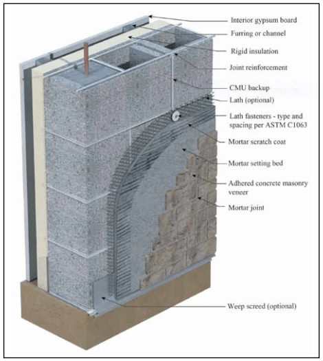
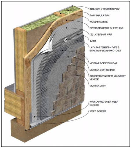
Typical installations are shown in Figures 1 and 2 for concrete masonry and wood frame applications, respectively. There are a number of key installation/inspection points that must be followed to provide a properly performing system. This TEK addresses a number of those key points.
KEY INSTALLATION/ INSPECTION POINTS
1. Substrate Preparation
Wood- and Metal-Framed Applications
According to The Engineered Wood Association’s (APA) Installation of Stucco Exterior Over Wood Structural Panel Wall Sheathing (ref. 1), when wood structural panel sheathing (plywood or oriented strand board – OSB) is used as the substrate material, it must have a ⅛ in. (3 mm) gap between the sheets on all sides to accommodate wood sheathing expansion when it gets wet. Without the gap, wood swelling will cause the adhered masonry veneer finish to crack, compromising the water resistance of the finish. This will allow water entry and degradation of the substrate, the veneer and the framing. Additionally, the wood framing should be relatively dry at the time of installation, as drying of the wet substrate causes shrinkage which could lead to cracking of the finish. Also note that the International Building Code (ref. 11) limits the deflection of wall systems to L/240 for brittle finishes.
Concrete and Concrete Masonry Walls
Manufactured stone veneer can be directly applied to surfaces of concrete and concrete masonry if they are free of dirt, waterproofing, paint, form oil, or any other substance that could inhibit the mortar bond. They must have a rough texture to ensure a mortar bond. ICRI guideline number 03732 (ref. 5) discusses Concrete Surface Profile (CSP), a standardized method to measure concrete surface roughness. An ICRI CSP equal to or greater than 2 is usually acceptable. Typically, cleaning may be done with power washing and/or mechanical methods (i.e. shot or bead blasting). If a bondable surface cannot be achieved, attach lath and a scratch coat before installing manufactured stone veneer. Do not bond manufactured stone masonry veneer to clay masonry surfaces.
Figure 1—Application of Adhered Concrete Masonry Veneer Over Concrete Masonry With Lath
2. Water Management
ASTM C1780, Standard Practice for Installation Methods for Adhered Manufactured Stone Masonry Veneer, (ref. 3) requires two separate layers of water-resistive barrier (WRB) to be installed over wood sheathing in exterior applications. The standard also requires that the two separate layers be installed in shingle fashion. Starting from the bottom of the wall, the inner layer of WRB should be installed, along with flashings, to create a drainage plane. The upper layer of the WRB should lap the top of the lower layer by a minimum of 2 in. (51 mm). The vertical joints of the WRB must be lapped a minimum of 6 in. (152 mm). Inside and outside corners must be overlapped a minimum of 16 in. (406 mm) past the corner in both directions. The WRB should be installed in accordance with the manufacturer’s recommendations and be integrated with all flashing accessories, adjacent WRBs, doors, windows, penetrations, and cladding transitions. The outer layer of WRB is intended to keep the scratch coat from contacting the inner layer of WRB and may be of a different material than the inner WRB.
Drainage Wall Systems: Drainage wall systems also are a very effective means of keeping water from penetrating to the interior and diverting it to the exterior. These systems have a minimum drainage gap of 3/16 in. (5 mm) and a maximum drainage gap of ¾ in. (19 mm). When a system of this type is used, some building codes permit the use of a single WRB.
Other checkpoints for effective water management include:
flashing at all penetrations, terminations and transitions, integrated with the WRB and water directed out of the system,
proper overhang of capping mateials, and
soft joints at dissimilar materials to accommod and soft joints at dissimilar materials to accommodate some movement and minimize incidental water penetration.
3. Proper Selection of Metal Lath by Weight and Style for Each Span and Application
ASTM C1063, Standard Specification for Installation of Lathing and Furring to Receive Interior and Exterior Portland Cement-Based Plaster (ref. 4) must be followed for properly performing manufactured stone veneer system. All lath must be self-furred or use self-furring fasteners to allow the mortar to completely fill and encase the lath.
All lath and lath accessories must be corrosion resistant, consisting of either galvanized or stainless steel materials or nonmetallic lath with a published evaluation report from an ANSI accredited evaluation service and be rated for use behind manufactured stone veneer. More detailed recommendations can be found in the Installation Guide and Detailing Options for Compliance with ASTM 1780 for Adhered Concrete Masonry Veneer (ref. 2).
Figure 2—Application of Adhered Concrete Masonry Veneer Over Wood Frame With Structural Wood Sheathing
4. Proper Installation of Metal Lath
The installation of lath should be in accordance with ASTM C1063-14a (current version), Standard Specification for Installation of Lathing and Furring to Receive Interior and Exterior Portland Cement-Based Plaster (ref. 4). Metal lath should be applied horizontally (perpendicular to framing, if present) per manufacturer’s instructions, and should over- lap a minimum of 1 in. (25 mm) at the vertical seams and a minimum of ½ in. (13 mm) at the horizontal seams. The ends of adjoining lath places should be staggered. Lath should be wrapped around inside and outside corners a minimum of 12 in. (305 mm). Lath should be fastened every 7 in. (178 mm) vertically on each stud. The spacing of studs should not exceed 16 in. (406 mm). A similar spacing should be used on concrete or masonry wall surfaces. Do not end lath at inside/outside corner framing.
If not installed in accordance with ASTM C1063, alternate lath installation practices should be in accordance with manufacturer’s instructions. Acceptable installation practices for metal lath should be evaluated in accordance with AC191, Acceptance Criteria for Metal Plaster Bases (Lath) (ref. 12).
While recommendations vary, existing codes and standards do not stipulate the orientation of the lath “cups” (keys) once installed. More important than the orientation of the lath cups is ensuring the lath is embedded within, and bonded to, the mortar scratch coat for a successful AMSV installation. Lath is considered to be embedded within the mortar scratch coat when there is a ¼ in. (6 mm) nominal thickness of mortar between the back plane of the lath and the back plane of the scratch coat for at least one-half (50%) of the surface area of the installation.
When lapping paperbacked lath, be sure that lath is against lath and paper against paper. Paper backing inserted between lath at laps will prevent the mortar from going into the second lath and won’t lock the two sheets together. This can cause cracking in the manufactured stone veneer at the lath joint.
In the summer months, paperbacked lath must be protected from the sun and extreme heat to prevent the glue that attaches the paper to the lath from melting.
5. Proper Fastening of Lath
Proper fastener spacing and penetration is critical. Corrosion resistant fasteners (ref. 4) require a minimum ¾ in. (19.1 mm) nail penetration into wood framing members, a minimum ¾ in. (19.1 mm) staple penetration into wood framing members, or minimum a ⅜ in. (9.5 mm) penetration of metal framing members. Fasteners must have heads large enough to properly engage the lath.
Note that fasteners must be anchored into the framing members and are to be spaced no more than 7 in. (178 mm) on center per ASTM C1063 (ref. 4). Wood and gypsum sheathing do not have enough holding power to fully support the lath and manufactured stone veneer. A fastener attached only to the sheathing can work loose, particularly if the sheathing becomes wet. Proper fastening will help ensure that the veneer does not become detached during high wind events.
Fastener type and size is also very important. For installation directly to wood framing members, ASTM C1063 allows for the use of 1 ½ in. (38 mm) roofing nails to horizontal framing members. Vertical applications require the use of 1-in. (25-mm) roofing nails, 1-in. (25-mm) staples with minimum ¾-in. (19-mm) crowns, or 6d common nails driven to a penetration of at least ¾ in. (19 mm) and bent over to engage at least three strands of lath.
Where welded or woven wire lath is installed, rest the wire on the fastener for best performance rather than installing the fastener above the wire.
For fastening lath to steel supports, reference is made to ASTM C954 (ref. 6) by ASTM C1063 for screw information. Per that standard, lath can be wire-tied to the member with 18-gauge tie wire. Whether wire or screws are used, the maximum allowed spacing should be maintained, and once again all fastening must be corrosion resistant and penetrate into the structural member. ASTM C954 also states that the screw shall have a minimum head size of 7/16 in. (11 mm) with either a pan or wafer head large enough to engage at least three strands of lath.
6. Clearances
The following minimum clearances are critical to the proper performance of manufactured stone veneer:
Exterior Stud Walls or Where Manufactured Stone Veneer Continues Down a CMU Foundation Wall with WRB and Lath:
a. 4 in. (102 mm) from grade/earth
b. 2 in. (51 mm) above paved surfaces such as driveways, patios, etc. This minimum can be reduced to ½ in. (13 mm) if the paved surface is a walking surface supported by the same foundation that supports the wall.
Exterior Concrete or Masonry Walls with or without Lath and Weep Screeds:
a. 2 in. (51 mm) clearance from grade or ½ in. (13 mm) from a paved surface.
7. Mortar Selection, Mixing and Application
Choose the proper mortar Type for scratch coats and pointing mortars: ASTM C270 (ref. 7) Type N or S for sitemixed or ASTM C1714 (ref. 8) Type N or S for premixed mortar. Setting mortars are the same except that ANSI A118.1 or ANSI A118.4 also may be used (refs. 9, 10)).
Mix the mortar properly and employ hot weather provisions when the ambient temperature is above 90°F (32°C) and cold weather provisions when the temperature is below 40°F (4°C).
Apply the scratch coat with sufficient material and pressure to completely encapsulate the lath with a nominal thickness of ½ in. (13 mm), ensuring that the lath is completely encapsulated with mortar. Horizontally score the surface after the scratch coat is somewhat firm.
If applying to a scratch coat on open studs, non-solid sheathing, or metal building panels, allow the scratch coat to cure 48 hours, then dampen it before applying the setting bed. The setting bed mortar can be applied directly to the scratch coat, to the back of the manufactured stone veneer units (back-buttering), or a combination of both application methods.
8. Setting Manufactured Stone Veneer Units
Dampen the unit’s bonding surface and apply enough setting bed mortar to fully cover the back of the unit with ample squeeze-out between the units.
Take care not to bump previously installed stones. If a unit is inadvertently moved after initial set has begun, it should be removed, mortar scraped off the unit and the scratch coat, and then reinstalled following the application process.
Pay attention to weather conditions and adjust installation procedures for hot or cold weather as needed.
If filled mortar joints are to be provided, add pointing mortar to fill in the joints after there is sufficient cure time of the installed units, when mild contact will not break the bond to the backup system. Tool the pointing mortar when thumbprint hard. Concave or V-groove tooling provides the best water penetration resistance. Filled mortar joints are recommended at schools and other public places as children tend to try climbing walls with unfilled joints.
Clean off remaining mortar debris on the veneer surface with a dry, soft-bristled brush. To prevent mortar smearing, DO NOT use a wet brush to treat uncured mortar joints.
9. Environmental, Chemical, Cleaning and Other Abuse
Avoid exposing manufactured stone veneer to the following as they can result in discoloring or surface damage:
de-icing chemicals, salt, or other harsh chemicals such as acid cleaners and pool chemicals,
sprinklers and roof downspouts should be positioned to prevent frequent moistening of the units, and
avoid installing in areas where the units may be kicked, scraped, or scuffed such as on stair risers.
INSPECTION CHECKLIST
For Wood or Steel Stud Wall Systems:
Minimum ⅛ in. (3 mm) gap between sheathing panels.
Minimum of two layers of a water resistive barrier (WRB) for exterior applications.
Proper and sufficient lap of WRBs.
Fasteners for lath placed into framing members with sufficient penetration.
Corrosion-resistant lath, flashing, fasteners, and accessories.
Lath cups facing up with at least ¼ in. (6 mm) space to backing.
Proper and sufficient lap of lath and no WRB between lath at laps.
Scratch coat of proper materials, proper thickness and completely encapsulating lath.
Scratch coat scored horizontally after it is somewhat firm.
For Concrete Masonry or Concrete Wall Systems:
Use lath if surfaces are not clean and free from release agents, paints and other bond breakers for bonding directly. See checklist items for lath above.
If using lath and a WRB is needed, see checklist items for WRB above.
If a scratch coat is needed if not using lath, see checklist items for scratch coat above.
For Concrete Masonry, Concrete and Stud Wall Systems:
Dampen scratch coat and units before applying setting mortar with full coverage and squeeze-out between units.
For placed units inadvertently bumped, remove stones and mortar and reinstall.
For filled joints, apply pointing mortar after setting mortar has sufficiently cured. Tool joints when pointing mortar is thumbprint hard.
Properly clean pointing mortar debris from veneer surface.
REFERENCES
Installation of Stucco Exterior Over Wood Structural Panel Wall Sheathing. The Engineered Wood Association (APA), 2006.
Installation Guide and Detailing Options for Compliance with ASTM C1780 for Adhered Manufactured Stone Veneer, 5th Concrete Masonry and Hardscapes Association, 2023.
Standard Practice for Installation Methods for Adhered Manufactured Stone Masonry Veneer, ASTM C1780-14. ASTM International, 2014.
Standard Specification for Installation of Lathing and Furring to Receive Interior and Exterior Portland Cement- Based Plaster, ASTM C1063-14a, ASTM International,
Selecting and Specifying Concrete Surface Preparation for Coatings, Sealers, and Polymer Overlays, ICRI Technical Guideline No. 03732. International Concrete Repair Institute, 2009.
Standard Specification for Steel Drill Screws for the Application of Gypsum Panel Products or Metal Plaster Bases to Steel Studs from 033 in. (0.84 mm) to 0.112 in. (2.84 mm) in Thickness, ASTM C954-11. ASTM International, 2011.
Standard Specification for Mortar for Unit Masonry, ASTM C270-14. ASTM International, 2014.
Standard Specification for Preblended Dry Mortar Mix for Unit Masonry, ASTM C1714/C1714M-13a. ASTM International, 2013.
American National Standard Specification for Standard Dry-Set Cement Mortar, 1. American National Standards Institute, 2013.
American National Standard Specification for Modified Dry-Set Cement Mortar, A118.4. American National Standards Institute, 2013.
International Building Code. International Code Council,
Acceptance Criteria for Metal Plaster Bases (Lath), AC191. ICC Evaluation Service, Inc., 2012.
Successfully sealing joints, such as control joints and around door jambs and window frames, in concrete masonry walls depends on the overall design and construction of the entire building envelope. Movement joints (also called control joints) are needed in some concrete masonry walls to accommodate drying shrinkage, thermal movements, and movements between different building components. Movement joints, joints around fenestration, doors and penetrations, and isolation joints (joints at dissimilar material interfaces) rely on joint sealants to help preserve the overall weather-tightness of the building envelope. In addition, properly sealed joints may be required to meet a specified fire resistance rating or sound transmission class.
The sealant’s primary role is to deform as the joint moves, maintaining the seal across the joint. Most joint sealants are field-applied (as opposed to preformed). For instance, a raked-out mortar joint or open movement joint may receive sealant from a gun-squeezed cartridge, typically applied over a backup material.
This TEK provides a basic overview of joint sealants, installation guidelines to help ensure longevity, and recommended maintenance procedures, based primarily on ASTM C1193, Standard Guide for Use of Joint Sealants (ref. 1) and ASTM C1472, Standard Guide for Calculating Movement and Other Effects When Establishing Sealant Joint Width (ref. 2). This TEK does not address adhesives.
For optimum performance, the sealant must be properly applied to a well-constructed joint. For example, joints that are too thick relative to the width may cause failure of even the best sealant. Detailed information on control joint design and construction is available in CMU-TEC-009-23 (ref. 3).
JOINT SEALANTS AND RELATED MATERIALS
Control joints in concrete masonry construction are classified as butt-joints, where the sealant is exposed to cyclical tension and compression as the joint expands and contracts. Therefore, control joint sealants should be able to maintain their original shape and properties under these conditions. In addition, joint sealants should be impermeable, deformable to accommodate the joint movement, and be able to adhere to concrete and masonry materials or be used with an appropriate primer. The use of primers has been reported to improve bond as well as watertightness at the joint. Because many factors influence a wall’s water penetration resistance, the reader is referred to TEK 19-02B, Design for Dry Single-Wythe Concrete Masonry Walls (ref. 4) for more complete information.
Some variables to consider when selecting a joint sealant are the sealant’s: joint movement capability (typically reported as two percentages, one for elongation and another for compression), time to set-up/cure, adhesion/bond strength to concrete masonry or other substrates, hardness, tensile strength, durability, expected life in service, ease of installation, primer requirements, application temperature range, paintability, warranty requirements, and sag-resistance. Materials that dry out rapidly and/or do not effectively bond to masonry, such as most oil-based caulks, are generally not recommended for use as concrete masonry joint sealants.
In-service conditions for the particular application must also be considered. For example, for joints that are not exposed to the weather, aesthetic factors such as available colors may be more important than the weather-resistance of the joint. Other applications may require properties such as chemical or fire resistance.
In short, no single sealant will meet the requirements of every application. The following sections briefly describe the most common materials used for concrete masonry joints.
Masonry Joint Sealants
Sealants must comply with ASTM C920-11 Standard Specification for Elastomeric Joint Sealants (ref. 6). Sealants used for concrete masonry joints and at penetrations in concrete masonry walls may be polyurethanes, polysulfides, acrylics, silicones, or even modified blends of each. These sealant materials tend to have:
high resistance to aging and weathering,
good resistance to low-temperature hardening,
moderate resistance to age-related hardening,
high resistance to indentation,
low shrinkage after installation, and
nonstaining properties.
Backup Materials
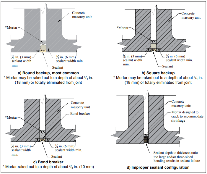
Backup materials are used to: restrict the sealant depth, support the sealant, facilitate tooling, and help resist indentation and sag. They may also serve as a bond breaker, preventing the sealant from adhering to the back of the joint. Backup materials for concrete masonry joints are commonly flexible foams, which are compressed into the joint using hand tools (see Figures 1a and 1b).
Backup materials for control joints must be compressible to accommodate masonry expansion (joint shrinkage), and must recover when the masonry shrinks (joint expands). Because the backup also needs to maintain contact with both joint faces when the joint expands, it is compressed when initially installed. Closed-cell backups should be sized 1 ¼ to 1 ⅓ the joint width, so they are compressed 25% to 30% when placed in the joint. Open-cell backups, which are less stiff than closed-cell, should be sized 1 ½ times the joint width, so they are compressed about 50% of their undisturbed width when installed.
Bond Breakers
Bond breakers prevent three-sided adhesion of the sealant (i.e. from adhering to the back of a raked joint or to the backup), allowing the sealant to freely deform in response to building movements (see Figure 1c). Because many backup materials act as bond breakers, a separate bond breaker material is not always required. When it is, polyethylene tape, butyl tape, coated papers and metal foils can be used as well as polyurethane, polyethylene and polyolefin foams. Liquid-applied bond breakers are not recommended because of the likelihood of contaminating the sealant adhesion surface.
Primers
Primers, applied to the joint surfaces prior to sealant installation, are sometimes recommended to improve the sealant’s bond strength. In addition, some primers can tolerate application to damp masonry surfaces.
Check the sealant manufacturer’s recommendations for the particular sealant under consideration to determine whether or not a primer should be used on a masonry substrate. To ensure the primer and sealant will be compatible, use the primer recommended by the sealant manufacturer for the sealant being used.
Primer is applied by brush, roller or spray, and typically must dry or cure before sealant application. The recommended elapsed time between primer application and sealant application varies with type of primer, temperature and humidity.
Figure 1—Common Sealant Configurations
JOINT SEALANT INSTALLATION
Like most materials, joint sealants should be installed in accordance with manufacturer’s instructions. Elements that are due special consideration, such as sealant depth and surface preparation are discussed in more detail below.
It is typically recommended that joint sealants not be applied during rain or snow, and that the masonry be clean and dry at installation. Installation temperature, i.e., the temperature of the masonry when the sealant is applied, may also be a consideration in some cases. Sealants installed at very low temperatures undergo compression as the wall warms up to the mean temperature, while a sealant installed at a high temperature is placed in tension at the mean temperature. For these reasons, it is desirable to have the installation temperature close to the mean annual temperature, although an in- stallation temperature range of 40° to 90°F (4.4 to 32.2°C) is generally considered acceptable for most applications, unless otherwise specified by the sealant manufacturer (ref. 6). Note that the masonry surface temperature may greatly exceed the ambient air temperature, especially on dark-colored and/or south- and southwest-facing walls in the sun.
Sealant Width and Depth
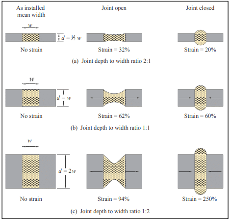
Sealant shape factor refers to the mean width versus mean depth of the sealant as installed in the joint. This ratio is important because it affects the amount of strain the sealant is exposed to as the joint moves, as well as the amount of sealant required to fill the joint (see Figure 1d). Sealants exposed to less strain can typically be expected to have a longer life, all other factors being equal. As illustrated in Figure 2, wider and shallower sealant profiles generally reduce strain and require less sealant.
In the field, sealant shape factor is controlled by varying the depth of the sealant, because the width of the joint is fixed at that point. The depth of sealant in the joint is typically controlled via the use of a backup material. Sealants that have a higher depth to width ratio tend to stretch more readily with joint movement, whereas with lower ratios the tendency is for the sealant to tear when subjected to movement. In general, for joint widths from ¼ to ½ in. (6 to 13 mm) the joint depth should be no more than the width of the joint. After the sealant is tooled, the minimum thickness of the sealant at the midpoint of the joint opening should not be less the ⅛ in. (3 mm) and the sealant adhesion dimension no less than ¼ in. (6 mm) (refs. 1, 2). The required thicknesses also should be verified with the sealant manufacturer.
Figure 2—Effect of Sealant Shape Factor on Sealant Strain
Joint Preparation
For all control joints, mortar should be raked out of the vertical joints on both sides of the panels. The mortar should be raked out at least ¾ in. (19 mm) to allow for a backup material and sealant (⅜ in. (9.5 mm) if no backing is used). This also assures a plane of weakness at the control joint. Mortar in the control joint may also be totally omitted to ensure freedom of movement.
Proper surface preparation prior to sealant installation improves bond between sealant and masonry, and minimizes adhesion failures. Follow the sealant manufacturer’s recommendations regarding cleaning and/or priming the concrete masonry surface prior to applying sealant.
Backup materials must be installed to the proper depth in the joint to control the depth of sealant. Tools for placing backer materials can help ensure correct placement. Any tools used for placement should have a smooth surface adjacent to the backup, to avoid puncturing or otherwise damaging the backup material during placement.
Applying Sealant
Sealants may be either single- or multi-component. Multi-component sealants require thorough mixing, in accordance with the manufacturer’s instructions, to ensure uniform curing and to avoid over-mixing. Once mixed, the sealant has a limited pot life, so batch sizes should be matched to what can be installed within the pot life.
Masonry joint sealants are typically installed using a common caulk gun, with a tip the same size as the width of the joint. The caulk gun should be held at an angle of about 45° to the wall face, and moved slowly and consistently. Filling joints from bottom to top helps avoid trapping air as the sealant is placed.
Immediately after the joint is filled, the sealant should be tooled to a concave shape. Tooling helps ensure intimate contact between the sealant and masonry, consolidates the sealant, provides a concave profile and improves the appearance of the joint. The hour-glass shape shifts peak stresses away from the adhesion surface and to the middle of the sealant joint during joint movement. Most sealant manufacturers recommend dry-tooling for the best results.
MAINTENANCE
Properly maintained joint sealants will help maintain the water penetration resistance of the building envelope. Sealant materials cannot be expected to have the same life as a masonry building. For this reason, the sealant condition should be inspected on a regular basis, perhaps when the facade is cleaned, and repairs made as needed. Manufacturer’s recommendations should be used as a guideline to estimate sealant life. However, sealant life will vary greatly with exposure and the quality of the initial installation.
Because joint sealant adheres better to properly prepared surfaces, the old or deteriorated sealant should be completely removed from the joint and the joint cleaned prior to reapplication. Minor repairs can be made by cutting out the defective area and reapplying sealant of the same type. Sealants can be removed using a sharp knife to sever the sealant from the masonry. Although some manufacturers recommend more aggressive cleaning methods, such as sand-blasting or grinding, care should be taken when using these methods. For more detailed information on sandblasting, see TEK 08-04A, Cleaning Concrete Masonry, (ref. 6).
Once the joint is properly prepared, sealant can be installed as described above for new construction.
REFERENCES
Standard Guide for Use of Joint Sealants, ASTM C1193-13. ASTM International, 2013.
Standard Guide for Calculating Movement and Other Effects When Establishing Sealant Joint Width, ASTM C1472-10. ASTM International, 2010.
Crack Control Strategies for Concrete Masonry Construction, CMU-TEC-009-23, Concrete Masonry & Hardscapes Association, 2023.
Design for Dry Single-Wythe Concrete Masonry Walls, TEK 19-2B, Concrete Masonry & Hardscapes Association, 2012.
Standard Specification for Elastomeric Joint Sealants, ASTM C920-11. ASTM International, 2011.
Cleaning Concrete Masonry, TEK 8-4A. National Concrete Masonry Association, 2005.
Segmental retaining walls (SRWs) are gravity retaining walls which can be classified as either: conventional (structures that resist external destabilizing forces due to retained soils solely through the self-weight and batter of the SRW units); or geosynthetic reinforced soil SRWs (composite systems consisting of SRW units in combination with a mass of reinforced soil stabilized by horizontal layers of geosynthetic reinforcement materials). Both types of SRWs use dry-stacked segmental units that are typically constructed in a running bond configuration. The majority of available SRW units are dry-cast machine-produced concrete.
Conventional SRWs are classified as either single depth or multiple depth. The maximum wall height that can be constructed using a single depth unit is directly proportional to its weight, width, unit-to-unit shear strength and batter for any given soil and site geometry conditions. The maximum height can be increased by implementing a conventional crib wall approach, using multiple depths of units to increase the weight and width of the wall.
Reinforced soil SRWs utilize geosynthetic reinforcement to enlarge the effective width and weight of the gravity mass. Geosynthetic reinforcement materials are high tensile strength polymeric sheet materials. Geosynthetic reinforcement products may be geogrids or geotextiles, although most SRW construction has used geogrids. The geosynthetic reinforcement extends through the interface between the SRW units and into the soil to create a composite gravity mass structure. This enlarged composite gravity wall system, comprised of the SRW units and the reinforced soil mass, can provide the required resistance to external forces associated with taller walls, surcharged structures or more difficult soil conditions.
Segmental retaining walls afford many advantages, including design flexibility, aesthetics, economics, ease of installation, structural performance and durability. To function as planned, SRWs must be properly designed and installed. Inspection is one means of verifying that the project is constructed as designed using the specified materials.
This Tech Note is intended to provide minimum levels of design and construction inspection for segmental retaining walls. The inspection parameters follow the Design Manual for Segmental Retaining Walls (ref. 1) design methodology. This information does not replace proper design practice, but rather is intended to provide a basic outline for field use by installers, designers and inspectors.
INSPECTION
Many masonry projects of substantial size require a quality assurance program, which includes the owner’s or designer’s efforts to require a specified level of quality and to determine the acceptability of the final construction. As part of a quality assurance program, inspection includes the actions taken to ensure that the established quality assurance program is met. As a counterpart to inspection, quality control includes the contractor’s or manufacturer’s efforts to ensure that a product’s properties achieve a specified requirement. Together, inspection and quality control comprise the bulk of the procedural requirements of a typical quality assurance program.
SRW UNIT PROPERTIES
SRW units comply with the requirements of ASTM C1372, Standard Specification for Dry-Cast Segmental Retaining Wall Units (ref. 2), which governs dimensional tolerances, finish and appearance, compressive strength, absorption, and, where applicable, freeze-thaw durability. These requirements are briefly summarized below. A more thorough discussion is included in SRW-TEC-001-15, Segmental Retaining Wall Units (ref. 3). The user should refer to the most recent edition of ASTM C1372 to ensure full compliance with the standard.
Dimensional tolerances: ±1/8 in. (3.2 mm) from the specified standard overall dimensions for width, height and length (waived for architectural surfaces).
Finish and appearance:
free of cracks or other defects that interfere with proper placement or significantly impair the strength or permanence of the construction (minor chipping excepted),
when used in exposed construction, the exposed face or faces are required to not show chips, cracks or other imperfections when viewed from at least 20 ft (6.1 m) under diffused lighting,
5% of a shipment may contain chips 1 in. (25.4 mm) or smaller, or cracks less than 0.02 in. (0.5 mm) wide and not longer than 25% of the nominal unit height,
the finished exposed surface is required to conform to an approved sample of at least four units, representing the range of texture and color permitted
Minimum net area compressive strength: 3,000 psi (20.7 MPa) for an average of three units with a minimum of 2,500 psi (17.2 MPa) for an individual unit. When higher compressive strengths are specified, the tested average net area compressive strength of three units is required to equal or exceed the specified compressive strength, and the minimum required single unit strength is:
the specified compressive strength minus 500 psi (3.4 MPa) for specified compressive strengths less than 5,000 psi (34.4 MPa), or
90% of the specified compressive strength when the specified compressive strength is 5,000 psi (34.4 MPa) or greater.
Maximum water absorption:
18 lb/ft3 (288 kg/m3) for lightweight units (< 105 pcf (1,680 kg/m3))
15 lb/ft3 (240 kg/m3) for medium weight units (105 to less than 125 pcf (1,680 to 2,000 kg/m3))
13 lb/ft3 (208 kg/m3) for normal weight units ( > 125 pcf (2,000 kg/m3 or more))
Freeze-thaw durability—In areas where repeated freezing and thawing under saturated conditions occur, freeze- thaw durability is required to be demonstrated by test or by proven field performance. When testing is required, the units are required to meet the following when tested in accordance with ASTM C 1262, Standard Test Method for Evaluating the Freeze-Thaw Durability of Manufactured Concrete Masonry Units and Related Concrete Units (ref. 4):
weight loss of each of five test specimens at the conclusion of 100 cycles < 1% of its initial weight; or
weight loss of each of four of the five test specimens at the end of 150 cycles < 1.5 % of its initial weight.
Standard Test Method for Evaluating the Freeze-Thaw Durability of Dry Cast Segmental Retaining Wall Units and Related Concrete Units, ASTM C1262. ASTM International, Inc., 2017.
International Building Code. International Code Council, 2012.
Concrete masonry is a popular building material in part because of its strength, versatility, durability, economy and resistance to fire, impact, noise and termites. To function as designed, however, concrete masonry buildings must be constructed properly.
Concrete masonry is used in projects ranging from small single story buildings to multistory loadbearing projects and is used in every building type and occupancy, including institutional, residential, commercial and manufacturing facilities. Because of the varying nature of these facilities, masonry construction continues to evolve, becoming more detailed and multifaceted. Reinforced masonry requires masons to not only lay masonry units, but to also properly place reinforcing steel and grout. As the intricacy and variety of masonry systems continues to expand, so does the need for educated and knowledgable inspectors to verify that masonry is being constructed as designed. Likewise, ensuring that the physical properties of the masonry materials comply with project specifications requires detailed knowledge of testing procedures.
Many masonry projects of substantial size requires the implementation of a quality assurance program. A quality assurance program includes the owner’s or designer’s efforts to require a specified level of quality and to determine the acceptability of the final construction. As part of a quality assurance program, inspection includes the actions taken to ensure that the established quality assurance program is met. As a counterpart to inspection, quality control includes the contractor’s or manufacturer’s efforts to ensure that the final properties of a product achieve a specified goal under a quality assurance program. Together, inspection and quality control comprise the bulk of the procedural requirements of a typical quality assurance program.
INSPECTION
Inspection is one part of a quality assurance program, which are the administrative and procedural requirements set up by the architect or engineer to assure the owner that the project is constructed in accordance with the contract documents. Inspection is one means of verifying that the project is constructed as designed using the specified materials.
Inspection assures that masonry materials and construction practices comply with the requirements of the contract documents. Inspectors, the inspection program, and inspection records should be addressed in the quality assurance program. Local municipalities may have minimum inspection requirements that augment or complement minimum code requirements to ensure the safety of the public. Additionally, the amount of inspection required depends on the owner’s needs. The architect or engineer will typically specify the degree of inspection necessary to meet the owner’s quality assurance program, local ordinances and code requirements. (See Required Levels of Inspection below.)
Concrete Masonry Inspectors
A variety of individuals may review the progress of masonry construction. The mason, general contractor, and often the architect, engineer and owner will periodically observe the progress to verify that the masonry construction is proceeding as planned. Municipal or jurisdictional building inspectors may also be required to verify that the constructed project meets local building code requirements. In addition to these individuals, special masonry inspectors are sometimes required by the local building code or by the owner through the architect or engineer.
Each of these “inspectors” tends to look at the masonry construction differently. For example, architects, owners, and masons and general contractors may focus on aesthetic aspects of the masonry, such as color of units, color and size of mortar joints, tolerances, etc. Municipal building inspectors and engineers may concentrate more on verifying structural-related items, such as proper connections, reinforcing steel size and location and connector spacing. Individuals designated as masonry inspectors also closely inspect structural-related items but may also inspect aesthetic, weatherproofing and serviceability aspects of the masonry project as outlined in the contract documents.
The following helps address the level of inspection that may be required by masonry inspectors. It can also serve as a guide for engineers, architects, contractors and building officials engaged in masonry construction or inspection.
Required Levels of Inspection
Local municipalities may have minimum inspection requirements to ensure public safety. Additionally, the amount of inspection required depends on the owner’s needs. The architect or engineer will typically specify the degree of inspection necessary to meet the owner’s quality assurance program and local code requirements.
How long an inspector should be on a job site and what should be inspected has, however, been a source of confusion in many areas of the country. To clarify how much inspection should be required on masonry projects, Specification for Masonry Structures (ref. 1) includes detailed inspection guidelines that provide an excellent basis for the degree of inspection that should be provided on masonry projects.
The 2003 International Building Code (IBC) (ref. 2) Section 1704.5 inspection requirements are virtually identical to those in Specification for Masonry Structures. The corresponding designations are:
IBC special inspection Level 1 requirements correspond to Specification for Masonry Structures Level B.
IBC special inspection Level 2 requirements correspond to Specification for Masonry Structures Level C.
Although there is no special inspection requirement corresponding to Specification for Masonry Structures Level A, this basic requirement is covered in IBC section 109.
In addition, in the 2002 edition of Specification for Masonry Structures the three levels of quality assurance were designated Levels 1, 2 and 3, which were replaced by Levels A, B and C, respectively, in the 2005 edition. This change in nomenclature is wholly editorial and does not affect the requirements specified for each level.
Three levels of inspection are defined within Specification for Masonry Structures:
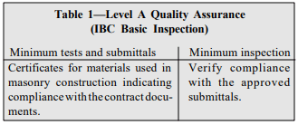
Level A (IBC Basic) – These requirements are the least stringent, requiring verification that the masonry construction complies with the plans and specifications (see Table 1). This level of inspection can only be applied to empirically designed masonry, glass unit masonry and masonry veneer used in facilities defined as nonessential by the building code. When masonry is designed by engineered methods or is part of an essential facility, Level B or C inspection is required.
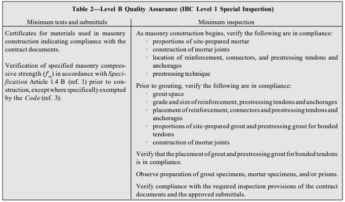
Level B (IBC Level 1) – These requirements provide a periodic-type inspection for engineered masonry used in nonessential facilities (as defined in the building code) and for empirically designed masonry, glass unit masonry and masonry veneer used in essential facilities. Key inspection items include assurance that required reinforcement, anchors, ties and connectors are in place and that appropriate grouting procedures are used (see Table 2).
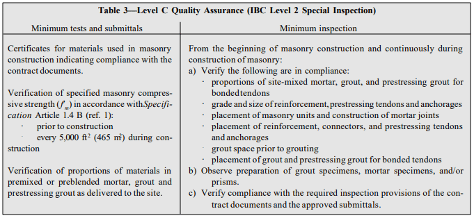
Level C (IBC Level 2) – The most comprehensive inspection procedures are required for essential facilities (as defined in the building code) that are designed by engineered design methods (see Table 3). Items inspected under a Level C quality assurance program are similar to those of Level B, with the added requirement that inspection be continuous during all phases of masonry construction.
These inspection levels are minimum criteria and may be increased when deemed necessary by the owner or designer. In this case, the contract documents must indicate the inspection level and tests that are required to assure that the masonry work conforms with the project requirements. Due to their relative importance or potential hazard, more significant inspection and quality assurance measures are required for essential facilities.
Table 1—Level A Quality Assurance (IBC Basic Inspection)
Table 2—Level B Quality Assurance (IBC Level 1 Special Inspection)
Table 3—Level C Quality Assurance (IBC Level 2 Special Inspection)
Responsibilities and Qualifications of Masonry Inspectors
Proper construction techniques are essential for a building to function as designed. Unfortunately, buildings are sometimes poorly constructed because of oversight, miscommunication, or occasionally because of unscrupulous behavior. Accordingly, inspection of the construction process can be vital to the success of a project.
An inspector’s main duty is to observe the construction to verify that the materials and completed project are, to the best of the inspector’s knowledge, in conformance wit h the contract documents and applicable building code. The inspector is not required to determine the adequacy of either the design or application of products and cannot revoke or modify any requirement nor accept or reject any portion of the work. To function effectively, the inspector must be familiar with proper construction techniques and materials, with the requirements of the local building codes, Building Code Requirements for Masonry Structures (ref. 3) and Specification for Masonry Structures. Although not required by Specification for Masonry Structures or the International Building Code, inspectors may be qualified or certified under nationally recognized education programs offered through such organizations as the International Code Council. Completion of such a program may be required by a local jurisdiction or by a building official.
Although vague, Section 1704.1 of the 2003 International Building Code provides general guidance on the minimum qualifications for inspectors, as follows:
“The special inspector shall be a qualified person who shall demonstrate competence, to the satisfaction of the building official, for inspection of the particular type of construction or operation requiring special inspection.”
The nonspecific nature of this code provision has been a source of confusion on various construction projects due to the wide variety of interpretations of a ‘qualified person.’ Some equate qualification with a nationally recognized certification, while others have allowed a noncertified individual with sufficient experience to serve as an inspector.
As a minimum, however, a masonry inspector must be familiar with masonry construction and be able to read plans and specifications effectively in order to judge whether the construction is in conformance with the contract documents. As part of this task, an inspector should always review the contract documents thoroughly before construction begins.
Inspectors must keep complete and thorough records of observations regarding the construction process. An effective way to accomplish this is by keeping a daily log when the inspector visits the project. Items such as the date, weather, temperature, work in progress (location and what was accomplished), meetings (attendees and topics of discussion), as well as overall observations and test results should be recorded in a neat, orderly manner since these notes may be needed later.
At the completion of the project or at predetermined stages of construction, inspectors must submit a signed report stating whether the construction requiring inspection was, to the best of the inspector’s knowledge, in conformance with the contract documents and applicable workmanship standards. Specific services and duties required by an inspection agency are outlined in Article 1.6 B of Specification for Masonry Structures.
TESTING AND QUALITY CONTROL
Material testing may be necessary either before, during or after the construction of a building. For example, preconstruction testing may be requested to verify compliance of materials with the contract documents and is typically the responsibility of the contractor or producer of the product. Testing during construction, as part of the owner’s quality assurance program, may also be required to ensure that materials supplied throughout the construction process comply with the contract documents. These tests are the owner’s responsibility. Additionally, testing may be necessary to determine the in-place condition of the building materials after the building is complete or during the building’s life.
Standards for sampling and testing concrete masonry materials and assemblages are developed by the technical committees of ASTM International in accordance with consensus procedures. These standards reflect the expertise of researchers, concrete masonry manufacturers, designers, contractors and others with an interest in quality standards for masonry.
Specific testing procedures for concrete masonry units and related materials are covered in detail in references 4 through 8.
REFERENCES
Specification for Masonry Structures, ACI 530.1-05/ASCE 6-05/TMS 602-05. Reported by the Masonry Standards Joint Committee, 2005.
2003 International Building Code. International Code Council, 2003.
Building Code Requirements for Masonry Structures, ACI 530-05/ASCE 5-05/TMS 402-05. Reported by the Masonry Standards Joint Committee, 2005.
Evaluating the Compressive Strength of CM based on 2012IBC/2011 MSJC, TEK 18-01B, Concrete Masonry & Hardscapes Association, 2011.
Sampling and Testing Concrete Masonry Units, TEK 1802C, Concrete Masonry & Hardscapes Association, 2014.
On all construction projects, including those involving segmental retaining walls (SRWs), it is the owner’s responsibility to achieve coordination between construction and design professionals that ensures all required design, engineering analysis, and inspection is provided. In many cases, a design professional such as a site civil engineer or an architect acts as the owner’s representative. In either case, the owner or owner’s representative should ensure that the engineering design professionals’ scope of work, roles and responsibilities are clearly defined so that there is no ambiguity regarding responsibility for investigation, analysis and design, and that all required testing is performed.
The roles outlined in this TEK are typical industry roles for various engineering disciplines. SRW design and construction should generally follow these traditional roles. However, these roles may vary from project to project, depending on the contractual obligations of each consultant. For example, for simpler projects, such as residential landscapes, one design professional may take on the responsibility of several roles, if acceptable to local building code requirements.
For tall or complex walls and for commercial projects, each of these roles is likely to be provided by separate firms, each with expertise in a particular discipline. The discussion in this Tech Note is generally oriented towards projects where several design professionals are contracted.
Reinforced SRWs, because of their nature as composite soil structures, may have unique design and inspection considerations for the site civil engineer, the geotechnical engineer, and the independent testing agency. These considerations are discussed in further detail in the following sections.
Detailed guidance on SRW design, construction and inspection can be found in references 1 through 3.
Figure 1—Reinforced Segmental Retaining Wall System Components
OVERVIEW OF ROLES
The owner/developer, or a designated representative, is ultimately responsible for ensuring that all applicable requirements of governing authorities for the permitting, design, construction and safety on the project are addressed. The owner or owners’ representative should ensure that the types of retaining walls specified are appropriate for the site conditions and ensure the wall alignment fits within the site’s space limitations. It is the owner’s or owner’s representative’s responsibility to contract an engineer to provide site civil engineering including site layout, drainage and grading. The owner must also ensure that a geotechnical engineer and testing agency are contracted to provide all necessary and required soils exploration, analysis and earthwork inspection for the entire project, including in the vicinity of the SRWs, just as they do in the vicinity of building structures. The owner or owner’s representative must also ensure that a qualified wall design engineer provides an SRW structural design.
The most straightforward means for the owner or owner’s representative to ensure all engineering roles are well-defined is for the SRW design engineer’s assigned roles to be the same as those traditionally given to a structural engineer designing a cast-in-place concrete retaining wall, and for the other design professionals, such as site civil and geotechnical engineers, to also provide the same roles and services as they would for a cast-in-place retaining wall.
Table 1 contains an itemized list of the suggested roles for each professional discipline for larger walls and commercial projects involving SRWs. A more thorough explanation of the site civil engineer’s, geotechnical engineer’s and SRW engineer’s roles, and construction observation and testing roles is provided in the following sections. The actual responsibilities for each discipline should be contractually based.
Table 1—Suggested Roles for a Segmental Retaining Wall Project
SITE CIVIL ENGINEER SUGGESTED ROLES OVERVIEW
It is suggested that the site civil engineer be contracted for all traditional site civil duties, including the design of surface drainage, storm drainage collection structures, utility layout, erosion control and scour protection. The site civil engineer is also typically responsible for site layout and grading plans, including slopes and retaining wall locations. The site civil engineer should, in consultation with the geotechnical engineer, ensure that all planned grades, including those at the top and bottom of SRWs, do not exceed the stable slope angles and do not cause surface drainage or erosion problems.
The site civil engineer should also plan the wall alignment so that the SRW structure does not encroach on any easements. In addition, the site civil engineer should be responsible for any other issues related to the wall location, such as proximity to property lines, utilities, watersheds, wetlands, or any other easements. In some cases, the site civil engineer may also act as the SRW Design Engineer and take on suggested roles for the SRW Engineer discussed below.
The site civil engineer should evaluate and design for any hydrologic issues and structures such as: culverts, open channels, detention/retention ponds, scour and erosion control details, as well as defining high water levels, flow volumes, flood areas and scour depths. The site civil engineer should provide any pertinent hydrologic data that may affect the SRW to the SRW engineer.
Often, when not designing the SRW in-house, the site civil engineer specifies the engineering design of SRWs to be part of the SRW construction contract (a design/build bid). While a common practice, this type of bid can place the SRW engineer in a different position than other project engineers. Unlike other engineers working directly for the owner, the SRW engineer in this design/build case is often working directly for a contractor, who is often a subcontractor to other contractors. This can cause design coordination issues because the SRW engineer may not be included in project discussions with other engineers, such as pre-construction meetings. Therefore, it is suggested that the site civil first determine if it is appropriate to have the SRW engineering specified as part of the wall construction contract. For some more complicated projects, it may be preferable to have the SRW design engineer perform the design prior to bidding the construction rather than as part of a design/build bid. If the site civil engineer chooses to specify the SRW design as part of the construction bid, it is recommended that the site civil engineer ensure that the SRW design engineer is involved in any required design and construction observation services before and during construction, similar to the way geotechnical engineers are often contracted for their services during construction.
GEOTECHNICAL ENGINEER SUGGESTED ROLES OVERVIEW
The geotechnical engineer should typically be contracted to provide the same engineering roles in the vicinity of the SRW as they do for all other structures on site. The geotechnical engineer’s typical roles are the investigation, analysis and testing of the site soil materials and groundwater conditions. Just as geotechnical engineers traditionally provide bearing capacity, settlement estimates and slope stability analysis for building structures, it is suggested they do the same for SRWs. The geotechnical engineer’s role should include providing soil properties such as soil shear strength parameters, ground water elevation, seismic conditions, and bearing capacities to the SRW engineer.
Responsibility for slope stability evaluation around an SRW can be a source of confusion, because the SRW engineer can often address slope stability issues near a geosynthetic-reinforced SRW by modifying the geosynthetic reinforcement layout. Thus, the SRW engineer is sometimes requested to evaluate and design for slope stability by the civil engineer’s specifications. However, involving the SRW engineer in addressing slope stability should not remove ultimate global/slope stability responsibility from the geotechnical engineer.
It is therefore suggested that, regardless of the SRW engineer’s involvement, the geotechnical engineer be contracted to have the ultimate responsibility for the site’s slope stability, including: determining when and where global stability analyses are required, determining the appropriate soils and groundwater properties to be used for the analyses, and ensuring that all required failure planes are analyzed. While the geotechnical engineer may need to coordinate with the SRW engineer for evaluating potential failure planes that pass through the reinforced soil (compound failures), the geotechnical engineer has the primary responsibility for these analyses.
When the geotechnical consultant is retained to provide construction observation and soils testing for a project, the contract should include inspection and testing of SRW earthwork along with all other earthwork on site. See TEC-008-12, Inspection Guide for Segmental Retaining Walls (ref. 3) for further discussion of inspection roles.
While geotechnical engineers should be contracted for the same traditional roles regarding SRWs as for other structures, the soils engineering for SRWs may require some slightly different methods of analysis compared to evaluating soils below rigid structures on spread footings. Design guidelines for SRWs are provided in Reference 1.
SRW DESIGN ENGINEER SUGGESTED ROLES OVERVIEW
As noted previously, the SRW design engineer should serve the same roles for SRWs as a structural engineer would for the design of a cast-in-place concrete retaining wall. In some cases, the site civil engineering firm may also act as the SRW engineer, while in others, the SRW design engineer will be a separate firm. The SRW design engineer should design a stable SRW, given the specified wall geometry and site conditions provided by the site civil and geotechnical engineers. The SRW engineer’s duties typically include determining the SRW’s maximum stable unreinforced height and providing a geosynthetic reinforcement layout design when required.
The SRW design engineer is typically responsible for preparing the SRW construction drawings, and for determining the internal stability, facial stability of the SRW units, internal drainage of the SRW (both at the face of the wall and at the rear of the reinforced soil mass, if required), external stability (sliding and overturning), and internal compound stability.
The SRW designer engineer’s output generally consists of specifications of wall components, a wall elevation detail, typical cross sections, details for any required drainage materials within or just behind the wall system, and details for how to incorporate any other structures (utilities, pipe penetrations, posts, etc.), if feasible, within the reinforced zone and wall face.
The SRW design engineer should typically not assume any duties typically relegated to the geotechnical engineer elsewhere on site. While an SRW engineer may be asked to participate in addressing the slope stability immediately around the SRW or foundation improvements in the soil below an SRW, it is recommended that the geotechnical engineer be clearly contracted to have ultimate responsibility for all slope stability and bearing capacity/settlement concerns on site, including those below and around SRWs.
It is appropriate that the SRW engineer be contracted to provide services during construction, especially on larger projects, but it is recommended that these not be included in a design/build contract for the wall construction. Time lag between design and construction can make it impractical to expect the designer to be available for services during construction and, given the often unpredictable extent and timing of construction, it is inappropriate to have services during construction be in a lump-sum design/build contract. Rather, it is suggested that the SRW engineer be hired under a separate contract directly with the owner or owner’s representative to provide services during construction. These services may include preconstruction correspondences and meetings, review of materials submittals, review of earthwork testing performed by the geotechnical engineer, and review of the wall contractor’s building practices.
CONSTRUCTION OBSERVATION AND TESTING SUGGESTED ROLES OVERVIEW
The soil in the reinforced zone should be checked to ensure it meets specifications; just as concrete and steel are inspected in a cast-in-place concrete retaining wall.
The wall contractor is responsible for quality control of the wall installation: performing necessary observation and testing to verify that the work performed meets minimum standards.
It is the owner’s or owner’s representative’s responsibility to perform quality assurance: auditing and verifying that the quality control program is being performed properly.
Just as is done for building structures and cast-in-place concrete retaining walls, foundation and retained soils should be evaluated for consistency with the soil properties used in the design. Generally, the geotechnical engineer evaluates the onsite soil conditions and performs earthwork testing. It is suggested that the geotechnical engineer perform any field and laboratory testing they deem required to verify soil conditions. The geotechnical engineer should confer with the SRW engineer regarding the reinforced soil specifications and provide the SRW engineer with the fill soil test results. The geotechnical engineer should also determine the frequency of tests required to ensure that compaction of the SRW reinforced fill meets the project specifications.
OWNER SUGGESTED ROLES OVERVIEW
Segmental retaining walls are designed to provide a long life with little to no maintenance required. After the SRW installation is complete, some very basic maintenance will help maximize the SRW project’s beauty and durability.
The most basic maintenance task is a periodic visual assessment of the SRW units and overall wall. If coatings have been applied to the wall, the need for re-coating should be assessed based on the coating manufacturer’s recommendations and the exposure conditions of the wall. Table 2 lists regular inspection tasks that can be performed on SRWs and their suggested frequency.
Periodic cleaning of SRWs may be desired to maintain the wall’s aesthetics. Cleaning recommendations for SRWs are essentially the same as those for other concrete masonry walls. The reader is referred to: TEK 8-04A, Cleaning Concrete Masonry; TEK 08-02A, Removal of Stains from Concrete Masonry; and TEK 08-03A, Control and Removal of Efflorescence (refs. 5, 6, 7), for more detailed guidance.
In addition to maintenance and cleaning, the owner is also responsible for ensuring that subsequent digging or trenching, such as for landscaping, does not impact the SRW installation. During any excavation, care should be taken to leave a zone of undisturbed soil behind the segmental retaining wall. Particular care should be taken to ensure that excavation does not damage, cut or remove the geosynthetic soil reinforcement, if present. For this reason, the owner should maintain a record of the installation, including the locations of geosynthetic reinforcement.
Once established, tree roots do not typically damage an SRW. The roots will typically not damage the wall face from behind because the drainage aggregate behind the SRW face does not support root growth. In fact, the root system can act as additional soil reinforcement, helping to further stabilize the soil. When newly planted, trees and other large vegetation should be adequately supported to prevent them from toppling and potentially damaging the SRW.
Table 2—Example SRW Maintenance Schedule (ref. 4)
REFERENCES
Design Manual for Segmental Retaining Walls, Third Edition, SRW-MAN-001-10, Concrete Masonry & Hardscapes Association, 2010.
Communities across the nation rely on concrete masonry for their prisons and detention centers. In addition to its strength and durability, the layout of concrete masonry walls and cells can be cost-effectively tailored to meet the facility’s needs. Concrete masonry is a proven product for correctional facilities, providing secure construction with a minimum of long-term maintenance.
Concrete masonry walls designed as security barriers are most often fully grouted and reinforced. Typically, vertical grouted cells with steel reinforcing in every cell are provided, although reinforced horizontal bond beams may also be specified. This type of construction is found in prisons, secure facilities or other areas where the integrity of the building envelope or wall partition is vital to secure an area.
Recent testing (refs. 1, 2) confirms the impact resistance of concrete masonry construction, and quantifies the performance of various concrete masonry wall systems.
IMPACT TESTING
Standard Test Methods for Physical Assault on Fixed Barriers for Detention and Correctional Facilities (ref. 3) is being developed to help quantify levels of security for walls designed to incarcerate inmates in detention and correctional institutions. The standard is intended to help ensure that detention security walls perform at or above minimum acceptable levels to: control passage of unauthorized or secure areas, to confine inmates, to delay and frustrate escape attempts and to resist vandalism.
The test method is intended to closely simulate a sustained battering ram style attack, using devices such as benches, bunks or tables. It addresses only those threats which would be anticipated based on the limited weapons, tools and resources available to inmates within detention and correctional facilities.
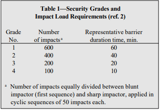
The draft security wall standard includes provisions to test monolithic wall panels as well as wall panels with simulated window openings. The standard assigns various security grades for fixed barriers based on the wall’s ability to withstand the simulated attack (see Table 1). Attack is simulated via a series of impacts from a pendulum testing ram apparatus. The testing ram is fitted with two heads: a blunt impactor to simulate a sledge hammer, and a sharp impactor simulating a fireman’s axe. The testing protocol calls for blows from both the blunt and sharp impactors, applied in sequences of 50 blows each.
Failure of a wall assembly is defined as an opening through the wall which allows a 5 in. x 8 in. x 8 in. (127 x 203 x 203 mm) rigid rectangular box to be passed through the wall with no more than 10 lb (44.5 N) of force.
The draft standard also assigns a representative barrier duration time, based on an historical testing observation that sustained manpower can deliver 400 blows of 200 ft-lb (271.2 J) each in 45 minutes. The element of time assigned to the various security grades is adjusted to achieve more manageable time periods than actual calculations provide. The amount of time is estimated and is offered solely as supplementary design information to assist the user in matching security grades with the attack resistance times and staff response times required for each barrier in the facility.
Table 1—Security Grades and Impact Load Requirements (ref. 2)
CONCRETE MASONRY SECURITY GRADES
Using the test method described above, 8-in. (203- mm) concrete masonry walls, with and without window openings, have been shown to meet the highest security rating, Grade 1, with a representative barrier duration time of at least 60 minutes.
Typical Federal Bureau of Prisons masonry wall systems include: Type A, 8-in. (203-mm) normal weight concrete masonry with No. 4 (M #13) reinforcement at 8 in. (203 mm) on center both vertically and horizontally; and Type B, 8-in. (203-mm) normal weight concrete masonry with No. 4 (M #13) reinforcement at 8 in. (203 mm) on center vertically. Note that although both of these wall designs call for normal weight concrete masonry units, test results on a wall constructed using lightweight units (ref. 1) exceed the minimum requirements for a Grade 1 barrier, as do those for normal weight units.
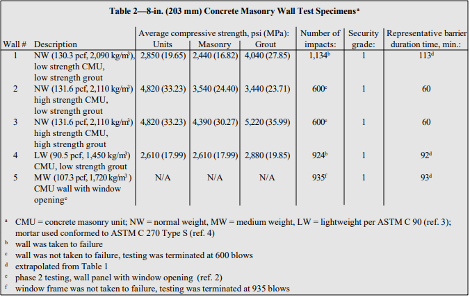
Test Results
Five concrete masonry wall assemblies were tested (refs. 1, 2), and are described in Table 2. All five concrete masonry walls were able to withstand 600 blows and therefore achieve the Grade 1 rating in accordance with the draft ASTM standard for security walls. Additionally, the back side of each wall assembly was monitored after each sequence of 50 blows and no penetration or damage, including minor cracks, was observed during the 600 blows.
Subsequent to this testing, two of the wall assemblies were taken to failure. That is, walls #1 and #4 were subject to the blunt and sharp impactors in cycles of 50 blows apiece until the forcible breach defined in the draft security wall standard was observed. Wall #1 failed at 1,134 blows. Extrapolating the criteria in the draft ASTM standard, this corresponds to a rating of 1.8 hours. Wall #4 failed at 924 blows, which corresponds to a security rating of approximately 1.5 hours.
Table 2—8-in. (203 mm) Concrete Masonry Wall Test Specimens
Test Specimens
All walls were constructed using 8 in. (203 mm) thick concrete masonry units with grout and one No. 4 (M #13) vertical reinforcing bar in each cell. Typical security wall construction provides stiffness at both the top and bottom of the wall through interconnection with the foundations below and the floor slab above. Rather than constructing individual flat wall panels with both a foundation below and a slab above as well as end returns (simulating stiffness provided by wall intersections), two four-sided closed cells were constructed: one for the wall panels without openings and one for the wall panels with simulated window openings. The walls were grouted into a reinforced concrete foundation and a reinforced concrete cap was used to fix the tops of the concrete masonry walls. Figure 1 shows the test panel configuration for the walls without window openings.
The four wall assemblies without openings differed in the types of concrete masonry units used and/or the grout strength used. These differences are fully described in Table 2. Three of the walls used normal weight concrete masonry units (with a concrete density of approximately 130 pcf (2,082 kg/m³)), and the fourth used lightweight units (with a concrete density of 90.5 pcf (1,450 kg/m³)).
For testing the walls without openings, the impacts were applied to the intersection of a bed and head joint at the midpoint of the wall. This location was chosen to be the predicted weak point of the wall assembly. Therefore, using the testing ram, a series of strikes were set against the target area and each strike was within ± 2 in. (51 mm) horizontally and vertically from the designated target area.
For the panel with the typical prison window frame (ref. 2), the window frame was manufactured to meet Guide Specifications for Detention Security Hollow Metal Doors and Frames, ANSI/HMMA– 863 (ref. 6) as required by the draft ASTM security wall standard. The nominal dimensions of the frame were 14 in. wide, 38 in. high, with a jamb width of 8 ¾ in (356 x 965 x 222 mm). The window frame was constructed of ¼ in. (6.4 mm) thick steel. The frame came equipped with masonry anchors that accommodated the vertical reinforcing bars in the masonry and then attached to the window frame. Once installed, the hollow area at the jamb was grouted solid. The intent of this impact testing is to check the integrity of the frame-to-masonry connection by striking at a corner of the window frame.
Figure 1—Prison Impact Test Wall Configuration
SPECIALIZED CONCRETE MASONRY UNITS FOR PRISON WALL CONSTRUCTION
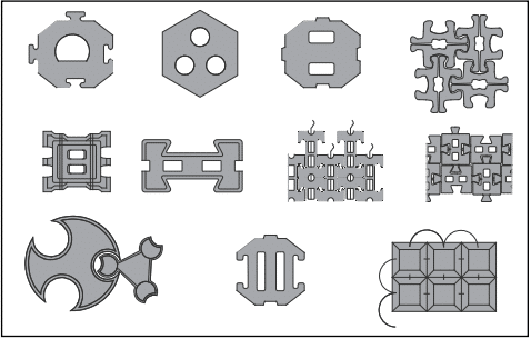
Concrete masonry units are manufactured in many different shapes and sizes. Although conventional concrete masonry units are often used for prison construction, some specialized units may also be available which are particularly well-suited for prison construction, such as those shown in Figure 2. Shapes intended to easily accommodate vertical and/or horizontal reinforcement include open-ended units and bond beam units. Open-ended units, such as the A- and H- shaped units shown in Figure 2a, allow the units to be threaded around vertical reinforcing bars. This eliminates the need to lift units over the top of the reinforcing bar, or to thread the reinforcement through the masonry cores after the wall is constructed. Horizontal reinforcement and bond beams in concrete masonry walls can be accommodated either by sawcutting out of a standard unit or by using bond beam units (Figure 2b). Bond beam units are either manufactured with reduced webs or with “knock-out” webs, which are removed prior to placement in the wall. Horizontal bond beam reinforcement is easily accommodated in these units.
Figures 2c and 2d show special Y-shaped and corner units developed specifically for prison construction. The Y-shaped units (with one 90° angle and two 135° angles) were developed to allow one corner of a rectangular prison cell to be used as a triangular chase for plumbing, electrical and HVAC service. By truncating the cell corner in this way, all repairs and maintenance can be accomplished without tradesmen ever having to enter the cell, thus reducing additional security risks. The Y-shaped and corner units allow this construction, as well as construction of nonrectangular cells, without creating continuous vertical joints in the wall.
Figure 2—Concrete Masonry Units for Prison Construction
REFERENCES
Prison Wall Impact Investigation. National Concrete Masonry Association, May 2001.
Prison Wall Impact Investigation, Phase 2 . National Concrete Masonry Association, December 2002.
Revision No. 12 Standard Test Methods for Physical Assault on Fixed Barriers for Detention and Correctional Facilities. ASTM International, 2001.
Standard Specification for Loadbearing Concrete Masonry Units, C 90-02. ASTM International, 2002.
Standard Specification for Mortar for Unit Masonry, C 270-02. ASTM International, 2002.
Guide Specifications for Detention Security Hollow Metal Doors and Frames, ANSI/HMMA– 863-98. Hollow Metal Manufacturers Association, 1998.
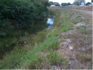
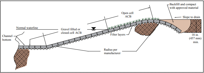
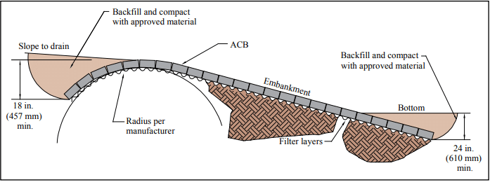
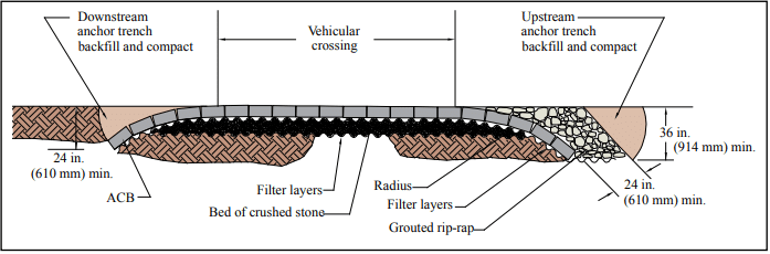
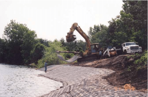
An articulating concrete block (ACB) system is a matrix of individual concrete blocks placed together to form an erosion-resistant overlay with specific hydraulic performance characteristics. The system includes a filter layer underlay that allows infiltration and exfiltration to occur while providing particle retention of the soil subgrade. The filter layer may be comprised of a geotextile or properly graded aggregate or both. The blocks within the matrix must be dense and durable while providing a matrix that is flexible and porous.
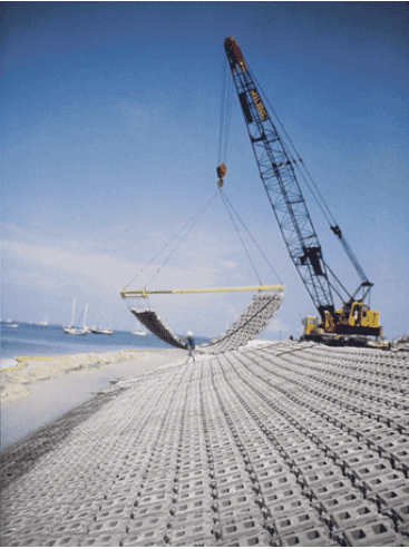
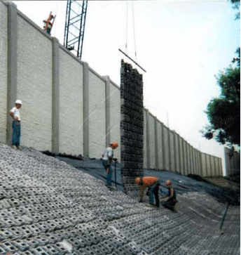
Articulating concrete block systems are used to provide protection to underlying soil materials. The term “articulating” implies the ability of individual blocks of the system to conform to changes in subgrade while remaining interlocked or otherwise restrained by virtue of the block geometric interlock and/or additional system components such as cables, ropes, geotextiles, or geogrids. The interlocking property provided by the special shapes of ACBs also allows for expansion and contraction. Long-term durability and sustainability relies on an appropriate engineered design based on site-specific hydrological and geotechnical conditions. They are either hand-placed or installed as pre-assembled mats on top of a filter layer on prepared subgrade, and act as a soil revetment.
Articulating concrete blocks (ACBs) are an effective erosion control system used to solve a wide variety of erosion problems:
drainage channels
wildlife habitat
river fronts
bridge abutments/piers
coastal shorelines
dikes and levees
pipeline protection
spillways
boat ramps
retention basins
lake shorelines
overflow channels
low water crossings
dam overtopping
The systems are easy to install, simple to produce, and environmentally friendly. ACB systems are often used as an alternative to cast-in-place concrete bulkheads and slope paving, gabions, soil cement, roller compacted concrete, or rock riprap. ACBs can also be used as grid pavers. However, grid pavers manufactured according to ASTM C1319, Standard Specification for Concrete Grid Paving Units (ref. 7), are not considered ACBs.
Articulating concrete blocks are produced in accordance with ASTM D6684, Standard Specification for Materials and Manufacture of Articulating Concrete Block (ACB) Revetment Systems (ref. 3). They can be made in a variety of shapes and thicknesses, and may even be colored according to preference. ACBs have excellent resistance to hydraulic shear and overtopping conditions. Design resources for ACBs include the Design Manual for Articulating Concrete Block and ACB Design Spreadsheet (refs. 2, 8).
Stream Channelization, Before and After ACB Installation
ENVIRONMENTAL BENEFITS
One of the environmental benefits of ACB erosion systems is that vertical cores and spaces can be incorporated throughout the system, which allows vegetation growth. Properly selected plant species can almost completely cover the entire hard surface of the ACBs, allowing them to blend in with the natural look of the project as well as water purification by absorbing nutrients and breaking down other pollutants. During peak storm events, the ACB layer beneath the vegetation will protect the soil from erosion. The ability to support the ecosystem’s habitat is a major advantage of ACB systems over other erosion control methods. Additional advantages of ACB systems are:
serviceability
aesthetics
pedestrian safety
sustainability
cost effectiveness
flexibility
The permeability of ACBs allows their use to preserve natural drainage and treatment systems. ACBs installed on filter media are pervious surfaces that reduce water runoff and flooding risks, improve water quality, reduce pollutants, recharge aquifers and prevent erosion. These environmental characteristics permit the use of ACBs on sustainable developments to preserve or improve existing sites and can be applicable to credits in some green building rating systems, such as LEEDTM, which is discussed in more detail below.
ACBs installed over drainage layers can also be used in a Best Management Practices (BMP) plan to preserve or improve existing sites, or in new developments. The system installed over a drainage layer preserves the natural drainage and treatment systems of the soil, reducing water runoff and flooding risks, improving water quality, reducing pollutants, recharging aquifers, and preventing erosion. Research on permeable pavers that are installed in a similar manner to ACBs (block over a gravel drainage layer) has also shown a promotion of aerobic biodegradation of hydrocarbons and reduction of nutrients (refs. 11, 12). When vegetated, they can also generate habitat. These qualities make ACBs a great solution for use in sustainable projects where water quantity and quality control are extremely important.
LEED Certification
ACBs can also make a significant contribution to project certification under Leader in Energy and Environmental Design (LEED) registered projects. Under LEED v3 for New Construction (ref. 9), ACB products can help attain points toward certification in the following categories: Sustainable Sites, Materials & Resources, and potentially Innovation in Design and Regional Priority Credits. These are briefly discussed below, based on LEED v3 for New Construction. Other versions of LEED may have different credit numbers, or slightly different criteria. For more detailed information on ACB’s potential contributions towards LEED credits, see TEK 06-09C, Concrete Masonry and Hardscape Products in LEED 2009 (ref. 10).
Sustainable Sites: ACBs can help capture up to 5 credits of the 26 possible in the following areas:
Prerequisite—The project is required to reduce the pollution generated during construction. ACBs can contribute to preventing erosion, reducing dust when working as drivable surfaces, and constructing sediment basins with the added support for vegetation growth that increases water quality.
Credit 5.1, Protect or Restore Habitat—ACBs can be used to restore erosion-prone areas by retaining soil and promoting plant growth.
Credit 5.2, Maximize Open Spaces—Ponds constructed with ACBs may count as open space as long as they are vegetated and meet the maximum 1:4 (vertical : horizontal) side slope limit.
Credit 6.1, Storm Design: Quantity Control—Using ACBs can reduce a site’s impermeable hardscaping for slope stability and erosion control, allowing stormwater to percolate into the ground and reducing runoff. In addition, receiving channels protected with ACBs can reduce erosion, reduce impervious surfaces and, when planted, contribute to the overall aesthetics and ecology.
Credit 6.2, Storm Design: Quality Control—ACBs can also be used to reduce the amount of stormwater that requires treatment. As discussed above under Environmental Benefits, ACBs on gravel filters have been shown to improve runoff quality.
Credit 7.1, Heat Island Effect: Non Roof—Open grid ACBs (at least 50% pervious) or with a Solar Reflectance Index (SRI) of at least 29 can be used in lieu of traditional concrete or asphalt to reduce the urban heat island effect.
Materials and Resources: ACBs can contribute towards 8 of the 14 possible credits in the following areas:
Credit 2, Construction Waste Management— Damaged concrete products can be redirected to the manufacturing process for recycling and unused products can be reused on another project.
Credit 3, Material Reuse—ACBs can potentially be salvaged from one project and reused in another.
Credit 4, Recycled Content—Concrete products, including ACBs, can be manufactured using recycled materials that have been diverted from the waste stream.
Credit 5, Regional Materials—Concrete hardscape products are usually available close to the point-of-use and are manufactured with local materials.
Innovation in Design: Projects can earn Innovation in Design credits by exceeding the LEED credit requirements, or by addressing innovative environmental strategies not specifically addressed in LEED, such as the life cycle environmental impact of the materials used.
Regional Priority Credits: Up to 4 LEED credits can be earned through Regional Priority Credits, which are designed to encourage designers to focus on specific regional needs. The credits are classified by zip code and designers have the option to excel in aspects of the project that are priorities in their region. ACBs could contribute to attain higher percentages on all the credits mentioned above to qualify for extra points.
ACB UNITS
ACB units complying with ASTM D6684, Standard Specification for Materials and Manufacture of Articulating Concrete Block (ACB) Revetment Systems (ref. 3), are produced as dry-cast (in a block machine) or wet-cast (with concrete and molds). Sampling and testing of dry-cast ACB units are performed in accordance with ASTM C140, Standard Test Method for Sampling and Testing Concrete Masonry Units and Related Units (ref. 6), for conformance with the requirements in Table 1. Sampling and testing of wet-cast units is performed in accordance with ASTM C39, Standard Test Method for Compressive Strength of Cylindrical Concrete Specimens and ASTM C42, Standard Test Method for Obtaining and Testing Drilled Cores and Sawed Beams of Concrete (refs. 4, 5).
Several varieties of ACB systems are available: interlocking, cable-tied and non-cable-tied matrices, and open cell and closed cell varieties. Open cell units contain open voids within individual units that facilitate the placement of aggregate and/or vegetated soil. Closed cell units are solid concrete elements that are capable of allowing vegetation growth between adjacent units. Figure 1 shows a variety of ACB units in plan view.
NOTE – For units produced by the wet-cast method, tests shall be conducted in accordance with Test Methods ASTM C39 and C42. For units produced by a dry-cast method, tests shall be conducted in accordance with Test Method ASTM C140.
Figure 1—Examples of Proprietary ACB Systems Shown in Plan View
(Note that this is not all inclusive of available configurations. No endorsement or recommendation is intended.)
ACB INSTALLATION
Articulating concrete blocks can be installed by small construction crews with a modest amount of equipment. Installations are fast and are easy to inspect due to the visibility of all components.
ACBs are installed on top of a filter layer over a prepared subgrade. The filter acts to protect and hold the subgrade in place while allowing bidirectional water penetration. Final subgrade elevation should be 0 to + ½ in. (12.7 mm) under a 10 ft. (3.05 m) straight edge. After the ACB installation is complete, the open cell voids or joints between the ACB units are filled with granular material or soil. Unit to unit vertical offset should be limited to the value utilized in the design. If vegetation is required, hydraulic seeding or mulching provides a low cost and highly effective method of establishing commonly used grasses and plants. In applications subject to continually flowing water, solid units should be used below the normal waterline or the voids of hollow units should be filled with gravel. Figures 2 through 4 show typical ACB cross-sections.
Installation methods depend on whether the ACB product being used is classified as cabled or as non-cabled.
Figure 4—ACB Boat Ramp or Creek Crossing, Typical Cross-Section
Cabled Articulating Concrete Mats
Cabled interlocking blocks have preformed horizontal holes cast in them so that high-strength cables or ropes (synthetic or steel) can be installed through the matrix of blocks binding them into a monolithic mattress. The cables or ropes are used to facilitate placement of the mat, normally by a spreader bar and crane, as shown in Figures 5 and 6. For design purposes, cables offer no hydraulic stability or structural value to the ACB mat or block system.
The blocks are pre-assembled into cabled mats in a controlled environment on or off the job site. The mats are lifted by the cables’ end loops, placed on the back of a flatbed truck, and shipped to the job site where they are again lifted and placed on the prepared slope. The mats can also be fabricated on site near the prescribed area, eliminating the need for additional trucking. Assembly of the blocks into mats makes it possible to install these systems underwater and on steep slopes.
Several commercially available cable systems can be manually placed on a shoreline or channel, and the cables then hand-inserted through the holes. An advantage of this process is that revetments with fewer seams can be constructed. Also, it is easier to hand-place the blocks around a radius or projection on a sloped bank, such as a culvert outlet. To accomplish this with pre-assembled ACB mats, custom-shaped mats must be fabricated or field piece work insertions are required. Both require careful planning, detailing, and execution in the field.
Figure 5—Placement of Cable ACB System With Crane
Figure 6—Cabled ACB Installation Behind a Sound Barrier
Non-Cabled Articulating Concrete Mats
Non-cabled blocks are cast in interlocking shapes to provide a positively connected matrix that is individually hand-placed by semi-skilled labor. The blocks are individually installed according to the geometry of the product. The typical block layout is oriented in the application’s centerline position. These blocks make it possible to install ACBs in areas that are restrictive to large construction equipment.
ACBs without cables can be suited to projects where complex site geometries and limited access are present. These non-cabled ACBs offer comparable shear resistance and some systems offer a higher percentage of open surface area when desired. These blocks are typically delivered in palletized cubes and are hand-placed at the job site. Since there are no cables involved, the material costs can be considerably less. ACBs without cables can be constructed in virtually seamless fields.
DESIGN CONSIDERATIONS
Existing and proposed project characteristics combined with the hydraulic design objectives will determine, through a factor of safety analysis, the ACB product that will best serve the project’s erosion control needs. A 1.5 factor of safety is common.
The hydraulic forces which are considered in the design of erosion control projects using this technology are hydraulic lift, drag, and impact. ACBs have demonstrated the ability to resist high velocity flows in excess of 25 ft/s (7.6 m/s), usually associated with drainage channels, water control structures, dam spillways, and fast flowing rivers. While many of the forces created by water can be readily calculated, particularly uplift and drag, each project application has separate design considerations.
ACBs are not designed to add structural strength to the slopes. The protected slope must be geotechnically stable prior to placement of surface protection. Known as “flexible revetments,” ACB installations should not be placed on slopes which are steeper than the natural angle of repose of the soil. This is a different technology than retaining walls which resist lateral earth pressures.
Protruding height variances between adjacent blocks should be minimized and must be in accordance with the design value utilized. Grading beneath the block and fabric is critical to establishing an acceptable finished profile of the ACBs.
Filter layers are always placed under the ACBs. The function of the filter is critical, as it must retain the soil in place while letting water pass through without clogging. The filter layer must remain in intimate contact with the block and the soil to preclude soil particles from being transported down the slope beneath the geotextile. The key design points to consider in the filter selection are:
Only woven monofilament or nonwoven needle-punched geotextiles should be considered for filter applications.
The filter layer must have a long-term permeability capable of handling the required volume of water through a restricted surface area equal to the joint area of the articulating concrete block.
The permeability of the filter layer must always be equal to or greater than the permeability of the protected soil unless a special bedding layer is provided.
The filter layer needs only to retain the majority of particles beneath it, thus creating a filter bridge.
Care should be taken in the specification of the underlying geotextile filter layer. Appropriate ASTM test methods are available to characterize soil properties and should be done to develop the retention criteria and proper permeability. The geotextile must possess adequate strength and endurance properties to survive the process of installation and any long-term forces applied to it. ASTM D6684, Standard Specification for Materials and Manufacture of Articulating Concrete Block (ACB) Revetment Systems (ref. 3), provides strength requirements for geotextiles.
In most of these designs, the owner or architect should rely upon the engineering expertise of a qualified engineer to select the appropriate block type, filter layer, soil compaction, and design parameters. Proper material selection and construction practices are required and should be checked during installation.
ACBs for Shoreline Protection Against 2- to 3-Foot (0.61 – 0.91 m) Wave Attack
Standard Specification for Materials and Manufacture of Articulating Concrete Block (ACB) Revetment Systems, ASTM D6684. ASTM International, 2018.
Standard Test Method for Compressive Strength of Cylindrical Concrete Specimens, ASTM C39/C39M. ASTM International, 2021.
Standard Test Method for Obtaining and Testing Drilled Cores and Sawed Beams of Concrete, ASTM C42/42M. ASTM International, 2020.
Standard Test Method for Sampling and Testing Concrete Masonry Units and Related Units, ASTM C140. ASTM International, 2023A.
Standard Specification for Concrete Grid Paving Units, ASTM C1319. ASTM International, 2021.
ACB Design Spreadsheet
Leadership in Energy and Environmental Design (LEED) Green Building Rating System, v3. United States Green Building Council, 2009.
Concrete Masonry and Hardscape Products in LEED 2009, TEK 06-09C, Concrete Masonry & Hardscapes Association, 2009.
Hunt, W.F., Collins, K.A., Hathaway, J.M. Hydrologic and Water Quality Evaluation of Four Permeable Pavements in North Carolina, USA. Proceedings of the 9th International Conference on Concrete Block Paving. Buenos Aires, Argentina, 2009.
Kirkpatrick, R., Campbell, R, Smyth, J., Murtagh, J., Knapton, J. Improvement Of Water Quality By Coarse Graded Aggregates In Permeable Pavements. Proceedings of the 9th International Conference on Concrete Block Paving. Buenos Aires, Argentina, 2009.
Self-consolidating grout (SCG) is a specially-formulated grout for use with reinforced masonry. It is designed to fill the long, narrow and sometimes highly congested cores of reinforced walls without the need for consolidation and reconsolidation by mechanical vibration or by puddling.
Self-consolidating grout has been used in various parts of the United States, under the grout demonstration panel provisions of Specification for Masonry Structures (refs. 1, 2), which is included by reference in the International Building Code (refs. 3, 4). The 2008 edition of Specification for Masonry Structures (ref. 5), however, includes explicit provisions for SCG.
Unlike conventional grout and conventional concrete, self consolidating grout (SCG) is a special application of self consolidating concrete (SCC) that uses aggregates complying with ASTM C 404, Standard Specification for Aggregates for Masonry Grout (ref. 6), as specified in ASTM C 476, Standard Specification for Grout for Masonry (ref. 7).
Similar to conventional grout, there are two types of selfconsolidating grout, coarse and fine, with the latter containing only fine aggregate. Coarse self-consolidating grout has been the most common, although fine SCG is predominant in several specific regions of the U.S.
MATERIALS FOR SELF-CONSOLIDATING GROUT
Self-consolidating grout attains a high flow not from adding more water, but from a careful mix design to create a flowable yet highly cohesive grout that will not segregate and can pass freely through congested reinforcement and narrow openings without “blocking or bridging.” SCG must maintain its fluidity without segregation and maintain consistent properties throughout the grout lift. It is composed of aggregates, cementitious materials, water and special admixtures which provide the fluidity and stability to meet performance requirements.
Aggregate Size and Proportion
To obtain the desired filling and placing ability, aggregates used in SCG should meet the requirements of ASTM C 404, as specified in ASTM C 476. The requirements for coarse aggregate, for use in coarse SCG, are essentially the same as the requirements for No. 8 and No. 89 coarse aggregate in ASTM C 33, Standard Specification for Concrete Aggregates (ref. 8): they should be either a Size No. 8 or Size No. 89 gravel, stone or air-cooled iron blast furnace slag with 100% passing the ½ in. (13 mm) sieve and at least 85 to 90% passing the 3/8 in. (9.5 mm) sieve. Fine aggregate, for use in either coarse or fine SCG, is typically Size No. 1, which is a concrete sand as defined in ASTM C 33, but could also be Size No. 2, which is a sand for masonry mortar as defined in ASTM C 144, Specification for Aggregate for Masonry Mortar (ref. 9).
ASTM C 476 contains a proportion specification as well as a performance specification for masonry grout. The proportion specification specifies that coarse grout should have fine aggregate in the amount of 2 1/4 to 3 times the sum of the volume of the cementitious materials and coarse aggregate in the amount of 1 to 2 times the sum of the volume of the cementitious materials. These ASTM C 476 requirements are equivalent to s/a (sand/total aggregate) ratios of approximately 0.50 to 0.60 on an absolute volume basis. By comparison, most self-consolidating concrete mix designs have similar s/a ratios in the 0.50 to 0.60 range.
Cementitious Materials and Minus 100 (0.150 mm) Sieve Content and Composition
Grout is required to have a minimum compressive strength of 2,000 psi (14 MPa) after 28 days of curing (ref. 7). Building Code Requirements for Masonry Structures (ref. 10) sets an upper limit on the specified compressive strength of grout at 5,000 psi (34.5 MPa) at 28 days when using strength design of concrete masonry, although experience indicates that many conventional grouts develop strengths greater than this specification limit. Note that actual strengths are somewhat higher than the specified strength to assure compliance.
In the historical context of masonry materials, the term cementitious materials has commonly referred to the cement content (as well as lime in the case of masonry mortars) used in the manufacturing of masonry units, mortar or grout. In the production of SCG, however, the fraction of very fine aggregate particles present in the mix can have a significant influence on the plastic (and by association, the hardened) properties of SCG, and therefore needs to be considered in the batching of SCG. As such, the ‘powder’ content of an SCG mix, which includes both conventional cementitious materials as well as the very fine aggregate dust smaller than the 100 (0.150 mm) sieve, is monitored to ensure a stable SCG.
Adequate paste content is critical for making stable SCG mixes because the paste forms the matrix in which the particles are suspended. This paste is composed of cementitious materials (including the powder), water and entrained air, if any. The entire powder content of some mixes may contain auxiliary materials including pozzolanic and hydraulic materials, as well as ground limestone and inert fillers. These additions can improve and maintain cohesion and segregation resistance of the mix while lowering the overall cost and helping to control the ultimate strength of the mix.
Although not widely used in the U.S., ground limestone and inert fillers can be very effective in SCG mixes as a means of keeping compressive strengths to the lower range. They should be considered if they are regionally available. Fly ash can also be an effective addition because its use can help enhance the filling ability and slump flow of the mix while providing increased cohesion and reduced sensitivity to changes in water content.
Research has shown that slump flow values are increased when the fly ash replacement rates are between 20 and 40% of portland cement (ref. 11). If the goal is to control compressive strengths, Class F fly ash can be effective because it typically does not contribute as much to strength gain as Type C fly ash. GGBFS (Ground Granulated Blast Furnace Slag) has successfully been used in SCG mixes to replace some of the cement, but its high ultimate strength gain usually means that the compressive strengths of these mixes are usually similar (or sometimes higher) than straight cement mix designs. Research (ref. 12) has demonstrated that coarse SCG mixes could be made with total cementitious materials contents of 750 lb/yd3 (445 kg/m3), and possibly with 700 lb/yd3 (415 kg/m3). By comparison, a typical conventional coarse grout made to the proportion specifications of ASTM C 476 contains about 550 to 700 lb/yd3 (325 to 415 kg/m3) of cementitious materials.
Some limited testing in the CMHA research (ref. 12) demonstrated that fine SCG could be made with total cementitious materials contents in the range of 800 to 850 lb/yd3 (475 to 505 kg/m3). By comparison, a typical conventional fine grout made to the proportion specifications of ASTM C 476 will contain about 700 to 1,000 lb/yd3 (415 to 590 kg/m3) of cementitious materials.
Water Content
The term ‘natural slump’ describes the slump of the grout mix before the polycarboxylate is added. A common procedure for making self consolidating concrete is to set the initial water target to the amount needed to bring the mix to a ‘natural slump’ of 2 to 4 in. (51 to 102 mm). The polycarboxylate is then added to make the mix fluid enough to obtain the desired slump flow. This would also be an acceptable initial water target for making SCG, although CMHA research (ref. 12) indicated that some of the most successful batches of coarse and fine SCG made with the local materials used in the research had initial water targets that yielded a ‘natural slump’ of 6 to 9 in. (152 to 229 mm) before the polycarboxylate was added.
Admixtures
Admixtures are integral to the production of SCG. The primary admixture used to impart fluidity and stability to the SCG mix is a class of high-range water-reducing admixtures known as polycarboxylates (PC). These long-chain polymers are synthesized to help keep the cement grains dispersed while adding some cohesiveness and stability to the SCG mix.
Another class of admixtures often used to make SCG in conjunction with the PC is the Viscosity-Modifying Admixtures (VMA). VMAs help adjust viscosity and can improve the cohesiveness and stability of the mix while allowing it to flow without segregation. Not all PC and VMA products have the same properties. Some PCs impart substantial amounts of stability and cohesiveness to the mix and are recommended to be used without VMA, while others benefit from the addition of VMA.
In the past (before polycarboxylates), there have been indications that in some situations superplasticizers in grout for masonry structures have not performed well because they exhibited a short pot life, meaning the mix quickly lost fluidity and rapid stiffing would follow. Absorption of mix water into the surrounding masonry also negatively impacted the flow. In high-lift grouting (placing grout into grout columns as high as 24 ft (7.3 m)), enough water could be lost to cause the grout to stiffen and bridge before reaching the bottom of the grout column. With the advent of newer high-range water reducers such as polycarboxylates, however, this problem is no longer evident (ref. 13).
Note that proportioning of SCG is not permitted in the field (ref. 5). However, final adjustment of the mix, in accordance with the SCG manufacturer’s recommendations, utilizing water or the same admixture used in the mix is permitted.
SCG PLACEMENT
Self-consolidating grout is pumped or placed into spaces to be grouted using the same procedures as for conventional grout. Research has shown that with SCG there is no need to first remove mortar fins and protrusions exceeding 1/2 in. (13 mm), as is required for conventionally grouted masonry (refs. 3, 4), since SCG is fluid enough to flow around these small obstructions (ref. 13). However, it is important to note that Specification for Masonry Structures currently requires the removal of mortar fins and protrusions exceeding 1/2 in. (13 mm) for both conventional grout and SCG (ref. 5). Note that because SCG is so fluid, it will flow through gaps wider than about 3/8 in.
(10 mm). To contain the grout, therefore, it is recommended to mortar the masonry unit cross webs of cells containing grout in partially grouted construction.
In bond beams, SCG will be adequately contained using conventional grout-stop materials, such as plastic mesh. When filling intermediate bond beams using high-lift grouting, place the grout-stop material in the bed joints both above and below the bond beam to prevent the SCG from rising above the bond beam location.
Once the SCG is placed, consolidation and reconsolidation is not necessary with either coarse or fine SCG.
Documented successful lifts of 12 ft 8 in. (3.9 m) have been achieved by filling the grout columns of 8-in. (203-mm) concrete masonry walls in a single lift in less than a minute using a concrete pump (ref. 13). Other undocumented placements have placed SCG in a single 24-ft (7.3-m) lift. Twenty-four feet (7.3 mm) is the maximum pour height currently permitted by Building Code Requirements for Masonry Structures and Specification for Masonry Structures (refs. 10, 5). Note also that for SCG, grout lift height can equal the grout pour height.
Blowouts have not been shown to be a problem for conventional masonry units in this research nor in field experience. However, specialty units with reduced or removed webs, such as “H-block” or large pilaster or column units, may require reduced lift heights.
No special curing procedures are required when using SCG. When appropriate, standard hot and cold weather construction provisions should be followed, as for other masonry projects. See All-Weather Concrete Masonry Construction, TEK 03-01C (ref. 14), for more detailed information.
SCG QUALITY ASSURANCE AND QUALITY CONTROL
Specification for Masonry Structures (ref. 5) requires SCG to:
meet the material requirements of ASTM C 476,
attain the specified compressive strength or 2,000 psi (13.79 MPa), whichever is greater, at 28 days when tested in accordance with ASTM C 1019 (ref. 15),
have a slump flow of 24 to 30 in. (610 to 762 mm) as determined by ASTM C 1611 (ref. 16), and
have a Visual Stability Index (VSI) less than or equal to 1 as determined in accordance with ASTM C 1611, Appendix X.1.
The ASTM C 476 material requirements are described in Grout for Concrete Masonry, TEK 09-04A (ref. 17). Other quality assurance and quality control provisions related to SCG are described below.
Some methods commonly used for self-consolidating concrete to evaluate passing ability, like the L-Box or J-Ring, are not normally used with SCG because experience indicates that the 3/8 in. (9.5 mm) maximum aggregate size used in SCG has adequate passing ability in masonry grouting applications.
Compressive Strength Testing of SCG Mixes
The current edition of ASTM C 1019, Standard Test Method for Sampling and Testing Grout (ref. 15), addresses the testing of SCG. The procedure for testing SCG is very similar to that for conventional grout, except that SCG is placed in the mold in one lift instead of two and SCG does not need to be rodded.
Slump Flow
The slump flow test method defined in ASTM C 1611/C 1611M, Standard Test Method for Slump Flow of Self-Consolidating Concrete (ref. 16) is used to monitor the consistency of fresh, unhardened SCG and its unconfined flow potential. It is particularly useful to assess the batch-to-batch consistency of SCG supplied over time.
Because of the fluid nature of SCG, traditional measures of consistency, such as the ASTM C 143 (ref. 18) slump test, are not applicable to SCG. The slump flow test is an adaptation of the ASTM C 143 slump cone test. In the slump flow test, SCG is loaded into an inverted slump cone in a single lift without consolidation. The cone is removed and the diameter of the grout slump flow is measured (see Figure 1).
Visual Stability Index (VSI)
VSI, also defined in ASTM C 1611, is performed after the slump flow test to provide a qualitative assessment of the SCG’s stability. The SCG patty resulting from the slump flow test is examined for aggregate segregation, bleeding and evidence of a mortar halo (a cement paste or mortar ring that has clearly separated from the coarse aggregate, around the outside circumference of the SCG patty). The SCG mix is then assigned a VSI, from 0 (highly stable) to 3 (highly unstable).
Although not required by Specification for Masonry Structures, T20 (T50) records the time it takes, during the slump flow test, for the outer edge of the SCG patty to reach a diameter of 20 in. (508 mm) from the time the mold is first raised. It is an optional test for self consolidating concrete, and is similarly applicable to SCG to provide a relative measure of the unconfined flow rate and an indication of the relative viscosity of the SCG. While the actual target value for T20 (T50) can vary for different SCG mixes, it has value in verifying the consistency between SCG batches delivered to the job site.
Self-Healing Ability ‘S’ Test
The ‘S’ test can also be used to help determine the stability of an SCG mix. While this is not a standardized test method, it is adapted from a simple test that is done by some practitioners in the field. There is a common version and a modified version, which gives an indication of the relative segregation resistance of the SCG when subjected to local vibration.
The common self-healing (non-disturbed) test is performed after the slump flow, T20 (T50) and VSI have been recorded. A 10- to 12-in. (254- to 305-mm) ‘S’ is drawn in the SCG patty with a finger, making sure to scrape off the SCG all the way down to the board. The patty is observed to see if the ‘S’ will self-heal. In cases where the self healing is excellent, the SCG flows back together and there is little or no evidence of the ‘S’ remaining. In cases where the self-healing is poor, the SCG does not flow back together and the ‘S’ remains very visible with severe aggregate, paste or water segregation.
Due to observations during the CMHA research (ref. 12), a self healing (after agitate) test was created. After completing the common self-healing test, the SCG patty is vibrated and a second test, designated self-healing (after agitate), is performed. To vibrate the mix, the side of the slump flow baseplate is lightly kicked or tapped six times with a foot (three on one side followed by three on an orthogonal [right-angle] side). The ‘S’ test is then repeated and the mix is rated again.
Suitability of Segregation Tests
In the CMHA research (ref. 12); several mixes were used to determine the suitability of self-consolidating concrete segregation tests on the SCG mixes. Testing was performed to evaluate both the Column Technique for Static Segregation (ASTM C 1610) (ref. 19) and the European Sieve Segregation Test (ref. 20). It was found that these tests were not able to distinguish unstable SCG mixes from stable mixes. It is not clear if this was a function of the particular raw materials used or a general characteristic of coarse SCG mixes. The selfhealing (after agitation) test described above was found to be a much better indicator of stable and unstable mixes for SCG.
REFERENCES
Specification for Masonry Structures, ACI 530.1-02/ASCE 6-02/TMS 602-02. Reported by the Masonry Standards Joint Committee, 2002.
Specification for Masonry Structures, ACI 530.1-05/ASCE 6-05/TMS 602-05. Reported by the Masonry Standards Joint Committee, 2005.
International Building Code 2003. International Code Council, 2003.
International Building Code 2006. International Code Council, 2006.
Specification for Masonry Structures, ACI 530.1-08/ASCE 6-08/TMS 602-08. Reported by the Masonry Standards Joint Committee, 2008.
Standard Specification for Aggregates for Masonry Grout, ASTM C 404-07. ASTM International, Inc., 2007.
Standard Specification for Grout for Masonry, ASTM C 476-07. ASTM International, Inc., 2007.
Standard Specification for Concrete Aggregates, ASTM C 33-03. ASTM International, Inc., 2003.
Standard Specification for Aggregate for Masonry Mortar, ASTM C 144-04. ASTM International, Inc., 2004.
Building Code Requirements for Masonry Structures, ACI 530-08/ASCE 5-08/TMS 402-08. Reported by the Masonry Standards Joint Committee, 2008.
Studies of Self-Compacting High Performance Concrete with High Volume Mineral Additives. Fang, W.;Jianxiong, C.; Changhui, Y., Proceedings of the First International RILEM Symposium on Self-Compacting Concrete, 1999, p. 569-578.
Self-Consolidating Grout Investigation: Making and Testing Prototype SCG Mix Designs – Report of Phase II Research, MR31. Concrete Masonry & Hardscapes Association, 2006.
Self-Consolidating Grout Investigation: Compressive Strength, Shear Bond, Consolidation and Flow – Report of Phase I Research, MR29. Concrete Masonry & Hardscapes Association, 2006.
Standard Test Method for Sampling and Testing Grout, ASTM C 1019-07. ASTM International, Inc., 2007.
Standard Test Method for Slump Flow of SelfConsolidating Concrete, ASTM C 1611/C 1611M-05. ASTM International, Inc., 2005.
Grout for Concrete Masonry, TEK 09-04A, Concrete Masonry & Hardscapes Association, 2005.
Standard Test Method for Slump of Hydraulic-Cement Concrete, ASTM C 143-05a. ASTM International, Inc., 2005.
Standard Test Method for Static Segregation of SelfConsolidating Concrete Using Column Technique, ASTM C 1610/C 1610M-06. ASTM International, Inc., 2006.
The European Guidelines for Self-Compacting Concrete: Specification, Production and Use. Self Compacting Concrete European Project Group, 2005.
Although concrete masonry structures can be constructed using virtually any layout dimension, for maximum construction efficiency and economy, concrete masonry elements should be designed and constructed with modular coordination in mind. Modular coordination is the practice of laying out and dimensioning structures and elements to standard lengths and heights to accommodate modular-sized building materials. When modular coordination is not considered during the design phase, jobsite decisions must be made—often in haste and at a cost. This TEK provides recommendations for planning masonry construction to minimize cutting of masonry units or using nonstandard unit sizes.
When a project does require non-modular layout, further design and construction issues need to be addressed, including:
Placement of vertical reinforcement—In construction containing vertical reinforcing steel, the laying of units in other than running (half) bond or stack bond interrupts the vertical alignment of unit cells. As a result, reinforcement placement and adequate consolidation of grout becomes difficult, and partial grouting of walls is virtually impossible.
Interruption of bond pattern—In addition to the aesthetic impact a change in bond pattern can create, building codes often contain different design assumptions for masonry constructed in running bond versus other bond patterns. Walls incorporating more than a single bond pattern may present a unique design situation.
Locating control joints—In running bond, control joint construction can be accomplished using only full and half-size units. Similarly, stack bond construction only requires full-size units when control joints are properly spaced and detailed. However, with other bond patterns units may need to be cut if specially dimensioned units are not used or are not available.
MODULAR WALL ELEVATIONS
Standard concrete masonry modules are typically 8 in. (203 mm) vertically and horizontally, but may also include 4-in. (102 mm) modules for some applications. These modules provide overall design flexibility and coordination with other building products such as windows, doors, and other similar elements as shown in Figures 1 and 2.
MODULAR WALL OPENINGS
The rough opening dimensions illustrated in Figure 1 apply to the layout and construction of the masonry. To allow for fastening windows and doors to the masonry, however, the nominal heights and widths of these elements are slightly less.
For conventional construction methods, the widths of masonry openings for doors and windows should generally be 4 in. (102 mm) larger than the door or window width. This allows for 2 in. (51 mm) on each side of the opening for framing. The heights of masonry openings to accommodate windows are typically 8 in. (203 mm) greater than the window height. This opening size allows for 2 in. (51 mm) above and below for framing and 4 in. (102 mm) for installation of a sill at the bottom of the window. Masonry openings for doors are commonly either 2 or 4 in. (51 or 102 mm) greater than the door height, allowing for the door framing as well as the use of a standard sized door.
Thus, door and window widths of 28, 36, 44, and 52 in. (711, 914, 1,118 and 1,321 mm) (and so on in 8 in. (203 mm) increments) do not require the masonry to be cut. Modular window heights are any multiple of 8 in. (203 mm), with a masonry window opening 8 in. (203 mm) greater than the height of the window if a 4-in. (102 mm) sill will be used. Similarly, door heights 2 in. (51 mm) less than any even multiple of eight can be installed without the need for cutting the masonry. For the commonly available 84-in. (2,134 mm) high door, a 4-in. (102 mm) door buck can be placed at the top of the opening. In addition, precast lintels are available in some areas containing a 2 in. (51 mm) notch to accommodate 80-in. (2,032 mm) doors.
Hollow metal frames for doors should be ordered and delivered for the masonry before the other door frames in the project are scheduled for delivery. For economy, the frames should be set before the walls are built. If the walls are built before the frame are set, additional costs are incurred to set special knock down door frames and attachments.
MODULAR WALL SECTIONS
For door and window openings, the module size for bond patterns and layout are nominal dimensions. Actual dimensions of concrete masonry units are typically 3/8 in. (9.5 mm) less than nominal dimensions, so that the 4 or 8-in. (102 or 203 mm) module is maintained with 3/8 in. (9.5 mm) mortar joints. Where mortar joint thicknesses differ from 3/8 in. (9.5 mm) (as may be specified for aesthetic purposes or with brick construction), special consideration is required to maintain modular design. Figure 3 illustrates this concept.
Typically, concrete masonry units have nominal face dimensions of (height by length) 8 by 16 in. (203 by 406 mm), and are available in nominal widths ranging from 4 in. to 16 in. (102 to 406 mm) in 2-in. (51 mm) increments. In addition to these standard sizes, other unit widths, heights and lengths may be available from concrete masonry producers. The designer should always check local availability of specialty units prior to design.
Incorporating brick into a project, either as a structural component or as a veneer, can present unique modular coordination considerations in addition to those present with single wythe construction. Brick most commonly have a nominal width of 4 in. (102 mm), length varying from 8 to 16 in. (203 to 406 mm) and height from 2 1/2 to 6 in. (64 to 152 mm). The specified dimensions of modular concrete and clay brick are typically 3 5/8 by 2 1/4 by 7 5/8 in. (92 by 57 by 194 mm), but may be available in a wide range of dimensions.
Because of their unique dimensions, concrete and clay brick are usually laid with bed joints that are slightly larger (or sometimes smaller depending upon the actual size of the brick) than the standard 3/8 in. (9.5 mm) mortar joint thickness. For example, common modular brick are laid with a 5/12 in. (11 mm) thick bed joint, thereby providing a constructed height of 2 2/3 in. (68 mm) for one brick and one mortar joint. (Note that a 5/12 in. (11 mm) thick bed joint is within allowable mortar joint tolerances (refs. 1, 2).) The result is that three courses of brick (including the mortar joints) equals one 8-in. (203 mm) high module, thereby maintaining modular coordination (see Figure 3).
MODULAR BUILDING LAYOUTS AND HORIZONTAL COURSING
In addition to wall elevations, sections and openings, the overall plan dimensions of a structure also need to be considered, especially when using units having nominal widths other than 8 in. (203 mm).
Ideally, the nominal plan dimensions of masonry structures should be evenly divisible by 8 in. (203 mm). This allows constructing each course of a wall using only full-length or half length units, which in turn reduces labor and material costs. In addition, maintaining an 8-in. (203 mm) module over the length of a wall facilitates the turning of corners, whereby half of the units from one wall interlock with half of the units from the intersecting wall. As an alternative to cutting units or changing building dimensions, corner block can be used if available. These units are specifically manufactured to turn corners without interrupting bond patterns. Concrete Masonry Corner Details,TEK 05-09A (ref. 4) contains a variety of alternatives for efficiently constructing corners.
METRIC COORDINATION
One additional consideration for some projects is the use of standard sized (inch-pound) masonry units in a metric project. Similar to inch pound units, masonry units produced to metric dimensions are 10 mm (13/32 in.) less than the nominal dimensions to provide for the mortar joints. Thus, the nominal metric equivalent of an 8 by 8 by 16 in. unit is 200 by 200 by 400 mm (190 by 190 by 390 mm net unit dimensions). Since inch-pound dimensioned concrete masonry units are approximately 2% larger than hard metric units, complications can arise if they are incorporated into a structure designed on a 100 mm (3.9 in.) metric module, or vice versa.
REFERENCES
International Building Code. International Code Council, 2003 and 2006.
Specification for Masonry Structures, ACI 530.1-05/ASCE 6-05/TMS 602-05. Reported by the Masonry Standards Joint Committee, 2005.
Building Code Requirements for Masonry Structures, ACI 530-05/ASCE 5-05/TMS 402-05. Reported by the Masonry Standards Joint Committee, 2005.