The current trend of urban renewal and infill has sparked a high volume of new low-rise masonry residences. These structures come in many forms, but quite often they employ the use of load-bearing concrete masonry walls supporting a wood floor system. These new buildings are largely derivative of the historic load bearing masonry “brownstone” or “three flat” structures of old. This guide is intended to assist contractors and architects to give this building type a modern approach to detailing.
FLOOR SYSTEM CONNECTIONS
When designing low-rise loadbearing structures, the connection detail between the floor system and the wall system is critical for achieving a watertight structure. Much of this TEK will deal with which strategy should be utilized in connecting a wood floor system to a masonry load-bearing wall. Connection methods covered are joist hangers, beam pockets and ledger beam details. Other floor systems are used in low-rise construction that are not addressed here – see 05-07A for further information (ref. 2).
BRICK AND BLOCK COMPOSITE WALL DETAILS
Quite often, the front facade of these structures is composed of brick to give the building a more residential, more human scale. One way to construct a brick and block wall is to separate the two wythes with an airspace, creating a cavity wall. Another is to use a composite wall design. The composite wall consists of an exterior wythe of brick directly mortared or grouted and tied to an inner wythe of CMU. The collar joint between the two wythes should be 100% solid as it is the only defense against water penetration. Minimum tie requirements are one tie per 22/3ft2 of wall area for W1.7 (MW11)(9 gauge) wire or one tie per 41/2ft2 of wall area using W2.8 (MW19)(3/16 in.)wire (ref. 2). A W1.7 (MW11)(9 gauge) joint reinforcement @16 in. (406 mm) on center would meet this requirement and is often used. Details covered for this system are base flashing, window head and window sill details.
EXTERIOR CONCRETE MASONRY
The use of water repellent admixtures in concrete masonry and mortars can greatly reduce the amount of water entering the masonry. In addition, they inhibit any water that penetrates the face from wicking to the back of the wall.
Proper selection and application of integral water repellents and surface treatments can greatly enhance the water resistive properties of masonry, but they should not be considered as substitutes for good fundamental design including flashing details and crack control measures. See TEKs 19-01, 19-02A, and 19-04A (refs. 6, 3, & 5) for more information on water resistant concrete masonry construction.
Because a 4 in. (102 mm) concrete masonry veneer will shrink over time, a 4 in. (102 mm) hot-dipped galvanized ladder type joint reinforcement should be placed in bed joints spaced 16 in. (406 mm) vertically.
Compared to type N or O, type S mortar tends to be less workable in the field and should only be specified when dictated by structural requirements. Sills, copings and chimney caps of solid masonry units, reinforced concrete, stone, or corrosion resistant metal should be used. Copings, sills and chimney caps should project beyond the face of the wall at least 1 in. (25 mm) and should have functional flashing and weep holes.
In addition, all sills, copings and chimney caps should have a minimum slope of 1:4, be mechanically anchored to the wall, and should have properly sized, sealed, and located movement joints when necessary.
Flashing should be installed at locations shown on the plans and in strict accordance with the details and industry standard flashing procedures. Functional, unpunctured flashing and weep holes are to be used at the base of wall above grade, above openings, at shelf angles, lintels, wall-roofing intersections, chimneys, bay windows, and below sills and copings. The flashing should be extended past the face of the wall. The flashing should have end dams at discontinuous ends, and properly sealed splices at laps.
JOIST HANGER DETAILS
The use of a joist hanger system can greatly simplify the bearing detail. The floor system does not interrupt the continuity of the bearing wall. Installation is quicker and easier resulting in a more economical installation.
BEAM POCKET DETAILS
The traditional beam pocket detail still can be effective. Stepped flashing above the bearing line is critical to the performance of this system. Without the flashing, any water present in the wall has an unobstructed path inside the building and has the potential to deteriorate the floor structure.
LEDGER BEAM DETAILS
The use of a ledger beam which is bolted to a bond beam is also a good option for this bearing condition. Through wall flashing is still required to maintain a watertight wall. Any water that penetrates the block with run down the inner cores of the block until it hits the flashing. The flashing and weep holes will allow the water to exit without damaging the structure.
PARAPETS AND WINDOW SILLS
Below are details for a parapet condition and a window sill condition. The parapet is reinforced with No. 4 bars at 48 in. (No.13M @1219 mm) on center or as required for wind resistance. If a metal cap is used, it should extend down the face of the wall at least 3 in. (76 mm) with continuous sealant at the joint on both sides of the wall. The sill detail shows the arrangement of flashing, end dam, weep holes and drip edge and how they all form a watertight
WINDOW HEAD DETAILS
These two window head details show the relationship between the steel lintel, drip edge, flashing, end dams, and weep holes. The first option shows the use of a concrete masonry lintel which is grouted solid and reinforced. The second detail shows two steel lintels used for spanning the opening.
CONTROL JOINT DETAILS
Control joints simply are weakened planes placed at approximately 20 ft. (6 m) on center in concrete masonry walls and at changes in wall elevation/thickness. Notice that the joint reinforcement is discontinuous at the joint. Cores are shown grouted adjacent to the joints as well to ensure structural stability in taller walls and/or high load situations.
COMPOSITE WALL BASE FLASHING DETAILS
Figure 14 shows a stair-stepped flashing detail with the exposed drip edge and weep holes. Figure 15 shows a straight through wall flashing detail. The flashing must be set in mastic on top of the concrete foundation, or the flashing must be self adhesive. The flashing should be turned up on the inner side of the wall to direct water to the outside of the wall.
COMPOSITE WALL WINDOW DETAILS
Here steel lintels back-to-back create the above window span. Stepped flashing turned up on the inside, and folded to form an end dam protects the head condition from moisture. The sill detail also uses flashing, end dams and weep holes to keep moisture out of the wall. The use of a precast concrete or stone sill is highly suggested over using brick rowlock sills.
CONCRETE MASONRY VENEER DETAILING
Figure 18 shows the detailing of a 4 in. (102 mm) concrete masonry veneer used in conjunction with a 8 in. (205 mm) CMU backup wall.
Three types of joint reinforcement are shown including tri-rod, tab and adjustable types. It is imperative that the veneer have a continuous wire embedded in every other course to control movement. With the tri-rod system, the joint reinforcement satisfies this requirement. With the other two systems, an additional ladder type joint reinforcement is used to provide this movement control for the veneer.
REFERENCES
Building Code Requirements for Masonry Structures, ACI 530-05/ASCE 6-05/TMS-402-05. Reported by the Masonry Standards Joint Committee, 2005.
Floor and Roof Connections to Concrete Masonry Walls, TEK 05-07A, Concrete Masonry & Hardscapes Association, 2001.
Design for Dry Single-Wythe Concrete Masonry Walls, TEK 19-02B, Concrete Masonry & Hardscapes Association, 2004.
Flashing Details for Concrete Masonry Walls, TEK 19-05A, Concrete Masonry & Hardscapes Association, 2004.
Flashing Strategies for Concrete Masonry Walls, TEK 19- 04A, Concrete Masonry & Hardscapes Association, 2003.
Water Repellents for Concrete Masonry Walls, TEK 19-01, Concrete Masonry & Hardscapes Association, 2002.
Masonry structures have been used for centuries throughout the world. Concrete masonry units, however, are a relatively recent innovation. Initially, these units were made with hand operated equipment, although by the 1940’s, block production had developed to incorporate automated mixing, molding, and curing methods, resulting in consistent quality of materials. These new manufacturing processes allowed concrete masonry to be used in engineered structural systems such as multistory load-bearing structures.
In the late 1940’s, one of the first examples of engineered multistory construction was used by Professor Paul Haller in Switzerland. Today there are many examples of loadbearing masonry buildings up to 15 to 28 stories high.
The modular nature of concrete masonry units makes construction straightforward and the small unit size makes changes in plan or elevation easy. Special unit shapes are manufactured to accommodate reinforcement. Open end units, with one or both end webs removed, permit the placement of units around vertical reinforcing bars. Slots manufactured into the webs of units (termed bond beam units) are used to position horizontal reinforcement within the wall.
Concrete masonry is widely used because of the strength, durability, economy, architectural appeal, and versatility of the masonry system. A major milestone in the advancement of engineered concrete masonry was the establishment of the Specifications for Design and Construction of Load Bearing Concrete Masonry by CMHA in the late 1960’s (ref.1). This served as the building code for engineered concrete masonry structures and was adopted by the Southern Building Code Congress and other model codes. It has evolved into our present-day Building Code Requirements for Masonry Structures (ref. 2) and Specification for Masonry Structures (ref. 3).
One of the earliest wall bearing concrete masonry structures using this new technology was a nine story senior citizens building in Cleveland, Tennessee which was built in 1969 utilizing partially reinforced concrete masonry walls.
In our world of economics, the bottom line is still a deciding factor in determining a building’s construction type. The real economy of concrete masonry lies in utilizing the strength of the masonry units (making them load-bearing) and minimizing the cutting of the modular building unit by utilizing multiples of 8 in. for building dimensions and openings. Regarding finish, the most economical one of course is normally plain, painted block. However, if the owner’s budget permits enhancements, a wide variety of architectural units are available (i.e. colored, splitface, scored, fluted, burnished, and slump block). Prefaced units with a glazed finish, vibrant colors and graffiti resistance are also available. Architectural units not only provide pleasing aesthetics but also greatly reduce maintenance and upkeep costs. Additionally, stucco or a variety of proprietary finishing systems also can be applied.
BUILDING TYPES
Most concrete masonry multistory buildings fall into two main types; loadbearing shear wall-type buildings and infilled walls. The Uniform Building Code (ref. 4) has also recently approved a design method for moment-resisting masonry wall frames.
Loadbearing/Shear Wall Buildings
Loadbearing concrete masonry shear wall buildings make the most effective use of concrete masonry by relying on both the economy and the structural capacity—compressive strength and shear resistance—of the concrete masonry. The most common application uses concrete masonry walls with concrete floor and roof diaphragms. The concrete diaphragms can be poured in place, although precast hollow core slabs are the most common.
Concrete masonry/precast slab buildings provide a fast, economical construction method that has allowed some builders to construct one story each week. Floors are enclosed quickly, so that mechanical, electrical, plumbing, and other contractors can begin working on one floor while masonry wall and plank construction continues on floors above them.
Concrete Masonry Infill
Infilled concrete masonry walls utilize the concrete masonry as cladding and interior partitions between concrete or steel frames, which form the structural load-resisting system. Concrete masonry walls are often used in this application because of the cost effectiveness and ease of construction. Historically, most of these walls have been constructed using standard concrete masonry units which were painted or plastered. More recently, however, architectural units are being used to eliminate the need for finishing the walls.
Construction of infilled masonry walls is usually straightforward since the main building system is in place prior to the masonry construction. The most important consideration is whether “gapped” or “ungapped” infilled walls will be provided. Gapped infilled walls are constructed with a predetermined space between the masonry and the building frame. These gaps act as isolation joints, allowing the building frame to drift and sway under lateral loads. Ungapped infilled walls, by contrast, are constructed tightly against the building frame so that the infilled walls serve as shear walls.
DESIGN CONSIDERATIONS
The typical specified compressive strength of concrete masonry, f’m, is 1500 psi (10.3 MPa). However, using high strength concrete masonry units, f’m values up to 4000 psi (27.6 MPa) are achievable. These high strength units are often specified on high-rise loadbearing projects to minimize wall thickness. For further economy, some designers specify lower f’m values in the upper stories, where the higher compressive strength is not needed, since high strength units may cost more than standard units. For example, the four, fast-track, 28-story towers of the $300 million, 4,000 room Excalibur hotel in Las Vegas, Nevada, used an f’m of 4000 psi (27.6 MPa) for the loadbearing walls on the first thirteen floors (ref. 5). The specified compressive strength decreased in successive stories, until the top floors where standard block with an f’m of 1500 psi (10.3 MPa) was used.
Contractors prefer repetitive floor plans for high-rise construction. This important design feature allows similar construction and provides structural continuity from floor to floor both of which lend to economy in construction. The same holds true for architectural details. Designs which facilitate scheduling repetitive, “assembly-line” construction procedures improve productivity and reduce construction costs. Obviously, aesthetic and functional constraints must also be considered, so that buildings are useful and attractive as well as economical.
Connections between building elements is key to the performance of the structures and should therefore be considered carefully during the design process. Connections should be simple and easy to construct and, where necessary, should accommodate building movements from expansion and/or contraction of building materials.
Differential movement deserves particular attention on high-rises where concrete masonry is clad with clay brick. Concrete materials tend to shrink, while clay tends to expand. Over the height of many stories, these opposing movements can be significant. In one case, the seventeen story Crittenden Court in Cleveland, Ohio, these movements were accommodated by designing the exterior brick as a reinforced curtain wall supported on the foundation (ref. 6). The brick was tied to the precast concrete floor planks using slotted anchors that allow vertical but not horizontal movement. This accommodates the differential movement, and also provides enough lateral stiffness to transfer wind and seismic loads from the brick to the floor diaphragms.
Because of the large size of most multistory buildings, a predefined quality control/quality assurance plan is recommended. Inspection, to ensure that key building elements have been installed properly, is essential to assure that the building was constructed as designed. Material testing may be required by the Specifications for Masonry Structures or the contract documents to verify that supplied materials meet the project specifications. As with all construction, tolerances should be carefully monitored. Steel or concrete frames constructed out of tolerance make the mason’s job difficult and slow. Proper alignment of these elements will facilitate the construction process and provide a more appealing completed structure.
CONSTRUCTION
Construction Materials
For construction to proceed smoothly and quickly, it is necessary to carefully schedule construction procedures and supply of materials. Where space allows, it is preferable to stockpile materials on site so that they are readily available when needed. For small sites, material delivery must be timed so that the materials can be moved quickly to the place they are needed.
Materials are delivered to the masons on upper stories via crane or hoist. Materials can either be stocked from the building floors, or can be placed on the work platform, if the platform is large enough and can support the weight. Coordination with crane and elevator schedules should also be considered so that they are available when materials arrive on site.
An adequate supply of concrete masonry units for the entire story should be supplied at one time. Mortar materials can be mixed using traditional techniques, although silo mix mortar systems have become increasingly popular. These systems deliver 14 to 28 yd3 (10.7 to 21.4 m3) of mortar ingredients, and produce consistent mortar from batch to batch. Additional advantages include ability to be lifted easily from floor to floor, mortar containment, and easy cleanup.
Reinforcement cut to proper length and provided in bundles for each story level also facilitates construction. Grout is typically supplied via ready-mix trucks and is pumped to the top of the wall or is lifted using cubic yard buckets. Silo mixed grout is also supplied on some jobs. Also, as with all grouted masonry, it is vitally important that the grout has a slump between 8 and 11 in. per the Specification for Masonry Structures for proper placement and final performance of the building.
Placing the Masonry
Concrete masonry can either be laid from the inside of the building with the masons working on the interior floor area or from the outside of the building with the masons working on scaffolds or work platforms. The choice depends on the size of the job, type of construction, and mason’s preferences.
Laying Units from inside the Building
For load-bearing and infilled exterior walls, concrete masonry can often be laid from the inside of the building. This normally is the most efficient and cost effective method as this allows the masons to work on the building’s floor area providing ample room for units, mortar, and other building materials. Since the mason’s work is confined to the perimeter of the floor, other trades can also work at the same time. Laying from the interior may also be an advantage in windy conditions, when work on exterior platforms may be limited.
Block for the next story are normally stacked on the concrete floor as soon as it has hardened enough to prevent damaging the surface, usually a couple of hours after the steel troweling is completed. An example of this is a hotel structure where the wall between each room is a bearing wall and the floor system is a concrete, one-way, continuous slab. To ensure structural adequacy and maximum economy, two practices must be observed: 1) no shoring can be removed until the next story of walls has been laid up, and 2) sand must be spread over the new slab to facilitate cleanup of any dropped mortar.
For masonry veneers laid from the interior, the building design and construction must accommodate the construction technique. For example, if the walls are masonry veneer with concrete masonry backup, both masonry wythes can easily be laid at the same time. If, on the other hand, the interior wythe is steel studs with sheathing, the veneer would have to be placed from the exterior. Similarly, large columns and deep beams may interfere with masonry veneer placement from the interior.
One drawback to laying units from the inside of the building is that more time is typically required to place the units to assure they align on the exterior since the masons are facing the interior, unexposed, side of the wall. However, this decrease in productivity is often offset by large reductions in scaffolding costs, which can be substantial. Although some scaffolding is needed to lay the top portion of each wall, only one level of scaffold is required.
Laying Units from Work Platforms
Scaffolds and other temporary work platforms allow the masons to work facing the exposed side of the masonry, making it easier to ensure the exposed side is laid plumb and level. Most mason contractors own a supply of scaffolding, but often must rent supplemental scaffolds for high-rise construction. Time should be allotted for placing, dismantling, and moving scaffolds on the job.
Two alternatives to traditional scaffolding for high-rise construction are powered mast-climbing platforms and suspended scaffolds. Both eliminate the labor required to construct multiple levels of conventional scaffolding.
Powered mast-climbing work platforms are erected on the ground and use electric or hydraulic power to move the platform up and down the supporting mast or masts (ref. 7). The masts are attached to the building using adjustable ties or anchors.
One advantage of these systems is that the platform can be easily moved in small increments. This means the platform can be adjusted as the wall is laid to keep it at the mason’s optimum working height. This reduces the amount of lifting of individual units and improves productivity. Powered mast-climbing platforms have maximum heights ranging from 300 to almost 700 ft (91 to 213 m), depending on the type chosen. Other variables include maximum safe wind exposure, attachment requirements, speed, and optional equipment such as overhead protection.
Suspended scaffolds (ref. 8) are work platforms that are suspended from either the roof of the building or from an intermediate floor and therefore would mainly be limited to use on infill projects where the structural frame precedes the wall. Like the mast-climbing platforms, the suspended scaffolds are adjustable in small increments to keep the platform at the optimum working height for the masons. Most suspended scaffolds are raised and lowered by hand, rather than by a powered system. The attachment requirements for suspended scaffolds are fairly complex, and are typically designed for each project and installed by the scaffold supplier.
Suspended scaffolds have the advantage of keeping the lower floors of the building accessible once the work has progressed above this point. They may also be preferable on sloping sites where erection of frame scaffolding would be difficult.
Suspended scaffolds typically become cost effective at building heights of seven to ten stories. Below this height, traditional or power mast scaffolding is probably more cost effective.
CONCLUSION
Many economical concrete masonry structures have been built around the country ranging from buildings to over twenty stories in height to fifteen foot high retaining walls. Rapid growth in areas like that of Orlando, Florida, spurred by the arrival of Disney World produced a market for quality, economical building systems. Concrete masonry construction and the early CMHA Specification for Design and Construction of Load-Bearing Concrete Masonry were ready with the technology to allow engineers and architects to design economical and aesthetically pleasing structures. High-rise buildings have seen an unprecedented growth with modern, innovative construction methods, proper engineering design and use of concrete masonry materials.
REFERENCES
Specification for Design and Construction of Load-Bearing Concrete Masonry, Concrete Masonry & Hardscapes Association, 1970.
Building Code Requirements for Masonry Structures, ACI 530-95/ASCE 5-95/TMS 402-95. Reported by the Masonry Standards Joint Committee, 1995.
Specification for Masonry Structures, ACI 530.1-95/ASCE 6-95/ TMS 602-95. Reported by the Masonry Standards Joint Committee, 1995.
Uniform Building Code. Whittier, CA: International Conference of Building Officials (ICBO), 1997.
Keating, Elizabeth. “A Floor a Week per Tower.” Masonry Construction, November 1989.
Keating, Elizabeth. “Powered Mast-Climbing Work Platforms.” Masonry Construction, May 1997.
Wallace, Mark A. “Loadbearing Masonry Rises High in Cleveland.” Masonry Construction, May 1997.
Hooker, Kenneth A. “Suspended Scaffolds Cut High-Rise Masonry Costs.” Masonry Construction, March 1991.
Basements allow a building owner to significantly increase usable living, working, or storage space at a relatively low cost. Old perceptions of basements have proven outdated by stateofthe-art waterproofing, improved drainage systems, and natural lighting features such as window wells. Other potential benefits of basements include room for expansion of usable space, increased resale value, and safe haven during storms.
Historically, plain (unreinforced) concrete masonry walls have been used to effectively resist soil loads. Currently, however, reinforced walls are becoming more popular as a way to use thinner walls to resist large backfill pressures. Regardless of whether the wall is plain or reinforced, successful performance of a basement wall relies on quality construction in accordance with the structural design and the project specifications.
Materials
Concrete Masonry Units: Concrete masonry units should comply with Standard Specification for Loadbearing Concrete Masonry Units, ASTM C 90 (ref. 8). Specific colors and textures may be specified to provide a finished interior to the basement. Drywall can also be installed on furring strips, if desired. A rule of thumb for estimating the number of concrete masonry units to order is 113 units for every 100 ft2 (9.3 m2) of wall area. This estimate assumes the use of 3/8 in. (9.5 mm) mortar joints.
Mortar: Mortar serves several important functions in a concrete masonry wall; it bonds the units together, seals joints against air and moisture penetration, and bonds to joint reinforcement, ties, and anchors so that all components perform as a structural element.
Mortar should comply with Standard Specification for Mortar for Unit Masonry, ASTM C 270 (ref. 9). In addition, most building codes require the use of Type M or S mortar for construction of basement walls (refs. 2, 4, 5, 9, 13), because Type M and S mortars provide higher compressive strengths. Table 1 lists mortar proportions.
Typical concrete masonry construction uses about 8.5 ft3 (0.24 m3) of mortar for every 100 ft2 (9.3 m2) of masonry wall area. This figure assumes 3/8 in. (9.5 mm) thick mortar joints, face shell mortar bedding, and a 10% allowance for waste.
Grout: In reinforced concrete masonry construction, grout is used to bond the reinforcement and the masonry together. Grout should conform to Standard Specification for Grout for Masonry, ASTM C 476 (ref. 10), with the proportions listed in Table 2. As an alternative to complying with the proportion requirements in Table 2, grout can be specified to have a minimum compressive strength of 2000 psi (13.8 MPa) at 28 days. Enough water should be added to the grout so that it will have a slump of 8 to 11 in. (203 to 279 mm). The high slump allows the grout to be fluid enough to flow around reinforcing bars and into small voids. This initially high water-to-cement ratio is reduced significantly as the masonry units absorb excess mix water. Thus, grout gains high strengths despite the initially high waterto-cement ratio.
Construction
Prior to laying the first course of masonry, the top of the footing must be cleaned of mud, dirt, ice or other materials which reduce the bond between the mortar and the footing. This can usually be accomplished using brushes or brooms, although excessive oil or dirt may require sand blasting.
Masons typically lay the corners of a basement first so that alignment is easily maintained. This also allows the mason to plan where cuts are necessary for window openings or to fit the building’s plan.
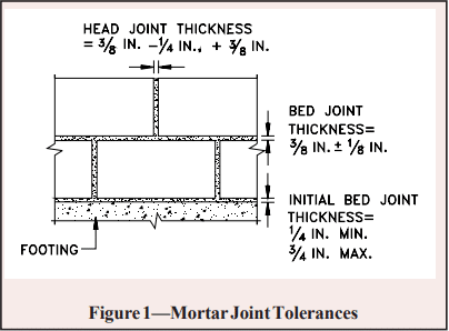
To make up for surface irregularities in the footing, the first course of masonry is set on a mortar bed joint which can range from 1/4 to 3/4 in. (6.4 to 19 mm) in thickness. This initial bed joint should fully bed the first course of masonry units, although mortar should not excessively protrude into cells that will be grouted.
All other mortar joints should be approximately 3/8 in. (9.5 mm) thick and, except for partially grouted masonry, need only provide face shell bedding for the masonry units. In partially grouted construction, webs adjacent to the grouted cells are mortared to restrict grout from flowing into ungrouted cores. Head joints must be filled solidly for a thickness equal to a face shell thickness of the units.
Tooled concave joints provide the greatest resistance to water penetration. On the exterior face of the wall, mortar joints may be cut flush if parging coats are to be applied.
When joint reinforcement is used, it should be placed directly on the block with mortar placed over the reinforcement in the usual method. A mortar cover of at least 5/8 in. (15.9 mm) should be provided between the exterior face of the wall and the joint reinforcement. A mortar cover of 1/2 in. (12.7 mm) is needed on the interior face of the wall. For added safety against corrosion, hot dipped galvanized joint reinforcement is recommended.
See Figures 1-4 for construction details.
Reinforced Masonry: For reinforced masonry construction, the reinforcing bars must be properly located to be fully functional. In most cases, vertical bars are positioned towards the interior face of basement walls to provide the greatest resistance to soil pressures. Bar positioners at the top and bottom of the wall prevent the bars from moving out of position during grouting. A space of at least 1/2 in. (12.7 mm) for coarse grout and 1/4 in. (6.4 mm) for fine grout should be maintained between the bar and the face shell of the block so that grout can flow completely around the reinforcing bars.
As mix water is absorbed by the units, voids can form in the grout. Accordingly, grout must be puddled or consolidated after placement to eliminate these voids and to increase the bond between the grout and the masonry units. Most codes permit puddling of grout when it is placed in lifts less than about 12 in. (305 mm). Lifts over 12 inches (305 mm) should be mechanically consolidated and then reconsolidated after about 3 to 10 minutes.
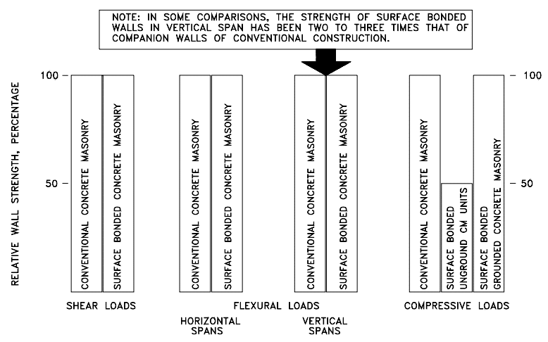
Surface Bonding: Another method of constructing concrete masonry walls is to dry stack units (without mortar) and then apply surface bonding mortar to both faces of the wall. The surface bonding mortar contains thousands of small glass fibers. When the mortar is applied properly to the required thickness, these fibers, along with the strength of the mortar itself, help produce walls of comparable strength to conventionally laid plain masonry walls. Surface bonded walls offer the benefits of excellent dampproof coatings on each face of the wall and ease of construction.
Dry-stacked walls should be laid in an initial full mortar bed to level the first course. Level coursing is maintained by using a rubbing stone to smooth small protrusions on the block surfaces and by inserting shims every two to four courses.
Water Penetration Resistance: Protecting below grade walls from water entry involves installation of a barrier to water and water vapor. An impervious barrier on the exterior wall surface can prevent moisture entry.
The barrier is part of a comprehensive system to prevent water penetration, which includes proper wall construction and the installation of drains, gutters, and proper grading.
Building codes (refs. 2, 4 , 5, 9, 13) typically require that basement walls be dampproofed for conditions where hydrostatic pressure will not occur, and waterproofed where hydrostatic pressures may exist. Dampproofing is appropriate where groundwater drainage is good, for example where granular backfill and a subsoil drainage system are present. Hydrostatic pressure may exist due to a high water table, or due to poorly draining backfill, such as heavy clay soils. Materials used for waterproofing are generally elastic, allowing them to span small cracks and accommodate minor movements.
When choosing a waterproof or dampproof system, consideration should be given to the degree of resistance to hydrostatic head of water, absorption characteristics, elasticity, stability in moist soil, resistance to mildew and algae, impact or puncture resistance, and abrasion resistance. A complete discussion of waterproofing, dampproofing, and drainage systems is included in TEK 19-03A (ref. 6).
All dampproofing and waterproofing systems should be applied to walls that are clean and free from dirt, mud and other materials which may reduce bond between the coating and the concrete masonry wall.
Draining water away from basement walls significantly reduces the pressure the walls must resist and reduces the possibility of water infiltration into the basement if the waterproofing (or dampproofing) system fails. Perforated pipe has historically proven satisfactory when properly installed. When placed on the exterior side of basement walls, perforated pipes are usually laid in crushed stone to facilitate drainage. To prevent migration of fine soil into the drains, filter fabrics are often placed over the gravel.
Drainage pipes can also be placed beneath the slab and connected into a sump. Pipes through the footing or the wall drain water from the exterior side of the basement wall.
The drainage and waterproofing systems should always be inspected prior to backfilling to ensure they are adequately placed. Any questionable workmanship or materials should be repaired at this stage since repairs are difficult and expensive after backfilling.
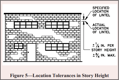
Backfilling: One of the most crucial aspects of basement construction is how and when to properly backfill. Walls should be properly braced or have the first floor in place prior to backfilling. Otherwise, a wall which is designed to be supported at the top may crack or even fail from the large soil pressures. Figure 5 shows one bracing scheme which has been widely used for residential basement walls. More substantial bracing may be required for high walls or large backfill pressures.
The backfill material should be free-draining soil without large stones, construction debris, organic materials, and frozen earth. Saturated soils, especially saturated clays, should generally not be used as backfill materials since wet materials significantly increase the hydrostatic pressure on the walls.
Backfill materials should be placed in several lifts and each layer should be compacted with small mechanical tampers. Care should be taken when placing the backfill materials to avoid damaging the drainage, waterproofing or exterior insulation systems. Sliding boulders and soil down steep slopes should thus be avoided since the high impact loads generated can damage not only the drainage and waterproofing systems but the wall as well. Likewise, heavy equipment should not be operated within about 3 feet (0.9 m) of any basement wall system.
The top 4 to 8 in. (102 to 203 mm) of backfill materials should be low permeability soil so rain water is absorbed into the backfill slowly. Grade should be sloped away from the basement at least 6 in. (152 mm) within 10 feet (3.1 m) of the building. If the ground naturally slopes toward the building, a shallow swale can be installed to redirect runoff.
Construction Tolerances
Specifications for Masonry Structures (ref. 8) specifies tolerances for concrete masonry construction. These tolerances were developed to avoid structurally impairing a wall because of improper placement.
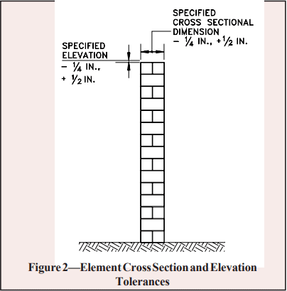
Dimension of elements in cross section or elevation …………………………………….¼ in. (6.4 mm), +½ in. (12.7 mm)
Mortar joint thickness: bed………………………..+⅛ in. (3.2 mm) head………………………………..-¼ in (6.4 mm), +⅜ in. (9.5 mm)
Elements
Variation from level: bed joints………………………………………. ±¼ in. (6.4 mm) in 10 ft (3.1 m), ±½ in. (12.7 mm) max top surface of bearing walls…………………………………………….. ±¼ in.(6.4 mm), +⅜ in.(9.5 mm), ±½ in.(12.7mm) max
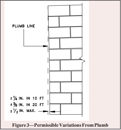
Variation from plumb………….±¼ in. (6.4 mm) 10 ft (3.1 m) ………………………………………±⅜ in. (9.5 mm) in 20 ft (6.1 m) ……………………………………………±½ in. (12.7 mm) maximum
True to a line…………………..±¼ in. (6.4 mm) in 10 ft (3.1 m) ………………………………………±⅜ in. (9.5 mm) in 20 ft (6.1 m) ……………………………………………±½ in. (12.7 mm) maximum
Alignment of columns and bearing walls (bottom versus top) ……………………………………………………………..±½ in (12.7 mm)
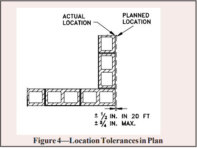
Location of elements
Indicated in plan……………..±½ in (12.7 mm) in 20 ft (6.1 m) …………………………………………….±¾ in. (19.1 mm) maximum
Indicated in elevation ……………………………………….±¼ in. (6.4 mm) in story height …………………………………………….±¾ in. (19.1 mm) maximum
Insulation: The thermal performance of a masonry wall depends on its R-value as well as the thermal mass of the wall. Rvalue describes the ability to resist heat flow; higher R-values give better insulating performance. The R-value is determined by the size and type of masonry unit, type and amount of insulation, and finish materials. Depending on the particular site conditions and owner’s preference, insulation may be placed on the outside of block walls, in the cores of hollow units, or on the interior of the walls.
Thermal mass describes the ability of materials like concrete masonry to store heat. Masonry walls remain warm or cool long after the heat or air-conditioning has shut off, keeping the interior comfortable. Thermal mass is most effective when insulation is placed on the exterior or in the cores of the block, where the masonry is in direct contact with the interior conditioned air.
Exterior insulated masonry walls typically use rigid board insulation adhered to the soil side of the wall. The insulation requires a protective finish where it is exposed above grade to maintain durability, integrity, and effectiveness.
Concrete masonry cores may be insulated with molded polystyrene inserts, expanded perlite or vermiculite granular fills, or foamed-in-place insulation. Inserts may be placed in the cores of conventional masonry units, or they may be used in block specifically designed to provide higher R-values.
Interior insulation typically consists of insulation installed between furring strips, finished with gypsum wall board or panelling. The insulation may be fibrous batt, rigid board, or fibrous blown-in insulation.
Design Features
Interior Finishes: Split faced, scored, burnished, and fluted block give owners and designers added options to standard block surfaces. Colored units can be used in the entire wall or in sections to achieve specific patterns.
Although construction with staggered vertical mortar joints (running bond) is standard for basement construction, the appearance of continuous vertical mortar joints (stacked bond pattern) can be achieved by using of scored units or reinforced masonry construction.
Natural Lighting: Because of the modular nature of concrete masonry, windows and window wells of a variety of shapes and sizes can be easily accommodated, giving basements warm, natural lighting. For additional protection and privacy, glass blocks can be incorporated in lieu of traditional glass windows.
References
Basement Manual-Design and Construction Using Concrete Masonry, CMU-MAN-002-01, Concrete Masonry & Hardscapes Association, 2001.
BOCA National Building Code. Country Club Hills, IL: Building Officials and Code Administrators International, Inc. (BOCA), 1999.
Building Code Requirements for Masonry Structures, ACI 530-02/ASCE 5-02/TMS 402-02. Reported by the Masonry Standards Joint Committee, 2002.
International Residential Code. Falls Church, VA: International Code Council, 2000.
International Building Code. Falls Church, VA: International Code Council, 2000.
Preventing Water Penetration in Below-Grade Concrete Masonry Walls, TEK 19-03A. Concrete Masonry & Hardscapes Association, 2001.
Seismic Design Provisions for Masonry Structures, TEK 14-18B, Concrete Masonry & Hardscapes Association, 2009.
Specifications for Masonry Structures, ACI 530.1-02/ASCE 6-99/TMS 602-02. Reported by the Masonry Standards Joint Committee, 2002.
Standard Building Code. Birmingham, AL: Southern Building Code Congress International, Inc. (SBCCI), 1999.
Standard Specification for Grout for Masonry, ASTM C 476-01. American Society for Testing and Materials, 2001.
Standard Specification for Load-Bearing Concrete Masonry Units, ASTM C 90-01. American Society for Testing and Materials, 2001.
Standard Specification for Mortar for Unit Masonry, ASTM C 270-00. American Society for Testing and Materials, 2000.
Uniform Building Code. Whittier, CA: International Conference of Building Officials (ICBO), 1997.
Construction of masonry wall systems is possible without the use of mortar. The use of standard CMU units laid dry and subsequently surface bonded with fiber reinforced surfaced bonding cement has been well documented in the past. (ref. 16) With the use of specially fabricated concrete masonry units known as “dry-stack units,” construction of these mortarless systems is simple, easy and cost effective. This TEK describes the construction and engineering design of such mortarless wall systems.
The provisions of this TEK apply to both specialty units manufactured specifically for dry-stack construction and conventional concrete masonry units with the following system types:
Grouted, partially grouted or surface bonded
Unreinforced, reinforced, or prestressed
Note that dry-stacked prestressed systems are available that do not contain grout or surface bonding. The provisions of this TEK do not apply to such systems due to a difference in design section properties (ref 8).
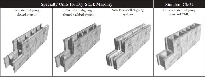
Specially designed units for dry-stack construction are available in many different configurations as shown in Figure 1. The latest and most sophisticated designs incorporate face shell alignment features that make units easier and faster to stack plumb and level. Other units are fabricated with a combination of keys, tabs or slots along both horizontal and vertical faces as shown in Figure 1 so that they may interlock easily when placed. Physical tolerances of dry-stack concrete units are limited to ±1/16 in. (1.58 mm.) which precludes the need for mortaring, grinding of face shell surfaces or shimming to even out courses during construction. Interlocking units placed in running bond resist flexural and shear stresses resulting from out-of-plane loads as a result of the keying action: (a) at the top of a web with the recess in the web of the unit above, (b) at two levels of bearing surface along each face shell at the bed joint, and (c) between adjacent blocks along the head joint. The first of these two interlocking mechanisms also ensures vertical alignment of blocks.
The interlocking features of dry-stack units improve alignment and leveling, reduce the need for skilled labor and reduce construction time. Floor and roof systems can be supported by mortarless walls with a bond beam at the top of the wall which expedites the construction process.
Wall strength and stability are greatly enhanced with grouting which provides the necessary integrity to resist forces applied parallel, and transverse to, the wall plane. Vertical alignment of webs ensures a continuous grout column even when the adjacent cell is left ungrouted. Grouting is necessary to develop flexural tensile stress normal to the bed joints, which is resisted through unit-mortar bond for traditional masonry construction. Strength of grouted dry-stack walls may also be enhanced by traditional reinforcement, prestressing, post-tensioning or with external fiber-reinforced surface coatings (surface bonding) as described in the next section.
Typical applications for mortarless concrete masonry include basement walls, foundation walls, retaining walls, exterior above-grade walls, internal bearing walls and partitions. Dry-stack masonry construction can prove to be a cost-effective solution for residential and low-rise commercial applications because of it’s speed and ease of construction, strength and stability even in zones of moderate and high seismicity. More information on design and construction of dry-stack masonry can be found in Reference 5.
Figure 1–– Dry-Stack Masonry Units
CONSTRUCTION
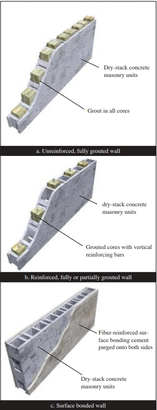
Dry-stack concrete masonry units can be used to construct walls that are grouted or partially grouted; unreinforced, reinforced or prestressed; or surface bonded. With each construction type, walls are built by first stacking concrete masonry units.
For unreinforced construction as shown in Figure 2a, grouting provides flexural and shear strength to a wall system. Flexural tensile stresses due to out-of-plane bending are resisted by the grout cores. Grout cores also interlace units placed in running bond and thus provide resistance to in-plane shear forces beyond that provided by friction developed along horizontal joints. Grout cores can also be reinforced to increase flexural strength.
Reinforcement can be placed vertically, in which case only those cells containing reinforcement may be grouted as shown in Figure 2b, as well as horizontally, in which case the masonry must be fully grouted. Another version is to place vertical prestressing tendons in place of reinforcement. Vertical axial compressive stress, applied via the tendons, increases flexural and shear capacity. Tendons may be bonded to grout, or unbonded, based upon the design. Placement of grout may be optional. Horizontally reinforced bond beam lintels can be created using a grout stop beneath the unit to contain grout.
As an alternative to reinforcing or prestressing, wall surfaces may be parged (coated) with a fiber-reinforced surface bonding cement/stucco per ASTM C887(ref. 14) as illustrated in Figure 2c. This surface treatment, applied to both faces of a wall, bonds concrete units together without the need for grout or internal reinforcement. The parging material bridges the units and fills the joints between units to provide additional bonding of the coating to the units through keying action. The compressive strength of the parging material should be equal to or greater than that of the masonry units.
Figure 2–– Basic Dry-Stack Masonry Wall Types
Laying of Units
The first course of dry-stack block should be placed on a smooth, level bearing surface of proper size and strength to ensure a plumb and stable wall. Minor roughness and variations in level can be corrected by setting the first course in mortar. Blocks should be laid in running bond such that cells will be aligned vertically.
Grout and Reinforcement
Grout and grouting procedures should be the same as used in conventional masonry construction (ref. 1, 10) except that the grout must have a compressive strength of at least 2600 psi (190 MPa) at 28 days when tested in accordance with ASTM C 1019 (ref.12). Placement of grout can be accomplished in one lift for single-story height walls less than 8 ft (2.43 m). Grout lifts must be consolidated with an internal vibrator with a head size less than 1 in. (25 mm).
Vertical Reinforcing
As for conventional reinforced masonry construction, good construction practice should include placement of reinforcing bars around door and window openings, at the ends, top and bottom of a wall, and between intersecting walls. Well detailed reinforcement such as this can help enhance nonlinear deformation capacity, or ductility, of masonry walls in building systems subjected to earthquake loadings – even for walls designed as unreinforced elements. Additional information on conventional grouting and reinforced masonry wall can be found in TEK 09-04A and TEK 03-03B (refs. 9 & 6).
Pre-stressed Walls
Mortarless walls can also be prestressed by placing vertical tendons through the cores. Tendons can be anchored within the concrete foundation at the base of a wall or in a bottom bond beam and are tensioned from the top of a wall.
Surface Bonded Walls
For walls strengthened with a surface bonding, a thin layer of portland cement surface bonding material should be troweled or sprayed on to a wall surface. The thickness of the surface coating should be at least ⅛ in. (3.2 mm.) or as required by the material supplier.
ENGINEERING PROPERTIES
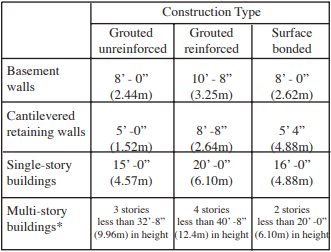
Walls constructed with mortarless masonry can be engineered using conventional engineering principles. Existing building code recommendations such as that produced by the building code (ref. 1) can serve as reference documents, but at the time of this printing it does not address mortarless masonry directly. It is thus considered an alternate engineered construction type. The International Building Code (ref. 7) does list allowable stresses based on gross-cross-sectional area for dry-stacked, surface-bonded concrete masonry walls. These values are the same as presented in TEK 03-05A (ref. 16). Suggested limits on wall or building height are given in Table 1.
Test data (refs. 2, 3 and 4) have shown that the strength of drystack walls exceeds the strength requirements of conventional masonry, and thus the recommended allowable stress design practices of the code can be used in most cases. When designing unreinforced, grouted masonry wall sections, it is important to deduct the thickness of the tension side face shell when determining the section properties for flexural resistance.
Table 1 –– Summary of Wall Heights for 8” (203 mm) Dry-stacked Units (ref. 5)
* Laterally supported at each floor
Unit and Masonry Compressive Strength
Units used for mortarless masonry construction are made of the same concrete mixes as used for conventional masonry units. Thus, compressive strength of typical units could vary between 2000 psi (13.79MPa) and 4000 psi. (27.58 MPa) Standard Methods of Sampling and Testing Concrete Masonry Units (ref. 11) can be referred to for determining strength of dry-stack units.
Masonry compressive strength f’m can conservatively be based on the unit-strength method of the building code (ref . 15), or be determined by testing prisms in accordance with ASTM C1314 (ref. 4). Test prisms can be either grouted or ungrouted depending on the type of wall construction specified.
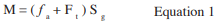
Because no mortar is used to resist flexural tension as for conventional masonry construction, flexural strength of mortarless masonry is developed through the grout, reinforcement or surface coating. For out-of-plane bending of solid grouted walls allowable flexural strength can be estimated based on flexural tensile strength of the grout per Equation 1.
Consideration should be given to the reduction in wall thickness at the bed joints when estimating geometrical properties of the net effective section.
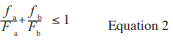
Correspondingly, flexural strength based on masonry compressive stress should be checked, particularly for walls resisting significant gravity loads, using the unity equation as given below.
Buckling should also be checked. (Ref. 8)
In-Plane Shear Strength
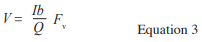
Shear strength for out-of-plane bending is usually not a concern since flexural strength governs design for this case. For resistance to horizontal forces applied parallel to the plane of a wall, Equation 3 may be used to estimate allowable shear strength.
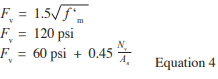
Fv is the allowable shear strength by the lesser of the three values given in Equation 4.
Grouted, Reinforced Construction
Mortarless masonry that is grouted and reinforced behaves much the same as for conventional reinforced and mortared construction. Because masonry tensile strength is neglected for mortared, reinforced construction, flexural mechanisms are essentially the same with or without the bed joints being mortared provided that the units subjected to compressive stress are in good contact. Thus, allowable stress design values can be determined using the same assumptions and requirements of the MSJC code. (ref.1)
Axial and flexural tensile stresses are assumed to be resisted entirely by the reinforcement. Strains in reinforcement and masonry compressive strains are assumed to vary linearly with their distance from the neutral axis. Stresses in reinforcement and masonry compressive stresses are assumed to vary linearly with strains. For purposes of estimating allowable flexural strengths, full bonding of reinforcement to grout are assumed such that strains in reinforcement are identical to those in the adjacent grout.
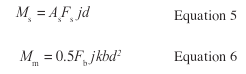
For out-of-plane loading where a single layer of vertical reinforcement is placed, allowable flexural strength can be estimated using the equations for conventional reinforcement with the lower value given by Equations 5 or 6.
In-Plane Shear Strength
Though the MSJC code recognizes reinforced masonry shear walls with no shear, or horizontal reinforcement, it is recommended that mortarless walls be rein- forced with both vertical and horizontal bars. In such case, allowable shear strength can be determined based on shear reinforcement provisions (ref. 1) with Equations 7, 8 and 9.
Where Fv is the masonry allowable shear stress per Equations 8 or 9.
Solid Grouted, Prestressed Construction
Mortarless masonry walls that are grouted and pre- stressed can be designed as unreinforced walls with the prestressing force acting to increase the vertical compres- sive stress. Grout can be used to increase the effective area of the wall. Flexural strength will be increased because of the increase in the fa term in Equation 1. Shear strength will be increased by the Nv term in Equation 4.
Because the prestressing force is a sustained force, creep effects must be considered in the masonry. Research on the long-term behavior of dry-stacked masonry by Marzahn and Konig (ref. 8) has shown that creep effects may be accentuated for mortarless masonry as a result of stress concentrations at the contact points of adjacent courses. Due to the roughness of the unit surfaces, high stress concentrations can result which can lead to higher non-proportional creep deformations. Thus, the creep coefficient was found to be dependent on the degree of roughness along bed-joint surfaces and the level of applied stress. As a result, larger losses in prestressing force is probable for dry-stack masonry.
Surface-Bonded Construction
Dry-stack walls with surface bonding develop their strength through the tensile strength of small fiberglass fibers in the 1/8” (3.8mm) thick troweled or surface bonded cement-plaster coating ASTM C-887(Ref. 14). Because no grouting is necessary, flexural tension and shear strength are developed through tensile resistance of fiberglass fibers applied to both surfaces of a wall. Test data has shown that surface bonding can result in a net flexural tension strength on the order of 300 psi.(2.07 MPa) Flexural capacity, based on this value, exceeds that for conventional, unreinforced mortared masonry construction, therefore it is considered conservative to apply the desired values of the code (ref. 1) for allowable flexural capacity for portland cement / lime type M for the full thickness of the face shell.
Out-of-Plane and In-Plane Flexural Strength
Surface-bonded walls can be considered as unreinforced and ungrouted walls with a net allowable flexural tensile strength based on the strength of the fiber-reinforcement. Flexural strength is developed by the face shells bonded by the mesh. Allowable flexural strength can be determined using Equation 1 with an Ft value determined on the basis of tests provided by the surface bonding cement supplier. Axial and flexural compressive stresses must also be checked per Equation 2 considering again only the face shells to resist stress.
Surface Bonded In-Plane Shear Strength
In-plane shear strength of surface-bonded walls is attributable to friction developed along the bed joints resulting from vertical compressive stress in addition to the diagonal tension strength of the fiber coating. If the enhancement in shear strength given by the fiber reinforced surface parging is equal to or greater than that provided by the mortar-unit bond in conventional masonry construction, then allowable shear strength values per the MSJC code (ref. 1) may be used. In such case, section properties used in Equation 3 should be based on the cross-section of the face shells.
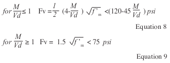
Figure 3 – A Mortarless Garden Wall Application
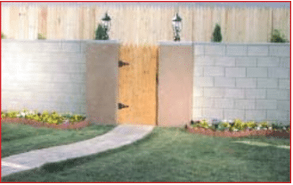
Figure 4 – A Residential, Mortarless, Single-Family Basement – Part of a 520 Home Development
REFERENCES
Building Code Requirements for Masonry Structures), ACI 530-02/ ASCE 5-02/TMS 402-02. Reported by the Masonry Standards Joint Committee (MSJC), 2002.
Drysdale, R.G., Properties of Dry-Stack Block, Windsor, Ontario, July 1999.
Drysdale, R.G., Properties of Surface-Bonded Dry-Stack Block Construction, Windsor, Ontario, January 2000.
Drysdale, R.G., Racking Tests of Dry-Stack Block, Windsor, Ontario, October 2000.
Drysdale, R.G., Design and Construction Guide for Azar Dry-Stack Block Construction, JNE Consulting, Ltd., February 2001.
Grout for Concrete Masonry, TEK 09-04A, Concrete Masonry & Hardscapes Association, 2002.
2000 International Building Code, Falls Church, VA. International Code Council, 2000.
Marzahn, G. and G. Konig, Experimental Investigation of Long-Term Behavior of Dry-Stacked Masonry, Journal of The Masonry Society, December 2002, pp. 9-21.
Hybrid Concrete Masonry Construction Details, TEK 0303B. Concrete Masonry & Hardscapes Association, 2009.
Specification for Masonry Structures, ACI 530.1-02/ASCE 6-02/ TMS 602-02. Reported by the Masonry Standards Joint Committee (MSJC), 2002.
Standard Methods of Sampling and Testing Concrete Masonry Units, ASTM C140-02a, ASTM International, Inc. , Philadelphia, 2002.
Standard Method of Sampling and Testing Grout, ASTM C1019-02, ASTM International, Inc., Philadelphia, 2002.
Standard Specification for Grout for Masonry, ASTM C 476-02. ASTM International, Inc., 2002
Standard Specification for Packaged, Dry, Combined Materials for Surface Bonding Mortar, ASTM C 887-79a (2001). ASTM International, Inc., 2001.
Standard Test Method for Compressive Strength of Masonry Assem blages, ASTM C1314-02a, ASTM International, Inc., Philadelphia, 2002.
An net cross-sectional area of masonry, in² (mm²) As effective cross-sectional area of reinforcement, in2 (mm2) b width of section, in. (mm) d distance from extreme compression fiber centroid of tension reinforcement, in. (mm) Fa allowable compressive stress due to axial load only, psi (MPa) Fb allowable compressive stress due to ß exure only, psi (MPa) Fs allowable tensile or compressive stress in reinforcement, psi (MPa) Ft flexural tensile strength of the grout, psi(MPa) Fv allowable shear stress in masonry psi (MPa) fa calculated vertical compressive stress due to axial load, psi (MPa) fb calculated compressive stress in masonry due to ß exure only, psi (MPa) f’ specified compressive strength of masonry, psi (MPa) I moment of inertia in.4 (mm4) j ratio of distance between centroid of flexural compressive forces and centroid of tensile forces to depth, d k ratio of the distance between compression face of the wall and neu tral axis to the effective depth d M maximum moment at the section under consideration, in.-lb (N-mm) Nv compressive force acting normal to the shear surface, lb (N) Q first moment about the neutral axis of a section of that portion of the cross section lying between the neutral axis and extreme fiber in.³ (mm³) Sg section modulus of uncracked net section in.³ (mm³) V shear force, lb (N)
The masonry arch, one of mans’ oldest architectural forms, is defined as a rigid span curving upward between two points of support. The arch appears in a wide variety of structures ranging from the purely decorative triumphal arch to the masonry arch bridge where it sustains great loads.
The round arch, Figure 1, was used by the early Chinese in all types of buildings. In ancient Egypt, this arch and others were used in nonceremonial structures such as engineering works and private dwellings. The Babylonians, on the other hand, used their arches in temples, palaces, and tombs. The Romans used the arch freely in their secular structures, as in the Colosseum, and in their engineering works like the aqueduct, but in their temples they followed the Greek style with the horizontal entablature.
Many forms of the arch have been developed during the centuries of its use, ranging from the flat or jack arch through the segmental, circular, parabolic to the pointed Gothic. Used freely in the great cathedrals of Europe, the Gothic or pointed arch had a structural use more important than the ornamental effect, as it minimized the outward thrust, making possible the firmness and stability combined with the lofty and spacious interior characteristic of the Gothic cathedral.
Two distinct types of arches have been recognized based on span, rise, and loading. The more common concrete masonry arch is the minor arch where maximum span is limited to about 6 feet (1.8 m) with a rise-to-span ratio not exceeding 0.15, and carrying loads up to 1500 lb per foot of span (21,891 N/m). The second type of arch is the major arch where span, rise, and loading may exceed those of the minor. Illustrations of both types of arches are shown in Figure 1. However, the design section of this TEK discusses only minor arches.
Figure 1—Masonry Arch Forms
ANALYSIS
Fixed masonry arches are statically indeterminate to the third degree, that is, they have three reaction components or force paths that could be eliminated without adversely effecting their stability. This redundancy is a hidden asset of masonry; the tendency for “arching action” provides a masonry wall with resistance to progressive type failure. When a hole is caused suddenly in a masonry wall, an arch is created over the opening and the wall continues to carry load rather than fall down.
This redundancy of the masonry arch is, however, a nuisance when one considers design. Because the masonry arch is statically indeterminate, arches in building walls are generally designed or analyzed by approximate methods; the degree of exactness of the design procedure depends upon the size (span & rise) of the arch. Minor arches with spans of up to 6 feet (1.8 m) and rise-to-span ratios not exceeding 0.15 may be satisfactorily designed by the hypothesis of least crown thrust first proposed by Mosely in 1837. Major arches may be designed by considering them as essentially thick curved elastic beams. Many methods of elastic analysis have been developed; however, in most instances the application is complicated and time consuming. And, it is still an approximate analysis since the equations are developed assuming that deformations within the arch are small enough that the stresses are not affected if these deformations are ignored. This is not true of long span bridges where secondary stresses are significant and are taken into account. In masonry arches for building walls they can be ignored safely.
Figure 2 shows the forces and reactions within and upon a minor concrete masonry arch. The external load may consist of a uniform load, w, as shown, a concentrated load, or other. A horizontal thrust, H, is assumed to act at the crown, and its point of application is assumed to be at the upper middle-third limit (upper edge of kern) of the arch section. At the skewback (left-hand reaction), a reaction, F, is assumed to act at the lower middle-third limit (lower edge of kern) of the section. These assumptions for the design of minor arches, that the equilibrium polygon lies entirely within the middle third of the arch section, preclude the rotation of one section of the arch about the edge of a joint or the development of tensile stresses in either the intrados or extrados. The assumptions appear reasonable for symmetrical arches loaded equally and symmetrically, but may not be tenable for unsymmetrical arches or nonuniform loading. A vertical shear, VO, is shown also at the crown of the arch. This shear will equal zero when both halves of the arch are loaded equally, i.e., the general case.
There are four items to consider regarding structural failure of minor unreinforced concrete masonry arches:
failure due to tensile stresses (already eliminated by the assumption that the force polygon remains within the section kern)
crushing of the masonry due to compression by the horizontal thrust, H
shear sliding failure of one section of the arch along another, or along the skewback
the ability of supporting adjacent masonry wall or abutment to safely resist the horizontal thrust, H, of the arch.
Consider first the crushing of the masonry due to horizontal thrust. For minor arches (segmental or jack arches) the relationship between vertical loading or vertical reaction, V1 or W, and horizontal thrust, H, depends on the rise-to-span ratio, r/S, of the arch, and on the span/depth ratio, S/d. This relationship is shown in Figure 3. Knowing r/S and S/d of an arch, read the value W/2 H at the left-hand side of the graph. (Note: flat or jack arches are represented as r/S = 0).
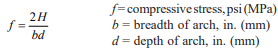
Once the horizontal thrust has been determined, the maximum compressive stress in the masonry is determined by the following formula:
This value is twice an axial compressive stress on the arch due to a load H because the horizontal thrust is located at the edge of the kern.
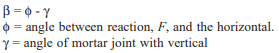
Shear stress, or sliding of one section of the arch on another or on the skewback, requires consideration of the angular relationship of the reaction and the mortar joint, Figure 4. Stresses acting on the joint will depend on the angle formed between the reaction, F, and the inclined joint. This angle is:
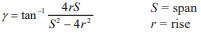
For segmental arches with radial joints, the angle between the skewback and the vertical is:
or in terms of radius of curvature, R:
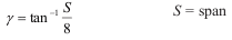
For jack or flat arches in which the skewback equals ½ inch per foot of span (83 mm/m) for each 4 inches (102 mm) of arch depth, the angle that the skewback makes with the vertical is:
In these ratios all terms of length must be expressed in the same units; for example, in computing S/r, S/d, and S/R, if S is in feet (m), r, d, and R must be in feet (m) also.
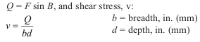
Shear force, Q, along the mortar joint is then equal to:
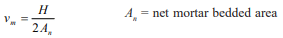
Finally, a check should be made to make certain the supporting adjacent masonry wall has sufficient shear strength and resistance to overturning against the horizontal thrust, H, of the concrete masonry arch. Figure 5 illustrates how shear resistance may be calculated. It is assumed that the horizontal thrust of the arch attempts to move a volume of masonry enclosed by the boundary lines ABCD and CDEF. The thrust, H, is acting against two shear planes of resistance, CF and DE. Shear stress along either plane can then be calculated as:
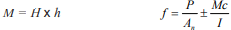
The tendency for the arch thrust, H, to overturn the supporting masonry wall must be checked, especially when the arch is near the wall top. No tension due to overturning moment should be permitted in the supporting wall section. Applicable equations are:
M = overturning moment due to thrust H h = wall height f = stress at bottom of wall P = vertical load on wall An = net area of wall I = moment of inertia of wall based on length and equivalent solid thickness c = distance from neutral axis, 1/2 wall length
Figure 2—Assumed Conditions for Static Analysis of Small Concrete Masonry Arch
Figure 3—Relationship of Vertical Load, W, and Horizontal Thrust, H, in Small Concrete Masonry Arches
Figure 4—Angular Relationship Between Forces and Stresses in Radial Joint of Segmental and/or Jack Arches
Figure 5—Supporting Adjacent Masonry Must Resist the Horizontal Thrust of the Arch
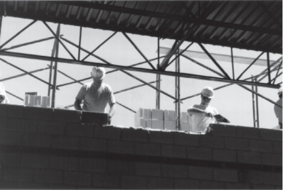
CONSTRUCTION
Since any section of an arch may be subjected to shear, moment, and thrust, it is important that arches be constructed with high quality concrete masonry units, mortar, and good workmanship. For this reason, the use of mortar conforming to ASTM C 270 (ref. 5), Type M, S, or N is recommended. Bond is an important factor in building arches with sufficient shear resistance to withstand the imposed loads. To obtain good bond, all mortar joints in the arch need to be completely filled. This is sometimes very difficult to do, especially where the concrete masonry units are laid in soldier bond or rowlock header bond. It is also hard to do where the curvature of the arch is of short radius, and mortar joints of varying thickness are used. But completely filled joints are paramount to a strong arch, and can be achieved with quality workmanship.
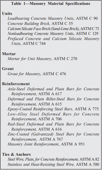
Concrete masonry units for arch construction should be either 100 percent solid units, or filled units, or filled cell construction. Applicable ASTM Specifications are: Concrete Building Brick, ASTM C 55 (ref. 3); Calcium Silicate Face Brick, ASTM C 73 (Sand-Lime Brick) (ref. 2); Load-Bearing Concrete Masonry Units, ASTM C 90 (ref. 4).
Concrete masonry arches are constructed with the aid of a form or temporary support. After construction, the form is kept in place until the arch is strong enough to carry the loads to which it will be subjected. For unreinforced concrete masonry arches, the form should remain in place about one week after construction.
Finally, the wall supporting the concrete masonry arch must be considered. With a masonry arch, three conditions relating to the supporting wall must be maintained in order to ensure arch action: the length of the span must remain constant; the elevation of the arch ends must remain unchanged; and the inclination of the skewback must remain fixed. If any of these conditions are violated by sliding, settlement, or rotation of the supporting abutments, critical stresses for which the arch was not designed may result.
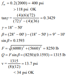
DESIGN EXAMPLE—SEGMENTAL ARCH
A segmental arch is to be supported on an unreinforced 8-inch (203 mm) hollow loadbearing wall. One end of the arch will be 24 inches (610 mm) from the end of the wall. Other given data are:
Span, S = 72 in. (1829 mm) Depth, d = 12 in. (305 mm) Breadth, b = 8 in. (203 mm) Rise, r = 6 in. (152 mm) Uniform load = 1000 lb/ft (14.6 kN/m) f’m = 2000 psi (13.8 MPa) vm = 34 psi (0.23 MPa), Type S mortar
ANALYSIS:
r/S = 6/72 = 0.083 S/d = 72/12 = 6 W = 6 x 1000 lb/ft = 6000 lb
From Figure 3, W/2H = 0.53
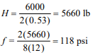
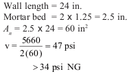
Check thrust against wall:
SUMMARY: The arch is sufficient to carry the loads, but the supporting wall will require reinforcement to increase its shear capacity.
REFERENCES
Leontorich, V. Frames and Arches. McGraw-Hill, 1959.
Standard Specification for Calcium Silicate Face Brick (Sand-Lime Brick), ASTM C 73-94. American Society for Testing and Materials, 1994.
Standard Specification for Concrete Building Brick, ASTM C 55-94. American Society for Testing and Materials, 1994.
Standard Specification for Load-Bearing Concrete Masonry Units, ASTM C 90-94. American Society for Testing and Materials, 1994.
Standard Specification for Mortar for Unit Masonry, ASTM C 270-92a. American Society for Testing and Materials, 1992.
Portland cement-based plaster has many useful applications: as a moisture resistant coating for concrete masonry walls; as an interior wall finish in residential and commercial structures; and as an exterior architectural treatment for buildings of all types.
The terms cement plaster and cement stucco are used interchangeably. They both describe a combination of cement and aggregate mixed with a suitable amount of water to form a plastic mixture that will adhere to a surface and preserve the texture imposed on it.
When freshly mixed, plaster is a pliable, easily workable material. It can be applied either by hand or machine in two or three coats, although two-coat applications are more typical when plaster is applied to newly constructed concrete masonry.
While plaster may be used as an interior or exterior finish for most building materials, some type of metal reinforcement or mechanical keying system is usually required to effectively attach the plaster to the substrate. Concrete masonry, however, provides an excellent base for plaster without the need for reinforcement. Since block is manufactured of the same cementitious material as that in the plaster, the two have a natural affinity.
MATERIALS
Of primary importance to the performance of the finished surface is the selection and use of proper materials. Each must be evaluated on its ability to provide serviceability, durability, and satisfactory appearance. Standard Specification for Application of Portland Cement-Based Plaster, ASTM C 926 (ref. 3) includes specifications for materials for use in plaster
Cement
Cement should comply to one of the following product specifications:
Blended hydraulic cement —ASTM C 595 (ref. 4) Types IP, IP(M), IS, IS(M), and their air-entrained counterparts IP-A, IP(M)-A, IS-A, IS(M)-A
Masonry cement—ASTM C 91 (ref. 5) Types M, S, N
Portland cement—ASTM C 150 (ref. 6) Types I, II, III, and their air-entrained counterparts IA, IIA, IIIA
Plastic cement—UBC 25-1 (ref. 1)
White portland cement—ASTM C 150 (ref. 6) Types I, IA, III, IIIA
Aggregates
Aggregates used in plaster should conform to the chemical and physical requirements of ASTM C 897, Standard Specification for Aggregate For Job-Mixed Portland Cement Plasters (ref. 2), except as noted below. Recommendations for gradation of the sand to be used in the base coat are listed in Table 1.
Aggregates used for finish coats need not comply with the gradation requirements of ASTM C 897. Various sizes and shapes can be evaluated with test panels to obtain special textures or finishes. As a starting point, all aggregates for finish-coat plaster should be below a No. 16 sieve and uniformly graded. Uniform gradation produces plaster that is easier to apply. If necessary, larger aggregate may be added to obtain the desired appearance.
MIXTURES
Properly proportioned mixtures can be recognized by their workability, ease of application, adhesiveness to the base, and resistance to sagging.
The combinations of cementitious materials and aggregates shown in Table 2 have proven to provide satisfactory performance. These proportions are recommended for first and second coat applications.
Considerations in selecting the plaster mix include suction of the masonry, its surface irregularities, climate extremes, extent of surface exposure, and method of application. For economy and simplicity, it is better to select the same plaster type for both scratch (first) and brown coat (second coat in a three coat application) applications, adjusting the proportions for the brown coat to allow for a larger aggregate to cement ratio.
The finish coat can be varied in appearance by changing the size and shape of the aggregate, by adding color, by changing the consistency of the finish mix, and by the application method. For the finish coat, a factory prepared mixture may be used or the finish coat may be proportioned and mixed at the jobsite. Job-mixed finish coat plaster will provide a truer color and more pleasing appearance if white portland cement is used in conjunction with a fine-graded, light colored sand. Recommendations for job mixed finish coat proportions are listed in Table 3.
The success of plastering depends on proper batching and mixing of the individual and combined materials. Water is placed in the mixer first, after which half of the sand is added. Next the cement and any admixtures are added. Finally, the balance of the sand is added and mixing is continued until the batch is uniform and of the proper consistency, which usually takes 3 or 4 minutes.
Although batching by shovelfuls remains the most commonly used method in the field, shovelful batching should be checked daily by volume measures to establish both the required number of shovelfuls of each ingredient and the volume of mortar in the mixer when a batch is properly proportioned. Water additions should also be batched using containers of known volume. Proper mixing should result in a uniform blend of all materials.
PLASTER APPLICATION
Open textured concrete masonry units, laid with flush (nontooled) joints, should be specified on walls intended to be plastered. The open texture promotes a good mechanical bond between the plaster and the masonry. New concrete masonry walls should be properly aligned and free from any surface contamination, such as mortar droppings or sand. It is important that the wall be properly cured and carrying almost all of its design dead load before the plaster is applied. Existing masonry walls should be inspected for alignment, and any coatings or surface treatments other than portland cement paint be should removed by sandblasting prior to plastering.
Plaster may be applied by hand or machine in two or three coats in accordance with the thicknesses given in Table 4. Two-coat application is most often used when plaster is applied directly to concrete masonry, and for horizontal (overhead) plaster application.
The scratch coat can be applied either from the bottom to the top of the work area, or from top to bottom. The plaster must be applied with sufficient force to fully adhere it to the masonry. Excessive troweling or movement of the scratch coat must be avoided, because too much action will break the bond between the plaster and masonry. The applied plaster must be brought to the required thickness and the surface made plumb. The thickness is established by the use of screeds and grounds. A rod or straightedge is used to even the surface when the area between the screeds and grounds is filled with plaster. The rod can bear on the screeds or contact the grounds and be moved over the surface, cutting off high spots and showing up the hollow spaces, which must be filled and rodded again.
Scratch-coat plasters are scored or scratched to promote mechanical bond when the brown coat is applied. The scratch coat should be scored in a horizontal direction; shallow scratching is adequate.
Brown-coat plasters are applied, rodded, and floated to even the surface, provide a uniform suction throughout the basecoat plaster, and provide a desirable surface for the finish coat.
The brown coat is applied in sufficient thickness to bring the surface to the proper plane. A few minutes after the plaster has been applied, the surface is rodded to the desired plane. The plaster thickness is properly gaged with plaster screeds or wood slats of proper thickness as the guides. After rodding, the surface is floated to give it the correct surface texture.
Floating of the brown coat is the most important part of plastering. Floating must be done only after the plaster has lost sufficient moisture so that the surface sheen has disappeared but before the plaster has become so rigid that it cannot be moved under the float. This interval is critical, since the degree of consolidation that occurs during floating influences the shrinkage-cracking characteristics of the plaster.
The full thickness of the base coats should be applied as rapidly as the two coats can be put in place. The second coat should be applied as soon as the first coat is sufficiently rigid to resist the pressures of second-coat application without cracking. Under certain conditions this may mean applying both first and second coats in a single day. The short delay, or even no delay, between the first and second coats promotes more intimate contact between them and more complete curing of the base coat. No stoppage of plaster should occur within a panel. The finish coat is applied to a predamped, but still absorptive, base coat to a thickness of about 1/8 in. (3.2 mm). The finish coat is applied from the top down and the whole wall surface must be covered without joinings (laps or interruptions). Table 4 summarizes the recommended nominal plaster coat thicknesses for both two and three coat work.
Differential suction between the masonry units and mortar joints may cause joint patterns to be visible in two coat applications if the first coat is too thin. This may also occur if the walls are plastered while the units contain excessive moisture.
CONTROL JOINTS
Cracks can develop in plaster from a number of causes: drying shrinkage stresses; building movement; foundation settlement; intersecting walls, ceilings, and pilasters; weakened sections in a wall from a reduction in service area or cross section because of fenestration; severe thermal changes; and construction joints.
To prevent such cracking, install control joints in the plaster coat directly over and aligned with any control joints in the base. Normally, cracking will not occur in plaster applied to uncracked masonry bases if the plaster bonds tightly to the base structure. If excessive cracking does occur, the application (particularly floating) procedure may not have provided adequate bond of plaster to concrete masonry. Altering application procedures or mechanically anchoring the plaster to the concrete masonry surface with mesh may be required.
CURING
To obtain the best results from the cementitious materials in cement plaster, moisture must be kept in the plaster for the first few days after application. The base coat should be moist cured until the finish coat is applied. Generally, fogging the surface with water at the start and again at the end of the work day will suffice. If it is hot, dry, and windy, the plaster surface should be moistened and covered with a single sheet of polyethylene plastic, weighted or taped down to prevent water loss through evaporation.
Immediately before finish-coat application, the base coat should be moistened. This moisture absorbed by the base coat and the ambient relative humidity provides total curing of the finish coat plaster (particularly colored finish coats) so that it is not necessary to further moist-cure the finish coat.
MAINTENANCE OF PLASTER
Minimal care will keep plaster attractive for many years. Washing will keep the surface clean and the color bright. Washing plaster wall surfaces consists of three steps:
Prewet the wall, saturating it. Start at the bottom and work to the top.
Use a garden hose to direct a high-pressure stream of water against the wall to loosen the dirt. Start at the top and wash the dirt down the wall to the bottom.
Flush remaining dirt off the wall with a follow-up stream.
Prewetting overcomes absorption and prevents dirty wash water from being absorbed and dulling the finish. A jet nozzle on a garden hose will usually clean effectively. Do not hold the nozzle too close to the surface because the high pressure stream of water may erode the surface.
Chipped corners and small spalls can be patched with premixed mortar. The patch area should be wetted before applying plaster. Prepare premixed mortar by adding water and mixing to a doughy consistency, then trowel into the patch area, and finish to match the texture of the surrounding surface.
A fresh, new look can be given to any exterior plaster wall by applying a surface treatment of paint, portland cement paint, or other coating. Portland cement paints are mixed with clean water to a brushable consistency and laid on heavily enough to fill and seal small cracks and holes. The surface should be dampened immediately before application.
REFERENCES
Plastic Cement, Uniform Building Code Standard 25-1, International Conference of Building Officials (ICBO), 1994.
Standard Specification for Aggregate for Job-Mixed Portland Cement-Based Plasters, ASTM C 897-00. American Society for Testing and Materials, 2000.
Standard Specification for Application of Portland Cement Based Plaster, ASTM C 926-98a. American Society for Testing and Materials, 1998.
Standard Specification for Blended Hydraulic Cements, ASTM C 595-02. American Society for Testing and Materials, 2002.
Standard Specification for Masonry Cement, ASTM C 91-
American Society for Testing and Materials, 2001.
Standard Specification for Portland Cement, ASTM C 150-
For masonry construction, productivity is typically thought of as the number of concrete masonry units placed per unit of time. This production rate is influenced by many factors, some of which can be controlled by the mason and others which are beyond the mason’s control.
PRODUCTIVITY RATES
Ideally, concrete masonry productivity rates should be compiled by masonry estimators, based on records of completed jobs. Published productivity rates, such as those shown in Figure 1 and Table 1, should be used as guidelines only.
The following sections discuss some of the various factors that can impact masonry productivity. In addition to these, productivity rates can vary with unit size and concrete density, mortar workability, masonry bond pattern, number and type of wall openings, amount of reinforcement and wall size.
As illustrated in Figure 1, concrete ma-primarily in running bond, other bond patterns often require more time to lay. For example, stack bond has been estimated to decrease productivity by about 8% over comparable running bond productivity rates (ref. 4).
Bond pattern can also affect productivity. Because masonry crews are accustomed to laying concrete masonry primarily in running bond, other bond patterns often require more time to lay. For example, stack bond has been estimated to decrease productivity by about 8% over comparable running bond productivity rates (ref. 4).
IMPACT OF QUALITY ON PRODUCTIVITY
The overall quality of the project can influence the masonry productivity. Quality construction includes:
pre-bid and pre-construction conferences,
proper design,
attention to planning and layout,
quality materials,
adequate jobsite and
proper installation.
A project with these ingredients will also be conducive to a very productive jobsite.
Pre-Bid and Pre-Construction Conferences
Pre-bid and pre-construction conferences should be held and attended by all parties involved in the masonry work including the owner’s representative, the architect/engineer, the contractor, the construction manager, the masonry material suppliers and the mason contractor. This facilitates good communication prior to the commencement of work and prior to the development of any misunderstandings. Clear communication minimizes delays due to factors such as lastminute changes and errors.
Proper Design
Quality design means that the designer has:
designed and detailed a project that is constructible,
developed plans and specifications that are sufficient for construction and are complete with the proper code and standards referenced,
reviewed the plans, specifications and structural drawings to eliminate conflicting words and conflicting details,
included the input of a quality mason contractor, and
incorporated all masonry materials into CSI Division 4. (Often, some mason materials are found in division 7. If all of the mason’s work is placed into Division 4, it enhances communication with the masonry team and has a better chance of being properly incorporated into the job.) Similar to the pre-bid and pre construction conferences, a comprehensive set of plans and specifications will help enhance productivity because it will reduce or eliminate time spent correcting misunderstandings and errors.
A complete set of plans and specifications will include a copy of Building Code Requirements for Masonry Structures and Specification for Masonry Structures (refs. 1, 2), the national consensus standards for masonry design and construction. In addition, applicable ASTM standards should be included for specifying masonry materials.
Planning and Layout
Attention to planning of the building itself and of construction sequencing and scheduling can impact masonry productivity.
Concrete masonry structures can be constructed using virtually any layout dimension. However, for maximum construction efficiency and economy, concrete masonry elements should be designed and constructed with modular coordination in mind. Modular coordination is the practice of laying out and dimensioning structures to standard lengths and heights to accommodate modular sized building materials. Standard concrete masonry modules are typically 8 in. (203 mm) vertically and horizontally, but may also include 4in. (102 mm) modules for some applications. These modules provide the best overall design flexibility and coordination with other building products such as windows and doors. Typically, masonry opening widths for doors and windows should be 4 in. (102 mm) larger than the door or window width. This allows for 2 in. (51 mm) on each side of the opening for framing. Masonry opening heights for windows typically are 8 in. (203 mm) greater than the window height. This opening size allows for 2 in. (51 mm) above and below for framing and 4 in. (102 mm) for installing a sill at the bottom of the window. Masonry opening door heights are 2 in. (51 mm) greater than the door height, which leaves 2 in. (51 mm) for the door framing. Figure 2 illustrates these opening sizes.
Thus, door and window widths of 28 in., 36 in., 44 in., and 52 in. (711, 914, 1118 and 1,321 mm), and so on in 8 in. (203 mm) increments, are modular and would not require cutting of the masonry. Modular window heights are any multiple of 8 in. (203 mm), with a masonry window opening 8 in. (203 mm) greater than the height of the window if a 4 in. (102 mm) sill will be used. Similarly, a modular door height is 2 in. (51 mm) less than any multiple of eight. Thus, an 86 in. (2,184 mm) high door, which fits into an 88-in. (2,235 mm) high masonry opening, has a modular height.
Note that products are available in some locations to accommodate 6’ 8” (2,032 mm) doors in masonry walls without the need for cutting the masonry units. These include precast lintels with a 2 in. (51 mm) notch which provides the necessary 6’ 10” (2,083 mm) masonry opening to accommodate the door and frame. In other areas, door frames are available with a 4 in. (101.6 mm) header which would allow a 6’ 8” (2,032 mm) door to fit into 7’ 4” or 88 in. (2,235 mm) high masonry opening.
Nonmodular layouts may require additional considerations for items such as using nonstandard units or saw cutting masonry units and maintaining bond patterns. Additionally, other construction issues may arise, such as placement of jamb reinforcement and adequate grout consolidation within small core spaces. The end product typically is more difficult to construct, produces more waste and is more costly.
Similarly, coordinating the placement of pipes, ducts, chases and conduits to align them with hollow masonry cores can reduce the need to saw-cut masonry units.
Steel congestion in reinforced masonry can slow productivity. Placing too many reinforcing bars in too small a space makes it difficult to place the steel and to provide adequate grout coverage. Specification for Masonry Structures (ref. 3) requires 1/4 in. (6.4 mm) clear space between the reinforcing bar and the masonry for fine grout and 1/2 in. (13 mm) clear space for coarse grout.
Sample panels reduce misunderstandings and provide an objective indicator of the intended construction practices. They help ensure all parties understand the range of materials, methods and workmanship acceptable on the job. Sample panels are typically at least 4 ft by 4 ft (1.22 x 1.22 m) and should contain the full range of unit and mortar colors. Selecting units of all one shade for the sample panel will not accurately reflect the completed work. Instead, units should be randomly selected as they would in the project construction. Cleaning procedures, sealant application and all other procedures should be performed on the sample panel so that their acceptability can be judged as well. The sample panel should remain in place throughout construction as a point of reference.
For maximum productivity, timely delivery of the units, mortar, grout and other masonry materials will help expedite the job. In addition, schedule masonry work to avoid times of the year particularly subject to freezing temperatures or prolonged rains whenever possible. Although masonry construction can take place during hot, cold and wet weather conditions, special construction procedures may be warranted in some cases to ensure the masonry quality is not impacted by the weather. More detailed information on these construction procedures can be found in All-Weather Concrete Masonry Construction (ref. 4).
Quality Materials
Masonry materials have a successful history of meeting applicable specifications and project requirements. Ensuring that the materials used are as specified helps keep the masonry construction on track. ASTM standards for masonry units, for example, specify dimensional tolerances for the units. Units meeting the ASTM tolerances will be easier to place, and allow the mason to more easily maintain level and alignment. Similarly, units without excessive chippage (a characteristic also governed by ASTM standards) allow placement without the need for sorting the product for quality—an activity that reduces overall productivity.
Jobsite
A quality jobsite helps productivity by including ample space for the mason subcontractor to work and having easy access to the masonry supplies. This includes having:
undisturbed space for building the sample panel(s),
a defined and ample-sized area for materials and supplies, and
a defined and ample-sized area for sampling and testing procedures as required for the project.
Proper Installation
In addition to the factors cited above, quality installation requires:
an ample number of qualified craftsmen,
qualified and sufficient supervision, and
the right equipment for the job.
There have been some marvelous developments in products and equipment to assist masons and hence increase masonry productivity. For example, newer fork lifts often have increased capacity, a single boom which increases visibility, are more maneuverable, have higher load ratings and higher extensions. Other equipment advances that can enhance productivity include portable hand-held lasers that work in numerous directions simultaneously, electric portable winches and power (crank-up or hydraulic) scaffolding. Products that are easier for the mason to install, such as self-adhesive flashings and pre-formed flashing end dams, can also impact masonry productivity.
Choice of mortar can also impact productivity. Masonry and mortar cements provide more consistency because all of the cementitious ingredients are premixed. Premixed mortars, which include the sand mixed with the appropriate cement, are also available in silos or in mixers or blenders. Premixed mortars can improve mortar quality control and uniformity and can also increase productivity by eliminating the need for job site mixing.
In some cases, work by other trades can also impact masonry productivity. For example, poured concrete foundations or footings which do not meet their tolerances may require the mason to saw-cut the first course of block, or take some other measure, to compensate.
REFERENCES
Building Code Requirements for Masonry Structures, ACI 530-02/ASCE 5-02/TMS 402-02. Reported by the Masonry Standards Joint Committee, 2002.
Specification for Masonry Structures, ACI 530.1-02/ ASCE 6-02/TMS 602-02. Reported by the Masonry Standards Joint Committee, 2002.
Prestressing is the general term used when a structural element is compressed prior to being subjected to building loads. This initial state of compression offsets tensile stresses from applied loads. Post-tensioning is a specific method of prestressing where tendons are stressed after the wall has been placed. The other type of prestressing, called pretensioning, involves tensioning the tendon prior to construction of the masonry. Because virtually all prestressed masonry built to date has been post-tensioned, the two terms are often used interchangeably as they apply to this form of masonry design and construction.
Post-tensioned concrete masonry walls have been built for schools, retail, manufacturing, highway sound barriers, warehouses and other types of structures. In addition, posttensioning has been used to strengthen and repair existing masonry walls. This TEK addresses new concrete masonry walls laid in running bond and built with unbonded vertical posttensioning tendons. Post-Tensioned Concrete Masonry Wall Design, TEK 14-20A (ref. 1) addresses the structural design of vertically post-tensioned walls.
POST-TENSIONING
In post-tensioned construction, hollow concrete masonry units are laid conventionally and prestressing tendons are either placed in the concrete masonry cells or in the cavity between multiple wythes. Current design codes (ref. 3) typically address post-tensioning of masonry walls laid in running bond. The cells or cavity containing the tendons may or may not be grouted. Grouting helps increase cross-sectional area for shear and compressive resistance, but increases construction cost and time.
Prestressing tendons are either installed during wall construction, or access ports are left in the walls so the tendons can be slipped in after the walls are completed. In either case, the tendons are tensioned only after the walls have cured for approximately three to seven days.
MATERIALS
Construction of a post-tensioned wall proceeds similarly to that of conventional masonry. The materials are the same, with the addition of hardware to develop the posttensioning forces, steel prestressing tendons which can be wires, bars or strands, and sometimes prestressing grout.
Concrete Masonry Units
Open-ended (Aand H-shaped) concrete masonry units (Figure 1) are particularly suited to post-tensioned masonry, as these units can be placed around the tendons without having to lift the units over the tendons. While these two-core units are commonly used, proprietary units are also being developed that are specifically intended for use with tendons.
The net area strength of concrete masonry units must be at least 1,900 psi (13.1 MPa) per Standard Specification for Loadbearing Concrete Masonry Units (ref. 2). However, stronger units are often specified for post-tensioned walls to utilize the higher compressive strength.
Mortar and Grout
Type S mortar is commonly used for conventional loadbearing masonry, and Type S is a good choice for posttensioned masonry as well. Higher early strength mortars can accommodate earlier stressing.
Because mortar must be placed on concrete masonry webs adjacent to grouted cores to contain the fluid grout, full mortar bedding is sometimes specified when grout is used. Mortar bedding is a design issue as well, as the section properties of a wall with face shell mortar bedding are different from those of a fully bedded wall.
Because this TEK addresses unbonded tendons only, the grout discussed here is conventional grout (ASTM C 476, ref. 6), not prestressing grout. Prestressing grout is only used with bonded tendons. Encasing tendons in conventional grout restrains the tendons, but they are still considered unbonded.
Tendons
In the United States, tendons are usually high-strength bars joined by couplers, although Building Code Requirements for Masonry Structures (ref. 3) also allows steel strands or wires to be used. Couplers allow the use of shorter bars which minimizes the height of lifting. To date, there are no code provisions for tendons which are not steel.
Important features of the tendons are their size, strength, and relaxation characteristics. Most tendons currently available in the United States are bars between 7/16 and 1 in. (11 and 25 mm) in diameter, with strengths between 60,000 and 100,000 psi (413 and 690 MPa), depending on the supplier. Steel strand tendons are generally 270,000 psi (1,860 MPa). Tendons are usually placed in hollow cells of masonry units with little or no grouting, except for certain shear walls (these must be identified on the design drawings). In addition, the open-ended units shown in Figure 1 must be grouted to meet minimum web requirements in ASTM C 90 (ref. 2).
Tendon Corrosion Protection
Tendons must be protected from moisture deterioration, and the design documents should indicate the type of protection required. Tendons in walls with a likelihood of high moisture levels (single wythe exterior walls in areas of high humidity and interior walls around swimming pools, locker rooms, etc.) must have corrosion protection in addition to that provided by the masonry cover, such as hot-dipped galvanizing (ref. 3). In practice, most prestressing tendons are supplied with a hotdipped galvanized coating. It is considered good practice to use additional corrosion protection, such as flexible epoxy-type coatings, for tendons in moist environments.
Grouting
While the need for grouting is minimized compared to conventionally reinforced walls, grout is still needed for mild reinforcement, anchorages for the tendons, such as in bond beams, and tendon restraints.
Anchorages
Each tendon is anchored at the foundation and extends to the top of the wall. Building Code Requirements for Masonry Structures (ref. 3) requires that tendons be anchored by mechanical embedments or bearing devices or by bond development in concrete. Tendons can not be anchored by bond development into the masonry. The foundation anchorage is embedded in the wall or footing while the top anchorage utilizes a special block, a precast concrete spreader beam or a grouted bond beam.
Unless the design documents call out specific bottom anchors, the contractor must select the anchor appropriate to the conditions. The cast-in-place bottom anchor (Figure 2a) is preferred for shear walls and for fire walls. While they are the best anchors for capacity, cast-in-place anchors are the most difficult to align. Cast-in-place anchors are often set by the foundation contractor, not the mason. Thus, quality control is a concern with these anchors.
The mason controls bottom anchor placement when either adhesive anchors are installed in the foundation (Figure 2c), or when an anchor is used which does not rely on the foundation for support (Figure 2b). If the anchor in Figure 2b is used, foundation dowels are grouted into the wall to lock it in place. In some instances, tendons can also begin at an upper floor and not at the foundation. In this case, the foundationless anchor is used with a bond beam, similar to Figure 2b.
The mechanical post-installed anchors can be used for nearly all applications, while the adhesive type should not be used for fire walls.
CONSTRUCTION
Key steps of post-tensioning concrete masonry walls include: selecting and setting the bottom anchorages; installing the tendons; selecting and setting the top anchorages; and a tensioning the tendons.
Bottom Anchors
Bottom anchors are most critical to the proper construction of post-tensioned walls. Alignment is essential to ensure that the tendons are placed exactly as intended.
Tendons
Tendons are usually placed concentric with the wall. However, they may be placed off-center to counteract bending moments due to eccentric vertical forces or lateral forces from a single direction. However, tendons should not be placed such that tensile stresses develop in the wall due to the combination of prestressing force and dead load.
Laterally-unrestrained tendons are free to move within the cell or cavity and are the simplest to construct. Laterally restrained tendons are not free to move within a cell or cavity. Restraint is accomplished by grouting the full height of the tendon or by providing intermittent restraints—either grout plugs or mechanical restraints—at the quarter points of the wall height.
Placing tendons is much like that of mild reinforcement. They may be installed after the masonry is constructed provided the design allows laterally-unrestrained tendons. If laterally restrained tendons are required, the tendon placement should proceed simultaneously with the masonry to allow the restraints to be installed unless the cells will be grouted.
Tendon positioners (see Figure 3) are useful to maintain the tendon location within the wall during construction of the masonry. Positioners may also function as restraints if their capacity is determined by testing.
In all details, the tendons must be able to slip freely. If grout encases the tendon either totally or at restraints or bond beams, a bond breaker such as poly tape should be used to allow the tendon to slip.
Tendons can also be either bonded or unbonded. Bonded tendons are encapsulated by prestressing grout in a corrugated duct which is bonded to the surrounding masonry by grout. Both the prestressing grout inside the duct and the grout around the duct must be cured before the tendons are stressed. Thus, bonded tendons are also laterally-restrained. All other tendons are unbonded. However, unbonded tendons may be either laterally-restrained or unrestrained. Walls with laterally unrestrained and unbonded tendons do not require grouting and are generally the most economical to construct. However, the wall performance will not be as good as with laterally restrained tendons. The designer must specify which system will be used.
For some conditions, primarily seismic, grouted conventional reinforcement is used in addition to post-tensioning tendons to provide minimum requirements of bonded reinforcement. However, post-tensioned walls are most economical when the grouting is minimized or eliminated totally in comparison to a conventionally reinforced wall. The higher cost of the post-tensioning materials is more than offset by the savings of placing fewer tendons compared to reinforcing bars and eliminating most of the grouting.
Top Anchors
The top anchor must be placed on solid masonry, a grouted bond beam or a precast concrete unit. The anchor should not be supported by mortar.
Figure 4 shows a means for supporting the top of a wall when the top anchor is placed on a bond beam in a lower course. This detail can also be used for interior partitions.
Tensioning
At the time the tendons are stressed, the masonry is considered to have its initial strength (f ‘mi). The project specification should include either the minimum f ‘mi and minimum specified compressive strength of masonry ( f ‘m), or the amount of curing required before stressing can occur.
The sequence of tensioning, whether it is accomplished by fully stressing each tendon sequentially or by stressing the tendons in stages, is a function of the design specifications. Prestressed masonry design, and therefore the structural integrity of these walls, relies on an accurate measure of the prestress in the tendons. To ensure the required level of accuracy, Specification for Masonry Structures (ref. 4) requires that the following two methods be used to evaluate the tendon prestressing force:
1. measure the tendon elongation and compare it with required elongation based on average load-elongation curves for the prestressing tendons, and either:
2a. use a calibrated dynamometer to measure the jacking force on a calibrated gage, or
2b. for prestressing tendons using bars of less than 150 ksi (1,034 MPa) tensile strength, use load-indicating washers complying with Standard Specification for Compressible-Washer-Type Direct Tension Indicators for Use with Structural Fasteners, ASTM F 959 (ref. 5). If the two values determined by methods 1 and 2 are not within 7 percent of each other, the cause of the difference must be corrected.
QUALITY ASSURANCE
Post-tensioned walls must be constructed in conformance with masonry standards applicable to conventionally reinforced masonry. In addition to these, Specification for Masonry Structures (ref. 4) requires the following for posttensioned masonry:
In the out-of-plane direction, the tolerance for the tendon placement shall be + 1/4 in. (6 mm) for masonry beams, columns, walls, and pilasters with cross-sectional dimensions less than 8 in. (203 mm). For cross-sectional dimensions greater than 8 in. (203 mm), the tolerance increases to + 3/8 in. (10 mm).
In the in-plane direction, the tolerance for tendon placement is +1in. (25 mm).
If tolerances exceed these amounts, the Architect/Engineer should evaluate the effect on the structure.
Standard Specification for Loadbearing Concrete Masonry Units, ASTM C 90-01a. ASTM International, 2001.
Building Code Requirements for Masonry Structures, ACI 530-02/ASCE 5-02/TMS 402-02. Reported by the Masonry Standards Joint Committee, 2002.
Specification for Masonry Structures, ACI 530.1-02/ASCE 6-02/TMS 602-02. Reported by the Masonry Standards Joint Committee, 2002.
Standard Specification for Compressible-Washer- Type Direct Tension Indicators for Use with Structural Fasteners, ASTM F 959-01a. ASTM International, 2001.
Standard Specification for Grout for Masonry, ASTM C 476-01. ASTM International, 2001.
Concrete masonry is a popular building material because of its strength, durability, economy, and its resistance to fire, noise, and insects. To function as designed however, concrete masonry buildings must be constructed properly.
This TEK provides a brief overview of the variety of materials and construction methods currently applicable to concrete masonry. In addition, a typical construction sequence is described in detail.
MATERIALS
The constituent masonry materials: concrete block, mortar, grout, and steel, each contribute to the performance of a masonry structure. Concrete masonry units provide strength, durability, fire resistance, energy efficiency, and sound attenuation to a wall system. In addition, concrete masonry units are manufactured in a wide variety of sizes, shapes, colors, and architectural finishes achieve any number of appearances and functions. The Concrete Masonry Shapes and Sizes Manual (ref. 4) illustrates a broad sampling of available units.
While mortar constitutes approximately 7% of a typical masonry wall area, its influence on the performance of a wall is significant. Mortar bonds the individual masonry units together, allowing them to act as a composite structural assembly. In addition, mortar seals joints against moisture and air leakage and bonds to joint reinforcement, anchors, and ties to help ensure all elements perform as a unit.
Grout is used to fill masonry cores or wall cavities to improve the structural performance and/or fire resistance of masonry. Grout is most commonly used in reinforced construction, to structurally bond the steel reinforcing bars to the masonry, allowing the two elements to act as one unit in resisting loads.
Reinforcement incorporated into concrete masonry structures increases strength and ductility, providing increased resistance to applied loads and, in the case of horizontal reinforcement, to shrinkage cracking.
Specifications governing material requirements are listed in Table 1.
Table 1—Masonry Material Specifications
CONSTRUCTION METHODS
Mortared Construction
Most concrete masonry construction is mortared construction, i.e., units are bonded together with mortar. Varying the bond or joint pattern of a concrete masonry wall can create a wide variety of interesting and attractive appearances. In addition, the strength of the masonry can be influenced by the bond pattern. The most traditional bond pattern for concrete masonry is running bond, where vertical head joints are offset by half the unit length.
Excluding running bond construction, the most popular bond pattern with concrete masonry units is stack bond. Although stack bond typically refers to masonry constructed so that the head joints are vertically aligned, it is defined as masonry laid such that the head joints in successive courses are horizontally offset less than one quarter the unit length (ref. 2). Concrete Masonry Bond Patterns (ref. 3), shows a variety of bond patterns and describes their characteristics.
Dry-Stacked Construction
The alternative to mortared construction is dry-stacked (also called surface bonded) construction, where units are placed without any mortar, then both surfaces of the wall are coated with surface bonding material. Shims or ground units are used to maintain elevations. This construction method results in faster construction, and is less dependent on the skill of the laborer than mortared construction. In addition, the surface bonding coating provides excellent rain penetration resistance. Surface Bonded Concrete Masonry Construction (ref. 9), contains further information on this method of construction.
CONSTRUCTION SEQUENCE
Mixing Mortar
To achieve consistent mortar from batch to batch, the same quantities of materials should be added to the mixer, and they should be added in the same order. Mortar mixing times, placement methods, and tooling must also be consistent to achieve uniform mortar for the entire job.
In concrete masonry construction, site-mixing of mortar should ideally be performed in a mechanical mixer to ensure proper uniformity throughout the batch. Mortar materials should be placed in the mixer in a similar manner from batch to batch to maintain consistent mortar properties. Typically, about half the mixing water is added first into a mixer. Approximately half the sand is then added, followed by any lime. The cement and the remainder of the sand are then added. As the mortar is mixed and begins to stiffen, the rest of the water is added. Specification for Masonry Structures (ref. 7) requires that these materials be mixed for 3 to 5 minutes. If the mortar is not mixed long enough, the mortar mixture may not attain the uniformity necessary for the desired performance. A longer mixing time can increase workability, water retention, and board life.
The mortar should stick to the trowel when it is picked up, and slide off the trowel easily as it is spread. Mortar should also hold enough water so that the mortar on the board will not lose workability too quickly, and to allow the mason to spread mortar bed joints ahead of the masonry construction. The mortar must also be stiff enough to initially support the weight of the concrete masonry units.
To help keep mortar moist, the mortarboard should be moistened when a fresh batch is loaded. When mortar on the board does start to dry out due to evaporation, it should be retempered. To retemper, the mortar is mixed with a small amount of additional water to improve the workability. After a significant amount of the cement has hydrated, retempering will no longer be effective. For this reason, mortar can be retempered for only 1 ½ to 2 ½ hours after initial mixing, depending on the site conditions. For example, dry, hot, and windy conditions will shorten the board life, and damp, cool, calm conditions will increase the board life of the mortar. Mortar should be discarded if it shows signs of hardening or if 2 ½ hours have passed since the original mixing.
Placing Mortar
Head and bed joints are typically ⅜ in. (10 mm) thick, except at foundations. Mortar should extend fully across bedding surfaces of hollow units for the thickness of the face shell, so that joints will be completely filled. Solid units are required to be fully bedded in mortar.
Although it is important to provide sufficient mortar to properly bed concrete masonry units, excessive mortar should not extend into drainage cavities or into cores to be grouted. For grouted masonry, mortar protrusions extending more than ½ in. (13 mm) into cells or cavities to be grouted should be removed (ref. 7).
The Importance of Laying to the Line
Experienced masons state that they can lay about five times as many masonry units when working to a mason line than when using just their straightedge. The mason line gives the mason a guide to lay the block straight, plumb, at the right height, and level. The line is attached so that it gives a guide in aligning the top of the course.
If a long course is to be laid, a trig may be placed at one or more points along the line to keep the line from sagging. Before work begins, the mason should check to see that the line is level, tight, and will not pull out.
Each mason working to the same line needs to be careful not to lay a unit so it touches the line. This will throw the line off slightly and cause the rest of the course to be laid out of alignment. The line should be checked from time to time to be certain it has remained in position.
Placement of Concrete Masonry Units
PLACING UNITS
The Foundation
Before building the block wall, the foundation must be level, and clean so that mortar will properly adhere. It must also be reasonably level. The foundation should be free of ice, dirt, oil, mud, and other substances that would reduce bond.
Laying Out the Wall
Taking measurements from the foundation or floor plan and transferring those measurements to the foundation, footing, or floor slab is the first step in laying out the wall.
Once two points of a measurement are established, corner to corner, a chalk line is marked on the surface of the foundation to establish the line to which the face of the block will be laid. Since a chalk line can be washed away by rain, a grease crayon, line paint, nail or screwdriver can mark the surface for key points along the chalk line, and a chalk line re-snapped along these key points. After the entire surface is marked for locations of walls, openings, and control joints, a final check of all measurements should be made.
The Dry Run—Stringing Out The First Course
Starting with the corners, the mason lays the first course without any mortar so a visual check can be made between the dimensions on the floor or foundation plan and how the first course actually fits the plan. During this dry layout, concrete blocks will be strung along the entire width and length of the foundation, floor slab, and even across openings. This will show the mason how bond will be maintained above the opening. It is helpful to have ⅜ in. (10 mm) wide pieces of wood to place between block as they are laid dry, to simulate the mortar joints.
At this dry run the mason can check how the block will space for openings which are above the first course—windows, etc., by taking away block from the first course and checking the spacing for the block at the higher level. These checks will show whether or not units will need to be cut. Window and door openings should be double checked with the window shop drawings prior to construction.
When this is done, the mason marks the exact location and angle of the corners. It is essential that the corner be built as shown on the foundation or floor plan, to maintain modular dimensions.
Laying the Corner Units
Building the corners is the most precise job facing the mason as corners will guide the construction of the rest of the wall. A corner pole can make this job easier. A corner pole is any type of post which can be braced into a true vertical position and which will hold a taut mason’s line without bending. Corner poles for concrete block walls should be marked every 4 or 8 in. (102 to 203 mm), depending on the course height, and the marks on both poles must be aligned such that the mason’s line is level between them.
Once the corner poles are properly aligned, the first course of masonry is laid in mortar. Typically, a mortar joint between ¼ and ¾ in. (6.4 to 19 mm) is needed to make up for irregularities of the footing surface. The initial bed joint should be a full bed joint on the foundation, footing, or slab. In some areas, it is common practice to wet set the initial course of masonry directly in the still damp concrete foundation.
Where reinforcing bars are projecting from the foundation footing or slab, the first course is not laid in a full mortar bed. In this case, the mason leaves a space around the reinforcing bars so that the block will be seated in mortar but the mortar will not cover the area adjacent to the dowels. This permits the grout to bond directly to the foundation in these locations.
After spreading the mortar on the marked foundation, the first block of the corner is carefully positioned. It is essential that this first course be plumb and level.
Once the corner block is in place, the lead blocks are set— three or four blocks leading out from each side of the corner. The head joints are buttered in advance and each block is lightly shoved against the block in place. This shove will help make a tighter fit of the head joint, but should not be so strong as to move the block already in place. Care should be taken to spread mortar for the full height of the head joint so voids and gaps do not occur.
If the mason is not working with a corner pole, the first course leads are checked for level, plumb, and alignment with a level.
Corners and leads are usually built to scaffold height, with each course being stepped back one half block from the course below. The second course will be laid in either a full mortar bed or with face shell bedding, as specified.
Laying the Wall
Each course between the corners can now be laid easily by stretching a line between. It should be noted that a block has thicker webs and face shells on top than it has on the bottom. The thicker part of the webs should be laid facing up. This provides a hand hold for the mason and more surface area for mortar to be spread. The first course of block is thereafter laid from corner to corner, allowing for openings, with a closure block to complete the course. It is important that the mortar for the closure block be spread so all edges of the opening between blocks and all edges of the closure block are buttered before the closure block is carefully set in place. Also, the location of the closure block should be varied from course to course so as not to build a weak spot into the wall.
The units are leveled and plumbed while the mortar is still soft and pliable, to prevent a loss of mortar bond if the units need to be adjusted.
As each block is put in place, the mortar which is squeezed out should be cut off with the edge of the trowel and care should be taken that the mortar doesn’t fall off the trowel onto the wall or smear the block as it is being taken off. Should some mortar get on the wall, it is best to let it dry before taking it off.
All squeezed out mortar which is cut from the mortar joints can either be thrown back onto the mortar board or used to butter the head joints of block in place. Mortar which has fallen onto the ground or scaffold should never be reused.
At this point, the mason should:
Use a straightedge to assure the wall is level, plumb and aligned.
Be sure all mortar joints are cut flush with the wall, awaiting tooling, if necessary.
Check the bond pattern to ensure it is correct and that the spacing of the head joints is right. For running bond, this is done by placing the straightedge diagonally across the wall. If the spacing of head joints is correct, all the edges of the block will be touched by the straightedge.
Check to see that there are no pinholes or gaps in the mortar joints. If there are, and if the mortar has not yet taken its first set, these mortar joint defects should be repaired with fresh mortar. If the mortar has set, the only way they can be repaired is to dig out the mortar joint where it needs repairing, and tuckpoint fresh mortar in its place.
Tooling Joints
When the mortar is thumbprint hard, the head joints are tooled, then the horizontal joints are finished with a sled runner and any burrs which develop are flicked off with the blade of the trowel. When finishing joints, it is important to press firmly, without digging into the joints. This compresses the surface of the joint, increasing water resistance, and also promotes bond between the mortar and the block. Unless otherwise required, joints should be tooled with a rounded jointer, producing a concave joint. Once the joints are tooled, the wall is ready for cleaning.
Cleanup
Masonry surfaces should be cleaned of imperfections that may detract from the final appearance of the masonry structure including stains, efflorescence, mortar droppings, grout droppings, and general debris.
Cleaning is most effective when performed during the wall construction. Procedures such as skillfully cutting off excess mortar and brushing the wall clean before scaffolding is raised, help reduce the amount of cleaning required.
When mortar does fall on the block surface, it can often be removed more effectively by letting it dry and then knocking it off the surface. If there is some staining on the face of the block, it can be rubbed off with a piece of broken block, or brushed off with a stiff brush.
Masons will sometimes purposefully not spend extra time to keep the surface of the masonry clean during construction because more aggressive cleaning methods may have been specified once the wall is completed. This is often the case for grouted masonry construction where grout smears can be common and overall cleaning may be necessary.
The method of cleaning should be chosen carefully as aggressive cleaning methods may alter the appearance of the masonry. The method of cleaning can be tested on the sample panel or in an inconspicuous location to verify that it is acceptable.
Specification for Masonry Structures (ref. 7) states that all uncompleted masonry work should be covered at the top for protection from the weather.
DIMENSIONAL TOLERANCES
While maintaining tight construction tolerances is desirable to the appearance, and potentially to the structural integrity of a building, it must be recognized that factors such as the condition of previous construction and nonmodularity of the project may require the mason to vary the masonry construction slightly from the intended plans or specifications. An example of this is when a mason must vary head or bed joint thicknesses to fit within a frame or other preexisting construction. The ease and flexibility with which masonry construction accommodates such change is one advantage to using masonry. However, masonry should still be constructed within certain tolerances to ensure the strength and appearance of the masonry is not compromised.
Specification for Masonry Structures (ref. 7) contains site tolerances for masonry construction which allow for deviations in the construction that do not significantly alter the structural integrity of the structure. Tighter tolerances may be required by the project documents to ensure the fi- nal overall appearance of the masonry is acceptable. If site tolerances are not being met or cannot be met due to previous construction, the Architect/Engineer should be notified.
Mortar Joint Tolerances
Mortar joint tolerances are illustrated in Figure 1. Al- though bed joints should be constructed level, they are permitted to vary by ± ½ in. (13 mm) maximum from level provided the joint does not slope more than ± ¼ in. (6.4 mm) in 10 ft (3.1 m).
Collar joints, grout spaces, and cavity widths are permitted to vary by –¼ in. to +⅜ in. (6.4 to 9.5 mm). Provisions for cavity width are for the space between wythes of non-composite masonry. The provisions do not apply to situations where the masonry extends past floor slabs or spandrel beams.
Figure 1—Mortar Joint Tolerances
Dimensions of Masonry Elements
Figure 2 shows tolerances that apply to walls, columns, and other masonry building elements. It is important to note that the specified dimensions of concrete masonry units are ⅜ in. (9.5 mm) less than the nominal dimensions. Thus a wall specified to be constructed of 8 in. (203 mm) concrete masonry units should not be rejected because it is 7 ⅝ in. (194 mm) thick, less than the apparent minimum of 7 ¾ in. (197 1 mm) (8 in. (203 mm) minus the ¼ in. (6.4 mm) tolerance). Instead the tolerance should be applied to the 7 ⅝ in. (194 mm) specified dimension.
Figure 2—Element Cross Section and Elevation Tolerances
Plumb, Alignment, and Levelness of Masonry Elements
Tolerances for plumbness of masonry walls, columns, and other building elements are shown in Figure 3. Masonry building elements should also maintain true to a line within the same tolerances as variations from plumb.
Columns and walls continuing from one story to another may vary in alignment by ± ¾ in. (19 mm) for nonloadbearing walls or columns and by ± ½ in. (13 mm) for bearing walls or columns.
The top surface of bearing walls should remain level within a slope of ± ¼ in. (6.4 mm) in 10 ft (3.1 m), but no more than ± ½ in. (13 mm).
Figure 3—Permissible Variations From Plumb
Location of Elements
Requirements for location of elements are shown in Figures 4 and 5.
Figure 4—Location Tolerances in Plan
Figure 5—Location Tolerances in Story Height
REFERENCES
Building Block Walls, VO 6. National Concrete Masonry Association, 1988.
Building Code Requirements for Masonry Structures, ACI 530-99/ASCE 5-99/TMS 402-99. Reported by the Masonry Standards Joint Committee, 1999.
Concrete Masonry Bond Patterns, TEK 14-06, Concrete Masonry & Hardscapes Association, 2004.
Nolan, K. J. Masonry & Concrete Construction. Craftsman Book Company, 1982.
Specification for Masonry Structures, ACI 530.1-99/ASCE 6-99/TMS 602-99. Reported by the Masonry Standards Joint Committee, 1999.
Standard Specification for Loadbearing Concrete Masonry Units, ASTM C 90-00. American Society for Testing and Materials, 2000.
Surface bonding is an economical construction technique which was first introduced in the late sixties by the U. S. Department of Agriculture for use in low cost housing. In surface bonded construction, concrete masonry units are laid dry and stacked, without mortar, to form walls. Walls are constructed with units that have been precision ground or honed to achieve a uniform bearing surface, or with shims placed periodically to maintain a level and plumb condition. Both sides of the wall are then coated with a thin layer of reinforced surface bonding mortar. The synthetic fibers which reinforce the surface bonding mortar impart a tensile strength of about 1500 psi (10.3 MPa), producing a strong wall despite the relatively thin thickness of material on each side. The surface coating on each side of the wall bonds the concrete masonry units together in a strong composite construction, and serves as a protective water resistant shield.
Surface bonded concrete masonry has a number of advantages:
Less time and skill are required for wall construction. In a 1972 study of mason productivity sponsored by the U. S. Department of Housing and Urban Development and other interested organizations, it was found that surface bonded concrete masonry construction resulted in 70 percent greater productivity than that achievable with conventional construction.
The surface bonding mortar provides excellent resistance to water penetration in addition to its function of holding the units together. Tests of surface bonded walls have repeatedly shown their resistance to wind driven rain to be “excellent” even with wind velocities as great as 100 mph (161 km/h), and over test periods of 8 hours.
Colored pigment can be incorporated into the surface bonding mortar to produce a finished surface without the need to paint.
Surface bonded concrete masonry construction offers all of the benefits and advantages of conventional concrete masonry construction, such as:
fire safety
acoustic insulation
energy efficiency
lasting durability and beauty
DESIGN STRENGTH
Many structural and nonstructural tests have been performed on surface bonded walls to establish design parameters for the system.
The nonstructural properties, such as sound transmission class, fire resistance period, and energy efficiency, of surface bonded concrete masonry can be considered equivalent to a conventional mortared concrete masonry wall.
There are a few differences between the structural properties of the two types of construction. These differences are discussed in the following paragraphs, and are illustrated in Figure 1 for ungrouted, unreinforced walls. Although national building codes, such as the BOCA National Building Code and the Standard Building Code (refs. 1, 3) do not specifically address reinforced or grouted surface bonded walls, manufacturers of surface bonding mortars may have code-approved criteria for their products.
Compressive Loads
Resistance to vertical compressive loads depends primarily on the compressive strength of the concrete block used in the wall construction. Stronger units make stronger walls. With mortared construction, a rule of thumb is that the wall strength will generally be about seventy percent of the unit strength. In comparison, surface bonded walls built with unground concrete masonry units develop approximately thirty percent of the strength of the individual block. This reduced wall strength is depicted in Figure 1 for walls constructed with unground concrete masonry units.
The lower value obtained with the unground units is due to a lack of solid bearing contact between units, due to the natural roughness of the concrete units. The mortar bed used in conventional construction compensates for this roughness and provides a uniform bearing between units. If the masonry unit bearing surfaces are ground flat and smooth before the wall is erected, results similar to those for a mortared wall can be expected. In Figure 1, note that surface bonded walls built with precision ground concrete masonry units are equally as strong in compression as the conventional construction.
Flexural Resistance
The flexural strength of a surface bonded wall is about the same as that of a conventional mortared wall, as shown in Figure 1. When walls are tested in the vertical span (i.e., a horizontal force, such as wind, is applied to a wall that is supported at the top and bottom) surfaced bonded walls and mortared walls have about the same average strength; failure occurs in the surface bonded coating due to tensile stress at or near one of the horizontal joints. With mortared construction, failure occurs at a horizontal joint with bond failure between the mortar and the masonry units. The data from numerous tests on surface bonded constructions led to an allowable stress of 18 psi (0.12 MPa) based on the gross area.
When walls are laid in a running bond pattern, either with mortar joints or with surface bonding, and tested in the horizontal span, (i.e., a wall supported at each end is subjected to a horizontal wind force) the strength in bending depends primarily on the strength of the units. This is due to the interlocking of the masonry units laid when in a running bond configuration. In such tests in the horizontal span, the wall strength of the surface bonded wall is exactly the same as the conventional construction. In Table 1, an allowable flexural stress of 30 psi (0.21 MPa) is recommended for horizontal span when the units have been laid in running bond.
Shear Strength
The shear resistance of surface bonded construction is the same as that of conventional walls. With face shell mortar bedding, conventional concrete masonry walls averaged 42 psi (0.29 MPa) shear resistance, based on gross area. Nine surface bonded walls, 8 in. (203 mm) in thickness, had an average shear resistance of 39 psi (0.27 MPa), and three 6 in. (152 mm) thick surface bonded walls averaged 40 psi (0.28 MPa). These data are compared in Figure 1, and led to a recommended allowable shear stress of 10 psi (0.07 MPa) on the gross area (see Table 1).
Figure 1—Surface Bonded and Mortared Concrete Masonry Wall Strengths
CONSTRUCTION
The construction procedure for surface bonded walls is similar to that of conventional, except that mortar is not placed between the masonry units. Standard Practice for Construction of Dry-Stacked, Surface-Bonded Walls, ASTM C946 (ref. 4), governs the construction methods. Care should be taken to ensure uncoated walls are adequately braced.
Because the walls are constructed without mortar joints, surface bonded wall dimensions do not conform to the standard 4 in. (102 mm) design module. Wall and opening dimensions should be based on actual unit dimensions, which are typically 7 ⅝ in. high by 15 ⅝ in. long (194 by 397 mm).
Materials
Surface bonding mortar should comply with Standard Specification for Packaged, Dry, Combined Materials for Surface Bonding Mortar, ASTM C887 (ref. 6), which governs flexural and compressive strength, sampling, and testing. ASTM C946 requires Type I, moisture-controlled, concrete masonry units be used for surface bonded construction. Type I units must be in a dry condition when delivered to the job site. Walls laid using dry units will undergo less drying shrinkage after construction, hence minimizing cracks. Standard Specification for Loadbearing Concrete Masonry Units, ASTM C90 (ref. 5) governs these requirements.
As for mortared masonry construction, materials should be properly stored on site to prevent contamination by rain, ground water, mud, and other materials likely to cause staining or to have other deleterious effects.
If the bearing surfaces of the concrete masonry units are unground, metal or plastic shims or mortar may occasionally be required between units to maintain the wall level and plumb. Shims must have a minimum compressive strength of 2,000 psi (13.8 MPa) to ensure their long term durability after the wall is loaded. Metal shims, if used, should be corrosion resistant to reduce the possibility that they will corrode and bleed through the finished masonry at a later time.
Leveling
Because the footing is not typically level enough to lay up the dry units without additional leveling, the first course of masonry units is laid in a mortar bed or set in the fresh footing concrete to obtain a level base for the remainder of the wall. Vertical head joints should not be mortared, even when the first course is mortar bedded, since mortar in the head joints will misalign the coursing along the wall length.
When required, additional leveling courses are constructed in the wall. Leveling courses should be placed when:
the wall is out of level by more than ½ in. (13 mm) in 10 ft,
at each floor level, and
at a horizontal change in wall thickness (see Figure 2).
After the first course of masonry units is laid level in a mortar bed, dry stacking proceeds with the remaining courses beginning with the corners, and followed by stacking, in running bond, between the corners. As they are dry stacked, the ends of the concrete masonry units should be butted together tightly. Small burrs should be removed prior to placement.
After every fourth course, the wall should be checked for plumb and level.
Figure 2—Change in Wall Thickness
Crack Control
Temperature and moisture movements have the potential to cause small vertical cracks in a masonry wall. These cracks are an aesthetic, rather than a structural, concern. In exposed concrete masonry, where shrinkage cracks may be objectionable, horizontal joint reinforcement, control joints, or bond beams are used to control cracking. The absence of a mortar bed joint in surface bonded walls means that there is no space in the wall for joint reinforcement, so control joints or bond beams are used for crack control.
Control joints should be placed:
at wall openings and at changes in wall height and thickness
at wall intersections, at pilasters, chases, and recesses
in walls without openings, at intervals of 20 ft (6.1 m) when there are no bond beams in the construction, and at intervals of 60 ft (18.3 m) when bond beams are incorporated every 4 ft (1.2 m) vertically.
Control joints for surface bonded walls are similar to those for mortared concrete masonry. At the control joint location, the surface bonding mortar should be raked out and the joint caulked.
Placing Accessories & Utilities
The absence of a mortar bed joint in the construction also requires that the face shell and/or the cross web of the concrete masonry units be notched or depressed whenever wall ties or anchors must be embedded in the wall. A coarse rasp is typically used to make small notches, while deeper notches are cut with a masonry saw. Cores containing anchors or wall ties should be grouted, or other adequate anchorage should be provided.
Electrical lines and plumbing are often located in the cores of concrete masonry units. These lines should be placed before the surface bonding mortar is applied, so that the masonry units are visible.
Applying Surface Bonding Mortar
Manufacturer’s recommendations should be followed for job site mixing of the premixed surface bonding mortar and application to the dry stacked concrete masonry wall.
As with mortared masonry construction, clean water and mixing equipment should be used to prevent foreign materials from being introduced into the mortar. Batches should be mixed in full bag multiples only, to compensate for any segregation of materials within a bag.
All materials should be mixed for 1 to 3 minutes, until the mixture is creamy, smooth, and easy to apply. Note that mixing time should be kept to a minimum, as overmixing can damage the reinforcing fibers.
The stacked concrete masonry units should be clean and free of any foreign matter which would inhibit bonding of the plaster. Contrary to recommended practice with conventional mortared walls, the dry stacked concrete masonry units should be damp when the surface bonding plaster is applied to prevent water loss from the mortar due to suction of the units. Care should be taken to avoid saturating the units.
It is very important that the surface bonding mortar be applied to both sides of the dry stacked wall since the wall strength and stability depend entirely on this coating.
Premixed surface bonding mortars are smooth textured and easily applied by hand with a trowel. The workability is due to the short ½ in. (13 mm) glass fibers which reinforce the mixture. The mortar should be troweled on smoothly with a minimum thickness of ⅛ in. (3 mm).
Surface bonding mortar can also be sprayed on. On large projects, use of a power sprayer greatly increases the coverage rate of the mortar and further reduces wall costs. As applied, the “sprayed-on” surface bonding mortar usually has a rougher surface texture than a troweled finish, and possesses slightly less tensile strength due to the lack of fiber orientation in the plane of the mortar coating. This can be overcome by troweling, hand or mechanical, following spray application of the mortar. Hand or mechanical troweling of the sprayed coating also assures that all gaps and crevices are filled.
When a second coat of surface bonding mortar is applied, either by trowel or spray, it should be applied after the first coat is set, but before it is completely hardened or dried out. The second coat may be textured to achieve a variety of finishes.
Joints in surface bonding mortar are weaker than a continuous mortar surface, and, for this reason, should not align with joints between masonry units. If application of the surface bonding mortar is discontinued for more than one hour, the first application should be stopped at least 1 ¼ in. (32 mm) from the horizontal edge of the concrete masonry unit. At the foundation, the surface bonding mortar should either form a cove between the wall and the footer or, for a slab on grade, should extend below the masonry onto the slab edge, as shown in Figure 3. These details help prevent water penetration at the wall/footer interface.
Curing
After surface bonding application, the wall must be properly cured by providing sufficient water for full hydration of the mortar, to ensure full strength development. The wall should be dampened with a water mist between 8 and 24 hours after surface bonding mortar application. In addition, the wall should be fog sprayed twice within the first 24 hours, although with pigmented mortar, this may be extended to 48 hours.
The recommendations above may need to be modified for either cold or hot weather conditions. For example, dry, warm, windy weather accelerates the water evaporation from the mortarrequiring more frequent fog spraying.
At the end of the day, tops of walls should be covered to prevent moisture from entering the wall until the top is permanently protected. Typically, a tarp is placed over the wall, extending at least 2 ft (0.6 m) down both sides of the wall, and weighted down with lumber or masonry units.
Figure 3—Wall/Footing Interface
REFERENCES
BOCA National Building Code. Country Club Hills, IL: Building Officials and Code Administrators International, Inc. (BOCA), 1996.
Building Code Requirements for Masonry Structures, ACI 530-95/ASCE 5-95/TMS 402-95. Reported by the Masonry Standards Joint Committee, 1995.
Standard Building Code. Birmingham, AL: Southern Building Code Congress International, Inc. (SBCCI), 1997.
Standard Practice for Construction for Dry-Stacked, Surface-Bonded Walls, ASTM C946-91 (1996)e1. American Society for Testing and Materials, 1996.
Standard Specification for Loadbearing Concrete Masonry Units, ASTM C90-97. American Society for Testing and Materials, 1997.
Standard Specification for Packaged, Dry, Combined Materials for Surface Bonding Mortar, ASTM C887-79a (1996)e1 American Society for Testing and Materials, 1996.