Lintels and beams are horizontal structural members designed to carry loads above openings. Although lintels may be constructed of grouted and reinforced concrete masonry units, precast or cast-in-place concrete, or structural steel, this TEK addresses reinforced concrete masonry lintels only. Concrete masonry lintels have the advantages of easily maintaining the bond pattern, color, and surface texture of the surrounding masonry and being placed without need for special lifting equipment.
Concrete masonry lintels are sometimes constructed as a portion of a continuous bond beam. This construction provides several benefits: it is considered to be more advantageous in high seismic areas or areas where high winds may be expected to occur; control of wall movement due to shrinkage or temperature differentials is more easily accomplished; and lintel deflection may be substantially reduced.
The content presented in this TEK is based on the requirements of the 2012 IBC (ref. 1a), which in turn references the 2011 edition of the MSJC Code (ref. 2a).
Significant changes were made to the allowable stress design (ASD) method between the 2009 and 2012 editions of the IBC. These are described in detail in TEK 14-07C, ASD of Concrete Masonry (2012 IBC & 2011 MSJC) (ref. 3), along with a detailed presentation of all of the allowable stress design provisions of the 2012 IBC.
DESIGN LOADS
Vertical loads carried by lintels typically include:
distributed loads from the dead weight of the lintel, the dead weight of the masonry above, and any floor and roof loads, dead and live loads supported by the masonry; and
concentrated loads from floor beams, roof joists, or other beams framing into the wall. Axial load carried by lintels is negligible.
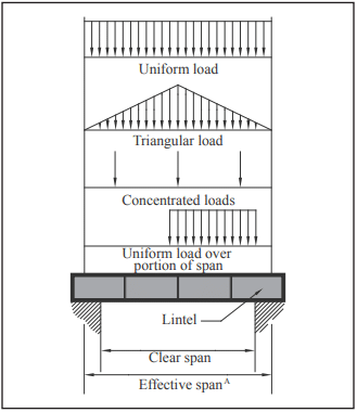
Most of these loads can be separated into the four types illustrated in Figure 1: uniform load acting over the effective span; triangular load with apex at mid-span acting over the effective span; concentrated load; and uniform load acting over a portion of the effective span.
The designer calculates the effects of each individual load and then combines them using superposition to determine the overall effect, typically by assuming the lintel is a simply supported beam.
Figure 1—Typical Lintel Load Components
A Effective span length is the center-to-center distance between supports.
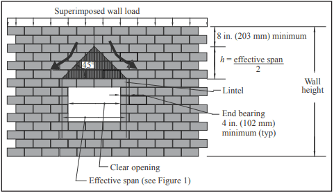
Arching Action
For some configurations, the masonry will distribute applied loads in such a manner that they do not act on the lintel. This is called arching action of masonry. Arching action can be assumed when the following conditions are met (see also Figure 2):
masonry wall laid in running bond,
sufficient wall height above the lintel to permit formation of a symmetrical triangle with base angles of 45° from the horizontal as shown in Figure 2,
at least 8 in. (203 mm) of wall height above the apex of the 45° triangle,
minimum end bearing (4 in. (102 mm) typ.) is maintained,
control joints are not located adjacent to the lintel, and
sufficient masonry on each side of the opening to resist lateral thrust from the arching action.
Figure 2—Arching Action
Lintel Loading
The loads supported by a lintel depend on whether or not arching action can occur. When arching is not present, the lintel self-weight, the full weight of the wall section above the lintel and superimposed loads are considered. Self weight is a uniform load based on lintel weight (see Table 1).
When arching occurs, the wall weight supported by the lintel is taken as the wall weight within the triangular area below the apex (see Figure 2 and Table 2). This triangular load has a base equal to the effective span length of the lintel and a height of half the effective span. Any superimposed roof and floor live and dead loads outside this triangle are neglected, since they are assumed to be distributed to the masonry on either side of the lintel. Loads applied within the triangle need to be considered, however.
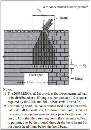
Concentrated loads are assumed to be distributed as illustrated in Figure 3. The load is then resolved onto the lintel as a uniform load, with a magnitude determined by dividing the concentrated load by this length. In most cases, this results in a uniform load acting over a portion of the lintel span.
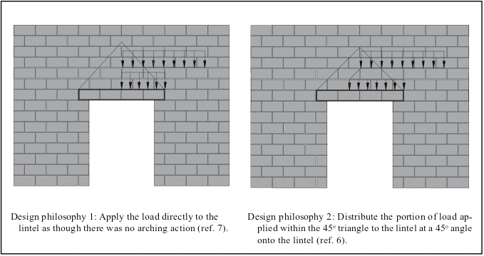
The MSJC (ref. 2) does not address how to apply uniform loads that are applied within the 45° triangle. There are two schools of thought (see Figure 4):
Apply the full uniform load directly to the lintel without further distribution just as though there was no arching for those loads.
Distribute the portions of uniform loads that are applied within the 45o triangle to the lintel. These uniform loads within the 45o triangle may be dispersed and distributed at a 45o angle onto the lintel (ref. 5).
Lintels are required to be designed to have adequate stiffness to limit deflections that would adversely affect strength or serviceability. In addition, the deflection of lintels supporting unreinforced masonry is limited to the clear lintel span divided by 600 to limit damage to the supported masonry (ref. 2).
Table 1—Lintel Weights per Foot, D(lintel), lb/ft (kN/m) (A)
A Face shell mortar bedding. Unit weights: grout = 140 pcf (2,242 kg/m³); lightweight masonry units = 100 pcf (1602 kg/m³); normal weight units = 135 pcf (2,162 kg/m³).
Figure 3—Distribution of Concentrated Load for Running Bond Construction
Figure 4—Methods of Applying Uniform Loads that Occur Within the 45° Triangle
DESIGN TABLES
Tables 3 and 4 present allowable shear and moment, respectively, for various concrete masonry lintels, with various amounts of reinforcement and bottom cover based on a specified compressive strength of masonry, f’m = 1,500 psi (10.3 MPa) and the allowable stress design provisions of the 2011 MSJC (ref. 2a) and the 2012 IBC (ref.1a).
Table 3—Allowable Shear Capacities for Concrete Masonry LintelsA
Table 4
Table 4 continued
DESIGN EXAMPLE
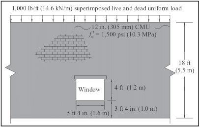
Design a lintel for a 12 in. (305 mm) normal weight concrete masonry wall laid in running bond with vertical reinforcement at 48 in. (1.2 m) o.c. The wall configuration is shown in Figure 5.
Case 1—Arching Action
Check for Arching Action. Determine the height of masonry required for arching action. Assuming the lintel has at least 4 in. (102 mm) bearing on each end, the effective span is:
L = 5.33 + 0.33 = 5.67 ft (1.7 m).
The height of masonry above the lintel necessary for arching to occur in the wall (from Figure 2) is h + 8 in. (203 mm) = L/2 + 8 in. = 3.5 ft (1.1 m). Based on an 8-in. (203-mm) high lintel, there is 18.0 – (3.33 + 4.0 + 0.67) = 10.0 ft (3.0 m) of masonry above the lintel. Therefore, arching is assumed and the superimposed uniform load is neglected.
Design Loads. Because arching occurs, only the lintel and wall dead weights are considered. Lintel weight, from Table 1, for 12 in. (305 mm) normal weight concrete masonry units assuming an 8 in. (203 mm) height is Dlintel = 88 lb/ft (1.3 kN/m).
For wall weight, only the triangular portion with a height of 3.5 ft (1.1 m) is considered. From Table 2, wall dead load is:
Dwall = 63 lb/ft² (3.5 ft) = 221 lb/ft (3.2 kN/m) at the apex.
Maximum moment and shear are determined using simply supported beam relationships. The lintel dead weight is considered a uniform load, so the moment and shear are,
Because the maximum moments for the two loading conditions occur in the same locations on the lintel (as well as the maximum shears), the moments and shears are superimposed and summed:
Lintel Design. From Tables 3 and 4, a 12 x 8 lintel with one No. 4 (M#13) bar and 3 in. (76 mm) or less bottom cover has adequate strength (Mall = 22,356 lb-in. (2.53 kN-m) and Vall = 2,152 lb (9.57 kN)). In this example, shear was conservatively computed at the end of the lintel. However, Building Code Requirements for Masonry Structures (ref. 2) allows maximum shear to be calculated using a distance d/2 from the face of the support.
Case 2—No Arching Action
Using the same example, recalculate assuming a 2 ft (0.6 m) height from the bottom of the lintel to the top of the wall. For ease of construction, the entire 2 ft (0.6 m) would be grouted solid, producing a 24 in. (610 mm) deep lintel.
Because the height of masonry above the lintel is less than 3.5 ft (1.1 m), arching cannot be assumed, and the superimposed load must be accounted for.
Dlintel = 264 lb/ft (3.9 kN/m), from Table 1. Because the lintel is 24 in. (610 mm) deep, there is no additional dead load due to masonry above the lintel.
From Tables 3 and 4, a 12 x 24 lintel with one No. 4 (M#13) reinforcing bar and 3 in. (76 mm) or less bottom cover is adequate (Mall = 122,872 lb-in. (13.88 kN-m) and Vall = 10,256 lb (45.62 kN).
Figure 5—Wall Configuration for Design Example
NOTATIONS
b = width of lintel, in. (mm) Dlintel = lintel dead load, lb/ft (kN/m) Dwall = wall dead load, lb/ft (kN/m) d = distance from extreme compression fiber to centroid of tension reinforcement, in. (mm) f’m = specified compressive strength of masonry, psi (MPa) h = half of the effective lintel span, L/2, ft (m) L = effective lintel span, ft (m) Mall = allowable moment, in.-lb (N⋅m) Mlintel = maximum moment due to lintel dead load, in.-lb (N⋅m) Mmax = maximum moment, in.-lb (N⋅m) Mwall = maximum moment due to wall dead load moment, in.-lb (N⋅m) Vall = allowable shear, lb (N) Vlintel = maximum shear due to lintel dead load, lb (N) Vmax = maximum shear, lb (N) Vwall = maximum shear due to wall dead load, lb (N) Wtotal = total uniform live and dead load, lb/ft (kN/m) w = uniformly distributed load, lb/in. (N/mm)
REFERENCES
International Building Code. International Code Council.
2012 Edition
Building Code Requirements for Masonry Structures. Reported by the Masonry Standards Joint Committee. a. 2011 Edition: TMS 402-11/ACI 530-11/ASCE 5-11
ASD of Concrete Masonry (2012 IBC & 2011 MSJC), TEK 14-07C, Concrete Masonry & Hardscapes Association, 2011.
Weights and Section Properties of Concrete Masonry Assemblies, CMU-TEC-002-23, Concrete Masonry & Hardscapes Association, 2023.
Openings in Concrete Masonry Walls (Part 1), Masonry Chronicles Winter 2008-09, Concrete Masonry Association of California and Nevada, 2009.
When selecting a building enclosure, concrete masonry cavity walls are considered to be one of the best solutions available for all types of buildings. From both an initial cost and life-cycle cost perspective, cavity wall construction is highly regarded as the prime choice in many applications.
Cavity walls typically consist of an inner wythe of concrete masonry units that are tied to an exterior wythe of architectural masonry units. The cavity space between the wythes is normally 2 to 4 ½ in. (51 to 114 mm) wide, easily accommodating rigid board insulation. The two wythes together provide a wall that is highly resistant to wind driven rain, absorbs and reflects sound, provides good thermal performance, and has excellent fire resistance characteristics.
Masonry walls constructed of two or more wythes can technically be classified in one of three ways, depending on how the wythes are designed and detailed. These wall types include composite, noncomposite and veneer assemblies. In noncomposite construction, covered in this TEK, each wythe is connected to the adjacent wythe with metal wall ties, but they are designed such that each wythe individually resists the loads imposed on it. Composite walls are designed so that the wythes act together as a single element to resist structural loads. This requires the masonry wythes to be connected by masonry headers or by a mortar- or grout-filled collar joint and wall ties (see ref. 4). In a veneer wall, the backup wythe is designed as the loadbearing system while the veneer provides a nonloadbearing architectural wall finish that transfers loads to the backup wythe through wall ties (see refs. 5, 6). Although Building Code Requirements for Masonry Structures (ref. 1) defines a cavity wall as a noncomposite masonry wall, the term cavity wall is also commonly used to describe a veneer wall with masonry backup.
This TEK illustrates the design of noncomposite concrete masonry walls based on Building Code Requirements for Masonry Structures (ref. 1), referred to here as the MSJC code. Each wythe of a noncomposite wall system can be designed to accommodate all types of loads, including gravity loads from roofs, walls and floors, as well as lateral loads from wind or earthquakes. The MSJC code design provisions are used to size these masonry walls.
STRUCTURAL DESIGN
The MSJC code includes noncomposite design provisions for both allowable stress design (Chapter 2) and empirical design (Chapter 5). The assumptions and relevant governing equations for each of these design approaches is given in references 2 and 3 respectively.
Concrete masonry cavity walls can be designed as either reinforced or unreinforced walls. For unreinforced design, flexural tensile stresses in masonry are resisted by bond developed between the masonry units and mortar; axial tension is not permitted (ref. 1). If direct axial tension is encountered in a design, reinforcement must be used. In reinforced masonry design, all tension is assumed to be resisted by reinforcement.
Empirical Design
Empirical design can be an expedient approach for typical loadbearing structures subjected to nominal wind loads (basic wind speed ≤ 110 mph, (177 km/h) (MSJC 5.1.2.2) and located in areas of low seismic risk, as it cannot be used for the design of seismic force resisting systems in SDC (Seismic Design Category) B or higher (MSJC 5.1.2.1). Empirical design utilizes prescriptive provisions, outlining criteria such as wall height to thickness ratios, minimum wall thickness and maximum building height.
References 1 and 3 contain maximum length-to-thickness or height-to-thickness ratios for empirically designed walls. When using these ratios for noncomposite multiwythe walls, the total wall thickness is taken as the sum of the nominal thicknesses of each wythe, neglecting the presence of any cavity thickness. Compressive stress is based on the gross cross-sectional area of all wythes, including hollow cells but not including the cavity between the wythes. When floor or roof loads are carried on only one wythe, only the gross cross-sectional area of that wythe is used to check the axial capacity. In addition, these walls must meet the following requirements for wall ties connecting the wythes:
wall ties of wire size W2.8 (3/16 in., MW 18), or metal wire of equivalent stiffness, spaced at a maximum of 24 in. (610 mm) o.c. vertically and 36 in. (914 mm) o.c. horizontally, with at least one wall tie for each 4½ ft² (0.42 m²) of wall area,
walls constructed with hollow units must use rectangular ties,
walls constructed with solid units must use Z-shaped ties with hooks at least 2 in. (51 mm) long,
wall ties may not have drips,
additional ties are required within 12 in. (305 mm) of all openings and must be spaced no more than 3 ft (914 mm) apart around the perimeter of the opening.
Requirements for bonding with joint reinforcement are the same as those for wall ties with the following exceptions: cross wire size may not be smaller than W1.7 (9 gage, MW 11) and the supported wall area per cross wire may not exceed 2⅔ ft² (0.25 m²). In addition, the longitudinal wires must be embedded in mortar.
Allowable Stress Design
Similar to empirical design, MSJC allowable stress design includes prescriptive requirements for bonding wythes of noncomposite walls via wall ties, adjustable ties and joint reinforcement.
For rectangular ties, Z ties (for use with other than hollow units) and ladder or tab-type joint reinforcement, ties or cross wires of joint reinforcement, ties must be placed with a maximum spacing of 36 in. (914 mm) horizontally and 24 in. (610 mm) vertically. The minimum number of ties is one per:
2⅔ ft² (0.25 m²) of wall for wire size W 1.7 (9 gage, MW 11), and
4½ ft² (0.42 m²) of wall for wire size W 2.8 (3/16 in., MW 18).
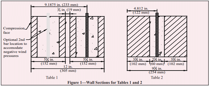
For adjustable ties, one tie must be provided for each 1.77 ft² (0.16 m²) of wall; maximum horizontal and vertical spacing is 16 in. (406 mm); misalignment of bed joints from one wythe to the other may not exceed 1 ¼ in. (31.8 mm); the maximum clearance between connecting parts of the tie is 1/16 in. (1.6 mm); and pintle ties must have at least two pintle legs of wire size W2.8 (3/16 in., MW 18) (see also Figure 1).
For noncomposite masonry walls, the following additional requirements apply.
Collar joints are not to contain headers, or be filled with mortar or grout.
Gravity loads from supported horizontal members are to be resisted by the wythe nearest the center of the span.
Bending moments about the weak axis of the wall and transverse loads are distributed to each wythe according to relative stiffness. This can be determined by: Wi = WT [EmIi/(EmIi+ EmI0)] Wo = WT [EmI0/(EmIi+ EmI0)]
Loads acting parallel to the wall are resisted by the wythe to which they are applied.
The cavity width between the wythes is limited to 4½ in. (114 mm) unless a detailed wall tie analysis is performed.
The following examples illustrate the use of noncomposite masonry employing empirical and allowable stress design methods. Although there are no specific provisions in MSJC for noncomposite wall design using strength design, strength design could be used provided the same load distribution principles as presented for allowable stress design are employed.
Empirical Design Design Example: Design the top story of a two-story noncomposite double wythe masonry wall system supported on continuous footings. Note that the design of the lower story, though not shown, is performed in the same manner, except that the floor live and dead loads from the upper story are also accounted for.
Given:
unsupported wall height
= 10 ft (3.01 m)
superimposed gravity dead load
= 220 plf (3.2 kN/m)
superimposed gravity live load
= 460 plf (6.7 kN/m)
net superimposed uplift from wind
= 120 plf (1.8 kN/m)
wind pressure
= 24 psf (1,149 Pa)
eccentricity of all gravity loads
= 0
f’m
= 1,500 psi (10.3 MPa)
Em
= 1,350 ksi (9,308 MPa)
Wall lateral support requirement: l/t or h/t < 18, so minimum required wall thickness = h/18 = 10 ft (12 in./ft)/18 = 6.7 in. (169 mm)
Try a 4-in. (102 mm) outer wythe and 6-in. (152 mm) inner wythe (providing a total nominal wall thickness of 10 in. (254 mm)), and check allowable axial compressive stress due to dead and live loads (gravity loads are carried by the inner wythe only):
dead:
roof
220 lb/ft
wythe = 10 ft x 26 psf (ref. 8)
260 lb/ft
live:
roof
460 lb/ft
total load:
940 lb/ft (13.7 kN/m)
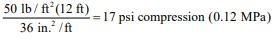
Gross area of 6-in. (152-mm) wythe = 67.5 in.²/ft (ref. 7) fa = 940 lb/ft/(67.5 in.²/ft) = 13.9 psi (0.096 MPa) Fa = 75 psi (0.52 MPa) for Type M or S mortar, 70 psi (0.48 MPa) for Type N mortar (ref. 1) fa < Fa (OK for all mortar types)
Per MSJC code section 5.8.3.1, the net uplift on the roof must be resisted by an anchorage system. Use a bond beam at the top of the inner wythe with vertical reinforcement to the foundation to provide this resistance.
ASD Reinforced Design Example: Given:
unsupported wall height
= 18 ft (5.5 m)
wind load, w
= 36 psf (1,724 Pa)
net roof uplift at top of wall
= 400 plf (5.8 kN/m) )
eccentricity of all vertical loads
= 0
f’m
= 1,500 psi (0.0718 MPa )
unit density
= 115 pcf (1,842 kg/m³)
Grade 60 reinforcement
Note: The 36 psf (1,724 Pa) wind load is much higher than is generally applicable when using empirical design.
Design the inside wythe first, as it must resist the uplift in addition to the flexural loads. Try two 6-in. (152 mm) wythes with No. 5 (M #16) reinforcement at 32 in. (813 mm) o.c.
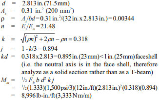
Determine reinforcement needed for uplift at midheight: uplift = 400 lb/ft – 34 lb/ft² (18 ft/2) = 94 lb/ft (1.37 kN/m) (ref. 8) reinforcement needed = [(94 lb/ft)(32 in.)/(12 in./ft)]/[1.333(24,000 psi)] = 0.0078 in.² As available for flexure = 0.31 – 0.0078 = 0.3022 in.² Ms = FsAsjd = 1.333 (24,000 psi) (0.3022 in.²)(0.894)(2.813 in.) = 24,313 lb-in. for 32 in. width = 9,117 lb-in./ft (3,378 N⋅m/m) > 8,996 lb-in./ft (3,333 N⋅m/m), therefore Mm controls
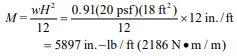
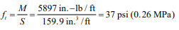
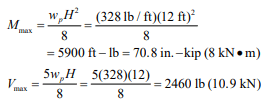
Determine applied moment: Since the wythes are identical, each would carry ½ the lateral load or ½ (36 psf) = 18 psf (124 kPa) Mmax = wl²/8 = (18 psf)(18 ft)²(12 in./ft)/8 = 8,748 lb-in./ft (3,241 N⋅m/m) < 8,996 lb-in./ft (3,333 N⋅m/m) OK
A quick check of the outside wythe shows that the same reinforcement schedule will work for it as well. Therefore, use two 6-in. (152-mm) wythes with No. 5 (M #16) vertical reinforcement at 32 in. (813 mm) o.c.
This wall could be designed using an unreinforced 4-in. (102 mm) outside wythe and a reinforced 8-in. (203-mm) inside wythe, with lateral loads distributed to each wythe according to the uncracked stiffness per MSJC section 1.9.2. Experience has shown, however, that the design would be severely limited by the capacity of the unreinforced outside wythe. Additionally, such a design could be used only in SDC A or B since 4-in. (102 mm) concrete masonry does not have cores large enough to reinforce.
Another alternative would be to design this system treating the 4 in. (102 mm) outer wythe as a nonloadbearing veneer. Designing this wall as a 4-in. (102 mm) veneer with an 8-in. (203 mm) reinforced structural backup wythe would result in No. 5 bars at 16 in. (M #16 at 406 mm) on center. This is the same amount of reinforcement used in the example above (two 6-in. (152 mm) wythes with No. 5 (M #16) at 32 in. (813 mm) on center). However, because the 6-in. (152 mm) units have smaller cores, 30% less grout is required.
The design using two 6-in. (152-mm) reinforced wythes has the following advantages over veneer with structural backup:
no limitation on SDC as when a veneer or an unreinforced outer wythe is used,
no limitation on wind speed as with a veneer,
equal mass on both sides of the wall permitting the use of the prescriptive energy tables for integral insulation, and
the flexibility of using units with different architectural finishes on each side.
NOMENCLATURE
As = effective cross-sectional area of reinforcement, in.²(mm²) b = width of section, in. (mm) d = distance from extreme compression fiber to centroid of tension reinforcement, in. (mm) Em = modulus of elasticity of masonry, psi (MPa) Es = modulus of elasticity of steel, psi (MPa) Fa = allowable compressive stress due to axial load only, psi (kPa) Fb = allowable compressive stress due to flexure only, psi (kPa) Fs = allowable tensile or compressive stress in reinforcement, psi (kPa) Fv = allowable shear stress in masonry, psi (MPa) fa = calculated compressive stress in masonry due to axial load only, psi (kPa) f’m = specified compressive strength of masonry, psi (kPa) h = effective height, in. (mm) fv = calculated shear stress in masonry, psi (MPa) Ii = average moment of inertia of inner wythe, in.4/ft (m4/m) Io = average moment of inertia of outer wythe, in.4/ft (m4/m) j = ratio of distance between centroid of flexural compressive forces and centroid of tensile forces to depth d k = ratio of distance between compression face of wall and neutral axis to depth d l = clear span between supports, in. (mm) M = moment at the section under consideration, in.-lb/ft (N⋅m/m) Mm = flexural capacity (resisting moment) when masonry controls, in.-lb/ft (N⋅m/m) Mmax = maximum moment at the section under consideration, in.-lb/ft (N⋅m/m) Ms = flexural capacity (resisting moment) when reinforcement controls, in.-lb/ft (N⋅m/m) t = nominal thickness of a member, in. (mm) Vmax = maximum shear at the section under consideration, lb/ft (kN/m) Wi = percentage of transverse load on inner wythe Wo = percentage of transverse load on outer wythe WT = total transverse load w = wind pressure, psf (Pa) ρ = reinforcement ratio
REFERENCES
Building Code Requirements for Masonry Structures, ACI 530-02/ASCE 5-02/TMS 402-02. Reported by the Masonry Standards Joint Committee, 2002.
ASD of Concrete Masonry (2012 IBC & 2011 MSJC), TEK 14-07C, Concrete Masonry & Hardscapes Association, 2004.
Empirical Design of Concrete Masonry Walls, TEK 1408B, Concrete Masonry & Hardscapes Association, 2003
Structural Design of Unreinforced Composite Masonry, TEK 16-02B, Concrete Masonry & Hardscapes Association, 2001.
Reinforced composite concrete masonry walls can provide geometric diversity. Composite walls consist of multiple wythes of masonry connected such that they act as a single structural member. There are prescriptive requirements in both the International Building Code (ref. 1) and Building Code Requirements for Masonry Structures (ref. 2) for connecting the wythes. General information on composite walls is included in TEK 16-01A, Multi-Wythe Concrete Masonry Walls (ref. 3) which is intended to be used in conjunction with this TEK.
Reinforced composite masonry walls are designed by the same procedures as all reinforced masonry walls. They must meet the same construction requirements for reinforcing placement, tolerances, grout placement, and workmanship as all reinforced concrete masonry walls.
Although composite walls can be reinforced or unreinforced, this TEK discusses the requirements for reinforced composite walls. Unreinforced composite walls are discussed in TEK 1602B, Structural Design of Unreinforced Composite Masonry (ref. 4).
DESIGN CONSIDERATIONS
Composite masonry is defined as “multicomponent masonry members acting with composite action” (ref. 2). For a multiwythe wall section to act compositely, the wythes of masonry must be adequately connected. Provisions for properly bonding the wythes are discussed in TEK 16-01A. When wall ties are used, the collar joint – the vertical space between the two wythes of masonry – must be filled solid with grout or mortar (refs. 1, 2). However, when reinforcement is placed in the collar joint, grout must be used to fill the collar joint.
Considerations When Choosing a Cross Section
Unlike single wythe walls, where the geometric cross section is set by the product as manufactured, the cross section of a composite wall is determined by the combination of units and collar joint which can theoretically be any thickness. Practically speaking, code, structural and architectural requirements will narrow the options for wall sections. In addition to structural capacity, criteria specific to cross-section selection for reinforced composite walls include:
• location of reinforcement in collar joint or in unit cores;
• collar joint thickness;
• unit selection for each wythe.
Structural Reinforcement Location
The engineer has the option of locating the structural reinforcing steel in the collar joint or in one or both wythes. While there is no direct prohibition against placing reinforcement in both the collar joint and the unit cores, practically speaking there is rarely a structural reason to complicate the cross section with this configuration.
With some units, it may be easier to install reinforcement in the collar joint, such as when both wythes are solid or lack sufficient cell space for reinforcing bars. Depending on the units selected, the collar joint may or may not provide the option to center the reinforcement within the wall cross section. For example, when the units are not the same thickness, the collar joint does not necessarily span the center of the section.
Conversely, if off-set reinforcing is preferred, perhaps to accommodate unbalanced lateral loads, it may be benefi cial to place the vertical bars in the unit cores. Placing reinforcement in the unit cores permits a thinner collar joint and possibly a thinner overall cross-section. Unit cores may provide a larger and less congested opening for the reinforcing bars and grout since the collar joint will be crossed with connecting wall ties. There is also the possibly that for a given geometry, centered reinforcement does end up in a core space.
Reinforcement can also be placed in the cells of each wythe, providing a double curtain of steel to resist lateral loads from both directions, as in the case of wind pressure and suction.
Collar Joint Width
There are no prescriptive minimums or maximums explicit to collar joint thickness in either Building Code Requirements for Masonry Structures or the International Building Code, however there are some practical limitations for constructability and also code compliance in reinforcing and grouting that effect the collar joint dimension. Many of these are covered in TEK 16-01A but a few key points from the codes that are especially relevant for reinforced composite masonry walls included below:
Wall tie length: Noncomposite cavity walls have a cavity thickness limit of 4½ in. (114 mm) unless a wall tie analysis is performed. There is no such limitation on width for filled collar joints in composite construction since the wall ties can be considered fully supported by the mortar or grout, thus eliminating concern about local buckling of the ties. Practically speaking, since cavity wall construction is much more prevalent, the availability of standard ties may dictate collar joint thickness maximums close to 4½ in. (114 mm).
Pour and lift height: Since the collar joint must be fi lled, the width of the joint infl uences the lift height. Narrow collar joints may lead to low lift or pour heights which could impact cost and construction schedule. See Table 1 in TEK 03-02A, Grouting Concrete Masonry Walls (ref. 5) for more detailed information.
Course or fine grout: Codes require a minimum clear distance of ¼-in. (6.3-mm) for fine grout and ½-in. (13-mm) for coarse grout between reinforcing bars and any face of the masonry unit.
Course or fine grout: Codes require a minimum clear distance of ¼-in. (6.3-mm) for fine grout and ½-in. (13-mm) for coarse grout between reinforcing bars and any face of the masonry unit.
Grout or mortar fill: Although codes permit collar joints to be filled with either mortar or grout, grout is preferred because it helps ensure complete filling of the collar joint without creating voids. Note that collar joints less than ¾ in. (19 mm), unless otherwise required, are to be filled with mortar as the wall is built. Increasing the slump of the mortar to achieve a solidly filled joint is preferred. This effectively requires a ¾-in. (19-mm) minimum on collar joints with structural reinforcing since it is also a code requirement that reinforcing bars be placed in grout, not mortar.
Reinforcing bar diameter: The reinforcing bar diameter cannot exceed one-half the least clear dimension of the collar joint.
Horizontal bond beams: Bond beams may be required to meet prescriptive code requirements such as seismic detailing. The collar joint then must be wide enough to accommodate the horizontal and vertical reinforcement along with the accompanying clearances for embedment in grout.
Unit Selection for Each Wythe
Aesthetic criteria may play a primary role in unit selection for reinforced composite walls. Designing the composite wall to match modular dimensions may make detailing of interfaces much easier. Window and door frames, foundations, connectors and other accessories may coordinate better if typical masonry wall thicknesses are maintained. Additional criteria that influence the selection of units for reinforced composite walls include:
Size and number of reinforcing bars to be used and the cell space required to accommodate them.
Cover requirements (see ref. 6) may come into play when reinforcement is placed in the cells off-center. Cover requirements could affect unit selection, based on the desired bar placement; face shell thickness and cell dimensions.
If double curtains of vertical reinforcement are used, it is preferable to use units of the same thickness to produce a symmetrical cross section.
Structural Considerations
Some structural considerations were addressed earlier in this TEK during the discussion of cross section determination. Since reinforced composite masonry by definition acts as one wall to resist loads, the design procedures are virtually the same as for all reinforced masonry walls. TEK 14-07C, ASD of Concrete Masonry (2012 IBC & 2011 MSJC) (ref. 7) details design procedures. A few key points should be stressed, however:
Analysis: Empirical design methods are not permitted to be used for reinforced multiwythe composite masonry walls.
Section properties: Section properties must be calculated using the transformed section method described in TEK 1601A (ref. 3).
Shear stresses: Shear stress in the plane of interface between wythes and collar joint is limited to 5 psi (34.5 kPa) for mortared collar joints and 10 psi (68.9 kPa) for grouted collar joints.
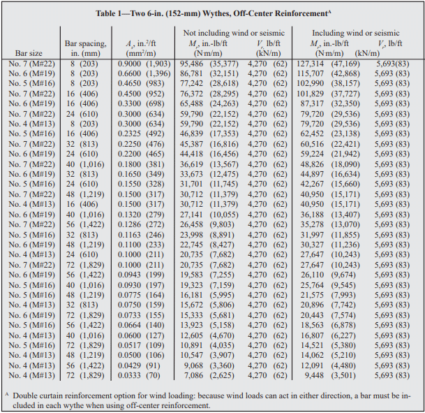
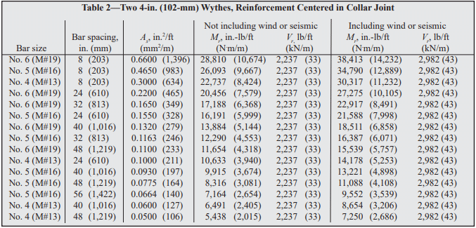
DESIGN TABLES
Design tables for select reinforced composite walls are included below. The tables include maximum bending moments and shear loads that can be sustained without exceeding the allowable stresses defined in the International Building Code and Building Code Requirements for Masonry Structures. These can be compared to Tables 1 and 2 of TEK 14-19B, ASD Tables for Reinforced CM Walls (2012 IBC & 2011 MSJC) (ref. 8) for wall subjected to uniform lateral loads to ensure the wall under consideration is not loaded beyond its design capacity. The examples are based on the following criteria:
The examples are based on the following criteria:
• Allowable stresses:
In addition to these tables, it is important to check all code requirements governing grout space dimensions and maximum reinforcement size to ensure that the selected reinforcing bar is not too large for the collar joint. The designer must also check shear stress at the unit/grout interface to ensure it does not exceed the code allowable stress for the design loading.
Table 2—Two 4-in. (102-mm) Wythes, Reinforcement Centered in Collar Joint
CONSTRUCTION AND DETAILING REQUIREMENTS
With composite wall construction, the two masonry wythes are not required to be built at the same time unless the collar joint is less than ¾ in. (19 mm), as the code mandates that those collar joints be mortared as the wall is built. Practically speaking it is easier to build both wythes at the same time to facilitate placing either the grout or the mortar in the collar joint at the code required pour heights.
It can be more complex to grout composite walls. Consider that a composite wall may have requirements to grout the collar joint for the full wall height and length but the cores of the concrete masonry units may only need to be partially grouted at reinforcing bar locations. Installing reinforcement and grout in the collar joint space can also be more time-consuming because of congestion due to the wall ties.
Nonmodular composite wall sections may cause diffi culty at points where they interface with modular elements such as window and door frames, bonding at corners and bonding with modular masonry walls.
NOTATIONS
As = effective cross-sectional area of reinforcement, in.²/ft (mm²/m) d = distance from extreme compression fiber to centroid of tension reinforcement, in. (mm) Eg = modulus of elasticity of grout, psi (MPa) Em = modulus of elasticity of masonry in compression, psi (MPa) Es = modulus of elasticity of steel, psi (MPa) Fb = allowable compressive stress due to flexure only, psi (MPa) Fs = allowable tensile or compressive stress in reinforcement, psi (MPa) Fv = allowable shear stress in masonry, psi (MPa) f’g = specified compressive strength of grout, psi (MPa) f’m = specified compressive strength of masonry, psi (MPa) Mr = resisting moment of wall, in.-lb/ft (kNm/m) Vr = resisting shear of wall, lb/ft (kN/m)
REFERENCES
International Building Code 2003. International Code Council, 2003.
Building Code Requirements for Masonry Structures, ACI 530-05/ASCE 5-05/TMS 402-05. Reported by the Masonry Standards Joint Committee, 2005.
The 1999 Building Code Requirements for Masonry Structures, ACI 530/ASCE 5/TMS 402 (ref. 1), was the first masonry code in the United States to include general design provisions for prestressed masonry. Prestressing masonry is a process whereby internal compressive stresses are introduced to counteract tensile stresses resulting from applied loads. Compressive stresses are developed within the masonry by tensioning a steel tendon, which is anchored to the top and bottom of the masonry element (see Figure 1). Post-tensioning is the primary method of prestressing, where the tendons are stressed after the masonry has been placed. This TEK focuses on the design of concrete masonry walls constructed with vertical post-tensioned tendons.
Advantages
Prestressing has the potential to increase the flexural strength, shear strength and stiffness of a masonry element. In addition to increasing the strength of an element, prestressing forces can also close or minimize the formation of some cracks. Further, while research (refs. 14, 15) indicates that ductility and energy dissipation capacity are enhanced with prestressing, Building Code Requirements for Masonry Structures (ref. 1) conservatively does not take such performance into account.
Post-tensioned masonry can be an economical alternative to conventionally reinforced masonry. One major advantage of prestressing is that it allows a wall to be reinforced without the need for grout. Also, the number of prestressing tendons may be less than the number of reinforcing bars required for the same flexural strength.
Post-tensioning masonry is primarily applicable to walls, although it can also be used for beams, piers, and columns. Vertical post-tensioning is most effective for increasing the structural capacity of elements subjected to relatively low axial loads. Structural applications include loadbearing, nonloadbearing and shear walls of tall warehouses and gymnasiums, and commercial buildings, as well as retaining walls and sound barrier walls. Post-tensioning is also an option for strengthening existing walls.
Figure 1—Schematic of Typical Post-Tensioned Wall
MATERIALS
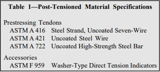
Post-tensioned wall construction uses standard materials: units, mortar, grout, and perhaps steel reinforcement. In addition, post-tensioning requires tendons, which are steel wires, bars or strands with a higher tensile strength than conventional reinforcement. Manufacturers of prestressing tendons must supply stress relaxation characteristics for their material if it is to be used as a prestressing tendon. Specifications for those materials used specifically for post-tensioning are given in Table 1. Other material specifications are covered in references 9 through 12. Construction is covered in Post-Tensioned Concrete Masonry Wall Construction, TEK 03-14 (ref. 3).
Table 1—Post-Tensioned Material Specifications
CORROSION PROTECTION
As with conventionally reinforced masonry structures, Building Code Requirements for Masonry Structures (ref. 1) mandates that prestressing tendons for post-tensioned masonry structures be protected against corrosion. As a minimum, the prestressing tendons, anchors, couplers and end fittings in exterior walls exposed to earth or weather must be protected. All other walls exposed to a mean relative humidity exceeding 75% must also employ some method of corrosion abatement. Unbonded tendons can be protected with galvanizing, epoxy coating, sheathing or other alternative method that provides an equivalent level of protection. Bonded tendons are protected from corrosion by the corrugated duct and prestressing grout in which they are encased.
DESIGN LOADS
As for other masonry structures, minimum required design loads are included in Minimum Design Loads for Buildings and Other Structures, ASCE 7 (ref. 5), or the governing building codes. If prestressing forces are intended to resist lateral loads from earthquake, a factor of 0.9 should be applied to the strength level prestress forces (0.6 for allowable stress design) as is done with gravity loads.
STRUCTURAL DESIGN
The design of post-tensioned masonry is based on allowable stress design procedures, except for laterally restrained tendons which use a strength design philosophy. Building Code Requirements for Masonry Structures (ref. 1) prescribes allowable stresses for unreinforced masonry in compression, tension and shear, which must be checked against the stresses resulting from applied loads.
The flexural strength of post-tensioned walls is governed by either the flexural tensile stress of the masonry (the flexural stress minus the post-tensioning and dead load stress), the masonry compressive stress, the tensile stress within the tendon, the shear capacity of the masonry or the buckling capacity of the wall.
Masonry stresses must be checked at the time of peak loading (independently accounting for both short-term and long-term losses), at the transfer of post-tensioning forces, and during the jacking operation when bearing stresses may be exceeded. Immediately after transfer of the post-tensioning forces, the stresses in the steel are the largest because long-term losses have not occurred. Further, because the masonry has had little time to cure, the stresses in the masonry will be closer to their capacity. Once long-term losses have transpired, the stresses in both the masonry and the steel are reduced. The result is a coincidental reduction in the effective capacity due to the prestressing force and an increase in the stresses the fully cured masonry can resist from external loads.
Effective Prestress
Over time, the level of prestressing force decreases due to creep and shrinkage of the masonry, relaxation of the prestressing tendons and potential decreases in the ambient temperature. These prestressing losses are in addition to seating and elastic shortening losses witnessed during the prestressing operation. In addition, the prestressing force of bonded tendons will decrease along the length of the tendon due to frictional losses. Since the effective prestressing force varies over time, the controlling stresses should be checked at several stages and loading conditions over the life of the structure.
The total prestress loss in concrete masonry can be assumed to be approximately 35%. At the time of transfer of the prestressing force, typical losses include: 1% seating loss + 1% elastic shortening = 2%. Additional losses at service loads and moment strength include:
relaxation
3%
temperature
10%
creep
8%
CMU shrinkage
7%
contingency
5%
total
33%
Prestress losses need to be estimated accurately for a safe and economical structural design. Underestimating losses will result in having less available strength than assumed. Overestimating losses may result in overstressing the wall in compression.
Effective Width
In theory, a post-tensioning force functions similarly to a concentrated load applied to the top of a wall. Concentrated loads are distributed over an effective width as discussed in the commentary on Building Code Requirements for Masonry Structures (ref. 1). A general rule-of-thumb is to use six times the wall thickness as the effective width.
Elastic shortening during post-tensioning can reduce the stress in adjacent tendons that have already been stressed. Spacing the tendons further apart than the effective width theoretically does not reduce the compressive stress in the effective width due to the post-tensioning of subsequent tendons. The applied loads must also be consolidated into the effective width so the masonry stresses can be determined. These stresses must be checked in the design stage to avoid overstressing the masonry.
Flexure
Tensile and compressive stresses resulting from bending moments applied to a section are determined in accordance with conventional elastic beam theory. This results in a triangular stress distribution for the masonry in both tension and compression. Maximum bending stress at the extreme fibers are determined by dividing the applied moment by the section modulus based on the minimum net section.
Net Flexural Tensile Stress
Sufficient post-tensioning force needs to be provided so the net flexural tensile stress is less than the allowable values. Flexural cracking should not occur if post-tensioning forces are kept within acceptable bounds. Flexural cracking due to sustained post-tensioning forces is believed to be more severe than cracking due to transient loading. Flexural cracks due to eccentric post-tensioning forces will remain open throughout the life of the wall, and may create problems related to water penetration, freeze-thaw or corrosion. For this reason, Building Code Requirements for Masonry Structures (ref. 1) requires that the net flexural tensile stress be limited to zero at transfer of the post-tensioning force and for service loadings with gravity loads only.
Axial Compression
Compressive stresses are determined by dividing the sum of the post-tensioning and gravity forces by the net area of the section. They must be less than the code prescribed (ref. 1) allowable values of axial compressive stress.
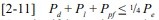
Walls must also be checked for buckling due to gravity loads and post-tensioning forces from unrestrained tendons. Laterally restrained tendons can not cause buckling; therefore only gravity compressive forces need to be checked for buckling in walls using laterally restrained tendons. Restraining the tendons also ensures that the tendons do not move laterally in the wall when the masonry deflects. The maximum compressive force that can be applied to the wall based upon ¼ buckling is Pe, per equation 2-11 of Building Code Requirements for Masonry Structures (ref. 1).
Combined Axial and Flexural Compressive Stress
Axial compressive stresses due to post-tensioning and gravity forces combine with flexural compressive stresses at the extreme fiber to result in maximum compressive stress. Conversely, the axial compressive stresses combine with the flexural tensile stresses to reduce the absolute extreme fiber stresses. To ensure the combination of these stresses does not exceed code prescribed allowable stresses, a unity equation is checked to verify compliance. Employing this unity equation, the sum of the ratios of applied-to-allowable axial and flexural stresses must be less than one. Unless standards (ref. 5) limit its use, an additional one-third increase in allowable stresses is permitted for wind and earthquake loadings, as is customary with unreinforced and reinforced masonry. Further, for the stress condition immediately after transfer of the post-tensioning force, a 20% increase in allowable axial and bending stresses is permitted by Building Code Requirements for Masonry Structures (ref. 1).
Shear
As with all stresses, shear stresses are resisted by the net area of masonry, and the wall is sized such that the maximum shear stress is less than the allowable stress. In addition, the compressive stress due to post-tensioning can be relied on to increase allowable shear stresses in some circumstances.
Post-Tensioning Tendons
The stress in the tendons is limited (ref. 1) such that:
the stress due to the jacking force does not exceed 0.94fpy, 0.80fpu, nor that recommended by the manufacturer of the tendons or anchorages,
the stress immediately after transfer does not exceed 0.82fpy nor 0.74fpu, and
the stress in the tendons at anchorages and couplers does not exceed 0.78fpy nor 0.70fpu.
DETERMINATION OF POST-TENSIONING FORCES
Case (a) after prestress losses and at peak loading:
Assuming that the moment, M, due to wind or earthquake loadings is large relative to the eccentric load moment, the critical location will be at the mid-height of the wall for simply-supported walls, and the following equations apply (bracketed numbers are the applicable Building Code Requirements for Masonry Structures (ref. 1) equation or section numbers):
The 1.33 factor in Equation [2-10] represents the one- third increase in allowable stress permitted for wind and earthquake loadings. If the moment, M, is a result of soil pressures (as is the case for retaining walls), the 1.33 factor in Equation [2-10] must be replaced by 1.00.
Note that if the tendons are laterally restrained, Ppf should not be included in Equation [2-11].
(under the load combination of prestressing force and dead load only)
Additional strength design requirements for laterally restrained tendons:
Equation 4-3 above applies to members with uniform width, concentric reinforcement and prestressing tendons and concentric axial load. The nominal moment strength for other conditions should be determined based on static moment equilibrium equations.
Case (b) at transfer of post-tensioning:
Assuming that vertical live loads are not present during post-tensioning, the following equations apply. The worst case is at the top of the wall where post-tensioning forces are applied.
For cantilevered walls, these equations must be modified to the base of the wall.
If the eccentricity of the live load, Pl, is small, neglecting the live load in Equation [2-10] may also govern.
Case (c) bearing stresses at jacking:
Bearing stresses at the prestressing anchorage should be checked at the time of jacking. The maximum allowable bearing stress at jacking is 0.50f’mi per Building Code Requirements for Masonry Structures (ref. 1) section 4.9.4.2.
DESIGN EXAMPLE
Design a simply-supported exterior wall 12 ft (3.7 m) high for a wind load of 15 psf (0.72 kPa). The wall is constructed of concrete masonry units complying with ASTM C 90 (ref. 6). The units are laid in a full bed of Type S Portland cement lime mortar complying with ASTM C 270 (ref. 7). The specified compressive strength of the masonry (f’m) is 1,500 psi (10.3 MPa). The wall will be post-tensioned with 7/16 in. (11 mm) diameter laterally restrained tendons when the wall achieves a compressive strength of 1,250 psi (8.6 MPa). Axial load and prestress are concentric.
Given: 8 in. (203 mm) CMU tf = 1.25 in. (32 mm) f’m = 1,500 psi (10.3 MPa) f’mi = 1,250 psi (8.6 MPa) Fbt = 25 psi (0.17 MPa) (Type S Portland cement/lime mortar) fpy = 100 ksi (690 MPa) (bars) fpu = 122 ksi (840 MPa) Aps = 0.14 in² (92 mm²) Es = 29 x 106 psi (200 GPa) Em = 900 f’m = 1.35 x 10⁶ psi (9,300 MPa) n = Es/Em = 21.5 d = 7.625/2 in. = 3.81 in. (97 mm) (tendons placed in the center of the wall) unit weight of CMU wall = 39 psf (190 kg/m²) (ref. 13)
Maximum tendon stresses: Determine governing stresses based on code limits (ref. 1):
At jacking:
0.94 fpy = 94.0 ksi (648 MPa)
0.80 fpu = 97.6 ksi (673 MPa)
At transfer:
0.82 fpy = 82.0 ksi (565 MPa)
0.74 fpu = 90.3 ksi (623 MPa)
At service loads:
0.78 fpy = 78.0 ksi (538 MPa) ⇒ governs
0.70 fpu = 85.4 ksi (589 MPa)
Because the tendon’s specified tensile strength is less than 150 ksi (1,034 MPa), fps = fse (per ref. 1 section 4.5.3.3.4).
Prestress losses: Assume 35% total loss (as described in the Effective Prestress section above).
Tendon forces: Determine the maximum tendon force, based on the governing tendon stress determined above for each case of jacking, transfer and service. At transfer, include 2% prestress losses. At service, include the full 35% losses. Tendon capacity at jacking = 0.94 fpyAps = 13.3 kips (59 kN) Tendon capacity at transfer = 0.82 fpyAps A x 0.98 = 11.4 kips (51 kN) (including transfer losses) Tendon capacity at service = 0.78 fpyAps A x 0.65 = 7.2 kips (32 kN) (including total losses)
Try tendons at 48 in. (1,219 mm) on center (note that this tendon spacing also corresponds to the maximum effective prestressing width of six times the wall thickness).
Determine prestressing force, based on tendon capacity determined above: at transfer: Ppi = 11.4 kips/4 ft = 2,850 lb/ft (41.6 kN/m) at service: Ppf = 7.2 kips/4 ft = 1,800 lb/ft (26.3 kN/m)
Wall section properties: (ref. 8) 8 in. (203 mm) CMU with full mortar bedding: An = 41.5 in.²/ft (87,900 mm²/m) I = 334 in.4/ft (456 x 106 mm4/m) S = 87.6 in.³/ft (4.71 x 106 mm³/m) r = 2.84 in. (72.1 mm)
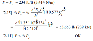
At service loads: At service, the following are checked: combined axial compression and flexure using the unity equation (equation 2-10); net tension in the wall; stability by ensuring the compressive load does not exceed one-fourth of the buckling load, Pe, and shear and moment strength.
Check combined axial compression and flexure:
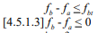
Check tension for load combination of prestress force and dead load only (per ref. 1 section 4.5.1.3):
Check stability: Because the tendons are laterally restrained, the prestressing force, Ppf, is not considered in the determination of axial load ( per ref. 1 section 4.5.3.2), and the wall is not subject to live load in this case, so equation 2-11 reduces to:
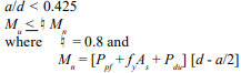
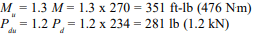
Check moment strength: Building Code Requirements for Masonry Structures section 4.5.3.3 includes the following criteria for moment strength of walls with laterally restrained tendons:
In addition, the compression zone must fall within the masonry, so a < tf.
where 1.3 and 1.2 are load factors for wind and dead loads, respectively.
At transfer: Check combined axial compression and flexure using the unity equation (equation 2-10) and net tension in the wall.
Check tension for load combination of prestress force and dead load only (per ref. 1 section 4.5.1.3):
Therefore, use 7/16 in. (11 mm) diameter tendons at 48 in. (1,219 mm) o.c. Note that although wall design is seldom governed by out-of-plane shear, the shear capacity should also be checked.
NOTATIONS
An net cross-sectional area of masonry section, in.² (mm²) Aps threaded area of post-tensioning tendon, in.² (mm²) As cross-sectional area of mild reinforcement, in.² (mm²) a depth of an equivalent compression zone at nominal strength, in. (mm) b width of section, in. (mm) d distance from extreme compression fiber to centroid of prestressing tendon, in. (mm) Es modulus of elasticity of prestressing steel, psi (MPa) Em modulus of elasticity of masonry, psi (MPa) ed eccentricity of dead load, in. (mm) el eccentricity of live load, in. (mm) ep eccentricity of post-tensioning load, in. (mm) Fa allowable masonry axial compressive stress, psi (MPa) Fai allowable masonry axial compressive stress at transfer, psi (MPa) Fb allowable masonry flexural compressive stress, psi (MPa) Fbi allowable masonry flexural compressive stress at transfer, psi (MPa) Fbt allowable flexural tensile strength of masonry, psi (MPa) fa axial stress after prestress loss, psi (MPa) fai axial stress at transfer, psi (MPa) fb flexural stress after prestress loss, psi (MPa) fbi flexural stress at transfer, psi (MPa) f’m specified compressive strength of masonry, psi (MPa) f’mi specified compressive strength of masonry at time of transfer of prestress, psi (MPa) fps stress in prestressing tendon at nominal strength, psi (MPa) fpu specified tensile strength of prestressing tendon, ksi (MPa) fpy specified yield strength of prestressing tendon, ksi (MPa) fse effective stress in prestressing tendon after all pre-stress losses have occurred, psi (MPa) fy specified yield strength of steel for reinforcement and anchors, psi (MPa) h masonry wall height, in. (mm) I moment of inertia of net wall section of extreme fiber tension or compression, in.4/ft (mm4/m) M moment due to lateral loads, ft-lb (N⋅m) Mn nominal moment strength, ft-lb (N⋅m) Mu factored moment due to lateral loads, ft-lb (N⋅m) n modular ratio of prestressing steel and masonry (Es/Em) Pd axial dead load, lb/ft (kN/m) Pdu factored axial dead load, lb/ft (kN/m) Pe Euler buckling load, lb/ft (kN/m) Pl axial live load, lb/ft (kN/m) Plu factored axial live load, lb/ft (kN/m) Ppi prestress force at transfer, lb/ft (kN/m) Ppf prestress force including losses, lb/ft (kN/m) r radius of gyration for net wall section, in. (mm) S section modulus of net cross-sectional area of the wall, in.³ /ft (mm³/m) tf face shell thickness of concrete masonry, in. (mm) w applied wind pressure, psf (kPa) ¤ strength reduction factor = 0.8
REFERENCES
Building Code Requirements for Masonry Structures, ACI 530-02/ASCE 5-02/TMS 402-02. Reported by the Masonry Standards Joint Committee, 2002.
Building Code Requirements for Structural Concrete, ACI 318-99. Detroit, MI: American Concrete Institute, Revised 1999.
Construction of Post-Tensioned Concrete Masonry Walls, TEK 03-14. Concrete Masonry & Hardscapes Association, 2002.
International Building Code. International Code Council, 2000.
Minimum Design Loads for Buildings and Other Structures, ASCE 7-98, American Society of Civil Engineers, 1998.
Standard Specification for Loadbearing Concrete Masonry Units, ASTM C 90-01a. American Society for Testing and Materials, 2001.
Standard Specification for Mortar for Unit Masonry, ASTM C 270-01. American Society for Testing and Materials, 2001.
Weights and Section Properties of Concrete Masonry Assemblies, CMU-TEC-002-23, Concrete Masonry & Hardscapes Association, 2023.
Concrete Masonry Unit Shapes, Sizes, Properties, and Specifications, CMU-TEC-001-23, Concrete Masonry & Hardscapes Association, 2023.
Mortars for Concrete Masonry, TEK 09-01A. Concrete Masonry & Hardscapes Association, 2001.
Grout for Concrete Masonry, TEK 09-04. Concrete Masonry & Hardscapes Association, 2005.
Steel for Concrete Masonry Reinforcement, TEK 12-04D. Concrete Masonry & Hardscapes Association, 1998.
Weights and Section Properties of Concrete Masonry Assemblies, CMU-TEC-002-23, Concrete Masonry & Hardscapes Association, 2023.
Schultz, A.E., and M.J. Scolforo, An Overview of Prestressed Masonry, TMS Journal, Vol. 10, No. 1, August 1991, pp. 6-21.
Schultz, A.E., and M.J. Scolforo, Engineering Design Provisions for Prestressed Masonry, Part 1: Masonry Stresses, Part 2: Steel Stresses and Other Considerations, TMS Journal, Vol. 10, No. 2, February 1992, pp. 29-64.
Standard Specification for Steel Strand, Uncoated Seven-Wire for Prestressed Concrete, ASTM A 416-99. American Society for Testing and Materials, 1999.
Standard Specification for Uncoated Stress-Relieved Steel Wire for Prestressed Concrete, ASTM A 421-98a. American Society for Testing and Materials, 1998.
Standard Specification for Uncoated High-Strength Steel Bar for Prestressed Concrete, ASTM A 722-98. American Society for Testing and Materials, 1998.
Standard Specification for Compressible-Washer-Type Direct Tension Indicators for Use with Structural Fasteners, ASTM F 959-01a. American Society for Testing and Materials, 2001.
The combination of concrete masonry and steel reinforcement provides a strong structural system capable of resisting large compressive and flexural loads. Reinforced masonry structures have significantly higher flexural strength and ductility than similarly configured unreinforced structures and provide greater reliability in terms of expected load carrying capacity at failure.
Concrete masonry elements can be designed using several methods in accordance with the International Building Code (IBC, ref. 1) and, by reference, Building Code Requirements for Masonry Structures (MSJC Code, ref. 2): allowable stress design, strength design, direct design, empirical design, or prestressed masonry. The design tables in this TEK are based on allowable stress design provisions.
The content presented in this edition of TEK 14-19B is based on the requirements of the 2012 IBC (ref. 1a), which in turn references the 2011 edition of the MSJC Code (ref. 2a). For designs based on the 2006 or 2009 IBC (refs. 1b, 1c), which reference the 2005 and 2008 MSJC (refs. 2b, 3c), respectively, the reader is referred to TEK 14-19B (ref. 3).
Significant changes were made to the allowable stress design (ASD) method between the 2009 and 2012 editions of the IBC. These are described in detail in TEK 14-07C, ASD of Concrete Masonry (2012 IBC & 2011 MSJC) (ref. 4), along with a detailed presentation of all of the allowable stress design provisions of the 2012 IBC.
LOAD TABLES
Tables 1 and 2 list the maximum bending moments and shears, respectively, imposed on walls simply supported at the top and bottom and subjected to uniform lateral loads with no applied axial loads.
Table 1—Required Moment Strength for Walls Subjected to Uniform Lateral Loads
Table 2—Required Shear Strength for Walls Subjected to Uniform Lateral Loads
A Based on walls simply supported at top and bottom, no axial load.
WALL CAPACITY TABLES
Tables 3, 4, 5 and 6 contain the maximum bending moments and shear loads that can be sustained by 8-, 10-, 12-, and 16-in. (203-, 254-, 305-, 406 mm) walls, respectively, without exceeding the allowable stresses defined in the 2012 IBC and 2011 MSJC (refs. 1a, 2a). These wall strengths can be compared to the loads in Tables 1 and 2 to ensure the wall under consideration has sufficient design capacity to resist the applied load.
The values in Tables 3 through 6 are based on the following criteria:
Maximum allowable stresses:
f’m = 1500 psi (10.3 MPa)
Em = 900f’m or 1,350,000 psi (9,310 MPa)
Es = 29,000,000 psi (200,000 MPa)
Type M or S mortar
running bond or bond beams at 48 in. (1,219 mm) max o.c.
reinforcement spacing does not exceed the wall height
only cores containing reinforcement are grouted.
Reinforcing Steel Location
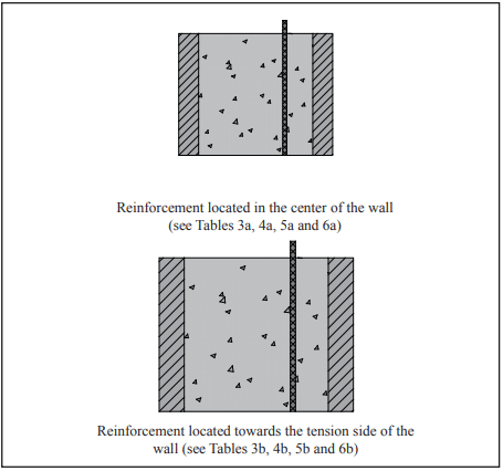
Two sets of tables are presented for each wall thickness. Tables 3a, 4a, 5a and 6a list resisting moment and resisting shear values for walls with the reinforcing steel located in the center of the wall. Centered reinforcing bars are effective for providing tensile resistance for walls which may be loaded from either side, such as an above grade exterior wall which is likely to experience both wind pressure and suction.
Tables 3b, 4b, 5b and 6b list resisting moment and resisting shear values for walls with the reinforcing steel offset from the center.
Placing the reinforcement farther from the compression face of the masonry provides a larger effective depth of reinforcement, d, and correspondingly larger capacities. A single layer of off-center reinforcement can be used in situations where the wall is loaded from one side only, such as a basement wall with the reinforcement located towards the interior. For walls where loads can be in both directions (i.e. pressure or suction), two layers of reinforcement are used: one towards the wall exterior and one towards the interior to provide increased capacity under both loading conditions. In Tables 3b, 4b, 5b and 6b, the effective depth of reinforcement, d, is a practical value which takes into account construction tolerances and the reinforcing bar diameter.
Figure 1 illustrates the two steel location cases.
Figure 1—Reinforcing Steel Locations
Table 3—Allowable Stress Design Capacities for 8-in. (203-mm) WallsA
Figure 1—Reinforcing Steel Locations
Table 4—Allowable Stress Design Capacities for 10-in. (254-mm) WallsA
Table 5—Allowable Stress Design Capacities for 12-in. (305-mm) WallsA
Table 6—Allowable Stress Design Capacities for 16-in. (406-mm) WallsA
DESIGN EXAMPLE
A warehouse wall will span 34 ft (10.4 m) between the floor slab and roof diaphragm. The walls will be constructed using 12 in. (305 mm) concrete masonry units. What is the required reinforcing steel size and spacing to support a wind load of 20 psf (0.96 kPa)?
From interpolation of Tables 1 and 2, respectively, the wall must be able to resist: M = 34,800 lb-in./ft (12.9 kN-m/m) V = 340 lb/ft (4.96 kN/m)
Assuming the use of offset reinforcement, from Table 5b, No. 6 bars at 40 in. on center (M#19 at 1,016 mm) or No. 7 bars at 48 in. (M#22 at 1,219 mm) on center provides sufficient strength: for No. 6 bars at 40 in. o.c. (M#19 at 1,016 mm): Mr = 35,686 lb-in./ft (13.3 kN-m/m) > M OK Vr = 2,299 lb/ft (33.5 kN/m) > V OK
for No. 7 bars at 48 in. (M#22 at 1,219 mm) : Mr = 40,192 lb-in./ft (14.9 kN-m/m) > M OK Vr = 2,133 lb/ft (31.1 kN/m) > V OK
As discussed above, since wind loads can act in either direction, two bars must be provided in each cell when using off-center reinforcement—one close to each faceshell.
Alternatively, No. 6 bars at 24 in (M#19 at 610 mm) or No. 8 at 40 in (M#25 at 1,016 mm) could have been used in the center of the wall.
NOTATION
As = area of nonprestressed longitudinal reinforcement, in.² (mm²) b = effective compressive width per bar, in. (mm) d = distance from extreme compression fiber to centroid of tension reinforcement, in. (mm) Em = modulus of elasticity of masonry in compression, psi (MPa) Es = modulus of elasticity of steel, psi (MPa) Fb = allowable compressive stress available to resist flexure only, psi (MPa) Fs = allowable tensile or compressive stress in reinforcement, psi (MPa) Fv = allowable shear stress, psi (MPa) f’m = specified compressive strength of masonry, psi (MPa) M = maximum calculated bending moment at section under consideration, in.-lb, (N-mm) Mr = flexural strength (resisting moment), in.-lb (N-mm) V = shear force, lb (N) Vr = shear capacity (resisting shear) of masonry, lb (N)
REFERENCES
International Building Code. International Code Council.
2012 Edition
2009 Edition
2006 Edition
Building Code Requirements for Masonry Structures. Reported by the Masonry Standards Joint Committee.
2011 Edition: TMS 402-11/ACI 530-11/ASCE 5-11
2008 Edition: TMS 402-08 /ACI 530-08/ASCE 5-08
2005 Edition: ACI 530-05/ASCE 5-05/TMS 402-05
Allowable Stress Design Tables for Reinforced Concrete Masonry Walls, TEK 14-19B. Concrete Masonry & Hardscapes Association, 2009.
Allowable Stress Design of Concrete Masonry Based on the 2012 IBC & 2011 MSJC, TEK 14-07C. Concrete Masonry & Hardscapes Association, 2011.
Sound barrier walls are increasingly being used to reduce the impact of traffic noise on properties abutting major urban traffic routes. Because concrete masonry possesses many desirable features and properties—excellent sound resistance, low cost, design flexibility, structural capability and durability, it is an excellent material for the design and construction of highway sound barrier walls.
Aesthetics is also an important consideration. Noise barriers significantly impact a highway’s visual impression. Visual qualities of noise barriers include overall shape, end conditions, color, texture, plantings and artistic treatment.
The variety of concrete masonry surface textures, colors and patterns has led to its extensive use in sound barrier walls.
Various types of concrete masonry walls may be used for sound barriers. Pier and panel walls are relatively easy to build and are economical due to the reduced thickness of the walls and the intermittent pier foundations. In addition, the piers can be offset with respect to the panels to achieve desired aesthetic effects. Pier and panel walls are also easily adapted to varying terrain conditions and are often used in areas that have expansive soils.
This TEK presents information on the structural design of concrete masonry pier and panel sound barrier walls. Requirements and considerations for reduction of highway traffic noise are discussed in TEK 13-03A, Concrete Masonry Highway Noise Barriers (ref. 2).
DESIGN
Building Code Requirements for Masonry Structures, ACI 530/ASCE 5/TMS 402 (ref. 1) includes requirements for allowable stress design, strength design and prestressed approaches. The allowable stress design approach was used to develop the designs in this TEK. Allowable stresses were increased by one-third, as permitted for load combinations which include wind or seismic loads. Allowable Stress Design of Concrete Masonry, TEK 14-07C (ref. 4), describes the basic design approach.
Materials and Workmanship
Since concrete masonry sound barrier walls are subject to a wide range of load conditions, temperatures and moisture conditions, the selection of proper materials and proper workmanship is very important to ensure durability and satisfactory structural performance. Accordingly, it is recommended that materials (concrete masonry units, mortar, grout and reinforcement) comply with applicable requirements contained in Building Code Requirements for Masonry Structures (ref. 1).
Lateral Loads
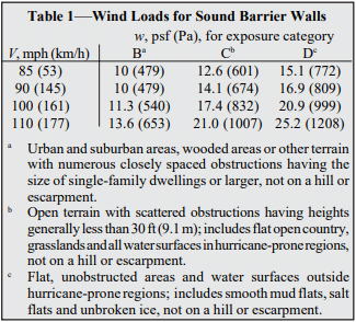
Design lateral loads should be in accordance with those specified by local or state building and highway departments. If design lateral loads are not specified, it is recommended that they conform to those specified in Minimum Design Loads for Buildings and Other Structures, ASCE 7 (ref. 3). Wind and earthquake loads required in this standard are briefly described in the following paragraphs.
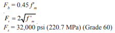
Design wind loads (F) on sound barrier walls may be determined as follows:
For the wall designs in this TEK, G is taken as 0.85 and C as 1.2. The minimum wind load specified in ASCE 7 is f 10 psf (479 Pa). For basic wind speeds of 85 mph (minimum), 90 mph, 100 mph, and 110 mph (53, 145, 161, and 177 kmph), the corresponding wind loads are listed in Table 1.
Earthquake loads (F ) on sound barrier walls may be p determined as follows, considering the wall system as a reinforced masonry non-building structure (ref. 3):
Seismic loads for a range of conditions are listed in Table 3.
Table 1—Wind Loads for Sound Barrier Walls
Table 2— Design Assumptions for Tables 4, 5, and 6
Table 2—Seismic Loads for Sound Barrier Walls
Deflections
Deflection considerations typically govern wall design for long spans and taller walls with greater lateral loads. Deflections are imposed to limit the development of vertical flexure cracks within the wall panel and horizontal flexure cracks near the base of the pier. The design information presented in this TEK is based on a maximum allowable deflection of L/240, where L is the wall span between piers.
DESIGN TABLES
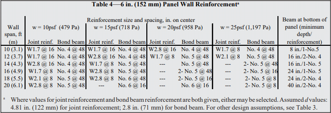
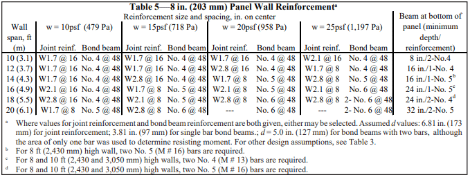
Design information for pier and panel walls is presented in Tables 4 through 7. Tables 4 and 5 provide horizontal reinforcing steel requirements for 6 in. and 8 in. (152 and 203 mm) panels, respectively. Horizontal reinforcement requirements can be met using either joint reinforcement or bond beams with reinforcing bars.
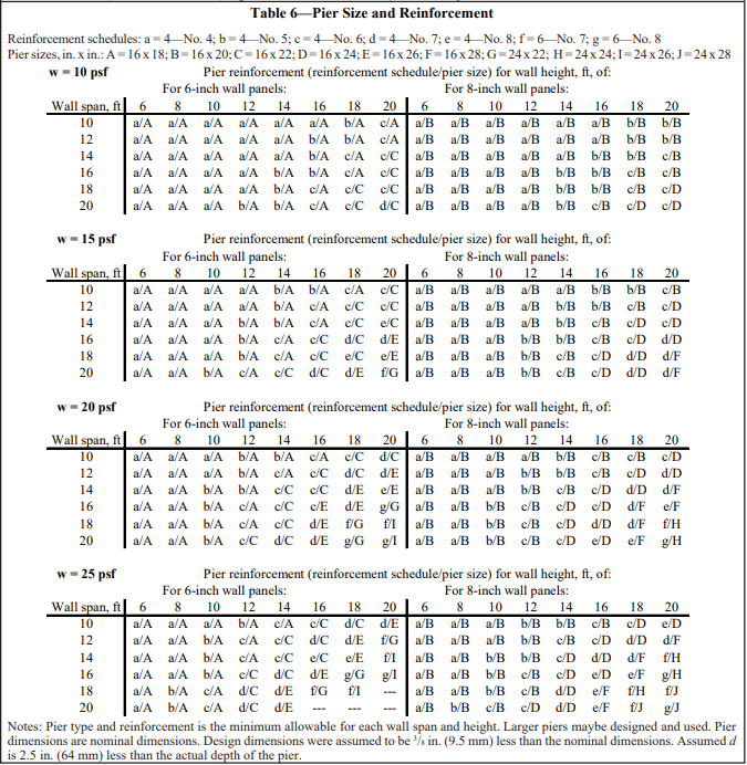
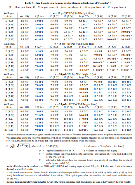
Table 6 provides pier size and reinforcement requirements for various lateral loads. Table 7 lists minimum sizes for pier foundations, as well as minimum embedment depths. These components of pier and panel walls are illustrated in Figure 1.
When pier and panels are used, walls are considered as deep beams, spanning horizontally between piers. Walls support their own weight, vertically, and also must resist lateral out-of-plane wind or seismic loads. The panels are built to be independent of the piers to accommodate masonry unit shrinkage and soil movement. For this design condition, wall reinforcement is located either in the horizontal bed joints or in bond beams. Wall reinforcement is based on maximum moments (M) and shears (V) in the wall panels, determined as follows:
The wall panels themselves are analyzed as simply supported beams, spanning from pier to pier.
In addition to the horizontal reinforcement, which transfers lateral loads to the piers, vertical reinforcement in the panels is required in Seismic Design Categories (SDC) C, D, E and F. Building Code Requirements for Masonry Structures (ref. 1) includes minimum prescriptive reinforcement as follows. In SDC C, vertical No. 4 (M #13) bars are located within 8 in. (203 mm) of the wall ends, and at 10 ft (3.0 m) on center along the length of the wall; minimum horizontal reinforcement requirements are satisfied by the primary reinforcement listed in Tables 4 and 5. In SDC D, E and F, vertical No. 4 (M #13) bars are located within 8 in. (203 mm) of the wall ends, and at 4 ft (1.22 m) on center along the length of the wall.
Table 6 shows pier size and vertical reinforcement requirements. Piers are designed as vertical cantilevers, not bonded with the walls, and pier reinforcement is based on maximum moment and shear, determined as follows:
Design assumptions for the pier and panel walls are given in Table 2. Note that allowable stresses were increased by one-third, as permitted for load combinations which include wind or seismic loads (ref. 1).
Requirements for concrete foundations supporting the concrete masonry piers are given in Table 7. These foundations can be constructed economically by drilling. The concrete foundation piers should contain vertical reinforcement (same as shown in Table 6) which should be properly lapped with vertical reinforcement in the concrete masonry piers. The embedment depths given in Table 7 are based on an allowable lateral passive soil pressure of 300 psf (14.4 kPa).
Table 4—6 in. (152 mm) Panel Wall Reinforcement
Table 5—8 in. (203 mm) Panel Wall Reinforcement
Table 6—Pier Size and Reinforcement
Table 7—Pier Foundation Requirements, Minimum Embedment/Diameter
DESIGN EXAMPLE
A pier and panel highway sound barrier is to be designed using the following parameters:
6 in. (152 mm) panel thickness
10 ft (3.05 m) wall height
14 ft (4.27 m) wall span
open terrain, stiff soil
basic wind speed is 90 mph (145 km/h)
SS = 0.25, SDC B
From Table 1, the design wind load is 14.1 psf (674 Pa) for a basic wind speed of 90 mph (145 km/h) and exposure C. Using Table 3, the design seismic load is determined to be 2.8 psf (0.13 kPa) for a 6 in. (152 mm) wall grouted at 48 in. (1219 mm), or less, on center, for SS = 0.25. Since the wind load is s greater, the wall will be designed for 14.1 psf (674 Pa).
Using Table 4, minimum horizontal panel reinforcement is either W1.7 (MW 11) joint reinforcement at 8 in. (203 mm) on center, or bond beams at 48 in. (1220 mm) on center reinforced with one No. 5 (M #16) bar. At the bottom, the panel requires a beam 16 in. (406 mm), or two courses, deep reinforced with one No. 5 (M # 16) bar (last column of Table 4). Because the wall is located in SDC B, vertical reinforcement is not required to meet prescriptive seismic requirements.
The minimum pier size is 16 x 18 in. (406 x 460 mm), reinforced with four No. 4 (M #13) bars, per Table 6. The pier foundation diameter is 18 in. (457 mm), and should be embedded at least 7.5 ft (2.29 m), per Table 7.
NOTATIONS
Af = area normal to wind direction, ft² (m²) Cf = force coefficient (see ref. 3) d = distance from extreme compression fiber to centroid of tension reinforcement, in. (mm) Em = modulus of elasticity of masonry in compression, psi (MPa) Es = modulus of elasticity of steel, psi (MPa) F = design wind load, psf (Pa) (see ref. 3) Fa = acceleration-based site factor (at 0.3 second period) (see ref. 3) Fm = allowable masonry flexural compression stress, psi (Pa) Fp = seismic force, psf (Pa) (see ref. 3) Fs = allowable tensile or compressive stress in reinforcement, psi (MPa) Fv = allowable shear stress in masonry, psi (MPa) f’m = specified compressive strength of masonry, psi (MPa) G = gust effect factor (see ref. 3) H = wall height, ft (m) I = importance factor (see ref. 3) Ip = component importance factor (assume equal to 1.0 for sound barrier walls) (see ref. 3) Kd = wind directionality factor (see ref. 3) Kz = velocity pressure exposure coefficient (see ref. 3) Kzt = hill and escarpment factor (see ref. 3) L = wall span, ft (m) M = maximum moment at the section under consideration, in.-lb (N-mm) n = ratio of elastic moduli, Es/Em P = applied lateral force, lb (N) qz = velocity pressure, psf (Pa) (see ref. 3) = 0.00256K KzKztKdv²I R = response modification coefficient (see ref. 3) Rp = component response modification factor (equal to 3.0 for reinforced masonry non-building structures) (see ref. 3) SDS = design short period spectral acceleration =⅔(FaSS), where SS varies from less than 0.25 to greater than 1.25, and Fa is dependent on SS and soil conditions at the site (see ref. 3) Ss = mapped maximum considered earthquake spectral response acceleration at short periods (see ref. 3) V = shear force, lb (N) v = basic wind speed, mph (km/h) (see ref. 3) Wp = weight of wall, psf (Pa) w = wind or seismic load, psf (Pa)
REFERENCES
Building Code Requirements for Masonry Structures, ACI 530-02/ASCE 5-02/TMS 402-02. Reported by the Masonry Standards Joint Committee, 2002.
Traditionally, empirical requirements have been used for the selection of masonry wall dimensions and lateral support spacing for resistance to wind pressures. These empirical requirements provide satisfactory results for buildings less than 35 ft (11 m) in height where the basic wind pressure does not exceed 25 psf (1197 Pa). This TEK addresses those cases where it is necessary or desirable to undertake a more thorough structural analysis of the lateral wind resistance of a concrete masonry wall or wall-pilaster combination.
Such analysis involves a knowledge of the magnitude and distribution of the wind force to various elements of a masonry structure and the flexural and shear strength of these elements. The information in this TEK provides guidelines for the design of masonry walls supported in both the vertical and horizontal directions.
WALLS
The need to investigate the lateral wind resistance capacity of a wall is usually greater in the case of plain (unreinforced) nonbearing or lightly loaded masonry walls because the vertical load on the wall may be insufficient to completely offset the development of flexural tension. Analysis of masonry walls is often based on the assumption that lateral loads are transmitted in the vertical direction with no end fixity at the lateral supports. Although this approach is straightforward, it may be overly conservative when the ratio of horizontal to vertical distances between lateral supports is relatively small and end fixity is developed. In such cases, end fixity and two-way bending can be utilized.
When wind loads are applied normal to a masonry wall surface, the loads are transmitted to horizontal supports (floors, roofs, beams) and/or vertical supports (cross walls, pilasters). Wall panels are usually assumed to function structurally as thin plates or slabs. For simplicity, walls are often designed to span horizontally between vertical supports or to span vertically between horizontal supports. However, walls can be designed assuming two-way bending using pilasters or cross walls as well as the roof structure and footing as supports. Assuming that the flexural resistance and rigidity of the walls in both the vertical and horizontal spans are known, the lateral load capacity and the proportion of the lateral load transmitted vertically and horizontally to the edge supports will depend on the restraint developed at the edges, the horizontal to vertical span ratio of the panel, and the distribution of the loads applied to the wall panels.
The curves in Figure 1 can be used to approximate the proportion of wind load transmitted in the vertical and horizontal directions. These curves are based on the assumption that the moment of inertia and modulii of elasticity of the walls will be the same in both the horizontal and vertical directions. The curves were derived by equating the theoretical formulas for calculating the maximum deflection for a strip of wall in both directions. It was further assumed that the walls either have no openings, or that any wall openings are located so that their effect on the stiffness of the wall panel is the same in both directions, and that the wall panels on each side of the support are similar in length and height.
When calculating the wind load to be carried by a vertical support, such as a pilaster, a value for K corresponding to the assumed support conditions at the edges of the wall panels and the appropriate wall panel length-to-height ratio is selected from the curves. Then, the value of wp is determined from the formula given at the top of Figure 1. This value, wp, represents the load which, when applied as a uniformly distributed load over the height of the pilaster, will approximate the actual wind load transmitted to the pilaster by the walls under the design conditions.
Figure 1—Approximate Horizontal and Vertical Wind Load Distribution
Design Example
To illustrate the use of the curves and formula given in Figure 1, assume a building with exterior walls spanning 12 ft (3.7 m) vertically between the floor and the roof is designed to resist a wind pressure of 20 psf (958 Pa). The walls are also supported horizontally at 18 ft (5.5 m) by pilasters which are built integrally with the wall. The roof loads will be carried by trusses simply supported on the pilasters, so the walls will be considered free at the top and fixed at the bottom and at the pilasters.
Selecting the appropriate value for K from the curve given for Case 1-A and a wall length-to-height ratio of 18/12 or 1.50, the wind load per foot of height to be carried by the pilasters, wp, may be calculated as follows:
The value of 328 lb/ft (4787 N/m) represents the uniformly distributed load which, when considered to be applied over the full height of the pilaster, will approximate the actual load transmitted to the pilasters by the adjacent walls under the design conditions. The moment and shear developed in the pilasters as a result of this load will depend on the assumed top and bottom support conditions for the pilaster.
The wall construction consists of 12 in. (305 mm) hollow concrete masonry units laid in running bond with face shell mortar bedding, using Type N portland cement lime mortar. Additional design information includes:
Section modulus, S = 159.9 in.³/ft (0.009 m³/m) Net area, An= 36 in.²/ft (0.08 m²/m) Allowable tensile stress parallel to bed joints = 1.33 x 38 psi = 50.5 psi (0.35 MPa) (ref. 1) Allowable tensile stress normal to bed joints = 1.33 x 19 psi = 25.3 psi (0.17 MPa) (ref. 1)
As already determined, the horizontal span carries 91% of the wind load. With the wall fixed at the ends, the maximum moment, M, in the horizontal span (from Figure 2) is:
The flexural tensile stress in the horizontal span, ft, is:
The allowable tensile stress for hollow units, Type N mortar, tension parallel to bed joints, was determined to be 50.5 psi (0.35 MPa). Since the calculated tensile stress is less than the allowable, the design meets the code criteria.
In the vertical span, the wall described above carries 9% (1 – 0.91) of the wind load. Since the wall is free at the top and fixed at the base, the maximum moment is:
The flexural tensile stress in the vertical span is:
This value can be reduced by the dead load stress on the wall at the point of maximum moment. Assuming that the wall weighs 50 lb/ft² (2394 N/m²):
This results in a net axial compressive stress of 7 psi (48.3 Pa).
PILASTERS
A pilaster is a thickened wall section or vertical support built contiguous with and forming a part of the masonry wall. Pilasters are often used to stiffen masonry walls and to provide all or part of the lateral support. They may be built of hollow or solid units (manufactured in one or two pieces), grouted hollow units or reinforced hollow units. Pilasters function primarily as flexural members when used only for lateral support although they can also be used to support vertical compressive loads.
When designing pilasters, the lateral loads transmitted to the pilasters by the adjacent wall panels must be determined. Figure 1 can be used to approximate the proportion of wind load which is transmitted horizontally to pilasters and to calculate the approximate wind load carried by a pilaster.
The formulas given in Figure 2 can be used to calculate the maximum moment and shear on a pilaster after wp and the support conditions for the pilaster have been determined.
Consider the design described in the previous design example. From Figure 1, it was determined that for Case 1-A with span ratio of 1.5, approximately 91% of the wind load is transmitted in the horizontal span. If the pilasters in the above example are assumed to be fixed at the bottom and simply supported at the top, the maximum moment and shear values are as follows:
The pilaster, therefore, should be designed to provide an allowable moment and shear resistance equal to or greater than the above values.
Figure 2—Formulas For Maximum Moment and Shear on Walls and Pilasters Subjected To Uniform Lateral Loads
NOTATION:
An = net cross-sectional area of masonry, in.²/ft (m²/m) ft = flexural tension in masonry, psi (MPa) H = height of wall, ft (m) K = proportion of wind load transmitted horizontally to pilasters or cross walls M = moment, in.-lb/ft (N•m/m) S = section modulus, in.³/ft (m³/m) Vmax = maximum shear, lb/ft (N/m) w = uniformly distributed wind load, psf (Pa) wd = design wind load on wall, psf (Pa) wp = uniform lateral load which approximates the actual wind load transmitted by the walls to the pilasters or cross walls, lb/ft of height (N/m) X = horizontal span of wall, from center to center of pilasters or cross walls, ft (m)
REFERENCES
Building Code Requirements for Masonry Structures, ACI 530-92/ASCE 5-92/TMS 402-92. Reported by the Masonry Standards Joint Committee, 1992.