Articulating Concrete Block for Erosion Control
INTRODUCTION
An articulating concrete block (ACB) system is a matrix of individual concrete blocks placed together to form an erosion-resistant overlay with specific hydraulic performance characteristics. The system includes a filter layer underlay that allows infiltration and exfiltration to occur while providing particle retention of the soil subgrade. The filter layer may be comprised of a geotextile or properly graded aggregate or both. The blocks within the matrix must be dense and durable while providing a matrix that is flexible and porous.
Articulating concrete block systems are used to provide protection to underlying soil materials. The term “articulating” implies the ability of individual blocks of the system to conform to changes in subgrade while remaining interlocked or otherwise restrained by virtue of the block geometric interlock and/or additional system components such as cables, ropes, geotextiles, or geogrids. The interlocking property provided by the special shapes of ACBs also allows for expansion and contraction. Long-term durability and sustainability relies on an appropriate engineered design based on site-specific hydrological and geotechnical conditions. They are either hand-placed or installed as pre-assembled mats on top of a filter layer on prepared subgrade, and act as a soil revetment.
Articulating concrete blocks (ACBs) are an effective erosion control system used to solve a wide variety of erosion problems:
- drainage channels
- wildlife habitat
- river fronts
- bridge abutments/piers
- coastal shorelines
- dikes and levees
- pipeline protection
- spillways
- boat ramps
- retention basins
- lake shorelines
- overflow channels
- low water crossings
- dam overtopping
The systems are easy to install, simple to produce, and environmentally friendly. ACB systems are often used as an alternative to cast-in-place concrete bulkheads and slope paving, gabions, soil cement, roller compacted concrete, or rock riprap. ACBs can also be used as grid pavers. However, grid pavers manufactured according to ASTM C1319, Standard Specification for Concrete Grid Paving Units (ref. 7), are not considered ACBs.
Articulating concrete blocks are produced in accordance with ASTM D6684, Standard Specification for Materials and Manufacture of Articulating Concrete Block (ACB) Revetment Systems (ref. 3). They can be made in a variety of shapes and thicknesses, and may even be colored according to preference. ACBs have excellent resistance to hydraulic shear and overtopping conditions. Design resources for ACBs include the Design Manual for Articulating Concrete Block and ACB Design Spreadsheet (refs. 2, 8).
ENVIRONMENTAL BENEFITS
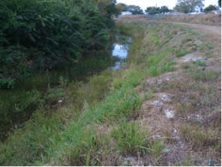
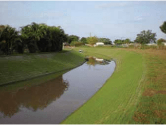
One of the environmental benefits of ACB erosion systems is that vertical cores and spaces can be incorporated throughout the system, which allows vegetation growth. Properly selected plant species can almost completely cover the entire hard surface of the ACBs, allowing them to blend in with the natural look of the project as well as water purification by absorbing nutrients and breaking down other pollutants. During peak storm events, the ACB layer beneath the vegetation will protect the soil from erosion. The ability to support the ecosystem’s habitat is a major advantage of ACB systems over other erosion control methods. Additional advantages of ACB systems are:
- serviceability
- aesthetics
- pedestrian safety
- sustainability
- cost effectiveness
- flexibility
The permeability of ACBs allows their use to preserve natural drainage and treatment systems. ACBs installed on filter media are pervious surfaces that reduce water runoff and flooding risks, improve water quality, reduce pollutants, recharge aquifers and prevent erosion. These environmental characteristics permit the use of ACBs on sustainable developments to preserve or improve existing sites and can be applicable to credits in some green building rating systems, such as LEEDTM, which is discussed in more detail below.
ACBs installed over drainage layers can also be used in a Best Management Practices (BMP) plan to preserve or improve existing sites, or in new developments. The system installed over a drainage layer preserves the natural drainage and treatment systems of the soil, reducing water runoff and flooding risks, improving water quality, reducing pollutants, recharging aquifers, and preventing erosion. Research on permeable pavers that are installed in a similar manner to ACBs (block over a gravel drainage layer) has also shown a promotion of aerobic biodegradation of hydrocarbons and reduction of nutrients (refs. 11, 12). When vegetated, they can also generate habitat. These qualities make ACBs a great solution for use in sustainable projects where water quantity and quality control are extremely important.
LEED Certification
ACBs can also make a significant contribution to project certification under Leader in Energy and Environmental Design (LEED) registered projects. Under LEED v3 for New Construction (ref. 9), ACB products can help attain points toward certification in the following categories: Sustainable Sites, Materials & Resources, and potentially Innovation in Design and Regional Priority Credits. These are briefly discussed below, based on LEED v3 for New Construction. Other versions of LEED may have different credit numbers, or slightly different criteria. For more detailed information on ACB’s potential contributions towards LEED credits, see TEK 06-09C, Concrete Masonry and Hardscape Products in LEED 2009 (ref. 10).
Sustainable Sites: ACBs can help capture up to 5 credits of the 26 possible in the following areas:
- Prerequisite—The project is required to reduce the pollution generated during construction. ACBs can contribute to preventing erosion, reducing dust when working as drivable surfaces, and constructing sediment basins with the added support for vegetation growth that increases water quality.
- Credit 5.1, Protect or Restore Habitat—ACBs can be used to restore erosion-prone areas by retaining soil and promoting plant growth.
- Credit 5.2, Maximize Open Spaces—Ponds constructed with ACBs may count as open space as long as they are vegetated and meet the maximum 1:4 (vertical : horizontal) side slope limit.
- Credit 6.1, Storm Design: Quantity Control—Using ACBs can reduce a site’s impermeable hardscaping for slope stability and erosion control, allowing stormwater to percolate into the ground and reducing runoff. In addition, receiving channels protected with ACBs can reduce erosion, reduce impervious surfaces and, when planted, contribute to the overall aesthetics and ecology.
- Credit 6.2, Storm Design: Quality Control—ACBs can also be used to reduce the amount of stormwater that requires treatment. As discussed above under Environmental Benefits, ACBs on gravel filters have been shown to improve runoff quality.
- Credit 7.1, Heat Island Effect: Non Roof—Open grid ACBs (at least 50% pervious) or with a Solar Reflectance Index (SRI) of at least 29 can be used in lieu of traditional concrete or asphalt to reduce the urban heat island effect.
Materials and Resources: ACBs can contribute towards 8 of the 14 possible credits in the following areas:
- Credit 2, Construction Waste Management— Damaged concrete products can be redirected to the manufacturing process for recycling and unused products can be reused on another project.
- Credit 3, Material Reuse—ACBs can potentially be salvaged from one project and reused in another.
- Credit 4, Recycled Content—Concrete products, including ACBs, can be manufactured using recycled materials that have been diverted from the waste stream.
- Credit 5, Regional Materials—Concrete hardscape products are usually available close to the point-of-use and are manufactured with local materials.
Innovation in Design: Projects can earn Innovation in Design credits by exceeding the LEED credit requirements, or by addressing innovative environmental strategies not specifically addressed in LEED, such as the life cycle environmental impact of the materials used.
Regional Priority Credits: Up to 4 LEED credits can be earned through Regional Priority Credits, which are designed to encourage designers to focus on specific regional needs. The credits are classified by zip code and designers have the option to excel in aspects of the project that are priorities in their region. ACBs could contribute to attain higher percentages on all the credits mentioned above to qualify for extra points.
ACB UNITS
ACB units complying with ASTM D6684, Standard Specification for Materials and Manufacture of Articulating Concrete Block (ACB) Revetment Systems (ref. 3), are produced as dry-cast (in a block machine) or wet-cast (with concrete and molds). Sampling and testing of dry-cast ACB units are performed in accordance with ASTM C140, Standard Test Method for Sampling and Testing Concrete Masonry Units and Related Units (ref. 6), for conformance with the requirements in Table 1. Sampling and testing of wet-cast units is performed in accordance with ASTM C39, Standard Test Method for Compressive Strength of Cylindrical Concrete Specimens and ASTM C42, Standard Test Method for Obtaining and Testing Drilled Cores and Sawed Beams of Concrete (refs. 4, 5).
Several varieties of ACB systems are available: interlocking, cable-tied and non-cable-tied matrices, and open cell and closed cell varieties. Open cell units contain open voids within individual units that facilitate the placement of aggregate and/or vegetated soil. Closed cell units are solid concrete elements that are capable of allowing vegetation growth between adjacent units. Figure 1 shows a variety of ACB units in plan view.

NOTE – For units produced by the wet-cast method, tests shall be conducted in accordance with Test Methods ASTM C39 and C42. For units produced by a dry-cast method, tests shall be conducted in accordance with Test Method ASTM C140.
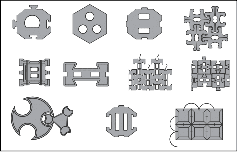
(Note that this is not all inclusive of available configurations. No endorsement or recommendation is intended.)
ACB INSTALLATION
Articulating concrete blocks can be installed by small construction crews with a modest amount of equipment. Installations are fast and are easy to inspect due to the visibility of all components.
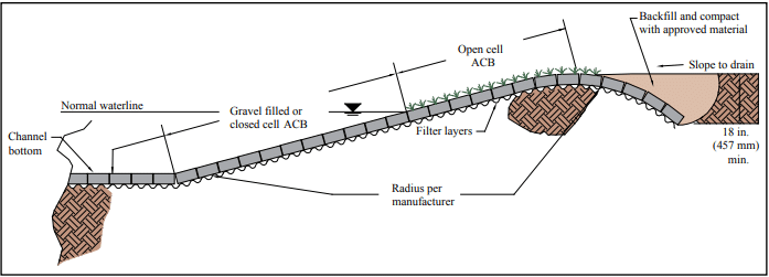
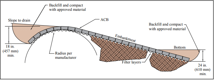
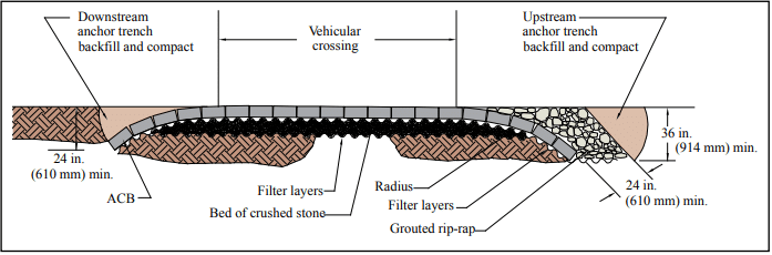
ACBs are installed on top of a filter layer over a prepared subgrade. The filter acts to protect and hold the subgrade in place while allowing bidirectional water penetration. Final subgrade elevation should be 0 to + ½ in. (12.7 mm) under a 10 ft. (3.05 m) straight edge. After the ACB installation is complete, the open cell voids or joints between the ACB units are filled with granular material or soil. Unit to unit vertical offset should be limited to the value utilized in the design. If vegetation is required, hydraulic seeding or mulching provides a low cost and highly effective method of establishing commonly used grasses and plants. In applications subject to continually flowing water, solid units should be used below the normal waterline or the voids of hollow units should be filled with gravel. Figures 2 through 4 show typical ACB cross-sections.
Installation methods depend on whether the ACB product being used is classified as cabled or as non-cabled.
Cabled Articulating Concrete Mats
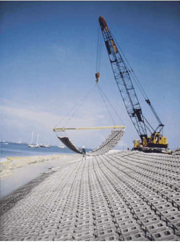
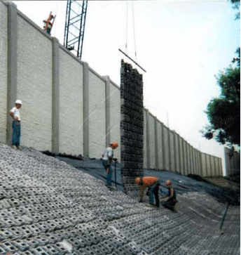
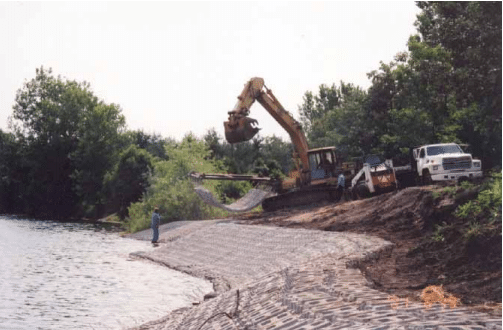
Cabled interlocking blocks have preformed horizontal holes cast in them so that high-strength cables or ropes (synthetic or steel) can be installed through the matrix of blocks binding them into a monolithic mattress. The cables or ropes are used to facilitate placement of the mat, normally by a spreader bar and crane, as shown in Figures 5 and 6. For design purposes, cables offer no hydraulic stability or structural value to the ACB mat or block system.
The blocks are pre-assembled into cabled mats in a controlled environment on or off the job site. The mats are lifted by the cables’ end loops, placed on the back of a flatbed truck, and shipped to the job site where they are again lifted and placed on the prepared slope. The mats can also be fabricated on site near the prescribed area, eliminating the need for additional trucking. Assembly of the blocks into mats makes it possible to install these systems underwater and on steep slopes.
Several commercially available cable systems can be manually placed on a shoreline or channel, and the cables then hand-inserted through the holes. An advantage of this process is that revetments with fewer seams can be constructed. Also, it is easier to hand-place the blocks around a radius or projection on a sloped bank, such as a culvert outlet. To accomplish this with pre-assembled ACB mats, custom-shaped mats must be fabricated or field piece work insertions are required. Both require careful planning, detailing, and execution in the field.
Non-Cabled Articulating Concrete Mats
Non-cabled blocks are cast in interlocking shapes to provide a positively connected matrix that is individually hand-placed by semi-skilled labor. The blocks are individually installed according to the geometry of the product. The typical block layout is oriented in the application’s centerline position. These blocks make it possible to install ACBs in areas that are restrictive to large construction equipment.
ACBs without cables can be suited to projects where complex site geometries and limited access are present. These non-cabled ACBs offer comparable shear resistance and some systems offer a higher percentage of open surface area when desired. These blocks are typically delivered in palletized cubes and are hand-placed at the job site. Since there are no cables involved, the material costs can be considerably less. ACBs without cables can be constructed in virtually seamless fields.
DESIGN CONSIDERATIONS
Existing and proposed project characteristics combined with the hydraulic design objectives will determine, through a factor of safety analysis, the ACB product that will best serve the project’s erosion control needs. A 1.5 factor of safety is common.
Guidelines for the selection and design of the appropriate ACB product are provided by the Design Manual for Articulating Concrete Block (ref. 2) and TEK 11-12A, Articulating Concrete Block Revetment Design—Factor of Safety Method (ref. 1).
The hydraulic forces which are considered in the design of erosion control projects using this technology are hydraulic lift, drag, and impact. ACBs have demonstrated the ability to resist high velocity flows in excess of 25 ft/s (7.6 m/s), usually associated with drainage channels, water control structures, dam spillways, and fast flowing rivers. While many of the forces created by water can be readily calculated, particularly uplift and drag, each project application has separate design considerations.
ACBs are not designed to add structural strength to the slopes. The protected slope must be geotechnically stable prior to placement of surface protection. Known as “flexible revetments,” ACB installations should not be placed on slopes which are steeper than the natural angle of repose of the soil. This is a different technology than retaining walls which resist lateral earth pressures.
Protruding height variances between adjacent blocks should be minimized and must be in accordance with the design value utilized. Grading beneath the block and fabric is critical to establishing an acceptable finished profile of the ACBs.
Filter layers are always placed under the ACBs. The function of the filter is critical, as it must retain the soil in place while letting water pass through without clogging. The filter layer must remain in intimate contact with the block and the soil to preclude soil particles from being transported down the slope beneath the geotextile. The key design points to consider in the filter selection are:
- Only woven monofilament or nonwoven needle-punched geotextiles should be considered for filter applications.
- The filter layer must have a long-term permeability capable of handling the required volume of water through a restricted surface area equal to the joint area of the articulating concrete block.
- The permeability of the filter layer must always be equal to or greater than the permeability of the protected soil unless a special bedding layer is provided.
- The filter layer needs only to retain the majority of particles beneath it, thus creating a filter bridge.
Care should be taken in the specification of the underlying geotextile filter layer. Appropriate ASTM test methods are available to characterize soil properties and should be done to develop the retention criteria and proper permeability. The geotextile must possess adequate strength and endurance properties to survive the process of installation and any long-term forces applied to it. ASTM D6684, Standard Specification for Materials and Manufacture of Articulating Concrete Block (ACB) Revetment Systems (ref. 3), provides strength requirements for geotextiles.
In most of these designs, the owner or architect should rely upon the engineering expertise of a qualified engineer to select the appropriate block type, filter layer, soil compaction, and design parameters. Proper material selection and construction practices are required and should be checked during installation.
REFERENCES
- Articulating Concrete Block Revetment Design—Factor of Safety Method, ACB-TEC-002-11, Concrete Masonry & Hardscapes Association, 2002
- Design Manual for Articulating Concrete Block, ACB- MAN-001-20, Concrete Masonry & Hardscapes Association, 2020.
- Standard Specification for Materials and Manufacture of Articulating Concrete Block (ACB) Revetment Systems, ASTM D6684. ASTM International, 2018.
- Standard Test Method for Compressive Strength of Cylindrical Concrete Specimens, ASTM C39/C39M. ASTM International, 2021.
- Standard Test Method for Obtaining and Testing Drilled Cores and Sawed Beams of Concrete, ASTM C42/42M. ASTM International, 2020.
- Standard Test Method for Sampling and Testing Concrete Masonry Units and Related Units, ASTM C140. ASTM International, 2023A.
- Standard Specification for Concrete Grid Paving Units, ASTM C1319. ASTM International, 2021.
- ACB Design Spreadsheet
- Leadership in Energy and Environmental Design (LEED) Green Building Rating System, v3. United States Green Building Council, 2009.
- Concrete Masonry and Hardscape Products in LEED 2009, TEK 06-09C, Concrete Masonry & Hardscapes Association, 2009.
- Hunt, W.F., Collins, K.A., Hathaway, J.M. Hydrologic and Water Quality Evaluation of Four Permeable Pavements in North Carolina, USA. Proceedings of the 9th International Conference on Concrete Block Paving. Buenos Aires, Argentina, 2009.
- Kirkpatrick, R., Campbell, R, Smyth, J., Murtagh, J., Knapton, J. Improvement Of Water Quality By Coarse Graded Aggregates In Permeable Pavements. Proceedings of the 9th International Conference on Concrete Block Paving. Buenos Aires, Argentina, 2009.