Resources

Design of Concrete Masonry Noncomposite (Cavity) Walls

INTRODUCTION

When selecting a building enclosure, concrete masonry cavity walls are considered to be one of the best solutions available for all types of buildings. From both an initial cost and life-cycle cost perspective, cavity wall construction is highly regarded as the prime choice in many applications.

Cavity walls typically consist of an inner wythe of concrete masonry units that are tied to an exterior wythe of architectural masonry units. The cavity space between the wythes is normally 2 to 4 ½ in. (51 to 114 mm) wide, easily accommodating rigid board insulation. The two wythes together provide a wall that is highly resistant to wind driven rain, absorbs and reflects sound, provides good thermal performance, and has excellent fire resistance characteristics.

Masonry walls constructed of two or more wythes can technically be classified in one of three ways, depending on how the wythes are designed and detailed. These wall types include composite, noncomposite and veneer assemblies. In noncomposite construction, covered in this TEK, each wythe is connected to the adjacent wythe with metal wall ties, but they are designed such that each wythe individually resists the loads imposed on it. Composite walls are designed so that the wythes act together as a single element to resist structural loads. This requires the masonry wythes to be connected by masonry headers or by a mortar- or grout-filled collar joint and wall ties (see ref. 4). In a veneer wall, the backup wythe is designed as the loadbearing system while the veneer provides a nonloadbearing architectural wall finish that transfers loads to the backup wythe through wall ties (see refs. 5, 6). Although Building Code Requirements for Masonry Structures (ref. 1) defines a cavity wall as a noncomposite masonry wall, the term cavity wall is also commonly used to describe a veneer wall with masonry backup.

This TEK illustrates the design of noncomposite concrete masonry walls based on Building Code Requirements for Masonry Structures (ref. 1), referred to here as the MSJC code. Each wythe of a noncomposite wall system can be designed to accommodate all types of loads, including gravity loads from roofs, walls and floors, as well as lateral loads from wind or earthquakes. The MSJC code design provisions are used to size these masonry walls.

STRUCTURAL DESIGN

The MSJC code includes noncomposite design provisions for both allowable stress design (Chapter 2) and empirical design (Chapter 5). The assumptions and relevant governing equations for each of these design approaches is given in references 2 and 3 respectively.

Concrete masonry cavity walls can be designed as either reinforced or unreinforced walls. For unreinforced design, flexural tensile stresses in masonry are resisted by bond developed between the masonry units and mortar; axial tension is not permitted (ref. 1). If direct axial tension is encountered in a design, reinforcement must be used. In reinforced masonry design, all tension is assumed to be resisted by reinforcement.

Empirical Design

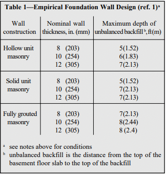
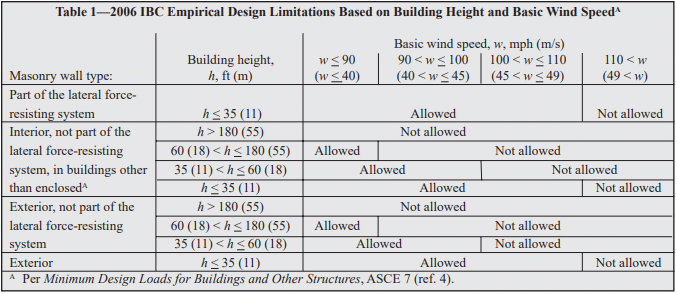
Empirical design can be an expedient approach for typical loadbearing structures subjected to nominal wind loads (basic wind speed ≤ 110 mph, (177 km/h) (MSJC 5.1.2.2) and located in areas of low seismic risk, as it cannot be used for the design of seismic force resisting systems in SDC (Seismic Design Category) B or higher (MSJC 5.1.2.1). Empirical design utilizes prescriptive provisions, outlining criteria such as wall height to thickness ratios, minimum wall thickness and maximum building height.

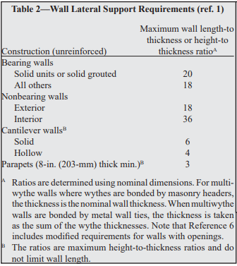
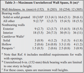
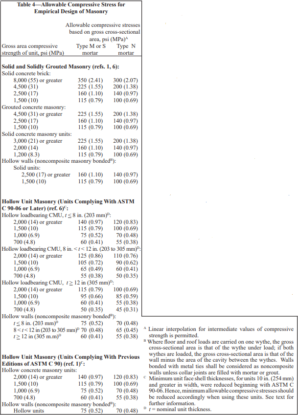
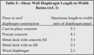
References 1 and 3 contain maximum length-to-thickness or height-to-thickness ratios for empirically designed walls. When using these ratios for noncomposite multiwythe walls, the total wall thickness is taken as the sum of the nominal thicknesses of each wythe, neglecting the presence of any cavity thickness. Compressive stress is based on the gross cross-sectional area of all wythes, including hollow cells but not including the cavity between the wythes. When floor or roof loads are carried on only one wythe, only the gross cross-sectional area of that wythe is used to check the axial capacity. In addition, these walls must meet the following requirements for wall ties connecting the wythes:

  • wall ties of wire size W2.8 (3/16 in., MW 18), or metal wire of equivalent stiffness, spaced at a maximum of 24 in. (610 mm) o.c. vertically and 36 in. (914 mm) o.c. horizontally, with at least one wall tie for each 4½ ft² (0.42 m²) of wall area,
  • walls constructed with hollow units must use rectangular ties,
  • walls constructed with solid units must use Z-shaped ties with hooks at least 2 in. (51 mm) long,
  • wall ties may not have drips,
  • additional ties are required within 12 in. (305 mm) of all openings and must be spaced no more than 3 ft (914 mm) apart around the perimeter of the opening.

Requirements for bonding with joint reinforcement are the same as those for wall ties with the following exceptions: cross wire size may not be smaller than W1.7 (9 gage, MW 11) and the supported wall area per cross wire may not exceed 2 ft² (0.25 m²). In addition, the longitudinal wires must be embedded in mortar.

Allowable Stress Design

Similar to empirical design, MSJC allowable stress design includes prescriptive requirements for bonding wythes of noncomposite walls via wall ties, adjustable ties and joint reinforcement.

For rectangular ties, Z ties (for use with other than hollow units) and ladder or tab-type joint reinforcement, ties or cross wires of joint reinforcement, ties must be placed with a maximum spacing of 36 in. (914 mm) horizontally and 24 in. (610 mm) vertically. The minimum number of ties is one per:

  • 2 ft² (0.25 m²) of wall for wire size W 1.7 (9 gage, MW 11), and
  • 4½ ft² (0.42 m²) of wall for wire size W 2.8 (3/16 in., MW 18).

For adjustable ties, one tie must be provided for each 1.77 ft² (0.16 m²) of wall; maximum horizontal and vertical spacing is 16 in. (406 mm); misalignment of bed joints from one wythe to the other may not exceed 1 ¼ in. (31.8 mm); the maximum clearance between connecting parts of the tie is 1/16 in. (1.6 mm); and pintle ties must have at least two pintle legs of wire size W2.8 (3/16 in., MW 18) (see also Figure 1).

For noncomposite masonry walls, the following additional requirements apply.

  • Collar joints are not to contain headers, or be filled with mortar or grout.
  • Gravity loads from supported horizontal members are to be resisted by the wythe nearest the center of the span.
  • Bending moments about the weak axis of the wall and transverse loads are distributed to each wythe according to relative stiffness. This can be determined by:
    Wi = WT [EmIi/(EmIi+ EmI0)]
    Wo = WT [EmI0/(EmIi+ EmI0)]
  • Loads acting parallel to the wall are resisted by the wythe to which they are applied.
  • The cavity width between the wythes is limited to 4½ in. (114 mm) unless a detailed wall tie analysis is performed.

DESIGN EXAMPLES

The following examples illustrate the use of noncomposite masonry employing empirical and allowable stress design methods. Although there are no specific provisions in MSJC for noncomposite wall design using strength design, strength design could be used provided the same load distribution principles as presented for allowable stress design are employed.

Empirical Design Design Example:
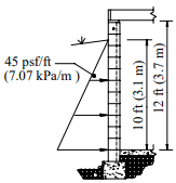
Design the top story of a two-story noncomposite double wythe masonry wall system supported on continuous footings. Note that the design of the lower story, though not shown, is performed in the same manner, except that the floor live and dead loads from the upper story are also accounted for.

Given:

unsupported wall height= 10 ft (3.01 m)
superimposed gravity dead load= 220 plf (3.2 kN/m)
superimposed gravity live load= 460 plf (6.7 kN/m)
net superimposed uplift from wind= 120 plf (1.8 kN/m)
wind pressure= 24 psf (1,149 Pa)
eccentricity of all gravity loads= 0
f’m= 1,500 psi (10.3 MPa)
Em= 1,350 ksi (9,308 MPa)


Wall lateral support requirement: l/t or h/t < 18, so minimum required wall thickness = h/18
= 10 ft (12 in./ft)/18
= 6.7 in. (169 mm)

Try a 4-in. (102 mm) outer wythe and 6-in. (152 mm) inner wythe (providing a total nominal wall thickness of 10 in. (254 mm)), and check allowable axial compressive stress due to dead and live loads (gravity loads are carried by the inner wythe only):

dead:roof220 lb/ft
 wythe = 10 ft x 26 psf (ref. 8)260 lb/ft
live:roof460 lb/ft
total load: 940 lb/ft (13.7 kN/m)


Gross area of 6-in. (152-mm) wythe = 67.5 in.²/ft (ref. 7)
fa = 940 lb/ft/(67.5 in.²/ft) = 13.9 psi (0.096 MPa)
Fa = 75 psi (0.52 MPa) for Type M or S mortar, 70 psi (0.48 MPa) for Type N mortar (ref. 1)
fa < Fa (OK for all mortar types)

Per MSJC code section 5.8.3.1, the net uplift on the roof must be resisted by an anchorage system. Use a bond beam at the top of the inner wythe with vertical reinforcement to the foundation to provide this resistance.

ASD Reinforced Design Example:
Given:

unsupported wall height= 18 ft (5.5 m)
wind load, w= 36 psf (1,724 Pa)
net roof uplift at top of wall= 400 plf (5.8 kN/m) )
eccentricity of all vertical loads= 0
f’m= 1,500 psi (0.0718 MPa )
unit density= 115 pcf (1,842 kg/m³)
Grade 60 reinforcement 

Note: The 36 psf (1,724 Pa) wind load is much higher than is generally applicable when using empirical design.

Design the inside wythe first, as it must resist the uplift in addition to the flexural loads. Try two 6-in. (152 mm) wythes with No. 5 (M #16) reinforcement at 32 in. (813 mm) o.c.

Determine reinforcement needed for uplift at midheight:
uplift = 400 lb/ft – 34 lb/ft² (18 ft/2) = 94 lb/ft (1.37 kN/m) (ref. 8)
reinforcement needed = [(94 lb/ft)(32 in.)/(12 in./ft)]/[1.333(24,000 psi)] = 0.0078 in.²
As available for flexure = 0.31 – 0.0078 = 0.3022 in.²
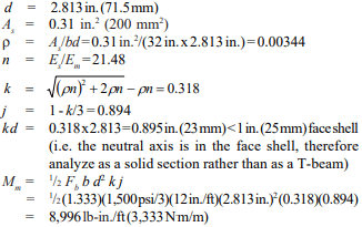
Ms = FsAsjd = 1.333 (24,000 psi) (0.3022 in.²)(0.894)(2.813 in.)
= 24,313 lb-in. for 32 in. width
= 9,117 lb-in./ft (3,378 N⋅m/m) > 8,996 lb-in./ft (3,333 N⋅m/m), therefore Mm controls

Determine applied moment:
Since the wythes are identical, each would carry ½ the lateral load or ½ (36 psf) = 18 psf (124 kPa)
Mmax = wl²/8 = (18 psf)(18 ft)²(12 in./ft)/8
= 8,748 lb-in./ft (3,241 N⋅m/m) < 8,996 lb-in./ft (3,333 N⋅m/m) OK

Check shear:
Vmax = wl/2 = (18psf)(18 ft)/2 = 162 lb/ft (2.36 kN/m)
fv = Vmax/bd = 162 lb/ft/(12 in.)(2.813 in.) = 4.80 psi (33 kPa)
Fv = 37 x 1.333 = 51 psi (351 kPa)
4.80 psi (33 kPa) < 51 psi (351 kPa) OK

A quick check of the outside wythe shows that the same reinforcement schedule will work for it as well. Therefore, use two 6-in. (152-mm) wythes with No. 5 (M #16) vertical reinforcement at 32 in. (813 mm) o.c.

This wall could be designed using an unreinforced 4-in. (102 mm) outside wythe and a reinforced 8-in. (203-mm) inside wythe, with lateral loads distributed to each wythe according to the uncracked stiffness per MSJC section 1.9.2. Experience has shown, however, that the design would be severely limited by the capacity of the unreinforced outside wythe. Additionally, such a design could be used only in SDC A or B since 4-in. (102 mm) concrete masonry does not have cores large enough to reinforce.

Another alternative would be to design this system treating the 4 in. (102 mm) outer wythe as a nonloadbearing veneer. Designing this wall as a 4-in. (102 mm) veneer with an 8-in. (203 mm) reinforced structural backup wythe would result in No. 5 bars at 16 in. (M #16 at 406 mm) on center. This is the same amount of reinforcement used in the example above (two 6-in. (152 mm) wythes with No. 5 (M #16) at 32 in. (813 mm) on center). However, because the 6-in. (152 mm) units have smaller cores, 30% less grout is required.

The design using two 6-in. (152-mm) reinforced wythes has the following advantages over veneer with structural backup:

  • no limitation on SDC as when a veneer or an unreinforced outer wythe is used,
  • no limitation on wind speed as with a veneer,
  • equal mass on both sides of the wall permitting the use of the prescriptive energy tables for integral insulation, and
  • the flexibility of using units with different architectural finishes on each side.

NOMENCLATURE

As          = effective cross-sectional area of reinforcement, in.²(mm²)
b            = width of section, in. (mm)
d            = distance from extreme compression fiber to centroid of tension reinforcement, in. (mm)
Em         = modulus of elasticity of masonry, psi (MPa)
Es          = modulus of elasticity of steel, psi (MPa)
Fa          = allowable compressive stress due to axial load only, psi (kPa)
Fb          = allowable compressive stress due to flexure only, psi (kPa)
Fs          = allowable tensile or compressive stress in reinforcement, psi (kPa)
Fv          = allowable shear stress in masonry, psi (MPa)
fa           = calculated compressive stress in masonry due to axial load only, psi (kPa)
f’m         = specified compressive strength of masonry, psi (kPa)
h            = effective height, in. (mm)
fv           = calculated shear stress in masonry, psi (MPa)
Ii            = average moment of inertia of inner wythe, in.4/ft (m4/m)
Io           = average moment of inertia of outer wythe, in.4/ft (m4/m)
j             = ratio of distance between centroid of flexural compressive forces and centroid of tensile forces to depth d
k           = ratio of distance between compression face of wall and neutral axis to depth d
l            = clear span between supports, in. (mm)
M          = moment at the section under consideration, in.-lb/ft (N⋅m/m)
Mm       = flexural capacity (resisting moment) when masonry controls, in.-lb/ft (N⋅m/m)
Mmax   = maximum moment at the section under consideration, in.-lb/ft (N⋅m/m)
Ms        = flexural capacity (resisting moment) when reinforcement controls, in.-lb/ft (N⋅m/m)
t            = nominal thickness of a member, in. (mm)
Vmax    = maximum shear at the section under consideration, lb/ft (kN/m)
Wi        = percentage of transverse load on inner wythe
Wo       = percentage of transverse load on outer wythe
WT       = total transverse load
w         = wind pressure, psf (Pa)
ρ          = reinforcement ratio

REFERENCES

  1. Building Code Requirements for Masonry Structures, ACI 530-02/ASCE 5-02/TMS 402-02. Reported by the Masonry Standards Joint Committee, 2002.
  2. ASD of Concrete Masonry (2012 IBC & 2011 MSJC), TEK 14-07C, Concrete Masonry & Hardscapes Association, 2004.
  3. Empirical Design of Concrete Masonry Walls, TEK 1408B, Concrete Masonry & Hardscapes Association, 2003
  4. Structural Design of Unreinforced Composite Masonry, TEK 16-02B, Concrete Masonry & Hardscapes Association, 2001.
  5. Concrete Masonry Veneers, TEK 03-06C, Concrete Masonry & Hardscapes Association, 2012.
  6. Reinforced Composite Concrete Masonry Walls, TEK 1603B, Concrete Masonry & Hardscapes Association, 2006.
  7. Weights and Section Properties of Concrete Masonry Assemblies, CMU-TEC-002-23, Concrete Masonry & Hardscapes Association, 2023.


Allowable Stress Design of Concrete Masonry Foundation Walls

INTRODUCTION

Basements provide: economical living, working and storage areas; convenient spaces for mechanical equipment; safe havens during tornadoes and other violent storms; and easy access to plumbing and ductwork. Concrete masonry is well suited to basement and foundation wall construction due to its inherent durability, compressive strength, economy, and resistance to fire, termites, and noise.

Traditionally, residential basement walls have been constructed of plain (unreinforced) concrete masonry, often designed empirically. Walls over 8 ft (2.4 m) high or with larger soil loads are typically designed using reinforced concrete masonry or using design tables included in building codes such as the International Building Code (ref. 4).

DESIGN LOADS

Soil imparts a lateral load on foundation walls. For design, the load is traditionally assumed to increase linearly with depth resulting in a triangular load distribution. This lateral soil load is expressed as an equivalent fluid pressure, with units of pounds per square foot per foot of depth (kPa/m). The maximum force on the wall depends on the total wall height, soil backfill height, wall support conditions, soil type, and the existence of any soil surcharges. For design, foundation walls are typically assumed to act as simple vertical beams laterally supported at the top and bottom.

Foundation walls also provide support for the structure above, transferring vertical loads to the footing. When foundations span vertically, this vertical compression counteracts flexural tension, increasing the wall’s resistance to flexure. In low-rise construction, these vertical loads are typically small in relation to the compressive strength of concrete masonry. Further, if the wall spans horizontally, vertical compression does not offset the flexural tension. Vertical load effects are not included in the tables and design example presented in this TEK (references 2 and 3 include vertical load effects).

EMPIRICAL DESIGN

The empirical design method uses historical experience to proportion and size masonry elements. Empirical design is often used to design concrete masonry foundation walls due to its simplicity and history of successful performance.

Table 1 lists the allowable backfill heights for 8, 10 and 12-inch (203, 254 and 305 mm) concrete masonry foundation walls. Table 1 may be used for foundation walls up to 8 feet (2.4 m) high under the following conditions (ref. 1):

  1. terrain surrounding the foundation wall is graded to drain surface water away from foundation walls,
  2. backfill is drained to remove ground water away from foundation walls,
  3. tops of foundation walls are laterally supported prior to backfilling,
  4. the length of foundation walls between perpendicular masonry walls or pilasters is a maximum of 3 times the foundation wall height,
  5. the backfill is granular and soil conditions in the area are non-expansive,
  6. masonry is laid in running bond using Type M or S mortar, and
  7. units meet the requirements of ASTM C 90 (ref. 6).

Where these conditions cannot be met, the wall must be engineered using either an allowable stress design (see following section) or strength design procedure (see ref. 5).

WALL DESIGN

Tables 2 through 4 of this TEK have been rationally designed in accordance with the allowable stress design provisions of Building Code Requirements for Masonry Structures (ref. 1) and therefore meet the requirements of the International Building Code even though the latter limits reinforcment spacing to 72 in. (1829 mm) when using their tables. Additional reinforcement alternatives may be appropriate and can be verified with an engineering analysis.

Tables 2, 3 and 4 list reinforcement options for 8, 10 and 12-in. (203, 254 and 305-mm) thick walls, respectively. The effective depths of reinforcement, d, (see Table notes) used are practical values, taking into account variations in face shell thickness, a range of bar sizes, minimum required grout cover, and construction tolerances for placing the reinforcing bars.

Tables 2 through 4 are based on the following:

  1. no surcharges on the soil adjacent to the wall and no hydrostatic pressure,
  2. negligible axial loads on the wall,
  3. wall is simply supported at top and bottom,
  4. wall is grouted only at reinforced cells,
  5. section properties are based on minimum face shell and web thicknesses in ASTM C 90 (ref. 6),
  6. specified compressive strength of masonry, f’m, is 1,500 psi (10.3 MPa),
  7. reinforcement yield strength, fy, is 60,000 psi (414 MPa),
  8. modulus of elasticity of masonry, Em, is 1,350,000 psi (9,308 MPa),
  9. modulus of elasticity of steel, Es, is 29,000,000 psi (200,000 MPa),
  10. maximum width of compression zone is six times the wall thickness (where reinforcement spacing exceeds this distance, the ability of the plain masonry outside the compression zone to distribute loads horizontally to the reinforced section was verified assuming two-way plate action),
  11. allowable tensile stress in reinforcement, Fs, is 24,000 psi (165 MPa),
  12. allowable compressive stress in masonry, Fb, is f’m (500 psi, 3.4 MPa),
  13. grout complies with ASTM C 476 (2,000 psi (14 MPa) if property spec is used) (ref. 7), and
  14. masonry is laid in running bond using Type M or S mortar and face shell mortar bedding.

DESIGN EXAMPLE

Wall: 12-inch (305 mm) thick, 12 feet (3.7 m) high.

Loads: equivalent fluid pressure of soil is 45 pcf (7.07 kPa/ m), 10 foot (3.1 m) backfill height. No axial, seismic, or other loads.

Using Table 4, #8 bars at 40 in. (M 25 at 1016 mm) o.c. are sufficient.

CONSTRUCTION ISSUES

This section is not a complete construction guide, but rather discusses those issues directly related to structural design assumptions. Figures 1 and 2 illustrate typical wall support conditions, drainage, and water protection.

Before backfilling, the floor diaphragm must be in place or the wall must be properly braced to resist the soil load. In addition to the absence of additional dead or live loads following construction, the assumption that there are no surcharges on the soil also means that heavy equipment should not be operated close to basement wall systems that are not designed to carry the additional load. In addition, the backfill materials should be placed and compacted in several lifts, taking care to prevent wall damage. Care should also be taken to prevent damaging the drainage, waterproofing, or exterior insulation systems, if present.

REFERENCES

  1. Building Code Requirements for Masonry Structures, ACI 530-99/ASCE 5-99/TMS 402-99. Reported by the Masonry Standards Joint Committee, 1999.
  2. International Building Code. International Code Council, 2000.
  3. Strength Design of Reinforced CM Foundation Walls, TEK 15-02B, Concrete Masonry & Hardscapes Association, 2004.
  4. Standard Specification for Loadbearing Concrete Masonry Units, ASTM C 90-01. American Society for Testing and Materials, 2001.
  5. Standard Specification for Grout Masonry, ASTM C476- 01. American Society for Testing and Materials, 2001.

Empirical Design of Concrete Masonry Walls

INTRODUCTION

Empirical design is a procedure of proportioning and sizing unreinforced masonry elements based on known historical performance for a given application. Empirical provisions preceded the development of engineered masonry design, and can be traced back several centuries. This approach to design is based on historical experience in lieu of analytical methods. It has proven to be an expedient design method for typical loadbearing structures subjected to relatively small wind loads and located in areas of low seismic risk. Empirical design has also been used extensively for the design of exterior curtain walls and interior partitions.

Using empirical design, vertical and lateral load resistance is governed by prescriptive criteria which include wall height to thickness ratios, shear wall length and spacing, minimum wall thickness, maximum building height, and other criteria, which have proven to be effective through years of experience.

This TEK is based on the provisions of Section 2109 of the International Building Code (IBC) (ref. 1). These empirical design requirements do not apply to other design methods such as allowable stress or limit states design. For empirical design of foundation walls, see TEK 15-01B, Allowable Stress Design of Concrete Masonry Foundation Walls (ref. 2)

APPLICABILITY OF EMPIRICAL DESIGN

The IBC allows elements of masonry structures to be designed by empirical methods when assigned to Seismic Design Category (SDC) A, B or C, subject to additional restrictions described below. When empirically designed elements are part of the seismic lateral force resisting system, however, their use is limited to SDC A.

Empirical design has primarily been used with masonry laid in running bond. When laid in stack bond, the IBC requires a minimum amount of horizontal reinforcement (0.003 times the wall’s vertical cross-sectional area and spaced not more than 48 in. (1,219 mm) apart).

In addition, buildings that rely on empirically designed masonry walls for lateral load resistance are allowed up to 35 ft (10.7 m) in height.

The 2003 IBC restricts empirical design to locations where the basic wind speed (three-second gust, not fastest mile) is less than or equal to 110 mph (79 m/s), as defined in Minimum Design Loads for Buildings and Other Structures, ASCE 7 (ref. 3). A wind speed of this velocity generally applies along the East and Gulf coasts of the United States.

The 2006 IBC further refines the empirical design limitations. Whereas with the 2003 IBC, the designer need only check the SDC and basic wind speed, with the 2006 IBC, to use empirical design the designer must check:

  • SDC,
  • basic wind speed,
  • building height, and
  • location of gravity loads resultant.

The limitations based on SDC are the same as in the 2003 IBC, described above. Building height and basic wind speed conditions where empirical design is permitted under the 2006 IBC are summarized in Table 1.

The 2006 IBC also requires the resultant of gravity loads to fall within the kern of the masonry element, to avoid imparting tension to the element. This area is defined as: within the center third of the wall thickness, or, for foundation piers, within the central area bounded by lines at one-third of each cross-sectional dimension of the pier.

DESIGN PROVISIONS

Minimum Wall Thickness

Empirically designed (unreinforced) bearing walls of one story buildings must be at least 6 in. (152 mm) thick. For buildings more than one story high, walls must be at least 8 in. (203 mm) thick. The minimum thickness for unreinforced masonry shear walls and for masonry foundation walls is also 8 in. (203 mm). Note that the 2003 IBC allows shear walls of one-story buildings to have a minimum thickness of 6 in. (152 mm).

Lateral Support

Lateral support for walls can be provided in the horizontal direction by cross walls, pilasters, buttresses and structural frame members, or in the vertical direction by floor diaphragms, roof diaphragms and structural frame members, as illustrated in Figure 1. For empirically designed walls, such support must be provided at the maximum intervals given in Tables 2 and 3. Note that the span limitations apply to only one direction; that is, the span in one direction may be unlimited as long as the span in the other direction meets the requirements of Tables 2 or 3.

Allowable Stresses

Allowable stresses in empirically designed masonry due to building code prescribed vertical (gravity) dead and live loads (excluding wind or seismic) are given in Table 4.

Table 4 includes two sets of compressive stresses for hollow concrete masonry units (CMU). The first set, titled “Hollow Unit Masonry (Units Complying With ASTM C 90- 06 or Later)” apply to most CMU currently available. The 2006 edition of the CMU specification, Standard Specification for Loadbearing Concrete Masonry Units, ASTM C 90 (ref. 7), included slightly reduced minimum face shell thickness requirements for CMU 10 in. (254 mm) and greater in width. These smaller face shells require a corresponding adjustment to the allowable compressive stresses. The values currently published in the 2006 IBC (“Hollow Unit Masonry (Units Complying With Previous Editions of ASTM C 90)” in Table 4), apply to the previous face shell thicknesses, and should only be used if the CMU to be used have the thicker face shells listed in previous editions of ASTM C 90. This distinction is not applicable to masonry that will be solidly grouted.

Calculated compressive stresses for both single and multiwythe walls are determined by dividing the design load by the gross cross-sectional area of the wall, excluding areas of openings, chases or recesses. The area is based on the specified dimensions of masonry, rather than on nominal dimensions. In multiwythe walls, the allowable stress is determined by the weakest combination of units and mortar shown in Table 4.

In addition, the commentary to Building Code Requirements for Masonry Structures (refs. 6, 8) contains additional guidance for concentrated loads. According to the commentary, when concentrated loads act on empirically designed masonry, the course immediately under the point of bearing should be a solid unit or be filled solid with mortar or grout. Further, when the concentrated load acts on the full wall thickness, the allowable stresses under the load may be increased by 25 percent. The allowable stresses may be increased by 50 percent when concentrated loads act on concentrically placed bearing plates that are greater than one-half but less than the full area.

Anchorage for Lateral Support

Where empirically designed masonry walls depend on cross walls, roof diaphragms, floor diaphragms or structural frames for lateral support, it is essential that the walls be properly anchored so that the imposed loads can be transmitted from the wall to the supporting element. Minimum anchorage requirements for intersecting walls and for floor and roof diaphragms are shown in Figures 2 and 3, respectively.

Masonry walls are required to be anchored to structural frames that provide lateral support by ½ in. (13 mm) diameter bolts spaced at a maximum of 4 ft (1.2 m), or with other bolts and spacings that provide equivalent anchorage. The bolts must be embedded a minimum of 4 in. (102 mm) into the masonry.

In addition, the 2006 IBC requires the designer to check the roof loading for net uplift and, where net uplift occurs, to design the anchorage system to entirely resist the uplift.

Shear Walls

Where the structure depends on masonry walls for lateral stability against wind or earthquake forces, shear walls must be provided parallel to the direction of the lateral forces as well as in a perpendicular plane, for stability.

Requirements for empirically designed masonry shear walls are shown in Figure 4.

Shear wall spacing is determined empirically by the length-to-width aspect ratio of the diaphragms that transfer lateral forces to the shear walls, as listed in Table 5. In addition, roofs must be designed and constructed in a manner such that they will not impose thrust perpendicular to the shear walls to which they are attached.

The height of empirically designed shear walls is not permitted to exceed 35 ft (10.7 m). The minimum nominal thickness of shear walls is 8 in. (203 mm), except under the 2003 IBC, which allows shear walls of one-story buildings to have a minimum thickness of 6 in. (152 mm).

Bonding of Multiwythe Walls

Wythes of multiwythe masonry walls are required to be bonded together. Bonding can be achieved using masonry headers, metal wall ties, or prefabricated joint reinforcement, as illustrated in Figure 5. Various empirical requirements for each of these bonding methods are given below.

Bonding of solid unit walls with masonry headers.
Where masonry headers are used to bond wythes of solid masonry construction, at least 4 percent of the wall surface of each face must be composed of headers, which must extend at least 3 in. (76 mm) into the backing. The distance between adjacent full-length headers may not exceed 24 in. (610 mm) in either the horizontal or vertical direction. In walls where a single header does not extend through the wall, headers from opposite sides must overlap at least 3 in. (76 mm), or headers from opposite sides must be covered with another header course which overlaps the header below by at least 3 in. (76 mm).

Bonding of hollow unit walls with masonry headers.
Where two or more hollow units are used to make up the thickness of a wall, the stretcher courses must be bonded at vertical intervals not exceeding 34 in. (864 mm) by lapping at least 3 in. (76 mm) over the unit below, or by lapping at vertical intervals not exceeding 17 in. (432 mm) with units that are at least 50 percent greater in thickness than the units below.

Bonding with metal wall ties (other than adjustable ties).
Wire size W2.8 (MW18) wall ties, or metal wire of equivalent stiffness, may be used to bond wythes. Each 4½ ft² (0.42 m²) of wall surface must have at least one tie. Ties must be spaced a maximum of 24 in. (610 mm) vertically and 36 in. (914 mm) horizontally. Hollow masonry walls must use rectangular wall ties for bonding. In other walls, ends of ties must be bent to 90° angles to provide hooks no less than 2 in. (51 mm) long. Additional bonding ties are required at all openings, and must be spaced a maximum of 3 ft (914 mm) apart around the perimeter and located within 12 in. (305 mm) of the opening. Note that wall ties may not include drips, and that corrugated ties may not be used.

Bonding with adjustable ties.
Adjustable ties must be spaced such that there is one tie for each 1.77 ft² (0.164 m²) of wall area, with maximum horizontal and vertical spacings of 16 in. (406 mm). The ties must have a maximum clearance between connecting parts of 1/16 in. (1.6 mm), and, when pintle legs are used, at least two legs with a minimum wire size of W2.8 (MW18). The bed joints of the two wythes may have a maximum vertical offset of no more than 1¼ in. (32 mm). (See Reference 9 for an illustration of these requirements.)

Bonding with prefabricated joint reinforcement.
Where adjacent wythes of masonry are bonded with prefabricated joint reinforcement, there must be at least one cross wire serving as a tie for each 2 ft² (0.25 m²) of wall area. The joint reinforcement must be spaced 24 in. (610 mm) or closer vertically. Cross wires on prefabricated joint reinforcement must be at least wire size W1.7 (MW11) and shall be without drips. The longitudinal wires must be embedded in the mortar.

Change in Wall Thickness

Whenever wall thickness is decreased, at least one course of solid masonry, or special units or other construction, must be placed under the thinner section to ensure load transfer to the thicker section below.

Miscellaneous Empirical Requirements

Following are additional empirical requirements in Building Code Requirements for Masonry Structures. Although not included explicitly in IBC Section 2109, the IBC includes a direct reference to Building Code Requirements for Masonry Structures.

Chases and Recesses
Masonry directly above chases or recesses wider than 12 in. (305 mm) must be supported on lintels.

Lintels
Lintels are designed as reinforced beams, using either the allowable stress design or the strength design provisions of Building Code Requirements for Masonry Structures. End bearing must be at least 4 in. (102 mm), although 8 in. (203 mm) is typical.

Support on Wood
Empirically designed masonry is not permitted to be supported by wood girders or other forms of wood construction, due to expected deformations in wood from deflection and moisture, causing distress in the masonry, and due to potential safety implications in the event of fire.

Corbelling
When corbels are not designed using allowable stress design or strength design, they may be detailed using the empirical requirements shown in Figure 6. Only solid or solidly grouted masonry units may be used for corbelling.

EMPIRICALLY DESIGNED PARTITION WALLS

In many cases, the building structure is designed using traditional engineered methods, such as strength design or allowable stress design, but the interior nonloadbearing masonry walls are empirically designed. In these cases, the partition walls are supported according to the provisions listed in Tables 2 and 3, but it is important that the support conditions provide isolation between the partition walls and the building’s structural elements to prevent the building loads from being transferred into the partition. The anchor, or other support, must provide the required lateral support for the partition wall while also allowing for differential movement. This is in contrast to the “Anchorage for Lateral Support” section, which details anchorage requirements to help ensure adequate load transfer between the building structure and the loadbearing masonry wall.

Figure 7 shows an example of such a support, using clip angles. C channels or adjustable anchors could be used as well. The gap at the top of the wall should be between ½ and 1 in. (13 and 25 mm), or as required to accommodate the anticipated deflection. The gap is filled with compressible filler, mineral wool or a fire-rated material, if required. Fire walls may also require a sealant to be applied at the bottom of the clip angles. This joint should not be filled with mortar, as it may allow load transfer between the structure and the partition wall.

REFERENCES

  1. International Building Code. International Code Council, 2003 and 2006.
  2. Allowable Stress Design of Concrete Masonry Foundation Walls, TEK 15-01B. Concrete Masonry & Hardscapes Association, 2001.
  3. Minimum Design Loads for Buildings and Other Structures, ASCE 7-02. New York, NY: American Society of Civil Engineers, 2002.
  4. Minimum Design Loads for Buildings and Other Structures, ASCE 7-05. New York, NY: American Society of Civil Engineers, 2005.
  5. Masonry Designer’s Guide, 5th Edition. Council for Masonry Research and The Masonry Society, 2007.
  6. Building Code Requirements for Masonry Structures, ACI 530-08/ASCE 5-08/TMS 402-08. Reported by the Masonry Standards Joint Committee, 2008.
  7. Standard Specification for Loadbearing Concrete Masonry Units, ASTM C 90-06. ASTM International, Inc., 2006.
  8. Building Code Requirements for Masonry Structures, ACI 530/ASCE 5/TMS 402. Reported by the Masonry Standards Joint Committee, 2002 and 2005.
  9. Anchors and Ties for Masonry, TEK 12-01B. Concrete Masonry & Hardscapes Association, 2008.
  10. Floor and Roof Connections to Concrete Masonry Walls, TEK 05-07A. Concrete Masonry & Hardscapes Association, 2001.