Resources

Articulating Concrete Block (ACB) Installation

INTRODUCTION

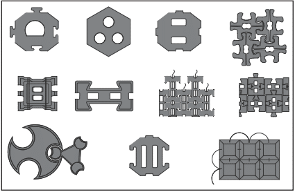
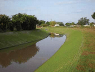
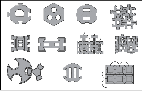
Articulating concrete block (ACB) revetment systems are used to provide erosion protection. The ACB system is a matrix of individual concrete blocks placed together to form an erosion-resistant revetment with or without a geotextile underlay for subsoil retention. General information on ACB systems can be found in ACB-TEC-001-14 Articulated Concrete Block for Erosion Control (ref. 1).

Proper installation of an ACB revetment system is essential to achieve suitable hydraulic performance and maintain stability against the erosive force of flowing water during the design hydrologic event. Quality workmanship is important throughout the installation, including subgrade preparation, geotextile placement, block system placement, backfilling and finishing, and inspection.

These guidelines apply to the installation of ACB revetment systems, whether hand-placed or placed as a mattress. They are based on Design Manual for Articulating Concrete Block (ACB) Revetment Systems (ref. 2) and comply with ASTM D6884, Standard of Practice for the Installation of Articulating Concrete Block (ACB) Revetment Systems (ref. 3). These guidelines do not purport to address the safety issues associated with installation of ACB revetment systems, including use of hazardous materials, mechanical equipment, and operations. It is the responsibility of the contractor to establish and adopt appropriate safety and health practices, and comply with prevalent regulatory codes, such as OSHA (Occupational Health and Safety Administration) regulations.

SOIL SAMPLES

When rough grading is complete, soil samples representative of the subgrade conditions should be obtained in accordance with the contract documents/project specifi cations or at a minimum frequency of one sample per 50,000 blocks, or additional fraction thereof, and tested for:

  1. particle size distribution (ASTM D422, ref. 4)
  2. Atterberg limits (ASTM D4318, ref. 5)
  3. Standard Proctor density (ASTM D698, ref. 6)

The system includes a geotextile underlay compatible with the subsoil that allows hydraulic infiltration and exfiltration to occur while providing particle retention. Granular filters may be used in place of, or in combination with, the geotextile per the engineer’s design drawings and specifications. When a granular filter is used, its gradation must meet the design gradation stated in the contract documents/project specification and should be tested for grain size distribution at the same frequency as the subgrade soil testing. Prior to placing the geotextile and ACB revetment system, laboratory test results must be submitted to the engineer to ensure conformance with design parameters.

SUBGRADE PREPARATION

Stable and compacted subgrade soil should be prepared to the lines, grades and cross sections shown on the contract drawings. Termination trenches and transitions between slopes and embankment crests, benches, berms, and toes should be compacted, shaped and uniformly graded to facilitate intimate contact between the ACB revetment system and the underlying grade. Secure the revetment in a manner that prevents soil migration when the ACB matrix is terminated at a structure, such as a concrete slab or wall.

Subgrade soil should be approved by the engineer to confirm that it meets the required material and compaction standards. Soils not meeting the required standards should be removed and replaced with approved material, as specified by the project specification or the engineer.

Care should be taken not to excavate below the grades shown on the contract drawings, unless directed by the engineer. Subgrade excavation above the water line should not be more than 2 in. (51 mm) below the grade indicated on the contract drawings. Subgrade excavation below the water line should not be more than 4 in. (102 mm) below the grade indicated on the contract drawings.

Where such areas are below the allowable grades, they should be brought to grade by placing approved material and compacting in lifts not exceeding 6 in. (152 mm) in thickness. Where it is impractical, in the opinion of the engineer, to dewater the area to be filled, over-excavations should be backfilled with crushed rock or stone conforming to the grading and quality requirements of well-graded coarse aggregate in ASTM C33, Standard Specification for Concrete Aggregates (ref. 7), or as directed by the engineer.

Where such areas are above the allowable grades, they should be brought to grade by removing material, or reworking existing material, and compacting as directed by the engineer.

When preparing dry areas to receive the ACB system, the surface should be graded smooth to ensure intimate contact between the subgrade surface and the geotextile and between the geotextile and the bottom surface of the ACB revetment system. Unsatisfactory soils, soils too wet to achieve desired compaction, and soils containing roots, sod, brush or other organic materials, should be removed, replaced with approved material and compacted. The subgrade should be uniformly compacted to a minimum 90 percent of the Standard Proctor density (ASTM D698) or as required by the project specification, whichever is more stringent. Should the subgrade surface for any reason become rough, eroded, corrugated, uneven, textured or traffic marked prior to ACB installation, such unsatisfactory portion should be scarified, reworked, recompacted or replaced as directed by the engineer.

The subgrade should be raked, screeded or rolled by hand or machine to achieve a smooth compacted surface that is free of loose material, clods, rocks, roots or other materials that would prevent satisfactory contact between the geotextile and the subgrade.

Immediately prior to placing the geotextile and ACB system, the prepared subgrade should be inspected and approved by the engineer.

GEOTEXTILE PLACEMENT

The geotextile should be placed directly on the prepared subgrade, in intimate contact with the subgrade and free from folds or wrinkles. The geotextile must be placed such that placement of the overlying materials will not excessively stretch or tear the geotextile.

The geotextile should be placed so that the upstream strips of fabric overlap downstream strips, and so that upslope strips overlap down-slope strips. Overlaps should be in the direction of flow wherever possible. Geotextile joints should be overlapped a minimum of 3 ft (1 m) for below-water installations and a minimum 1 ½ ft (0.5 m) for dry installations in accordance with ASTM D6884 (ref. 3). When a sewn seam is used for seaming of woven geotextile, the thread should be high-strength, UV-resistant polypropylene or polyester.

When a granular filter is used, the geotextile should be placed to encapsulate the granular filter as shown in Figure 1. The distance between encapsulation points should not exceed 20 ft (6 m). The geotextile should extend to the edge of the revetment within the top, toe and side termination points of the revetment. If necessary to expedite construction and to maintain the recommended overlaps, anchoring pins or 11 gauge, 6- by 1-in. (152 by 25 mm) U-staples may be used; however, weights (e.g., sand-fi lled bags) are preferred to prevent creating holes in the geotextile.

After geotextile placement, the work area should not be disturbed so the intimate contact between the geotextile and the subgrade is maintained. The geotextile should not be left exposed longer than the manufacturer’s recommendation, to minimize damage due to ultraviolet radiation.

ACB SYSTEM PLACEMENT

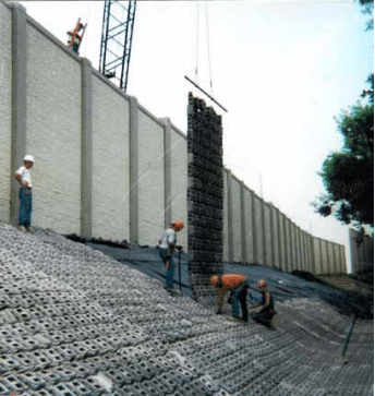
The articulating concrete block system should be placed on the geotextile in such a manner as to produce a smooth plane surface in intimate contact with the geotextile. For blocks within the mat and blocks that are hand set, the joint spacing between adjacent blocks must be maintained to prevent binding of blocks and to achieve block-to-block interlock.

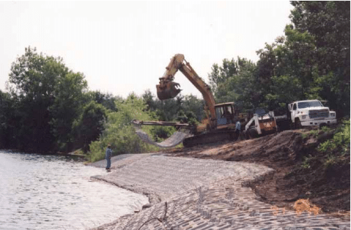
In curvature and grade change areas, alignment of the individual block and the orientation of the adjacent block must provide for intimate block-to-fabric contact and block-to-block interlock. Care should be taken during block installation to avoid damage to the geotextile or subgrade. When a geotextile is used, the ACB system placement should preferably begin at the upstream end and proceed downstream to minimize undermining of the revetment system if flows occur before installation is complete. If the ACB system is to be installed from downstream up, a contractor option is to place a temporary toe on the front edge of the ACB system to protect against undermining when flows are anticipated.

On sloped sections, when practical, placement should begin at the toe of the slope and proceed up the slope. Block placement should not bring block-to-block interconnections into tension. Individual blocks within the plane of the finished system must not exceed the protrusion tolerance used in the stability design of the system. The typical protrusion tolerance is ½ in. (13 mm).

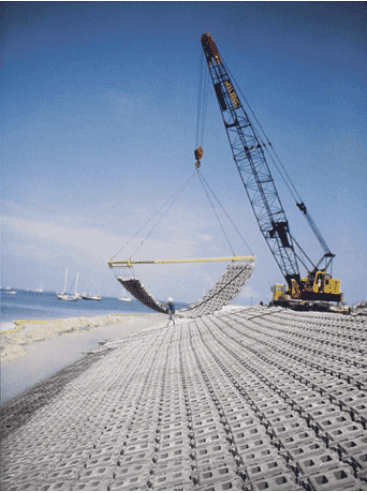
If assembled and placed as large mattresses, the articulating mats can be attached to a spreader bar to aid in lifting and placing the mats into their proper positions using a crane. The mats should be placed side-by-side and/or end-to-end so the mats abut each other. Mat seams or openings between mats greater than 2 in. (51 mm) between blocks should be filled with grout.

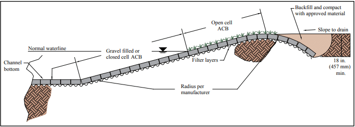
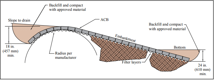
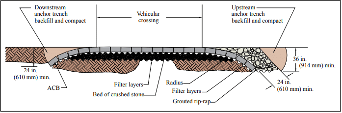
Whether ACBs are placed by hand or in large mattresses, distinct grade changes should be accommodated with a well-rounded transition (i.e., minimum radius determined by individual system characteristics). Figure 2 shows a conceptual detail of a minimum radius for a top and toe-of-slope transition for bed and bank protection, while Figure 3 shows a top-of-slope transition and a typical toe detail for bank protection. Conceptual details for additional conditions are illustrated in Design Manual for Articulating Concrete Block (ACB) Revetment Systems (ref. 2).

If a discontinuous revetment surface exists in the direction of flow, a grout seam at the grade change location should be provided to produce a continuous, flush-finished surface. Grout seams should not be wider than one-half the maximum dimension of a single block.

Termination trenches should be backfilled with approved fill material and compacted flush with the top of the blocks. The integrity of a soil trench backfill must be maintained to ensure a surface that is flush with the top surface of the ACBs throughout the entire service life. Top, toe and side termination trenches should be backfilled with suitable fill material and compacted immediately after the block system has been placed.

Anchors or other penetrations through the geotextile should be grouted or otherwise repaired in a permanent fashion to prevent migration of subsoil through the penetration point.

Do not use the ACB revetment system as a road for heavy construction traffic unless it is designed as a flexible pavement that can handle the expected wheel loads. Light traffic, such as single axle trucks and mowing equipment, may operate on installed ACB systems.

FINISHING

The open area of the articulating concrete block system is typically either backfilled with suitable soil for revegetation or with – to ¾-in. (9.5 to 19 mm) diameter uniform crushed stone, or a mixture thereof. Crushed stone can enhance the interlock restraint, but can make the ACB revetment system less flexible. Backfilling with soil or granular fill within the cells of the system should be completed as soon as possible after the revetment has been installed. When topsoil is used as a fill material above the normal waterline, overfilling by 1 to 2 in. (25 to 51 mm) may be desirable to allow for consolidation.

INSPECTION

Each step of installation—subgrade preparation, geotextile and granular filter placement, ACB revetment placement, and the overall finished condition, including termination points, should be inspected and approved by the engineer.

REFERENCES

  1. Articulated Concrete Block for Erosion Control, ACB-TEC-001-14, Concrete Masonry & Hardscapes Association, 2014.
  2. Design Manual for Articulating Concrete Block (ACB) Revetment Systems, ACB-MAN-001-20, Concrete Masonry & Hardscapes Association, 2020.
  3. Standard Practice for Installation of Articulating Concrete Block (ACB) Revetment Systems, ASTM D6884-03. ASTM International, Inc., 2003.
  4. Standard Test Method for Particle-Size Analysis of Soils, ASTM D422-63(2002). ASTM International, Inc., 2002.
  5. Standard Test Methods for Liquid Limit, Plastic Limit, and Plasticity Index of Soils, ASTM D4318-05. ASTM International, Inc., 2005.
  6. Standard Test Methods for Laboratory Compaction Characteristics of Soil Using Standard Effort (12,400 ft-lbf/ft³ (600 kN-m/m³), ASTM D698-00ae1. ASTM International, Inc., 2001.
  7. Standard Specification for Concrete Aggregates, ASTM C33-03. ASTM International, Inc., 2003.

ACB Revetment Design— Factor of Safety Method

INTRODUCTION

This Tech Note is intended to help designers understand the ACB design methodology and the different variables influencing the design and safety factor selection. Articulating concrete block (ACB) systems provide erosion protection to soil exposed to the hydraulic forces of moving water. ACB systems are a matrix of individual concrete blocks placed closely together to form an erosion-resistant overlay with specific hydraulic performance characteristics. Because it is composed of individual units, the ACB system can conform to minor changes in the subgrade without loss of intimate contact. Systems may be connected through geometric interlock and/or other components such as cables. Systems with openings in the blocks can typically be vegetated to provide a “green” channel and facilitate infiltration/exfiltration of channel moisture. Figure 1 illustrates a variety of ACB systems, but is not all-inclusive of available systems.

ACB units are concrete block produced in accordance with Standard Specification for Materials and Manufacture of Articulating Concrete Block (ACB) Revetment Systems, ASTM D6684 (ref. 1). Units must conform to minimum compressive strength, absorption and geometric specifications tested in accordance with Standard Test Methods for Sampling and Testing Concrete Masonry Units and Related Units, ASTM C140 (ref. 2).

This Tech Note addresses the structural stability of ACB revetment systems as a function of site-specific hydraulic conditions and unit characteristics. This Tech Note does not address geotextile filter and/or subgrade filter design, minimum installation guidelines critical to the proper performance of ACB revetments, or minimum upstream or downstream toe treatments. These topics are covered in design manuals such as references 5 and 6.

FACTOR OF SAFETY METHOD

Similar to many rip rap sizing methods, the Factor of Safety method quantifies hydraulic stability of ACB systems using a “discrete particle” approach (see ref. 7). The design method involves balancing the driving and resisting forces, including gravity, drag and lift as illustrated in Figure 2. In typical channel and spillway applications, failure due to sliding (slipping) of the ACB revetment along the bed is remote. The revetment system is more apt to fail as a result of overturning about the downstream edge of the ACB unit, or downstream corner point when the ACB unit is located on the side slope of a steep channel. For cases where the revetment is placed on steep side slopes (2H:1V or steeper), the design should evaluate the potential for slip shear failures along geosynthetic-ACB unit interfaces induced by hydraulic and gravitational forces (i.e., potential slope instability).

Fundamental principles of open channel flow and rigid body mechanics are used along with hydraulic test results supplied by manufacturers. The size and weight of the ACB units, as well as performance data from full-scale laboratory testing, are considered in evaluating the ratio of resisting to overturning moments (the “force balance” approach). This ratio defines the factor of safety against uplift. The design procedure accounts for additional forces applied to the unit when protrusions above the matrix occur, such as subgrade irregularities or due to improper placement (see Figure 3). Failure is defined as loss of intimate contact between the ACB unit and subgrade. The effects of cables or rods, vegetative root anchorage or mechanical anchorage devices are conservatively ignored.

Target Factor of Safety

There are several factors that need to be understood and considered when evaluating the appropriate target safety factor for design purposes. These can be categorized into two groups; external and internal factors. The external group consists of factors such as the complexity of the hydraulic system, the uncertainty of the input hydraulics, and the overall consequence of failure. These uncertainties are accounted for in the design by incorporating them into the target safety factor.

As discussed below, there are multiple facets of the safety factor methodology that are considered as they relate to external and internal design factors.

External Factors
  1. Complexity of the hydraulic system and uncertainty of the input hydraulics.
    All hydraulic systems are not of the same complexity. Modeling the flow characteristics of a stream bank or channel is much different than the design of scour protection around bridge piers. If the flow is relatively uniform and predictable, then the designer may select a lower value for the target safety factor. As the complexity of the system increases, so too should the sophistication of the model used to determine the hydraulic parameters. Utilizing a simplistic model in a complex environment may warrant an increase in the target safety factor (i.e., greater than 1.5). Conversely, if a complex model is used to analyze a simplistic design scenario, then a lower target safety factor may be adequate (i.e., less than 1.5).
  2. Consequence of failure.
    As with the complexity of the hydraulic system, the overall consequence of failure needs to be understood. Failure that results in loss of life is much different from a failure resulting in soil erosion along a stream bank in which no loss of life or property is imminent. Increasing the target safety factor is one way of potentially offsetting environmental conditions that are considered high risk.
Internal Factors
  1. Extrapolation of Test Data.
    In order to use the safety factor methodology, the critical shear stress of the unit along a horizontal surface must be understood and quantified. An equation is used for the extrapolation of test results from a steeper bed slope to a horizontal slope. A second extrapolation takes place from the tested units to thicker, untested units. In both processes, it is assumed that the intra-block restraint is the same for all thicknesses of the units. Under this assumption, the extrapolation equations only consider the weight and thickness of the units. This moment balance approach (obtained from the geometry of the unit) neglects any intra-block restraint. This assumption can be very conservative given the fact that thicker units have much more intra-block friction than thinner units given the shape of the blocks. As illustrated in Figure 4, the bottom half of an ACB unit is essentially a rectangle of concrete with adjacent units resting against six surrounding units (because the units are placed in a running bond pattern, there are six adjacent units, rather than four). As the unit increases in thickness, so too does the intra-block friction. Currently, the safety factor methodology does not account for this variable, which only increases the conservatism of this design approach for such conditions.
  2. Performance Values.
    Hydraulic testing on different “footprint” or classes of blocks and tapers for a variety of dam overtopping and spillway applications has been performed by system manufacturers. In many of these tests, the testing facility was unable to fail the system under a 4 ft (1.2 m) and 5 ft (1.5 m) overtopping scenario. Nevertheless, the resulting shear stresses obtained from the tests are used within the safety factor methodology as a threshold, or failure, shear stress. This issue is compounded when extrapolating to thicker units. Without being able to reach a threshold condition in the testing flume, licensors and manufacturers extrapolate shear stress value from a stable value. A large degree of conservatism in the performance values of the units is the result of not being able to fail these systems under laboratory conditions.
  3. Interaction between Velocity and Shear Stress.
    In flume testing of the units (see Fig. 5), two of the most important results obtained are: a stable shear stress; and, velocity at a downstream point under the highest flow conditions.Consider for example testing results whereby the highest boundary shear stress and velocity obtained was 22.2 lb/ft² (1,063 Pa) and 26.1 ft/s (7.96 m/s), respectively. In the safety factor methodology one utilizes a shear stress of 22.2 lb/ft² (1,063 Pa) regardless of the expected design velocity for every design utilizing this particular unit (provided that the design velocity is less than or equal to the tested velocity). Common “hydraulic” sense would state that if the velocity was only 12 ft/s (3.66 m/s) for a given application, then the system could withstand a much larger shear stress than 22.2 lb/ft² (1,063 Pa). Therefore, an additional degree of conservatism is present when the design velocity is less than the tested velocity and the design utilizes the maximum shear stress generated during the higher velocity event.
  4. Allowable shear stress in a vegetated state.
    All of the testing on existing ACB systems has taken place in a non-vegetated state. In contrast, many ACB applications for overtopping and spillway applications seek a final system that is fully vegetated. A series of hydraulic tests conducted by the U.S. Army Corp of Engineers investigated the performance of identical ACB systems in both vegetated and non-vegetated conditions (ref. 14). The end result was an increase in the allowable shear stress of 41% when vegetated.

Taking into consideration all of the points addressed above, what is the proper target safety factor required for a dam overtopping or spillway application? It is safe to state that the methodology used for ACB design is full of conservative assumptions. From the fact that tapered ACB systems have not reached their threshold condition in the testing flume to the fact that vegetation increases the allowable shear stress, it is apparent that the resulting safety factor can be conservative by 20 – 50%. Therefore, a target safety factor of 1.3 – 1.5 is adequate for applications in which the design hydraulics and site geometry are clearly understood, such as dam overtopping or spillway applications. Ultimately, the “external” factors and overall design of the project will need to be evaluated and decided on by the engineer of record. It may also be appropriate for an individual experienced in ACB design to offer an opinion on how these factors should be incorporated into an overall target safety factor.

Hydraulic Considerations

The main hydraulic variable in ACB stability design is the total hydraulic load (or bed shear stress) created by a varying discharge within a fixed geometric cross-section. The ratio of designed average cross-sectional bed shear to the ACB’s critical shear value (obtained from testing) is used, in part, for practical analysis and evaluation of ACB stability. The cross-section averaged bed shear stress, τo, can be calculated for design using a simple equation (ref. 13):

τo = γ R Sf

τo is applied over the channel boundary, regardless of o channel lining. Shear stress is a function of the hydraulic radius and the slope of the energy line (for the simplest case—the bed slope), both defined by channel geometry and flow conditions.

The cross-section averaged bed shear stress is suitable for uniform flow conditions such as those found in long straight reaches of open channels with uniform cross section. It may be determined using simplified model approaches, such as the Manning equation or the HEC-RAS model (ref. 11). For cases involving bends, confluences, constrictions and flow obstructions, more sophisticated hydraulic modeling is generally appropriate, such as a two-dimensional model which can evaluate time-dependent flow conditions or complex geometry (ref. 10).

Design velocity is often determined using the Manning Equation for steady uniform flow as follows (ref. 13):

An iterative process is used to determine the flow depth, yo, because both the area and hydraulic radius are functions of yo. Cross-sectional averaged velocity of flow is then defined as V = Q/A. As noted previously, complex hydraulic systems require sophisticated modeling to determine averaged velocity.

The cross-sectional averaged bed shear stress and cross sectional averaged velocity should be determined by a design professional familiar with hydraulic design practices.

ACB Revetment Considerations

Historically, manufacturers of ACB systems published performance data from full-scale tests performed in accordance with Federal Highway Administration guidelines (ref. 8). Two relatively new ASTM standards have been developed based on the FHWA method: Standard Guide for Analysis and Interpretation of Test Data for Articulating Concrete Block (ACB) Revetment Systems in Open Channel Flow, ASTM D7276 (ref. 3) and Standard Test Method for Performance Testing of Articulating Concrete Block (ACB) Revetment Systems for Hydraulic Stability in Open Channel Flow, ASTM D7277 (ref. 4), that eventually will replace the FHWA test method. This data provides the critical shear stress, τc, and is based on specific flow conditions and ACB system characteristics. The manufacturer should specify whether the critical shear stress is for a unit on a horizontal surface or on an inclined surface. Values for a unit on a horizontal surface are commonly specified. It is important that the designer consider the full-scale test configuration and hydraulic conditions used to derive the critical shear stress on a horizontal surface.

Testing involves the construction of a full-scale test embankment that is subsequently exposed to hydraulic load until failure—defined as the local loss of intimate contact between the ACB unit and the subgrade it protects. A schematic of a typical flume is illustrated in Figure 5. ACB system stability is evaluated by summing the driving and resisting moments about the toe of an individual ACB unit. The inter-block restraint, FR, is ignored, as is any contribution from cables, anchorages and vegetation (see Figure 2).

ACB placement or subgrade irregularities can result in one unit protruding above the ACB matrix, as shown in Figure 3. The protrusion height, ΔZ, is a function of installation practice and block-to-block interface, and is often assumed to be ¼ to ½ in. (6 to 13 mm). However, the designer must consider site-specific conditions and adjust ΔZ as required. The lift force, F’L, resulting from the protrusion is conservatively assumed equal to the drag force, F’D.

The established design methodology assumed that the flow was parallel to the block and calculated the drag forces using the block width perpendicular to the flow, b (see equation for F’D in Table 1 and Figure 6b). However, in the field not all ACB applications have the flow aligned with the sides of the block. To account for that uncertainty, it is recommended that the diagonal distance of the block, 2l2, be used instead of b in the drag force calculations (see Figure 6b). It is recommended that the designer analyze the project conditions and determine the appropriate dimension for determining the drag forces, F’D, and safety factors on each project. Examples of non-parallel flow conditions are open channels and levees where the flow alignment is uncertain during the life of the project.

The factor of safety against loss of intimate contact is considered to be a function of design bed shear stress, critical shear stress, channel geometry and ACB unit geometry and weight. Figure 2 illustrates unit moment arms based on unit geometry. The safety factor for a single ACB unit is determined from the ratio of restraining moments to overturning moments. Considering the submerged unit weight, WS, unit moment arms and drag and lift forces, the safety factor, SF is defined as (ref. 6):

Dividing by l1WS and substituting terms, the equation for SF resolves to that presented in Table 1. Table 1 also outlines the calculations necessary for determining factor of safety.

DESIGN EXAMPLE

A trapezoidal channel section with 3H:1V side slopes (Z = 3, θ1 = 18.4°) and a base width b of 15 ft (4.6 m) requires stabilization. The 100-year design discharge is 450 ft³/s (12.7 m³/s), and the channel slope So is 0.03 ft/ft (0.03 m/m) (θ0 = 1.72°). The channel has a uniform bed and no flow obstructions (i.e. confluences, bends or changes in geometry). Manning’s n is specified as 0.035. Based on design conditions, the energy grade line Sf is assumed equal to the channel slope So.

Step 1 Determine flow depth and cross-sectional averaged velocity:

R = A/P, hydraulic radius

By iteration, the flow depth yo is determined to be 2.1 ft (0.6 m).

Step 2 Calculate design shear stress:

Step 3 Select target factor of safety:
Based on the analysis of the project conditions, such as type of application, low consequence of failure and the empirical hydraulic model, the designer has recommended a target factor of safety, SFT, for the project of 2.34.

Step 4 Select potential ACB product and obtain geomorphic and critical shear stress data:
The proposed ACB manufacturer specifies a critical shear stress, τc, for the unit on a horizontal surface of 30 psf (1.4 kPa) for a maximum velocity of 20 ft/s (6.1 m/s), submerged unit weight of 38 lb (17.2 kg) and dimensions of 15 (w) x 18 (l) x 5 (h) in. (381 x 457 x 127 mm).

Step 5 Calculate factor of safety against incipient unit movement:
Given;
Ws = 35 lb (16 kg)
bu = 1.5 ft (460 mm)
τc = 30 psf (1.4 kPa)
ηo = 2.96/30 = 0.0987

and determining the following geometrically (see Figure 6);

and assuming (see discussion);
ΔZ = 0.0417 ft (13 mm)

the following are calculated using the equations in Table 1:

For this open channel application the flow is not considered to align with the block, so b = 2l2
aθ = 0.948
θ = 5.16°
β = 19.4°
η1 = 0.08
δ = 65.4°
SF = 2.43

Because the calculated factor of safety exceeds the target, the proposed ACB system is stable against loss of intimate contact.

An ACB Design Spreadsheet (ref. 15) that makes these calculations much easier is available free on request via the CMHA  web site.

NOTATIONS:

A = cross-sectional flow area, ft² (m²)
aq = projection of Ws into subgrade beneath block (Table 1)
b = width of channel base, ft (mm)
bu = width of ACB unit in the direction of flow, ft (mm)
FD = drag force, lb (kN)
F’D = additional drag forces, lb (kN)
FL = lift force, lb (kN)
F’L = additional lift forces, lb (kN) (Table 1)
FR = inter-block restraint, lb (kN)
lx = block moment arms, ft (mm)
n = Manning’s roughness coefficient
Q = design discharge, ft³/s (m³/s)
R = hydraulic radius (A/wetted perimeter), ft (m)
SC = specific gravity of concrete (assume 2.1)
Sf = energy grade line, ft/ft (m/m)
So = bed slope, ft/ft (m/m)
SF = calculated factor of safety (Table 1)
SFT = target factor of safety
V = cross-sectional averaged flow velocity, ft/s (m/s)
W = weight of block, lb (kg)
Ws = submerged weight of block, lb (kg) (Table 1)
Ws1 = gravity force parallel to slope, lb (kN)
Ws2 = gravity force normal to slope, lb (kN)
yo = flow depth, ft (m)
Z = horizontal to vertical ratio of channel side slope
β = angle of block projection from downward direction, once in motion, degrees or radians
γ = unit weight of water, 62.4 pcf (1,000 kg/m³)
ΔZ = height of block protrusion above ACB matrix, ft (mm)
δ = angle between drag force and block motion, degrees or radians
ηo = stability number for a horizontal surface (Table 1)
η1 = stability number for a sloped surface (Table 1)
θ = angle between side slope projection of WS and the vertical, degrees or radians (Table 1)
θ0 = channel bed slope, degrees or radians
θ1 = channel side slope, degrees or radians
ρ = mass density of water, 1.94 slugs/ft³ (1,000 kg/m³)
τc = critical shear stress for block on a horizontal surface, lb/ft² (kPa)
τdes = design shear stress, lb/ft² (kPa)
τo = cross-section averaged bed shear stress, lb/ft² (kPa)

REFERENCES

  1. Standard Specification for Materials and Manufacture of Articulating Concrete Block (ACB) Revetment Systems, ASTM D6684-04(2010). ASTM International, 2010.
  2. Standard Test Methods for Sampling and Testing Concrete Masonry Units and Related Units, ASTM C140-09. ASTM International, 2010.
  3. Standard Guide for Analysis and Interpretation of Test Data for Articulating Concrete Block (ACB) Revetment Systems in Open Channel Flow, ASTM D7276-08. ASTM International, 2010.
  4. Standard Test Method for Performance Testing of Articulating Concrete Block (ACB) Revetment Systems for Hydraulic Stability in Open Channel Flow, ASTM D7277-08. ASTM International, 2010
  5. Design Manual for Articulating Concrete Block Systems. Harris County Flood Control District, Houston, Texas, 2001.
  6. Design Manual for Articulating Concrete Block, ACBMAN-001-20. Concrete Masonry & Hardscapes Association, 2020.
  7. Bridge Scour and Stream Instability Countermeasures: Experience, Selection, and Design Guidance – 3rd Edition. Federal Highway Administration Hydraulic Engineering Circular No. 23.
  8. Clopper, P. E. and Y. Chen. Minimizing Embankment Damage During Overtopping Flow, Technical Report FHWA RD-88-181. Federal Highway Administration, 1988.
  9. Clopper, P. E. Hydraulic Stability of Articulated Concrete Block Revetment Systems During Overtopping Flow, Technical Report FHWA RD-89-199. Federal Highway Administration, 1989.
  10. RMA2 Version 4.5. United States Army Corps of Engineers. USACE Waterways Experiment Station, 2008.
  11. HEC-RAS Version 4.1. United States Army Corps of Engineers. USACE Hydrologic Engineering Center, 2010.
  12. Articulated Concrete Block for Erosion Control, ACBTEC-001-14, Concrete Masonry & Hardscapes Association, Herndon, Virginia, 2014.
  13. Morris, H. M. and J. Wiggert. Applied Hydraulics in Engineering, Second Edition, James Wiley & Sons, 1972.
  14. Lipscomb, C.M, C.I. Thornton, S.R. Abt, and J. R. Leech. Performance of Articulated Concrete Blocks in Vegetated and Un-Vegetated Conditions. Proceedings of the International Erosion Control Association 32nd Annual Conference and Exposition, Las Vegas, NV, February 5-8, 2001.
  15. Articulating Concrete Block (ACB) Design Spreadsheet, ACB-XLS-001-19. Concrete Masonry & Hardscapes Association, Herndon, Virginia, 2019.

Articulating Concrete Block for Erosion Control

INTRODUCTION

An articulating concrete block (ACB) system is a matrix of individual concrete blocks placed together to form an erosion-resistant overlay with specific hydraulic performance characteristics. The system includes a filter layer underlay that allows infiltration and exfiltration to occur while providing particle retention of the soil subgrade. The filter layer may be comprised of a geotextile or properly graded aggregate or both. The blocks within the matrix must be dense and durable while providing a matrix that is flexible and porous.

Articulating concrete block systems are used to provide protection to underlying soil materials. The term “articulating” implies the ability of individual blocks of the system to conform to changes in subgrade while remaining interlocked or otherwise restrained by virtue of the block geometric interlock and/or additional system components such as cables, ropes, geotextiles, or geogrids. The interlocking property provided by the special shapes of ACBs also allows for expansion and contraction. Long-term durability and sustainability relies on an appropriate engineered design based on site-specific hydrological and geotechnical conditions. They are either hand-placed or installed as pre-assembled mats on top of a filter layer on prepared subgrade, and act as a soil revetment.

Articulating concrete blocks (ACBs) are an effective erosion control system used to solve a wide variety of erosion problems:

  • drainage channels
  • wildlife habitat
  • river fronts
  • bridge abutments/piers
  • coastal shorelines
  • dikes and levees
  • pipeline protection
  • spillways
  • boat ramps
  • retention basins
  • lake shorelines
  • overflow channels
  • low water crossings
  • dam overtopping

The systems are easy to install, simple to produce, and environmentally friendly. ACB systems are often used as an alternative to cast-in-place concrete bulkheads and slope paving, gabions, soil cement, roller compacted concrete, or rock riprap. ACBs can also be used as grid pavers. However, grid pavers manufactured according to ASTM C1319, Standard Specification for Concrete Grid Paving Units (ref. 7), are not considered ACBs.

Articulating concrete blocks are produced in accordance with ASTM D6684, Standard Specification for Materials and Manufacture of Articulating Concrete Block (ACB) Revetment Systems (ref. 3). They can be made in a variety of shapes and thicknesses, and may even be colored according to preference. ACBs have excellent resistance to hydraulic shear and overtopping conditions. Design resources for ACBs include the Design Manual for Articulating Concrete Block and ACB Design Spreadsheet (refs. 2, 8).

ENVIRONMENTAL BENEFITS

One of the environmental benefits of ACB erosion systems is that vertical cores and spaces can be incorporated throughout the system, which allows vegetation growth. Properly selected plant species can almost completely cover the entire hard surface of the ACBs, allowing them to blend in with the natural look of the project as well as water purification by absorbing nutrients and breaking down other pollutants. During peak storm events, the ACB layer beneath the vegetation will protect the soil from erosion. The ability to support the ecosystem’s habitat is a major advantage of ACB systems over other erosion control methods. Additional advantages of ACB systems are:

  • serviceability
  • aesthetics
  • pedestrian safety
  • sustainability
  • cost effectiveness
  • flexibility

The permeability of ACBs allows their use to preserve natural drainage and treatment systems. ACBs installed on filter media are pervious surfaces that reduce water runoff and flooding risks, improve water quality, reduce pollutants, recharge aquifers and prevent erosion. These environmental characteristics permit the use of ACBs on sustainable developments to preserve or improve existing sites and can be applicable to credits in some green building rating systems, such as LEEDTM, which is discussed in more detail below.

ACBs installed over drainage layers can also be used in a Best Management Practices (BMP) plan to preserve or improve existing sites, or in new developments. The system installed over a drainage layer preserves the natural drainage and treatment systems of the soil, reducing water runoff and flooding risks, improving water quality, reducing pollutants, recharging aquifers, and preventing erosion. Research on permeable pavers that are installed in a similar manner to ACBs (block over a gravel drainage layer) has also shown a promotion of aerobic biodegradation of hydrocarbons and reduction of nutrients (refs. 11, 12). When vegetated, they can also generate habitat. These qualities make ACBs a great solution for use in sustainable projects where water quantity and quality control are extremely important.

LEED Certification

ACBs can also make a significant contribution to project certification under Leader in Energy and Environmental Design (LEED) registered projects. Under LEED v3 for New Construction (ref. 9), ACB products can help attain points toward certification in the following categories: Sustainable Sites, Materials & Resources, and potentially Innovation in Design and Regional Priority Credits. These are briefly discussed below, based on LEED v3 for New Construction. Other versions of LEED may have different credit numbers, or slightly different criteria. For more detailed information on ACB’s potential contributions towards LEED credits, see TEK 06-09C, Concrete Masonry and Hardscape Products in LEED 2009 (ref. 10).

Sustainable Sites: ACBs can help capture up to 5 credits of the 26 possible in the following areas:

  • Prerequisite—The project is required to reduce the pollution generated during construction. ACBs can contribute to preventing erosion, reducing dust when working as drivable surfaces, and constructing sediment basins with the added support for vegetation growth that increases water quality.
  • Credit 5.1, Protect or Restore Habitat—ACBs can be used to restore erosion-prone areas by retaining soil and promoting plant growth.
  • Credit 5.2, Maximize Open Spaces—Ponds constructed with ACBs may count as open space as long as they are vegetated and meet the maximum 1:4 (vertical : horizontal) side slope limit.
  • Credit 6.1, Storm Design: Quantity Control—Using ACBs can reduce a site’s impermeable hardscaping for slope stability and erosion control, allowing stormwater to percolate into the ground and reducing runoff. In addition, receiving channels protected with ACBs can reduce erosion, reduce impervious surfaces and, when planted, contribute to the overall aesthetics and ecology.
  • Credit 6.2, Storm Design: Quality Control—ACBs can also be used to reduce the amount of stormwater that requires treatment. As discussed above under Environmental Benefits, ACBs on gravel filters have been shown to improve runoff quality.
  • Credit 7.1, Heat Island Effect: Non Roof—Open grid ACBs (at least 50% pervious) or with a Solar Reflectance Index (SRI) of at least 29 can be used in lieu of traditional concrete or asphalt to reduce the urban heat island effect.

Materials and Resources: ACBs can contribute towards 8 of the 14 possible credits in the following areas:

  • Credit 2, Construction Waste Management— Damaged concrete products can be redirected to the manufacturing process for recycling and unused products can be reused on another project.
  • Credit 3, Material Reuse—ACBs can potentially be salvaged from one project and reused in another.
  • Credit 4, Recycled Content—Concrete products, including ACBs, can be manufactured using recycled materials that have been diverted from the waste stream.
  • Credit 5, Regional Materials—Concrete hardscape products are usually available close to the point-of-use and are manufactured with local materials.

Innovation in Design: Projects can earn Innovation in Design credits by exceeding the LEED credit requirements, or by addressing innovative environmental strategies not specifically addressed in LEED, such as the life cycle environmental impact of the materials used.

Regional Priority Credits: Up to 4 LEED credits can be earned through Regional Priority Credits, which are designed to encourage designers to focus on specific regional needs. The credits are classified by zip code and designers have the option to excel in aspects of the project that are priorities in their region. ACBs could contribute to attain higher percentages on all the credits mentioned above to qualify for extra points.

ACB UNITS

ACB units complying with ASTM D6684, Standard Specification for Materials and Manufacture of Articulating Concrete Block (ACB) Revetment Systems (ref. 3), are produced as dry-cast (in a block machine) or wet-cast (with concrete and molds). Sampling and testing of dry-cast ACB units are performed in accordance with ASTM C140, Standard Test Method for Sampling and Testing Concrete Masonry Units and Related Units (ref. 6), for conformance with the requirements in Table 1. Sampling and testing of wet-cast units is performed in accordance with ASTM C39, Standard Test Method for Compressive Strength of Cylindrical Concrete Specimens and ASTM C42, Standard Test Method for Obtaining and Testing Drilled Cores and Sawed Beams of Concrete (refs. 4, 5).

Several varieties of ACB systems are available: interlocking, cable-tied and non-cable-tied matrices, and open cell and closed cell varieties. Open cell units contain open voids within individual units that facilitate the placement of aggregate and/or vegetated soil. Closed cell units are solid concrete elements that are capable of allowing vegetation growth between adjacent units. Figure 1 shows a variety of ACB units in plan view.

ACB INSTALLATION

Articulating concrete blocks can be installed by small construction crews with a modest amount of equipment. Installations are fast and are easy to inspect due to the visibility of all components.

ACBs are installed on top of a filter layer over a prepared subgrade. The filter acts to protect and hold the subgrade in place while allowing bidirectional water penetration. Final subgrade elevation should be 0 to + ½ in. (12.7 mm) under a 10 ft. (3.05 m) straight edge. After the ACB installation is complete, the open cell voids or joints between the ACB units are filled with granular material or soil. Unit to unit vertical offset should be limited to the value utilized in the design. If vegetation is required, hydraulic seeding or mulching provides a low cost and highly effective method of establishing commonly used grasses and plants. In applications subject to continually flowing water, solid units should be used below the normal waterline or the voids of hollow units should be filled with gravel. Figures 2 through 4 show typical ACB cross-sections.

Installation methods depend on whether the ACB product being used is classified as cabled or as non-cabled.

Cabled Articulating Concrete Mats

Cabled interlocking blocks have preformed horizontal holes cast in them so that high-strength cables or ropes (synthetic or steel) can be installed through the matrix of blocks binding them into a monolithic mattress. The cables or ropes are used to facilitate placement of the mat, normally by a spreader bar and crane, as shown in Figures 5 and 6. For design purposes, cables offer no hydraulic stability or structural value to the ACB mat or block system.

The blocks are pre-assembled into cabled mats in a controlled environment on or off the job site. The mats are lifted by the cables’ end loops, placed on the back of a flatbed truck, and shipped to the job site where they are again lifted and placed on the prepared slope. The mats can also be fabricated on site near the prescribed area, eliminating the need for additional trucking. Assembly of the blocks into mats makes it possible to install these systems underwater and on steep slopes.

Several commercially available cable systems can be manually placed on a shoreline or channel, and the cables then hand-inserted through the holes. An advantage of this process is that revetments with fewer seams can be constructed. Also, it is easier to hand-place the blocks around a radius or projection on a sloped bank, such as a culvert outlet. To accomplish this with pre-assembled ACB mats, custom-shaped mats must be fabricated or field piece work insertions are required. Both require careful planning, detailing, and execution in the field.

Non-Cabled Articulating Concrete Mats

Non-cabled blocks are cast in interlocking shapes to provide a positively connected matrix that is individually hand-placed by semi-skilled labor. The blocks are individually installed according to the geometry of the product. The typical block layout is oriented in the application’s centerline position. These blocks make it possible to install ACBs in areas that are restrictive to large construction equipment.

ACBs without cables can be suited to projects where complex site geometries and limited access are present. These non-cabled ACBs offer comparable shear resistance and some systems offer a higher percentage of open surface area when desired. These blocks are typically delivered in palletized cubes and are hand-placed at the job site. Since there are no cables involved, the material costs can be considerably less. ACBs without cables can be constructed in virtually seamless fields.

DESIGN CONSIDERATIONS

Existing and proposed project characteristics combined with the hydraulic design objectives will determine, through a factor of safety analysis, the ACB product that will best serve the project’s erosion control needs. A 1.5 factor of safety is common.

Guidelines for the selection and design of the appropriate ACB product are provided by the Design Manual for Articulating Concrete Block (ref. 2) and TEK 11-12A, Articulating Concrete Block Revetment Design—Factor of Safety Method (ref. 1).

The hydraulic forces which are considered in the design of erosion control projects using this technology are hydraulic lift, drag, and impact. ACBs have demonstrated the ability to resist high velocity flows in excess of 25 ft/s (7.6 m/s), usually associated with drainage channels, water control structures, dam spillways, and fast flowing rivers. While many of the forces created by water can be readily calculated, particularly uplift and drag, each project application has separate design considerations.

ACBs are not designed to add structural strength to the slopes. The protected slope must be geotechnically stable prior to placement of surface protection. Known as “flexible revetments,” ACB installations should not be placed on slopes which are steeper than the natural angle of repose of the soil. This is a different technology than retaining walls which resist lateral earth pressures.

Protruding height variances between adjacent blocks should be minimized and must be in accordance with the design value utilized. Grading beneath the block and fabric is critical to establishing an acceptable finished profile of the ACBs.

Filter layers are always placed under the ACBs. The function of the filter is critical, as it must retain the soil in place while letting water pass through without clogging. The filter layer must remain in intimate contact with the block and the soil to preclude soil particles from being transported down the slope beneath the geotextile. The key design points to consider in the filter selection are:

  • Only woven monofilament or nonwoven needle-punched geotextiles should be considered for filter applications.
  • The filter layer must have a long-term permeability capable of handling the required volume of water through a restricted surface area equal to the joint area of the articulating concrete block.
  • The permeability of the filter layer must always be equal to or greater than the permeability of the protected soil unless a special bedding layer is provided.
  • The filter layer needs only to retain the majority of particles beneath it, thus creating a filter bridge.

Care should be taken in the specification of the underlying geotextile filter layer. Appropriate ASTM test methods are available to characterize soil properties and should be done to develop the retention criteria and proper permeability. The geotextile must possess adequate strength and endurance properties to survive the process of installation and any long-term forces applied to it. ASTM D6684, Standard Specification for Materials and Manufacture of Articulating Concrete Block (ACB) Revetment Systems (ref. 3), provides strength requirements for geotextiles.

In most of these designs, the owner or architect should rely upon the engineering expertise of a qualified engineer to select the appropriate block type, filter layer, soil compaction, and design parameters. Proper material selection and construction practices are required and should be checked during installation.

REFERENCES

  1. Articulating Concrete Block Revetment Design—Factor of Safety Method, ACB-TEC-002-11, Concrete Masonry & Hardscapes Association, 2002
  2. Design Manual for Articulating Concrete Block, ACB- MAN-001-20, Concrete Masonry & Hardscapes Association, 2020.
  3. Standard Specification for Materials and Manufacture of Articulating Concrete Block (ACB) Revetment Systems, ASTM D6684. ASTM International, 2018.
  4. Standard Test Method for Compressive Strength of Cylindrical Concrete Specimens, ASTM C39/C39M. ASTM International, 2021.
  5. Standard Test Method for Obtaining and Testing Drilled Cores and Sawed Beams of Concrete, ASTM C42/42M. ASTM International, 2020.
  6. Standard Test Method for Sampling and Testing Concrete Masonry Units and Related Units, ASTM C140. ASTM International, 2023A.
  7. Standard Specification for Concrete Grid Paving Units, ASTM C1319. ASTM International, 2021.
  8. ACB Design Spreadsheet
  9. Leadership in Energy and Environmental Design (LEED) Green Building Rating System, v3. United States Green Building Council, 2009.
  10. Concrete Masonry and Hardscape Products in LEED 2009, TEK 06-09C, Concrete Masonry & Hardscapes Association, 2009.
  11. Hunt, W.F., Collins, K.A., Hathaway, J.M. Hydrologic and Water Quality Evaluation of Four Permeable Pavements in North Carolina, USA. Proceedings of the 9th International Conference on Concrete Block Paving. Buenos Aires, Argentina, 2009.
  12. Kirkpatrick, R., Campbell, R, Smyth, J., Murtagh, J., Knapton, J. Improvement Of Water Quality By Coarse Graded Aggregates In Permeable Pavements. Proceedings of the 9th International Conference on Concrete Block Paving. Buenos Aires, Argentina, 2009.


Segmental Retaining Wall Units

INTRODUCTION

Mortarless segmental retaining walls are a natural enhancement to a variety of landscape projects. Applications range from 8 in. (204 mm) high terraces for erosion control to retaining walls 20 ft (6.1 m) or more in height. The individual concrete units can be installed to virtually any straight or curved plan imaginable.

Segmental retaining walls are used to stabilize cuts and fills adjacent to highways, driveways, buildings, patios and parking lots, and numerous other applications. Segmental retaining walls replace treated wood, cast-in-place concrete, steel, and other retaining wall systems because they are durable, easier and quicker to install, and blend naturally with the surrounding environment. Concrete units resist deterioration when exposed to the elements without the addition of toxic additives which can threaten the environment.

A variety of surface textures and features are available, including split faced, stone faced, and molded face units, any one of which may be scored, ribbed, or colored to fit any project application. Construction of segmental retaining walls does not require heavy equipment access, nor does the system require special construction skills to erect. Manufactured concrete retaining wall units generally weigh 30 to 100 lb (14 to 45 kg) each and are placed by hand on a level or sloped gravel bed.

Successive courses are stacked dry on the course below in the architectural pattern desired. Mechanical interlocking and/or frictional shear strength between courses resists lateral soil pressure. In low-height walls, overturning forces due to soil pressure are resisted by the weight of the units, sometimes aided by an incline toward the retained soil. Higher walls resist lateral soil pressures by inclining the wall toward the retained earth, or by other methods such as anchoring to geosynthetic reinforcement embedded in the soil. Further information on the design of segmental retaining walls can be found in Design Manual for Segmental Retaining Walls (ref. 1).

Segmental retaining wall units are factory-manufactured to quality standards in accordance with ASTM C1372, Standard Specification for Segmental Retaining Wall Units (ref. 2). These requirements are intended to assure lasting performance, little or no maintenance, structural integrity, and continued aesthetic value.

Segmental retaining wall units complying with the requirements of ASTM C1372 have been successfully used and have demonstrated good field performance. Segmental retaining wall units currently being supplied to the market should be produced in accordance with this standard so that both the purchaser and the supplier have the assurance and understanding of the expected level of performance of the product.

ASTM C1372 covers both solid and hollow units which are to be installed without mortar (dry-stacked). Units are designed to interlock between courses or to use mechanical devices to resist sliding due to lateral soil pressure. If particular features are desired, such as a specific weight classification, higher compressive strength, surface texture, finish, color, or other special features, they should be specified separately by the purchaser. However, local suppliers should be consulted as to the availability of units with such features before specifying them.

Materials

ASTM C1372 includes requirements that define acceptable cementitious materials, aggregates, and other constituents used in the manufacture of concrete segmental retaining wall units. These requirements are similar to those included in ASTM C90, Standard Specification for Loadbearing Concrete Masonry Units (ref. 3).

Compressive Strength

Minimum compressive strength requirements for segmental retaining wall units are included in Table 1. Units meeting or exceeding these strengths have demonstrated the integrity needed to resist the structural demands placed on them in normal usage. These demands include impact and vibration during transportation, the weight of the units above them in the wall, nonuniform distribution of loads between units, and the tensile stresses imposed as a result of typical wall settlement.

Segmental retaining wall units will not fail in service due to compressive forces since axial loads are only a result of self-weight. Due to the direct relationship between compressive strength and tensile strength, this minimum requirement is used to ensure overall performance.

Compressive strength testing of full size units is impractical due to the large size and/or unusual shape of some segmental retaining wall units. Therefore, compressive strength of these units is determined from testing coupons cut from the units. The results of tests on these smaller coupons will typically yield lower strengths than if the larger, full-size specimen were tested. The reason for the difference is size and aspect ratio. However, it is important to keep in mind that the compression test is not intended to determine the load-carrying capacity of the unit, since segmental retaining walls are not designed to carry vertical structural loads. Compressive strength is used solely to assess the quality of the concrete.


Because tested strengths are affected by size and shape of the specimen tested, it is important that all retaining wall units be tested using a similar size and shape. ASTM C140/ C140M, Standard Method for Sampling and Testing Concrete Masonry Units and Related Units (ref. 4) requires that specimens cut from full-size units for compression testing must be a coupon with a height to thickness ratio of 2 to 1 before capping and a length to thickness ratio of 4 to 1. The coupon width is to be as close to 2 in. (51 mm) as possible based on the configuration of the unit and the capacity of the testing machine, but not less than 1.5 in. (38 mm). The preferred size is 2 x 4 x 8 in. (51 x 102 x 203 mm) (width x height x length). The coupon height is to be in the same direction as the unit height dimension. If these procedures are followed, the compressive strength of the coupon is considered the strength of the whole unit.

Alignment of the specimen in the compression machine is critical. Care should be taken in capping the test specimen to assure that capping surfaces are perpendicular to the vertical axis of the specimen. Capping needs to be performed in accordance with ASTM C1552, Standard Practice for Capping Concrete Masonry Units, Related Units and Masonry Prisms for Compression Testing (ref. 5).

Saw-cutting is the required method of extracting a test specimen from a full-size unit. Proper equipment and procedures are essential to prevent damaging the test specimen as a result of saw-cutting. Water-cooled, diamond-tipped blades on a masonry table saw are recommended. The blade should ideally have a diameter sufficient enough to make all cuts in a single pass. Manufacturers of the unit (or licensors of proprietary shapes) should be consulted about recommended locations for obtaining the compression specimen.

Weight Classification

Weight classifications for segmental retaining wall units are defined in Table 1. The three classifications, lightweight, medium weight, and normal weight, are a function of the oven dry density of the concrete. Most segmental retaining wall units fall into the normal weight category.

Absorption

Absorption requirements are also included in Table 1. This value is used to represent the volume of voids in a concrete masonry unit, including voids inside the aggregate itself. The void space is measured by determining the volume of water that can be forced into the unit under the nominal head pressure that results from immersion in a tank of water.

Lightweight aggregates used in the production of lightweight and medium weight units contain voids within the aggregate itself that also fill with water during the immersion test. While reduced voids indicate a desired tightly compacted unit, tightly compacted lightweight and medium weight units will still have higher absorption due to the voids in the aggregates. For this reason the maximum allowable absorption requirements vary according to weight classification.

Similar to compression testing, it generally is not practical to test full-size retaining wall units in absorption tests due to their size and weight. Therefore, ASTM C140/C140M permits the testing of segments saw-cut from full-size units to determine absorption and density. When reduced-size units are used for absorption testing, the reduced-size specimen must have an initial weight of at least 20% of the full-size unit weight. This is intended to ensure that a sufficiently sized specimen is tested in order for the results to be representative of the entire unit.

Absorption limits are typically expressed as mass (weight) of water absorbed per concrete unit volume. This is preferred to expressing by percentage which permits a denser unit to absorb more water than a lighter weight unit.

Testing larger specimens requires particular attention to drying times, because it takes a greater length of time to remove all moisture from larger masses. ASTM C140/C140M requires that specimens be dried for a period of not less than 24 hours at a temperature of at least 221°F (105°C). The 24-hour time period does not start until the oven reaches the specified temperature. When placing larger specimens in an oven, it may take several hours for the oven to reach the prescribed temperature. ASTM C140/C140M then requires that specimen weights be determined every two hours to make sure that the unit is not still losing water weight (maximum weight loss in two hours must be less than 0.2% of the previous specimen weight). This will require 48 hours or more for some specimens. If not adequately dried, reported absorptions will be lower than the actual value.

Permissible Variations in Dimensions

Mortarless systems require consistent unit heights to maintain vertical alignment and level of the wall. For this reason, permissible variation in dimensions is limited to ±⅛ in. (3.2 mm) from the specified standard dimensions. Regarding dimensions, “width” refers to the horizontal dimension of the unit measured perpendicular to the face of the wall. “Height” refers to the vertical dimension of the unit as placed in the wall. “Length” refers to the horizontal dimension of the unit measured parallel to the running length of the wall.

Dimensional tolerance requirements for width are waived for split faced and other architectural surfaces. The surface is intended to be rough to satisfy the architectural features desired and cannot be held to a specific tolerance.

Finish and Appearance

Minor cracks incidental to the usual method of manufacture or minor chipping resulting from customary methods of handling in shipment and delivery are not grounds for rejection. Units used in exposed wall construction are not to show chips or cracks or other imperfections in the exposed face when viewed from a distance of not less that 20 ft (6.1 m) under diffused lighting. In addition, up to five percent of a shipment are permitted to: contain chips on the finished face not larger than 1 in. (25.4 mm) in any dimension; contain cracks on the finished face wider than 0.02 in. (0.5 mm) and longer than 25% of the nominal height of the unit; have dimensions outside the permissible dimensional variations; or be broken.

Freeze-Thaw Durability

Segmental retaining wall units may be used in aggressive freezing and thawing environments. Freeze-thaw damage can occur when units are saturated with water and then undergo temperature cycles that range from above to below the freezing point of water. Freezing and thawing cycles and a constant source of moisture must both be present for potential damage to occur.

Many variations can exist in exposure conditions, any of which may affect the freeze-thaw durability performance of the units. Such variations include: maximum and minimum temperatures, rate of temperature change, duration of temperatures, sunlight exposure, directional facing, source and amount of moisture, chemical exposure, deicing material exposure, and others.

When units are used in applications where freezing and thawing under saturated conditions can occur, ASTM C1372 includes three different methods of satisfying freeze-thaw durability requirements:

  1. Proven field performance,
  2. Five specimens shall have less than 1% weight loss after 100 cycles in water using ASTM C1262 (ref. 6), or
  3. Four of five specimens shall have less than 1.5% weight loss after 150 cycles in water using ASTM C1262.

Segmental retaining wall units in many areas of the country are not exposed to severe exposures. Therefore, the requirements above apply only to “areas where repeated freezing and thawing under saturated conditions occur.”


Freeze-thaw durability tests are conducted in accordance with ASTM C1262, Standard Test Method for Evaluating the Freeze-Thaw Durability of Dry-Cast Segmental Retaining Wall Units and Related Concrete Units, (ref. 6) using water or saline as the test solution. For most applications, tests in water are considered sufficient. If the units will be exposed to deicing salts on a regular basis, consideration should be given to performing the tests in saline. However, no pass/fail criteria has been adopted by ASTM for saline testing.

Compliance

ASTM C1372 also provides guidance regarding compliance. If a sample fails, the manufacturer can remove or cull units from the shipment. Then a new sample is selected by the purchaser from the remaining units of the shipment and tested, which is typically paid for by the manufacturer. If the second sample passes, then the remaining units of the lot being sampled are accepted for use in the project. If the second sample fails; however, the entire lot represented by the sample is rejected.

The specification also provides guidance on responsibility for paying for the tests. Unless otherwise provided for in the contract, the purchaser typically pays for the testing if the units pass the test. However, if the units fail the test, the seller bears the cost of the testing. See SRW-TEC-007-15 Sampling and Testing Segmental Retaining Wall Units (ref. 7) for more detailed information on SRW unit sampling, testing, and acceptance.

REFERENCES

  1. Design Manual for Segmental Retaining Walls, 3rd edition, SRW-MAN-001-10, Concrete Masonry & Hardscapes Association, 2010.
  2. Standard Specification for Dry Cast Segmental Retaining Wall Units, ASTM C1372-14. ASTM International, 2014.
  3. Standard Specification for Loadbearing Concrete Masonry Units, ASTM C90-14. ASTM International, 2014.
  4. Standard Methods for Sampling and Testing Concrete Masonry Units and Related Units, ASTM C140/C140M-14a. ASTM International, 2014.
  5. Standard Practice for Capping Concrete Masonry Units, Related Units and Masonry Prisms for Compression Testing, ASTM C1552-14. ASTM International, 2014.
  6. Standard Test Method for Evaluating the Freeze-Thaw Durability of Dry-Cast Segmental Retaining Wall Units and Related Concrete Units, ASTM C1262-10. ASTM International, 2010.
  7. Sampling and Testing Segmental Retaining Wall Units, SRW-TEC-007-15, Concrete Masonry & Hardscapes Association, 2015.