Resources

Self-Consolidating Grout for Concrete Masonry

INTRODUCTION

Self-consolidating grout (SCG) is a specially-formulated grout for use with reinforced masonry. It is designed to fill the long, narrow and sometimes highly congested cores of reinforced walls without the need for consolidation and reconsolidation by mechanical vibration or by puddling.

Self-consolidating grout has been used in various parts of the United States, under the grout demonstration panel provisions of Specification for Masonry Structures (refs. 1, 2), which is included by reference in the International Building Code (refs. 3, 4). The 2008 edition of Specification for Masonry Structures (ref. 5), however, includes explicit provisions for SCG.

Unlike conventional grout and conventional concrete, self consolidating grout (SCG) is a special application of self consolidating concrete (SCC) that uses aggregates complying with ASTM C 404, Standard Specification for Aggregates for Masonry Grout (ref. 6), as specified in ASTM C 476, Standard Specification for Grout for Masonry (ref. 7).

Similar to conventional grout, there are two types of selfconsolidating grout, coarse and fine, with the latter containing only fine aggregate. Coarse self-consolidating grout has been the most common, although fine SCG is predominant in several specific regions of the U.S.

MATERIALS FOR SELF-CONSOLIDATING GROUT

Self-consolidating grout attains a high flow not from adding more water, but from a careful mix design to create a flowable yet highly cohesive grout that will not segregate and can pass freely through congested reinforcement and narrow openings without “blocking or bridging.” SCG must maintain its fluidity without segregation and maintain consistent properties throughout the grout lift. It is composed of aggregates, cementitious materials, water and special admixtures which provide the fluidity and stability to meet performance requirements.

Aggregate Size and Proportion

To obtain the desired filling and placing ability, aggregates used in SCG should meet the requirements of ASTM C 404, as specified in ASTM C 476. The requirements for coarse aggregate, for use in coarse SCG, are essentially the same as the requirements for No. 8 and No. 89 coarse aggregate in ASTM C 33, Standard Specification for Concrete Aggregates (ref. 8): they should be either a Size No. 8 or Size No. 89 gravel, stone or air-cooled iron blast furnace slag with 100% passing the ½ in. (13 mm) sieve and at least 85 to 90% passing the 3/8 in. (9.5 mm) sieve. Fine aggregate, for use in either coarse or fine SCG, is typically Size No. 1, which is a concrete sand as defined in ASTM C 33, but could also be Size No. 2, which is a sand for masonry mortar as defined in ASTM C 144, Specification for Aggregate for Masonry Mortar (ref. 9).

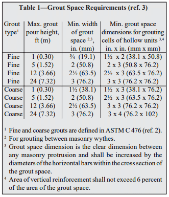
ASTM C 476 contains a proportion specification as well as a performance specification for masonry grout. The proportion specification specifies that coarse grout should have fine aggregate in the amount of 2 1/4 to 3 times the sum of the volume of the cementitious materials and coarse aggregate in the amount of 1 to 2 times the sum of the volume of the cementitious materials. These ASTM C 476 requirements are equivalent to s/a (sand/total aggregate) ratios of approximately 0.50 to 0.60 on an absolute volume basis. By comparison, most self-consolidating concrete mix designs have similar s/a ratios in the 0.50 to 0.60 range.

Cementitious Materials and Minus 100 (0.150 mm) Sieve Content and Composition

Grout is required to have a minimum compressive strength of 2,000 psi (14 MPa) after 28 days of curing (ref. 7). Building Code Requirements for Masonry Structures (ref. 10) sets an upper limit on the specified compressive strength of grout at 5,000 psi (34.5 MPa) at 28 days when using strength design of concrete masonry, although experience indicates that many conventional grouts develop strengths greater than this specification limit. Note that actual strengths are somewhat higher than the specified strength to assure compliance.

In the historical context of masonry materials, the term cementitious materials has commonly referred to the cement content (as well as lime in the case of masonry mortars) used in the manufacturing of masonry units, mortar or grout. In the production of SCG, however, the fraction of very fine aggregate particles present in the mix can have a significant influence on the plastic (and by association, the hardened) properties of SCG, and therefore needs to be considered in the batching of SCG. As such, the ‘powder’ content of an SCG mix, which includes both conventional cementitious materials as well as the very fine aggregate dust smaller than the 100 (0.150 mm) sieve, is monitored to ensure a stable SCG.

Adequate paste content is critical for making stable SCG mixes because the paste forms the matrix in which the particles are suspended. This paste is composed of cementitious materials (including the powder), water and entrained air, if any. The entire powder content of some mixes may contain auxiliary materials including pozzolanic and hydraulic materials, as well as ground limestone and inert fillers. These additions can improve and maintain cohesion and segregation resistance of the mix while lowering the overall cost and helping to control the ultimate strength of the mix.

Although not widely used in the U.S., ground limestone and inert fillers can be very effective in SCG mixes as a means of keeping compressive strengths to the lower range. They should be considered if they are regionally available. Fly ash can also be an effective addition because its use can help enhance the filling ability and slump flow of the mix while providing increased cohesion and reduced sensitivity to changes in water content.

Research has shown that slump flow values are increased when the fly ash replacement rates are between 20 and 40% of portland cement (ref. 11). If the goal is to control compressive strengths, Class F fly ash can be effective because it typically does not contribute as much to strength gain as Type C fly ash. GGBFS (Ground Granulated Blast Furnace Slag) has successfully been used in SCG mixes to replace some of the cement, but its high ultimate strength gain usually means that the compressive strengths of these mixes are usually similar (or sometimes higher) than straight cement mix designs. Research (ref. 12) has demonstrated that coarse SCG mixes could be made with total cementitious materials contents of 750 lb/yd3 (445 kg/m3), and possibly with 700 lb/yd3 (415 kg/m3). By comparison, a typical conventional coarse grout made to the proportion specifications of ASTM C 476 contains about 550 to 700 lb/yd3 (325 to 415 kg/m3) of cementitious materials.

Some limited testing in the CMHA research (ref. 12) demonstrated that fine SCG could be made with total cementitious materials contents in the range of 800 to 850 lb/yd3 (475 to 505 kg/m3). By comparison, a typical conventional fine grout made to the proportion specifications of ASTM C 476 will contain about 700 to 1,000 lb/yd3 (415 to 590 kg/m3) of cementitious materials.

Water Content

The term ‘natural slump’ describes the slump of the grout mix before the polycarboxylate is added. A common procedure for making self consolidating concrete is to set the initial water target to the amount needed to bring the mix to a ‘natural slump’ of 2 to 4 in. (51 to 102 mm). The polycarboxylate is then added to make the mix fluid enough to obtain the desired slump flow. This would also be an acceptable initial water target for making SCG, although CMHA research (ref. 12) indicated that some of the most successful batches of coarse and fine SCG made with the local materials used in the research had initial water targets that yielded a ‘natural slump’ of 6 to 9 in. (152 to 229 mm) before the polycarboxylate was added.

Admixtures

Admixtures are integral to the production of SCG. The primary admixture used to impart fluidity and stability to the SCG mix is a class of high-range water-reducing admixtures known as polycarboxylates (PC). These long-chain polymers are synthesized to help keep the cement grains dispersed while adding some cohesiveness and stability to the SCG mix.

Another class of admixtures often used to make SCG in conjunction with the PC is the Viscosity-Modifying Admixtures (VMA). VMAs help adjust viscosity and can improve the cohesiveness and stability of the mix while allowing it to flow without segregation. Not all PC and VMA products have the same properties. Some PCs impart substantial amounts of stability and cohesiveness to the mix and are recommended to be used without VMA, while others benefit from the addition of VMA.

In the past (before polycarboxylates), there have been indications that in some situations superplasticizers in grout for masonry structures have not performed well because they exhibited a short pot life, meaning the mix quickly lost fluidity and rapid stiffing would follow. Absorption of mix water into the surrounding masonry also negatively impacted the flow. In high-lift grouting (placing grout into grout columns as high as 24 ft (7.3 m)), enough water could be lost to cause the grout to stiffen and bridge before reaching the bottom of the grout column. With the advent of newer high-range water reducers such as polycarboxylates, however, this problem is no longer evident (ref. 13).

Note that proportioning of SCG is not permitted in the field (ref. 5). However, final adjustment of the mix, in accordance with the SCG manufacturer’s recommendations, utilizing water or the same admixture used in the mix is permitted.

SCG PLACEMENT

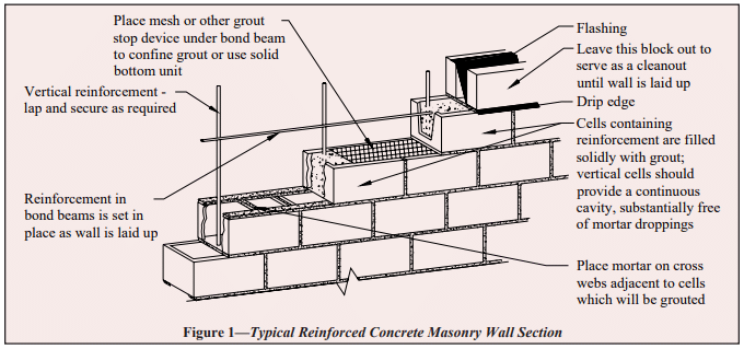
Self-consolidating grout is pumped or placed into spaces to be grouted using the same procedures as for conventional grout. Research has shown that with SCG there is no need to first remove mortar fins and protrusions exceeding 1/2 in. (13 mm), as is required for conventionally grouted masonry (refs. 3, 4), since SCG is fluid enough to flow around these small obstructions (ref. 13). However, it is important to note that Specification for Masonry Structures currently requires the removal of mortar fins and protrusions exceeding 1/2 in. (13 mm) for both conventional grout and SCG (ref. 5). Note that because SCG is so fluid, it will flow through gaps wider than about 3/8 in.

(10 mm). To contain the grout, therefore, it is recommended to mortar the masonry unit cross webs of cells containing grout in partially grouted construction.

In bond beams, SCG will be adequately contained using conventional grout-stop materials, such as plastic mesh. When filling intermediate bond beams using high-lift grouting, place the grout-stop material in the bed joints both above and below the bond beam to prevent the SCG from rising above the bond beam location.

Once the SCG is placed, consolidation and reconsolidation is not necessary with either coarse or fine SCG.

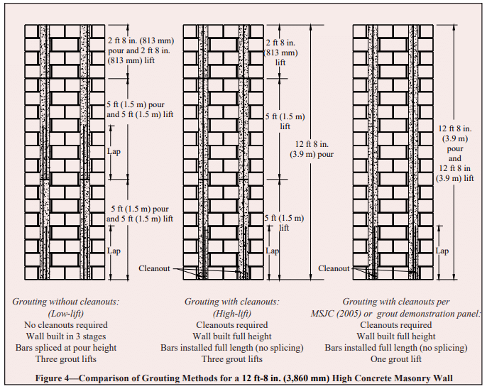
Documented successful lifts of 12 ft 8 in. (3.9 m) have been achieved by filling the grout columns of 8-in. (203-mm) concrete masonry walls in a single lift in less than a minute using a concrete pump (ref. 13). Other undocumented placements have placed SCG in a single 24-ft (7.3-m) lift. Twenty-four feet (7.3 mm) is the maximum pour height currently permitted by Building Code Requirements for Masonry Structures and Specification for Masonry Structures (refs. 10, 5). Note also that for SCG, grout lift height can equal the grout pour height.

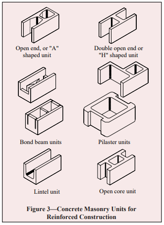
Blowouts have not been shown to be a problem for conventional masonry units in this research nor in field experience. However, specialty units with reduced or removed webs, such as “H-block” or large pilaster or column units, may require reduced lift heights.

No special curing procedures are required when using SCG. When appropriate, standard hot and cold weather construction provisions should be followed, as for other masonry projects. See All-Weather Concrete Masonry Construction, TEK 03-01C (ref. 14), for more detailed information.

SCG QUALITY ASSURANCE AND QUALITY CONTROL

Specification for Masonry Structures (ref. 5) requires SCG to:

  • meet the material requirements of ASTM C 476,
  • attain the specified compressive strength or 2,000 psi (13.79 MPa), whichever is greater, at 28 days when tested in accordance with ASTM C 1019 (ref. 15),
  • have a slump flow of 24 to 30 in. (610 to 762 mm) as determined by ASTM C 1611 (ref. 16), and
  • have a Visual Stability Index (VSI) less than or equal to 1 as determined in accordance with ASTM C 1611, Appendix X.1.

The ASTM C 476 material requirements are described in Grout for Concrete Masonry, TEK 09-04A (ref. 17). Other quality assurance and quality control provisions related to SCG are described below.

Some methods commonly used for self-consolidating concrete to evaluate passing ability, like the L-Box or J-Ring, are not normally used with SCG because experience indicates that the 3/8 in. (9.5 mm) maximum aggregate size used in SCG has adequate passing ability in masonry grouting applications.

Compressive Strength Testing of SCG Mixes

The current edition of ASTM C 1019, Standard Test Method for Sampling and Testing Grout (ref. 15), addresses the testing of SCG. The procedure for testing SCG is very similar to that for conventional grout, except that SCG is placed in the mold in one lift instead of two and SCG does not need to be rodded.

Slump Flow

The slump flow test method defined in ASTM C 1611/C 1611M, Standard Test Method for Slump Flow of Self-Consolidating Concrete (ref. 16) is used to monitor the consistency of fresh, unhardened SCG and its unconfined flow potential. It is particularly useful to assess the batch-to-batch consistency of SCG supplied over time.

Because of the fluid nature of SCG, traditional measures of consistency, such as the ASTM C 143 (ref. 18) slump test, are not applicable to SCG. The slump flow test is an adaptation of the ASTM C 143 slump cone test. In the slump flow test, SCG is loaded into an inverted slump cone in a single lift without consolidation. The cone is removed and the diameter of the grout slump flow is measured (see Figure 1).

Visual Stability Index (VSI)

VSI, also defined in ASTM C 1611, is performed after the slump flow test to provide a qualitative assessment of the SCG’s stability. The SCG patty resulting from the slump flow test is examined for aggregate segregation, bleeding and evidence of a mortar halo (a cement paste or mortar ring that has clearly separated from the coarse aggregate, around the outside circumference of the SCG patty). The SCG mix is then assigned a VSI, from 0 (highly stable) to 3 (highly unstable).

Although not required by Specification for Masonry Structures, T20 (T50) records the time it takes, during the slump flow test, for the outer edge of the SCG patty to reach a diameter of 20 in. (508 mm) from the time the mold is first raised. It is an optional test for self consolidating concrete, and is similarly applicable to SCG to provide a relative measure of the unconfined flow rate and an indication of the relative viscosity of the SCG. While the actual target value for T20 (T50) can vary for different SCG mixes, it has value in verifying the consistency between SCG batches delivered to the job site.

Self-Healing Ability ‘S’ Test

The ‘S’ test can also be used to help determine the stability of an SCG mix. While this is not a standardized test method, it is adapted from a simple test that is done by some practitioners in the field. There is a common version and a modified version, which gives an indication of the relative segregation resistance of the SCG when subjected to local vibration.

The common self-healing (non-disturbed) test is performed after the slump flow, T20 (T50) and VSI have been recorded. A 10- to 12-in. (254- to 305-mm) ‘S’ is drawn in the SCG patty with a finger, making sure to scrape off the SCG all the way down to the board. The patty is observed to see if the ‘S’ will self-heal. In cases where the self healing is excellent, the SCG flows back together and there is little or no evidence of the ‘S’ remaining. In cases where the self-healing is poor, the SCG does not flow back together and the ‘S’ remains very visible with severe aggregate, paste or water segregation.

Due to observations during the CMHA research (ref. 12), a self healing (after agitate) test was created. After completing the common self-healing test, the SCG patty is vibrated and a second test, designated self-healing (after agitate), is performed. To vibrate the mix, the side of the slump flow baseplate is lightly kicked or tapped six times with a foot (three on one side followed by three on an orthogonal [right-angle] side). The ‘S’ test is then repeated and the mix is rated again.

Suitability of Segregation Tests

In the CMHA research (ref. 12); several mixes were used to determine the suitability of self-consolidating concrete segregation tests on the SCG mixes. Testing was performed to evaluate both the Column Technique for Static Segregation (ASTM C 1610) (ref. 19) and the European Sieve Segregation Test (ref. 20). It was found that these tests were not able to distinguish unstable SCG mixes from stable mixes. It is not clear if this was a function of the particular raw materials used or a general characteristic of coarse SCG mixes. The selfhealing (after agitation) test described above was found to be a much better indicator of stable and unstable mixes for SCG.

REFERENCES

  1. Specification for Masonry Structures, ACI 530.1-02/ASCE
    6-02/TMS 602-02. Reported by the Masonry Standards
    Joint Committee, 2002.
  2. Specification for Masonry Structures, ACI 530.1-05/ASCE
    6-05/TMS 602-05. Reported by the Masonry Standards
    Joint Committee, 2005.
  3. International Building Code 2003. International Code
    Council, 2003.
  4. International Building Code 2006. International Code
    Council, 2006.
  5. Specification for Masonry Structures, ACI 530.1-08/ASCE
    6-08/TMS 602-08. Reported by the Masonry Standards
    Joint Committee, 2008.
  6. Standard Specification for Aggregates for Masonry Grout,
    ASTM C 404-07. ASTM International, Inc., 2007.
  7. Standard Specification for Grout for Masonry, ASTM C
    476-07. ASTM International, Inc., 2007.
  8. Standard Specification for Concrete Aggregates, ASTM C
    33-03. ASTM International, Inc., 2003.
  9. Standard Specification for Aggregate for Masonry Mortar,
    ASTM C 144-04. ASTM International, Inc., 2004.
  10. Building Code Requirements for Masonry Structures, ACI
    530-08/ASCE 5-08/TMS 402-08. Reported by the Masonry
    Standards Joint Committee, 2008.
  11. Studies of Self-Compacting High Performance Concrete
    with High Volume Mineral Additives. Fang, W.;Jianxiong,
    C.; Changhui, Y., Proceedings of the First International
    RILEM Symposium on Self-Compacting Concrete, 1999,
    p. 569-578.
  12. Self-Consolidating Grout Investigation: Making and
    Testing Prototype SCG Mix Designs – Report of Phase
    II Research, MR31. Concrete Masonry & Hardscapes
    Association, 2006.
  13. Self-Consolidating Grout Investigation: Compressive
    Strength, Shear Bond, Consolidation and Flow – Report
    of Phase I Research, MR29. Concrete Masonry &
    Hardscapes Association, 2006.
  14. All-Weather Concrete Masonry Construction, TEK 03-01C,
    Concrete Masonry & Hardscapes Association, 2002.
  15. Standard Test Method for Sampling and Testing Grout,
    ASTM C 1019-07. ASTM International, Inc., 2007.
  16. Standard Test Method for Slump Flow of SelfConsolidating Concrete, ASTM C 1611/C 1611M-05.
    ASTM International, Inc., 2005.
  17. Grout for Concrete Masonry, TEK 09-04A, Concrete
    Masonry & Hardscapes Association, 2005.
  18. Standard Test Method for Slump of Hydraulic-Cement
    Concrete, ASTM C 143-05a. ASTM International, Inc.,
    2005.
  19. Standard Test Method for Static Segregation of SelfConsolidating Concrete Using Column Technique, ASTM
    C 1610/C 1610M-06. ASTM International, Inc., 2006.
  20. The European Guidelines for Self-Compacting Concrete:
    Specification, Production and Use. Self Compacting
    Concrete European Project Group, 2005.

Construction of Reinforced Concrete Masonry Diaphragm Walls

INTRODUCTION

Diaphragm walls are composed of two wythes of masonry with a large cavity or void. The wythes are bonded together with masonry ribs or crosswalls in such a way that, structurally, the wythes function compositely—as though the entire thickness is effectively solid.

Figure 1 shows a stone-clad university building with reinforced concrete masonry diaphragm walls, used to recreate the campus’ Gothic architecture. The use of reinforced diaphragm walls allowed support of the tall sidewalls and gable ends.

Figure 2 shows a cross-section of a typical diaphragm wall. The reinforced wythes can be fully or partially grouted. The exterior face can be constructed with a weathering face, like a conventional single wythe wall, or finished with a veneer. The voids can be used for placement of utilities and/or insulation.

This TEK discusses construction considerations for diaphragm walls: TEK 14-24, Design of Reinforced Concrete Masonry Diaphragm Walls, (ref. 1) covers the structural design.

CONSTRUCTION ADVANTAGES

Reinforced diaphragm walls present several construction benefits. These include:

  1. As shown in Figure 1, thick walls can be created efficiently using standard units bonded together. Thicker walls can be used to create taller walls.
  2. The wall can have exposed finished surfaces both inside and out. In addition, those finishes can be different because they are created by two different masonry wythes and can, therefore, feature different unit types/sizes/colors.
  3. The wall construction proceeds very much as conventional single wythe or cavity wall construction.
  4. The exterior wythe can be constructed with a veneer.
  5. The large interior voids allow for easy placement of utilities and/or insulation.

KEY CONSTRUCTION FEATURES

Construction Sequence

The construction sequence for diaphragm walls can vary based upon how the ribs are interconnected with the two wythes. Building Code Requirements for Masonry Structures (ref. 2), referred to as TMS 402, Section 5.1.1.2.5 provides three methods for connecting intersecting walls to allow shear transfer:

  1. At least fifty percent of the masonry units at the interface must interlock. This means the ribs could be constructed in running bond with every other course interlocking with the wythes. Thus, the wythes and the ribs would be constructed concurrently.
  2. Walls must be anchored by steel connectors grouted into the wall and meeting the following requirements: (a) Minimum size: 1/4 in. x 1-1/2 in. x 28 in. (6.4 x 38.1 x 711 mm) including 2-in. (50.8-mm) long, 90-degree bend at each end to form a U or Z-shape. (b) Maximum spacing: 48 in. (1,219 mm). Thus, it is possible to build the ribs separately from the wythes, which provides significant flexibility in construction.
  3. Intersecting reinforced bond beams must be provided at a maximum spacing of 48 in. (1,219 mm) on center. The area of reinforcement in each bond beam must be not less than 0.1 in.2 per ft (211 mm2/m) multiplied by the vertical spacing of the bond beams in feet (meters). Reinforcement must be developed on each side of the intersection.

Again, this provides flexibility in sequencing the wall construction. However, the grouting must be done simultaneously with the wythe construction.

Masonry Bond

TMS 402 Section 5.1.1.2.1 requires that the masonry at intersecting walls be laid in running bond for composite action between wythes to be effective. This requirement controls the entire construction of a diaphragm wall and mandates running bond for both the wythes and the ribs.

Reinforcement

Vertical reinforcement is typically placed in the cells of the wythes as is done in single-wythe construction. Posttensioning can be placed either in the cells of the wythes or within the void itself. If placed within the void and laterally restrained tendons are specified, tendon restraints must be fabricated. TEK 03-14, Post-Tensioned Concrete Masonry Wall Construction (ref. 3) provides a more detailed overview. Depending on the project’s seismic and/or loading requirements, horizontal reinforcement can be placed in either grouted bond beams or in the bed joints of the wythes and ribs. Horizontal bond beams are beneficial in that they can also serve as the interlock between the ribs and wythes, as well as shear reinforcement for the ribs.

Ribs (Crosswalls)

The structural design will determine whether or not the ribs require vertical reinforcement. The interlock with the wythes transfers shear forces across the intersections, and the vertical reinforcement in the wythes acts as the total wall reinforcement.

Wall Grouting

The requirement for full or partial wall grouting is a design decision. Any cells or bond beams with reinforcement must be grouted. The need for additional grouting is determined based on the design requirements. Both low-lift and high-lift grouting techniques are suitable to diaphragm walls. See TEK 03-02A, Grouting Concrete Masonry Walls, (ref. 4) for more detailed information.

Water Management

Strategies for water penetration resistance of conventional masonry walls depend on whether the wall is singlewythe or a cavity wall. Water penetration resistance for the exterior wythe of a diaphragm wall follows the strategies employed for single wythe construction. If the exterior wythe has a veneer and cavity, it is flashed and weeped the same way as a single wythe masonry cavity wall. With no veneer and cavity, the exterior wythe of a diaphragm wall is flashed and weeped the same way as a similarly constructed partially grouted single wythe wall. Flashing and weeps are not necessary if the exterior wythe is solid grouted.

Figure 3 shows a typical wall base detail for a diaphragm wall with an exterior veneer and cavity. The cavity between the exterior diaphragm wythe may contain insulation and an air/moisture barrier, as required. The veneer is anchored to the exterior wythe of the diaphragm wall and is weeped and flashed. TEK 19-05A, Flashing Details for Concrete Masonry Walls, (ref. 6) provides additional details applicable to this construction.

Figure 4 shows a wall base detail applicable to an exterior diaphragm wythe without a cavity and veneer. TEK 19-02B, Design for Dry Single Wythe Concrete Masonry Walls, (ref. 7) provides additional details for single wythe construction.

Openings through diaphragm walls, roof/floor intersections, etc. are also flashed and weeped similar to conventional concrete masonry walls.

Top of the Wall

Diaphragm walls require closure at the top to transfer vertical loads and close off the void. Figure 5 shows one common detail for capping the walls. The cast-in-place capping slab at the top takes the place of what would normally be bond beams in single-wythe walls. For post tensioned walls, the top slab provides a convenient anchorage point for the tendons.

Utilities and Insulation

The voids offer several opportunities not common in masonry walls. They provide chases for duct work and utilities with minimal cutting of the units and allow for additional insulation if desired. Diaphragm walls can be insulated on the exterior, by using a veneer and insulated cavity, or by using an exterior insulation system. They can also be insulated on the interior, using furring, insulation and gypsum wallboard. When insulation is placed in the voids, however, the ribs produce a large thermal bridge, reducing the effectiveness of the insulation. 06-11A, Insulating Concrete Masonry Walls, (ref. 5) provides more detailed information.

Openings

Constructing openings in diaphragm walls is also very similar to single-wythe walls (see Figure 6). The entire void should be spanned/filled at the opening and the exterior wythe flashed above (as appropriate), as shown in Figure 4. Figure 6 Option 1 shows a reinforced concrete slab that has been designed as a header for the opening. Figure 6 Option 2 has lintels to support the wythes over the opening. The void at the headers and sills is infilled with a nonmasonry material, such as exterior gypsum sheathing. The jambs should be infilled with masonry wherever they don’t already align with the ribs. Note that Figure 6 does not show flashing that may be necessary.

Control Joints

Control joints are provided in concrete masonry walls to control cracking primarily from movement due to shrinkage and thermal effects. In diaphragm walls, the ribs will tend to restrict some of that movement, however, because there is currently no research to quantify these effects, current practice is to place control joints at intervals based upon CMU-TEC-009-23, Crack Control Strategies for Concrete Masonry Construction, (ref. 8). TEK 14-24 discusses these criteria and provides an example for determining control joint spacing for a diaphragm wall.

Although the inner wythe will generally be exposed principally to shrinkage with only minor thermal effects, it is common to place control joints in the same locations and to provide similar shrinkage reinforcement in both wythes.

Figure 7 shows two methods of creating control joints in a diaphragm wall. Option 1, with ribs on both sides of the control joint, does a better job keeping water out of the void than Option 2 because a failure of the sealant would allow water to penetrate between the ribs, rather than into the void itself. The control joints in both wythes should be sealed for water protection.

CMU-TEC-009-23 contains additional control joint constructions/details that can also be used on diaphragm walls, including fire-rated joints and control joints that allow shear transfer.

SUMMARY

Diaphragm walls provide several beneficial features and are applicable to a wide variety of projects. Constructing reinforced concrete masonry diaphragm walls uses methods and techniques commonly known to most masons. The added thickness of the wall provides some variations in the overall reinforcement and layout concepts but the techniques are typical for masonry.

REFERENCES

  1. Design of Reinforced Concrete Masonry Diaphragm Walls, TEK 14-24. Concrete Masonry & Hardscapes Association, 2014.
  2. Building Code Requirements for Masonry Structures, TMS 402-16, Reported by The Masonry Society 2016.
  3. Post-Tensioned Concrete Masonry Wall Construction, TEK 03-14. Concrete Masonry & Hardscapes Association, 2002.
  4. Grouting Concrete Masonry Walls, TEK 03-2A. Concrete Masonry & Hardscapes Association, 2005.
  5. Insulating Concrete Masonry Walls, TEK 06-11A. Concrete Masonry & Hardscapes Association, 2010.
  6. Flashing Details for Concrete Masonry Walls, TEK 19-05A.
    Concrete Masonry & Hardscapes Association, 2008.
  7. Design for Dry Single Wythe Concrete Masonry Walls, TEK 19-02B. Concrete Masonry & Hardscapes Association, 2012.
  8. Crack Control Strategies for Concrete Masonry Construction, CMU-TEC-009-23, Concrete Masonry & Hardscapes Association, 2023.

Grouting Concrete Masonry Walls

INTRODUCTION

Grouted concrete masonry construction offers design flexibility through the use of partially or fully grouted walls, whether plain or reinforced. The industry is experiencing fast-paced advances in grouting procedures and materials as building codes allow new opportunities to explore means and methods for constructing grouted masonry walls.

Grout is a mixture of: cementitious material (usually portland cement); aggregate; enough water to cause the mixture to flow readily and without segregation into cores or cavities in the masonry; and sometimes admixtures. Grout is used to give added strength to both reinforced and unreinforced concrete masonry walls by grouting either some or all of the cores. It is also used to fill bond beams and occasionally to fill the collar joint of a multi-wythe wall. Grout may also be added to increase the wall’s fire rating, acoustic effectiveness termite resistance, blast resistance, heat capacity or anchorage capabilities. Grout may also be used to stabilize screen walls and other landscape elements.

In reinforced masonry, grout bonds the masonry units and reinforcing steel so that they act together to resist imposed loads. In partially grouted walls, grout is placed only in wall spaces containing steel reinforcement. When all cores, with or without reinforcement, are grouted, the wall is considered solidly grouted. If vertical reinforcement is spaced close together and/or there are a significant number of bond beams within the wall, it may be faster and more economical to solidly grout the wall.

Specifications for grout, sampling and testing procedures, and information on admixtures are covered in CMHA TEK 09-04A, Grout for Concrete Masonry (ref. 1). This TEK covers methods for laying the units, placing steel reinforcement and grouting.

WALL CONSTRUCTION

Figure 1 shows the basic components of a typical reinforced concrete masonry wall. When walls will be grouted, concrete masonry units must be laid up so that vertical cores are aligned to form an unobstructed, continuous series of vertical spaces within the wall.

Head and bed joints must be filled with mortar for the full thickness of the face shell. If the wall will be partially grouted, those webs adjacent to the cores to be grouted are mortared to confine the grout flow. If the wall will be solidly grouted, the cross webs need not be mortared since the grout flows laterally, filling all spaces. In certain instances, full head joint mortaring should also be considered when solid grouting since it is unlikely that grout will fill the space between head joints that are only mortared the width of the face shell, i.e., when penetration resistance is a concern such as storm shelters and prison walls. In cases such as those, open end or open core units (see Figure 3) should be considered as there is no space between end webs with these types of units.

Care should be taken to prevent excess mortar from extruding into the grout space. Mortar that projects more than ½ in. (13 mm) into the grout space must be removed (ref. 3). This is because large protrusions can restrict the flow of grout, which will tend to bridge at these locations potentially causing incomplete filling of the grout space. To prevent bridging, grout slump is required to be between 8 and 11 in. (203 to 279 mm) (refs. 2, 3) at the time of placement. This slump may be adjusted under certain conditions such as hot or cold weather installation, low absorption units or other project specific conditions. Approval should be obtained before adjusting the slump outside the requirements. Using the grout demonstration panel option in Specification for Masonry Structures (ref. 3) is an excellent way to demonstrate the acceptability of an alternate grout slump. See the Grout Demonstration Panel section of this TEK for further information.

At the footing, mortar bedding under the first course of block to be grouted should permit grout to come into direct contact with the foundation or bearing surface. If foundation dowels are present, they should align with the cores of the masonry units. If a dowel interferes with the placement of the units, it may be bent a maximum of 1 in. (25 mm) horizontally for every 6 in. (152 mm) vertically (see Figure 2). When walls will be solidly grouted, saw cutting or chipping away a portion of the web to better accommodate the dowel may also be acceptable. If there is a substantial dowel alignment problem, the project engineer must be notified.

Vertical reinforcing steel may be placed before the blocks are laid, or after laying is completed. If reinforcement is placed prior to laying block, the use of open-end A or H- shaped units will allow the units to be easily placed around the reinforcing steel (see Figure 3). When reinforcement is placed after wall erection, reinforcing steel positioners or other adequate devices to hold the reinforcement in place are commonly used, but not required. However, it is required that both horizontal and vertical reinforcement be located within tolerances and secured to prevent displacement during grouting (ref. 3). Laps are made at the end of grout pours and any time the bar has to be spliced. The length of lap splices should be shown on the project drawings. On occasion there may be locations in the structure where splices are prohibited. Those locations are to be clearly marked on the drawing.

Reinforcement can be spliced by either contact or noncontact splices. Noncontact lap splices may be spaced as far apart as one-fifth the required length of the lap but not more than 8 in. (203 mm) per Building Code Requirements for Masonry Structures (ref. 4). This provision accommodates construction interference during installation as well as misplaced dowels. Splices are not required to be tied, however tying is often used as a means to hold bars in place.

As the wall is constructed, horizontal reinforcement can be placed in bond beam or lintel units. If the wall will not be solidly grouted, the grout may be confined within the desired grout area either by using solid bottom masonry bond beam units or by placing plastic or metal screening, expanded metal lath or other approved material in the horizontal bed joint before laying the mortar and units being used to construct the bond beam. Roofing felt or materials that break the bond between the masonry units and mortar should not be used for grout stops.

CONCRETE MASONRY UNITS AND REINFORCING BARS

Standard two-core concrete masonry units can be effectively reinforced when lap splices are not long, since the mason must lift the units over any vertical reinforcing bars that extend above the previously installed masonry. The concrete masonry units illustrated in Figure 3 are examples of shapes that have been developed specifically to accommodate reinforcement. Open-ended units allow the units to be placed around reinforcing bars. This eliminates the need to thread units over the top of the reinforcing bar. Horizontal reinforcement in concrete masonry walls can be accommodated either by saw-cutting webs out of a standard unit or by using bond beam units. Bond beam units are manufactured with either reduced webs or with “knock-out” webs, which are removed prior to placement in the wall. Pilaster and column units are used to accommodate a wall- column or wall-pilaster interface, allowing space for vertical reinforcement and ties, if necessary, in the hollow center.

Concrete masonry units should meet applicable ASTM standards and should typically be stored on pallets to prevent excessive dirt and water from contaminating the units. The units may also need to be covered to protect them from rain and snow.

The primary structural reinforcement used in concrete masonry is deformed steel bars. Reinforcing bars must be of the specified diameter, type and grade to assure compliance with the contract documents. See Steel Reinforcement for Concrete Masonry, TEK 12-04D for more information (ref. 6). Shop drawings may be required before installation can begin.

Light rust, mill scale or a combination of both need not be removed from the reinforcement. Mud, oil, heavy rust and other materials which adversely affect bond must be removed however. The dimensions and weights (including heights of deformations) of a cleaned bar cannot be less than those required by the ASTM specification.

GROUT PLACEMENT

To understand grout placement, the difference between a grout lift and a grout pour needs to be understood. A lift is the amount of grout placed in a single continuous operation. A pour is the entire height of masonry to be grouted prior to the construction of additional masonry. A pour may be composed of one lift or a number of successively placed grout lifts, as illustrated in Figure 4.

Historically, only two grout placement procedures have been in general use: (l) where the wall is constructed to pour heights up to 5 ft (1,520 mm) without cleanouts—generally termed “low lift grouting;” and (2) where the wall is constructed to a maximum pour height of 24 ft (7,320 mm) with required cleanouts and lifts are placed in increments of 5 ft (1,520 mm)—generally termed “high lift grouting.” With the advent of the 2002 Specification for Masonry Structures (ref. 5), a third option became available – grout demonstration panels. The 2005 Specification for Masonry Structures (ref. 3) offers an additional option: to increase the grout lift height to 12 ft-8 in. (3,860 mm) under the following conditions:

  1. the masonry has cured for at least 4 hours,
  2. grout slump is maintained between 10 and 11 in. (245 and 279 mm), and
  3. no intermediate reinforced bond beams are placed between the top and the bottom of the pour height.

Through the use of a grout demonstration panel, lift heights in excess of the 12 ft-8 in. (3,860 mm) limitation may be permitted if the results of the demonstration show that the completed grout installation is not adversely affected. Written approval is also required.

These advances permit more efficient installation and construction options for grouted concrete masonry walls (see Figure 4).

Grouting Without Cleanouts—”Low-Lift Grouting”

Grout installation without cleanouts is sometimes called low-lift grouting. While the term is not found in codes or standards, it is common industry language to describe the process of constructing walls in shorter segments, without the requirements for cleanout openings, special concrete block shapes or equipment. The wall is built to scaffold height or to a bond beam course, to a maximum of 5 ft (1,520 mm). Steel reinforcing bars and other embedded items are then placed in the designated locations and the cells are grouted. Although not a code requirement, it is considered good practice (for all lifts except the final) to stop the level of the grout being placed approximately 1 in. (25 mm) below the top bed joint to help provide some mechanical keying action and water penetration resistance. Further, this is needed only when a cold joint is formed between the lifts and only in areas that will be receiving additional grout. Steel reinforcement should project above the top of the pour for sufficient height to provide for the minimum required lap splice, except at the top of the finished wall.

Grout is to be placed within 1 ½ hours from the initial introduction of water and prior to initial set (ref. 3). Care should be taken to minimize grout splatter on reinforcement, on finished masonry unit faces or into cores not immediately being grouted. Small amounts of grout can be placed by hand with buckets. Larger quantities should be placed by grout pumps, grout buckets equipped with chutes or other mechanical means designed to move large volumes of grout without segregation.

Grout must be consolidated either by vibration or puddling immediately after placement to help ensure complete filling of the grout space. Puddling is allowed for grout pours of 12 in. (305 mm) or less. For higher pour heights, mechanical vibration is required and reconsolidation is also required. See the section titled Consolidation and Reconsolidation in this TEK.

Grouting With Cleanouts—”High-Lift Grouting”

Many times it is advantageous to build the masonry wall to full height before grouting rather than building it in 5 ft (1,520 mm) increments as described above. With the installation of cleanouts this can be done. Typically called high-lift grouting within the industry, grouting with cleanouts permits the wall to be laid up to story height or to the maximum pour height shown in Table 1 prior to the installation of reinforcement and grout. (Note that in Table 1, the maximum area of vertical reinforcement does not include the area at lap splices.) High lift grouting offers certain advantages, especially on larger projects. One advantage is that a larger volume of grout can be placed at one time, thereby increasing the overall speed of construction. A second advantage is that high-lift grouting can permit constructing masonry to the full story height before placing vertical reinforcement and grout. Less reinforcement is used for splices and the location of the reinforcement can be easily checked by the inspector prior to grouting. Bracing may be required during construction. See Bracing Concrete Masonry Walls During Construction, TEK 03-04C (ref. 7) for further information.

Cleanout openings must be made in the face shells of the bottom course of units at the location of the grout pour. The openings must be large enough to allow debris to be removed from the space to be grouted. For example, Specification for Masonry Structures (ref. 3) requires a minimum opening dimension of 3 in. (76 mm).

Cleanouts must be located at the bottom of all cores containing dowels or vertical reinforcement and at a maximum of 32 in. (813 mm) on center (horizontal measurement) for solidly grouted walls. Face shells are removed either by cutting or use of special scored units which permit easy removal of part of the face shell for cleanout openings (see Figure 5). When the cleanout opening is to be exposed in the finished wall, it may be desirable to remove the entire face shell of the unit, so that it may be replaced in whole to better conceal the opening. At flashing where reduced thickness units are used as shown in Figure 1, the exterior unit can be left out until after the masonry wall is laid up. Then after cleaning the cell, the unit is mortared in which allowed enough time to gain enough strength to prevent blowout prior to placing the grout.

Proper preparation of the grout space before grouting is very important. After laying masonry units, mortar droppings and projections larger than ½ in. (13 mm) must be removed from the masonry walls, reinforcement and foundation or bearing surface. Debris may be removed using an air hose or by sweeping out through the cleanouts.

The grout spaces should be checked by the inspector for cleanliness and reinforcement position before the cleanouts are closed. Cleanout openings may be sealed by mortaring the original face shell or section of face shell, or by blocking the openings to allow grouting to the finish plane of the wall. Face shell plugs should be adequately braced to resist fluid grout pressure.

It may be advisable to delay grouting until the mortar has been allowed to cure, in order to prevent horizontal movement (blowout) of the wall during grouting. When using the increased grout lift height provided for in Article 3.5 D of Specification for Masonry Structures (ref 3), the masonry is required to cure for a minimum of 4 hours prior to grouting for this reason.

Consolidation and Reconsolidation

An important factor mentioned in both grouting procedures is consolidation. Consolidation eliminates voids, helping to ensure complete grout fill and good bond in the masonry system.

As the water from the grout mixture is absorbed into the masonry, small voids may form and the grout column may settle. Reconsolidation acts to remove these small voids and should generally be done between 3 and 10 minutes after grout placement. The timing depends on the water absorption rate, which varies with such factors as temperature, absorptive properties of the masonry units and the presence of water repellent admixtures in the units. It is important to reconsolidate after the initial absorption has taken place and before the grout loses its plasticity. If conditions permit and grout pours are so timed, consolidation of a lift and reconsolidation of the lift below may be done at the same time by extending the vibrator through the top lift and into the one below. The top lift is reconsolidated after the required waiting period and then filled with grout to replace any void left by settlement.

A mechanical vibrator is normally used for consolidation and reconsolidation—generally low velocity with a ¾ in. to 1 in. (19 to 25 mm) head. This “pencil head” vibrator is activated for a few seconds in each grouted cell. Although not addressed by the code, recent research (ref. 8) has demonstrated adequate consolidation by vibrating the top 8 ft (2,440 mm) of a grout lift, relying on head pressure to consolidate the grout below. The vibrator should be withdrawn slowly enough while on to allow the grout to close up the space that was occupied by the vibrator. When double open- end units are used, one cell is considered to be formed by the two open ends placed together. When grouting between wythes, the vibrator is placed at points spaced 12 to 16 in. (305 to 406 mm) apart. Excess vibration may blow out the face shells or may separate wythes when grouting between wythes and can also cause grout segregation.

GROUT DEMONSTRATION PANEL

Specification for Masonry Structures (ref. 3) contains a provision for “alternate grout placement” procedures when means and methods other than those prescribed in the document are proposed. The most common of these include increases in lift height, reduced or increased grout slumps, minimization of reconsolidation, puddling and innovative consolidation techniques. Grout demonstration panels have been used to allow placement of a significant amount of a relatively new product called self-consolidating grout to be used in many parts of the country with outstanding results. 

Research has demonstrated comparable or superior performance when compared with consolidated and reconsolidated conventional grout in regard to reduction of voids, compressive strength and bond to masonry face shells. Construction and approval of a grout demonstration panel using the proposed grouting procedures, construction techniques and grout space geometry is required. With the advent of self-consolidating grouts and other innovative consolidation techniques, this provision of the Specification has been very useful in demonstrating the effectiveness of alternate grouting procedures to the architect/engineer and building official.

COLD WEATHER PROTECTION

Protection is required when the minimum daily temperature during construction of grouted masonry is o o expected to fall below 40 F (4.4 C). Grouted masonry requires special consideration because of the higher water content and potential disruptive expansion that can occur if that water freezes. Therefore, grouted masonry requires protection for longer periods than ungrouted masonry to allow the water to dissipate. For more detailed information on cold, hot, and wet weather protection, see All-Weather Concrete Masonry Construction, TEK 03-01C (ref. 9).

REFERENCES

  1. Grout for Concrete Masonry, TEK 09-04A. Concrete Masonry & Hardscapes Association, 2005.
  2. Standard Specification for Grout for Masonry, ASTM C 476-02, ASTM International, 2005.
  3. Specification for Masonry Structures, ACI 530.1-05/ ASCE 6-05/TMS 602-05. Reported by the Masonry Standards Joint Committee, 2005.
  4. Building Code Requirements for Masonry Structures, ACI 530-05/ASCE 5-05/TMS 402-05. Reported by the Masonry Standards Joint Committee, 2005.
  5. Specification for Masonry Structures, ACI 530.1-02/ ASCE 6-02/TMS 602-02. Reported by the Masonry Standards Joint Committee, 2002.