The current trend of urban renewal and infill has sparked a high volume of new low-rise masonry residences. These structures come in many forms, but quite often they employ the use of load-bearing concrete masonry walls supporting a wood floor system. These new buildings are largely derivative of the historic load bearing masonry “brownstone” or “three flat” structures of old. This guide is intended to assist contractors and architects to give this building type a modern approach to detailing.
FLOOR SYSTEM CONNECTIONS
When designing low-rise loadbearing structures, the connection detail between the floor system and the wall system is critical for achieving a watertight structure. Much of this TEK will deal with which strategy should be utilized in connecting a wood floor system to a masonry load-bearing wall. Connection methods covered are joist hangers, beam pockets and ledger beam details. Other floor systems are used in low-rise construction that are not addressed here – see 05-07A for further information (ref. 2).
BRICK AND BLOCK COMPOSITE WALL DETAILS
Quite often, the front facade of these structures is composed of brick to give the building a more residential, more human scale. One way to construct a brick and block wall is to separate the two wythes with an airspace, creating a cavity wall. Another is to use a composite wall design. The composite wall consists of an exterior wythe of brick directly mortared or grouted and tied to an inner wythe of CMU. The collar joint between the two wythes should be 100% solid as it is the only defense against water penetration. Minimum tie requirements are one tie per 22/3ft2 of wall area for W1.7 (MW11)(9 gauge) wire or one tie per 41/2ft2 of wall area using W2.8 (MW19)(3/16 in.)wire (ref. 2). A W1.7 (MW11)(9 gauge) joint reinforcement @16 in. (406 mm) on center would meet this requirement and is often used. Details covered for this system are base flashing, window head and window sill details.
EXTERIOR CONCRETE MASONRY
The use of water repellent admixtures in concrete masonry and mortars can greatly reduce the amount of water entering the masonry. In addition, they inhibit any water that penetrates the face from wicking to the back of the wall.
Proper selection and application of integral water repellents and surface treatments can greatly enhance the water resistive properties of masonry, but they should not be considered as substitutes for good fundamental design including flashing details and crack control measures. See TEKs 19-01, 19-02A, and 19-04A (refs. 6, 3, & 5) for more information on water resistant concrete masonry construction.
Because a 4 in. (102 mm) concrete masonry veneer will shrink over time, a 4 in. (102 mm) hot-dipped galvanized ladder type joint reinforcement should be placed in bed joints spaced 16 in. (406 mm) vertically.
Compared to type N or O, type S mortar tends to be less workable in the field and should only be specified when dictated by structural requirements. Sills, copings and chimney caps of solid masonry units, reinforced concrete, stone, or corrosion resistant metal should be used. Copings, sills and chimney caps should project beyond the face of the wall at least 1 in. (25 mm) and should have functional flashing and weep holes.
In addition, all sills, copings and chimney caps should have a minimum slope of 1:4, be mechanically anchored to the wall, and should have properly sized, sealed, and located movement joints when necessary.
Flashing should be installed at locations shown on the plans and in strict accordance with the details and industry standard flashing procedures. Functional, unpunctured flashing and weep holes are to be used at the base of wall above grade, above openings, at shelf angles, lintels, wall-roofing intersections, chimneys, bay windows, and below sills and copings. The flashing should be extended past the face of the wall. The flashing should have end dams at discontinuous ends, and properly sealed splices at laps.
JOIST HANGER DETAILS
The use of a joist hanger system can greatly simplify the bearing detail. The floor system does not interrupt the continuity of the bearing wall. Installation is quicker and easier resulting in a more economical installation.
BEAM POCKET DETAILS
The traditional beam pocket detail still can be effective. Stepped flashing above the bearing line is critical to the performance of this system. Without the flashing, any water present in the wall has an unobstructed path inside the building and has the potential to deteriorate the floor structure.
LEDGER BEAM DETAILS
The use of a ledger beam which is bolted to a bond beam is also a good option for this bearing condition. Through wall flashing is still required to maintain a watertight wall. Any water that penetrates the block with run down the inner cores of the block until it hits the flashing. The flashing and weep holes will allow the water to exit without damaging the structure.
PARAPETS AND WINDOW SILLS
Below are details for a parapet condition and a window sill condition. The parapet is reinforced with No. 4 bars at 48 in. (No.13M @1219 mm) on center or as required for wind resistance. If a metal cap is used, it should extend down the face of the wall at least 3 in. (76 mm) with continuous sealant at the joint on both sides of the wall. The sill detail shows the arrangement of flashing, end dam, weep holes and drip edge and how they all form a watertight
WINDOW HEAD DETAILS
These two window head details show the relationship between the steel lintel, drip edge, flashing, end dams, and weep holes. The first option shows the use of a concrete masonry lintel which is grouted solid and reinforced. The second detail shows two steel lintels used for spanning the opening.
CONTROL JOINT DETAILS
Control joints simply are weakened planes placed at approximately 20 ft. (6 m) on center in concrete masonry walls and at changes in wall elevation/thickness. Notice that the joint reinforcement is discontinuous at the joint. Cores are shown grouted adjacent to the joints as well to ensure structural stability in taller walls and/or high load situations.
COMPOSITE WALL BASE FLASHING DETAILS
Figure 14 shows a stair-stepped flashing detail with the exposed drip edge and weep holes. Figure 15 shows a straight through wall flashing detail. The flashing must be set in mastic on top of the concrete foundation, or the flashing must be self adhesive. The flashing should be turned up on the inner side of the wall to direct water to the outside of the wall.
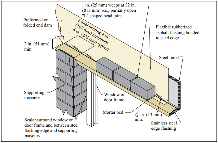
COMPOSITE WALL WINDOW DETAILS
Here steel lintels back-to-back create the above window span. Stepped flashing turned up on the inside, and folded to form an end dam protects the head condition from moisture. The sill detail also uses flashing, end dams and weep holes to keep moisture out of the wall. The use of a precast concrete or stone sill is highly suggested over using brick rowlock sills.
CONCRETE MASONRY VENEER DETAILING
Figure 18 shows the detailing of a 4 in. (102 mm) concrete masonry veneer used in conjunction with a 8 in. (205 mm) CMU backup wall.
Three types of joint reinforcement are shown including tri-rod, tab and adjustable types. It is imperative that the veneer have a continuous wire embedded in every other course to control movement. With the tri-rod system, the joint reinforcement satisfies this requirement. With the other two systems, an additional ladder type joint reinforcement is used to provide this movement control for the veneer.
REFERENCES
Building Code Requirements for Masonry Structures, ACI 530-05/ASCE 6-05/TMS-402-05. Reported by the Masonry Standards Joint Committee, 2005.
Floor and Roof Connections to Concrete Masonry Walls, TEK 05-07A, Concrete Masonry & Hardscapes Association, 2001.
Design for Dry Single-Wythe Concrete Masonry Walls, TEK 19-02B, Concrete Masonry & Hardscapes Association, 2004.
Flashing Details for Concrete Masonry Walls, TEK 19-05A, Concrete Masonry & Hardscapes Association, 2004.
Flashing Strategies for Concrete Masonry Walls, TEK 19- 04A, Concrete Masonry & Hardscapes Association, 2003.
Water Repellents for Concrete Masonry Walls, TEK 19-01, Concrete Masonry & Hardscapes Association, 2002.
Building codes include requirements for minimum reinforcement development lengths and splice lengths, as well as requirements for standard hooks, to ensure the adequate transfer of stresses between the reinforcement and the masonry. This TEK presents these requirements, based on the provisions of both the 2012 and 2009 editions of the International Building Code (IBC) (refs. 1, 2). Masonry design in these codes is primarily based on Building Code Requirements for Masonry Structures (MSJC) (refs. 3, 4). Differences between the MSJC and IBC are noted in the text when they occur.
There are two main differences between the 2008 and 2011 editions of the MSJC that impact reinforcement development and splice lengths in the corresponding 2009 and 2012 editions of the IBC:
under 2011 MSJC allowable stress design, the allowable tensile stress, Fs, of Grade 60 steel was increased from 24,000 psi (166 MPa) to 32,000 psi (221 MPa), and
the 2011 MSJC includes new lap splice length provisions for when confinement reinforcement is used at lap splices.
TEK 12-04D (ref. 5) includes basic material requirements, corrosion protection and placement tolerances for reinforcement used in concrete masonry construction. In addition, prestressing steel is discussed in Post-Tensioned Concrete Masonry Wall Construction, TEK 03-14 (ref. 6).
SPLICES AND DEVELOPMENT LENGTH
Minimum development lengths are necessary to adequately transfer stresses between reinforcement and the grout or mortar in which it is embedded. Splicing of reinforcement serves a similar purpose: to adequately transfer stresses from one reinforcing bar to another.
Reinforcement can be developed by embedment length, hook, or mechanical anchoring device. The development of the reinforcing bars relies on mechanical interlock of the bar deformations, hook, and/or anchor along with sufficient masonry cover to prevent splitting of the masonry. Reinforcing bars may be spliced by lapping the reinforcement, by proprietary mechanical splices or by welding.
The required length of lap or development is determined according to the design procedure used (allowable stress design or strength design). In addition, these detailing requirements have been frequently revised in recent years. As a result, the minimum lap and development lengths can vary considerably from one code to the next as well as from one design method to another.
The following sections present the requirements for both the 2009 IBC and 2012 IBC for both allowable stress and strength design.
2009 IBC SPLICE & DEVELOPMENT REQUIREMENTS
2009 IBC Allowable Stress Design
Development Length & Lap Splicing
While the 2008 MSJC includes an equation to determine development and lap splice lengths, the 2009 IBC modifies the MSJC lap splice length. In accordance with the 2009 IBC, the minimum required lap length for spliced reinforcing bars is determined using Equation 1 (see Table 1).
but not less than 12 in. (305 mm) or 40db, whichever b is greater
Further, in regions of flexure where the design tensile stresses in the reinforcement, fs, exceed 80% of the allowable steel tensile stress, Fs, the IBC requires that the required length of lap determined by Equation 1 must be increased by 50%. Alternatively, equivalent means of stress transfer to accomplish the same 50% increase is permitted. Where epoxy coated bars are used, lap length is also required to be increased by 50% but does not apply to the 12 in. (305 mm) minimum.
Development length requirements for allowable stress design are determined in accordance with Equation 3 except that there is no maximum length limit of 72db.
When noncontact lap splices are used, the bars must be spaced no farther apart than one-fifth the required length of lap nor more than 8 in. (203 mm).
When using the allowable stress design method, development of wires in tension is determined using Equation 2 (see Table 2). The development length of epoxy-coated wires is increased 50% above the value determined using Equation 2 but does not apply to the 6 in. (152 mm) minimum.
Table 2—2009 & 2012 IBC Allowable Stress Design Development Lengths for Wire (refs. 1, 2) (A)
A See Equation 2. fs = 30,000 psi (207 MPa). Lap splice length not less than 6 in. (152 mm). Increase development lengths by 50% when epoxy coated wire is used, but this increase does not apply to the 6 in. (152 mm) minimum..
Alternatives to Lap Splicing
Reinforcing bars can also be spliced by welding, mechanical splicing and in some cases end-bearing splicing. Reinforcing bars larger than No. 9 (M#29) are required to be spliced using mechanical connectors.
Welded splices require the bars to be butted or shortly lapped and welded to develop in tension at least 125% of the specified yield strength of the bar. All welding is required to conform to AWS D1.4 (ref. 7), and steel for welded splices must conform to ASTM A706 (ref. 8). In practice, however, welding tends to be an expensive splicing option.
Mechanical splicing of reinforcement typically employs proprietary couplers specifically designed for this application. Mechanical splices are required to have the bars connected to develop in tension or compression, as required, at least 125% of the specified yield strength of the bar.
Reinforcing bars can also be spliced using end-bearing splices, but only in members containing closed ties, closed stirrups or spirals for bars subject to compression only. End-bearing splices rely on the transmission of compressive stress by bearing of square-cut ends held in concentric contact by a suitable device. The bar ends are required to terminate in flat surfaces within 11/2 degrees of a right angle to the axis of the bars and be fitted within 3 degrees of full bearing after assembly.
2009 IBC Strength Design
Development Length & Lap Splice Length
For development and lap splice length requirements, the 2009 IBC references the 2008 MSJC (see Equation 3 and Table 3), but adds a maximum length limit of 72db.
For Equation 3, the reinforcement size factor, g, is taken equal to 1.0 for No. 3 through No. 5 (M#10–M#16) reinforcing bars; 1.3 for No. 6 and No. 7 (M#19, M#22) bars; and 1.5 for No. 8 and No. 9 (M#25, M#29) bars. When epoxy coated bars are used, the development length determined by Equation 3 is required to be increased by 50%.
Bars spliced by noncontact lap splices must be spaced no farther apart than one-fifth the required length of lap and no more than 8 in. (203 mm).
Alternatives to Lap Splicing
Mechanical splices are required to have the bars connected to develop at least 125% of the specified yield strength of the bar in tension or compression, as required.
The IBC further stipulates that mechanical splices be classified as Type 1 or 2 according to Section 21.2.6.1 of ACI 318, Building Code Requirements for Structural Concrete and Commentary (ref. 10). Type 1 splices may not be used within the plastic hinge zone nor within a beam-column joint of intermediate or special reinforced masonry shear walls or special moment frames. Type 2 are permitted at any location.
A Type 2 splice is defined as a full mechanical splice that develops in tension or compression, as required, at least 1.25fy of the bar. This requirement is intended to avoid a splice failure when the reinforcement is subjected to expected stress levels in yielding regions. Type 1 splices are not required to satisfy the more stringent requirements for Type 2 splices, and so their use is limited as noted above.
Welded splices must have the bars butted and welded to develop at least 125% of the bar’s specified yield strength in tension or compression, as required. Welded splices must use ASTM A706 (ref. 9) steel reinforcement. Welded splices are not permitted to be used in plastic hinge zones of intermediate or special reinforced walls nor in special moment frames of masonry.
2012 IBC SPLICE & DEVELOPMENT REQUIREMENTS
Regarding development and splice lengths, two significant changes were incorporated into the 2011 MSJC, which are included by reference in the 2012 IBC:
in the 2011 MSJC, the allowable tensile stress, Fs, of Grade 60 steel when using allowable stress design was increased from 24,000 psi (166 MPa) to 32,000 psi (221 MPa), and
the 2011 MSJC includes new provisions for confinement reinforcement, for both allowable stress and strength design methods.
2012 IBC Allowable Stress Design
Equation 1 is still applicable for use in the 2012 IBC but with the increase in F the splice lengths of fully stressed bars will increase by 33%. Significant reductions of splice lengths in low stress areas are achieved, however. The minimums of 12 in. (305 mm) or 40db whichever is greater still apply as well.
The 2012 IBC allows the MSJC development length equation (Equation 3) to be used as an alternate to the IBC equation (Equation 1). When using Equation 3 under the 2012 IBC, however, the value of K is defined as the least of the masonry cover, 9db (vs. 5db in the 2009 IBC) and the clear spacing between adjacent reinforcement.
Tabulated values are presented in Tables 4a through 4d. Note, however, that there is no maximum length limit of 72db for allowable stress design.
Tables 4a and 4b present minimum lap splice lengths for reinforcement placed in the center of the wall, for f’m = 1,500 and 2,000 psi (10.3 and 13.7 MPa), respectively.
Tables 4c and 4d present minimum lap splice lengths for reinforcement offset in the wall, for f’m = 1,500 and 2,000 psi (10.3 and 13.7 MPa), respectively.
Other requirements for lap, mechanical, welded and end-bearing splices are identical to those under the 2009 IBC, with the exception of the new provisions for confinement reinforcement, presented below.
2012 IBC Strength Design
Requirements for development length as well as lap, mechanical and welded splices are identical to those for allowable stress design, and are presented in Tables 4a through 4d.
2012 IBC Lap Splices With Confinement Reinforcement
The 2012 IBC, by reference to the 2011 MSJC, includes new lap splice criteria where confinement reinforcement is placed. The criteria are the same for both allowable stress design and strength design.
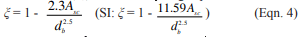
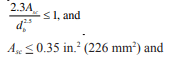
The confinement reinforcement criteria allow a reduced lap splice length when reinforcement is provided transverse to lapped bars. Research has found that the transverse, or confinement, reinforcement increases the lap performance significantly, as long as there is at least one No. 3 (M#10) or larger transverse bar placed within the last 8 in. (203 mm) of each end of the lap (see Figure 1). Because of this effect, calculated lap splice lengths are permitted to be reduced by a confinement factor, ξ, determined using Equation 4:
where
db is the bar diameter of the vertical reinforcement
The reduced lap splice length is not permitted to be less than 36db. The clear space between the transverse bars and the lapped bars may not exceed 1.5 in. (38 mm), and the transverse bars must be fully developed in grouted masonry at the point where they cross the lapped reinforcement (see Figure 1). These provisions are included in Tables 4a through 4d
Table 3—2009 IBC Strength Design Lap Splice Lengths (ref. 2)A
Figure 1—Confinement Reinforcement at Lap Splice
Table 4a—2012 IBC Lap Splice Lengths, f’m = 1,500 psi (10.3 MPa), Reinforcement in Center of Wall (ref. 1)A
Table 4b—2012 IBC Lap Splice Lengths, f’m = 2,000 psi (13.7 MPa), Reinforcement in Center of Wall (ref. 1)A
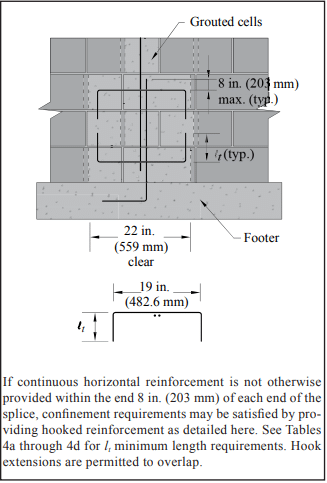
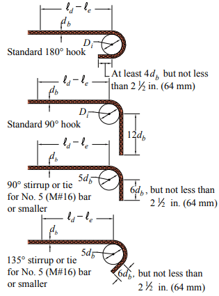
Figure 2 illustrates the requirements for standard hooks, when reinforcing bars are anchored by hooks or by a combination of hooks and development length. These requirements apply to both the 2009 and 2012 IBC, for both allowable stress and strength design. Table 5 lists minimum dimensions and equivalent embedment lengths for standard hooks of various sizes. A combination of hook and development length must be used when the equivalent embedment length of the hook, le, is less than the required minimum development length, ld. In this case, development length equal to (ld – le) must be provided in addition to the hook. This additional development length is measured from the start of the hook (point of tangency with the main portion of the bar).
Figure 2—Standard Hooks
Table 5—Standard Hooks—Dimensions and Equivalent Embedment Lengths
JOINT REINFORCEMENT SPLICES
Joint reinforcement must have a minimum splice length of 6 in. (152 mm) to transfer shrinkage stresses. Slippage of the deformed side wires is resisted by surface bond as well as by mechanical anchorage of the embedded portions of the cross wires.
NOTATIONS:
Asc = area of the transverse bars at each end of the lap splice, in.² (mm²) Di = min. inside diameter of bend for standard hooks, in. (mm) db = nominal diameter of reinforcement, in. (mm) K = the least of the masonry cover, 9db for the 2012 IBC (5db for the 2009 IBC) and the clear spacing between adjacent reinforcement, in. (mm) Fs = allowable tensile stress in reinforcement, psi (MPa) f’m = specified compressive strength of masonry, psi (MPa) fs = calculated tensile or compressive stress in steel, psi (MPa) fy = specified yield strength of steel, psi (MPa) ld = embedment length or lap splice length of straight reinforcement, in. (mm) le = equivalent embedment length provided by standard hooks measured from the start of the hook (point of tangency), in. (mm) lt = length of bar extension of hooked confinement reinforcement, in. (mm) γ = reinforcement size factor ξ = lap splice confinement reinforcement factor
REFERENCES
International Building Code 2012. International Code Council, 2012.
International Building Code 2009. International Code Council, 2009.
Building Code Requirements for Masonry Structures, TMS 402-11 /ACI 530-11/ASCE 5-11. Reported by the Masonry Standards Joint Committee, 2011.
Building Code Requirements for Masonry Structures, TMS 402-08 /ACI 530-08/ASCE 5-08. Reported by the Masonry Standards Joint Committee, 2008.
Steel Reinforcement for Concrete Masonry, TEK 12-04D. Concrete Masonry & Hardscapes Association, 2007.
Structural Welding Code—Reinforcing Steel, AWS D 1.4-05. American Welding Society, 2005.
Standard Specification for Low-Alloy Steel Deformed and Plain Bars for Concrete Reinforcement, ASTM A706/A706M-09b. ASTM International, Inc., 2009.
Building Code Requirements for Structural Concrete and Commentary, ACI 318-11. American Concrete Institute, 2011.
TEK 12-06A, Revised 2013. CMHA and the companies disseminating this technical information disclaim any and all responsibility and liability for the accuracy and the application of the information contained in this publication.
Reinforcement in concrete masonry walls increases strength and ductility, increases resistance to applied loads, and in the case of horizontal reinforcement, also provides increased resistance to shrinkage cracking. This TEK covers non-prestressed reinforcement for concrete masonry construction. Prestressing steel is discussed in Post-Tensioned Concrete Masonry Wall Construction, TEK 03-14 (ref. 1). Unless otherwise noted, the information is based on the 2003 International Building Code (IBC) (ref. 2). For masonry design and construction, the IBC references Building Code Requirements for Masonry Structures and Specification for Masonry Structures (MSJC Code and Specification) (refs. 4, 5). In some cases, the IBC has adopted provisions different from the MSJC provisions. These instances have been noted where applicable.
MATERIALS
Reinforcement used in masonry is principally reinforcing bars and cold-drawn wire products. Wall anchors and ties are usually formed of wire, metal sheets or strips. Table 1 lists applicable ASTM Standards governing steel reinforcement, as well as nominal yield strengths for each steel type.
Table 1—Reinforcement Used in Masonry (ref. 2)
Reinforcing Bars
Reinforcing bars are available in the United States in 11 standard bar sizes designated No. 3 through 11, No. 14 and No. 18 (M#10-36, M#43, M#57). The size of a reinforcing bar is designated by a number corresponding to its nominal diameter. For bars designated No. 3 through No. 8 (M#10-25), the number indicates the diameter in eighths of an inch (mm), as shown in Table 2.
To help address potential problems associated with reinforcement congestion and grout consolidation, the IBC limits the reinforcing bar diameter to the lesser of one-eighth the nominal member thickness, and one-fourth the least dimension of the cell, course or collar joint into which it is placed. For typical single wythe walls, this corresponds to a maximum bar size of No. 8, 9 and 11 for 8-, 10- and 12- in. walls, respectively (M#25, 29 and 36 for 203-, 254- and 305-mm walls). In addition, the following limits apply:
maximum bar size is No. 11 (M#36),
the area of vertical reinforcement may not exceed 6% of the grout space area (i.e., about 1.26 in.² , 1.81 in.² , or 2.40 in.² of vertical reinforcement for 8-, 10- and 12-in. concrete masonry, respectively (815, 1,170 or 1,550 mm² for 203-, 254- and 305-mm units, respectively), and
for masonry designed using strength design procedures, the maximum bar size is No. 9 (M#29) and the maximum area of reinforcement is 4% of the cell area (i.e., about 0.84 in.² , 1.21 in.² , or 1.61 in.² of vertical reinforcement for 8-, 10- and 12-in. concrete masonry, respectively (545, 781 or 1,039 mm² for 203-, 254- and 305-mm units, respectively).
The prescriptive limits on reinforcement sizes, above, are construction-related. Additional design limits to prevent over-reinforcing and brittle failures may also apply depending on the design method used and the design loads resisted. Manufacturers mark the bar size, producing mill identification and type of steel on reinforcing bars (see Figure 1). Note that the bar size indicates the size in SI units per ASTM standards.
The ASTM standards include minimum requirements for various physical properties including yield strength and stiffness. While not all reinforcing bars have a well-defined yield point, the modulus of elasticity, Es , is roughly the same for all reinforcing steels and for design purposes is taken as 29,000,000 psi (200 GPa).
When designing by the allowable stress design method, allowable tensile stress is limited to 20,000 psi (138 MPa) for Grade 40 or 50 reinforcing bars and 24,000 psi (165 MPa) for Grade 60 reinforcing bars. For reinforcing bars enclosed in ties, such as those in columns, the allowable compressive stress is limited to 40% of the specified yield strength, with a maximum of 24,000 psi (165 MPa). For strength design, the nominal yield strength of the reinforcement is used to size and distribute the steel.
Table 2—Reinforcing Bar Nominal Properties
Figure 1—ASTM Standard Bar Identifi cation Marks
Cold-Drawn Wire
Cold-drawn wire for joint reinforcement, ties or anchors varies from W1.1 to W4.9 (MW7 to MW32) with the most popular size being W1.7 (MW11). Table 3 shows standard wire sizes and properties. Because the IBC limits the size of joint reinforcement to one half the joint thickness, the practical limit for wire diameter is 3/16 in. (W2.8, 4.8 mm, MW18) for a ⅜ in. (9.5 mm) bed joint. Wire for masonry is plain with the exception that side wires for joint reinforcement are deformed by means of knurling wheels.
Stress-strain characteristics of reinforcing wire have been determined by extensive testing programs. Not only is the yield strength of cold-drawn wire close to its ultimate strength, but the location of the yield point is not clearly indicated on the stress-strain curve. ASTM A 82 (ref. 15) defines yield as the stress determined at a strain of 0.005 in./in. (mm/mm).
Table 3—Properties of Wire For Masonry
CORROSION PROTECTION
Grout, mortar and masonry units usually provide adequate protection for embedded reinforcement provided that minimum cover and clearance requirements are met. Reinforcement with a moderate amount of rust, mill scale or a combination is allowed to be used without cleaning or brushing, provided the dimensions and weights (including heights of deformations) of a cleaned sample are not less than those required by the applicable ASTM standard. When additional corrosion protection is needed, reinforcement can be galvanized or epoxy coated.
Joint Reinforcement
Carbon steel can be protected from corrosion by coating the steel with zinc (galvanizing). The zinc protects in two ways: first, as a barrier separating the steel from oxygen and water, and second during the corrosion process, the zinc is sacrificed before the steel is attacked. Increasing the zinc coating thickness improves the level of corrosion protection.
Required levels of corrosion protection increase with the severity of exposure. When used in exterior walls or in interior walls exposed to a mean relative humidity over 75%, carbon steel joint reinforcement must be hot-dip galvanized or epoxy-coated, or stainless steel joint reinforcement must be used. When used in interior walls exposed to a mean relative humidity less than or equal to 75%, it can be mill galvanized, hot-dip galvanized, or be stainless steel. The corresponding minimum protection levels are:
Mill galvanized—ASTM A 641 (ref. 16) 0.1 oz/ft² (0.031 kg/m²)
Hot-dip galvanized—ASTM A 153 (ref. 17), Class B, 1.5 oz/ft² (458 g/m²)
Epoxy-coated—ASTM A 884 (ref. 18) Class A, Type 1 ≥ 7 mils (175 µm) (ref. 3). Note that both the 2003 IBC and 2002 MSJC code incorrectly identify Class B, Type 2 epoxy coated joint reinforcement, which is not applicable for masonry construction.
In addition, joint reinforcement must be placed so that longitudinal wires are embedded in mortar with a minimum cover of ½ in. (13 mm) when not exposed to weather or earth, and ⅝ in. (16 mm) when exposed to weather or earth.
Reinforcing Bars
A minimum amount of masonry cover over reinforcing bars is required to protect against steel corrosion. This masonry cover is measured from the nearest exterior masonry surface to the outermost surface of the reinforcement, and includes the thickness of masonry face shells, mortar and grout. The following minimum cover requirements apply:
masonry exposed to weather or earth bars larger than No. 5 (M#16) …………………….2 in. (51 mm) No. 5 (M#16) bars or smaller……………………1½ in. (38 mm)
masonry not exposed to weather or earth … 1½ in. (38 mm)
PLACEMENT
Installation requirements for reinforcement and ties help ensure that elements are placed as assumed in the design, and that structural performance is not compromised due to mislocation. These requirements also help minimize corrosion by providing for a minimum amount of masonry and grout cover around reinforcing bars, and providing sufficient clearance for grout and mortar to surround reinforcement and accessories so that stresses can be properly transferred.
Reinforcing Bars
Tolerances for placing reinforcing bars are:
variation from d for walls and fl exural elements: d ≤ 8 in. (203 mm) ………………………. ±½ in. (13 mm) 8 in. (203 mm) < d ≤ 24 in. (610 mm) ±1 in. (25 mm) d > 24 in. (610 mm) ……………………. ±1¼ in. (32 mm)
for vertical bars in walls ………..±2 in. (51 mm) from the specified location along the length of the wall.
In addition, a minimum clear distance between reinforcing bars and the adjacent (interior of cell) surface of a masonry unit of ¼ in. (6.4 mm) for fine grout or ½ in. (13 mm) for coarse grout must be maintained so that grout can flow around the bars.
DEVELOPMENT
Development length or anchorage is necessary to adequately transfer stresses between the reinforcement and the grout in which it is embedded. Reinforcing bars can be anchored by embedment length, hook or mechanical device. Reinforcing bars anchored by embedment length rely on interlock at the bar deformations and on sufficient masonry cover to prevent splitting from the reinforcing bar to the free surface. Detailed information and requirements for development, splice and standard hooks are contained in TEK 12-06A, Splices, Development and Standard Hooks for CM Based on the 2009 & 2012 IBC (ref. 19).
International Building Code 2003. International Code Council, 2003.
International Building Code 2006. International Code Council, 2006.
Building Code Requirements for Masonry Structures, ACI 530-02/ASCE 5-02/TMS 402-02. Reported by the Masonry Standards Joint Committee, 2002.
Specification for Masonry Structures, ACI 530.1-02/ASCE 6-02/TMS 602-02. Reported by the Masonry Standards Joint Committee, 2002.
Standard Specification for Deformed and Plain Billet-Steel Bars for Concrete Reinforcement, ASTM A615/A615M-00. ASTM International, Inc., 2000.
Standard Specification for Low-Alloy Steel Deformed and Plain Bars for Concrete Reinforcement, ASTM A706/A706M- 01. ASTM International, Inc., 2001.
Standard Specification for Zinc-Coated (Galvanized) Steel Bars for Concrete Reinforcement, A767/A767M-00b. ASTM International, Inc., 2000.
Standard Specification for Epoxy-Coated Steel Reinforcing Bars, A775/A775M-01. ASTM International, Inc., 2001.
Standard Specification for Rail-Steel and Axle-Steel Deformed Bars for Concrete Reinforcement, A996/A996M-00. ASTM International, Inc., 2000.
Standard Specification for Masonry Joint Reinforcement, ASTM A951-00. ASTM International, Inc., 2000.
Standard Specification for Stainless and Heat-Resisting Steel Wire, ASTM A580-98. ASTM International, Inc., 1998.
Standard Specification for Steel Wire, Deformed, for Concrete Reinforcement, A496/A496M-01. ASTM International, Inc., 2001.
Manual of Standard Practice, MSP 1-01. Concrete Reinforcing Steel Institute, 2001.
Standard Specification for Steel Wire, Plain, for Concrete Reinforcement, ASTM A82-01. ASTM International, Inc., 2001.
Standard Specification for Zinc-Coated (Galvanized) Carbon Steel Wire, ASTM A641-98. ASTM International, Inc., 1998.
Standard Specification for Zinc Coating (Hot-Dip) on Iron and Steel Hardware, ASTM A153-01a. ASTM International, Inc., 2001.
Standard Specification for Epoxy-Coated Steel Wire and Welded Wire Fabric for Reinforcement, ASTM A884/A884M-99. ASTM International, Inc., 1999.
Reinforcement Detailing Requirements for Concrete Masonry, TEK 12-06A. Concrete Masonry & Hardscapes Association, 2007.
TEK 12-04D, Revised 2006. Disclaimer: Although care has been taken to ensure the enclosed information is as accurate and complete as possible, CMHA does not assume responsibility for errors or omissions resulting from the use of this TEK.
Standard joint reinforcement for concrete masonry is a factory fabricated welded wire assembly consisting of two or more longitudinal wires connected with cross wires forming a truss or ladder configuration. It was initially conceived primarily to control wall cracking associated with thermal or moisture shrinkage or expansion and as an alternative to masonry headers when tying masonry wythes together. Note that horizontal steel requirements for crack control can be met using joint reinforcement or reinforcing bars. See Crack Control Strategies for Concrete Masonry Construction, CMU TEC-009-23 (ref. 6).
Joint reinforcement also increases a wall’s resistance to horizontal bending, but is not widely recognized by the model building codes for structural purposes. In some instances, it may be used in design for flexural resistance or to meet prescriptive seismic requirements.
This TEK discusses the code and specification requirements for joint reinforcement and presents a general discussion of the function of joint reinforcement in concrete masonry walls. Detailed information on additional uses for joint reinforcement can be found in other TEK as referenced throughout this publication.
MATERIALS
Reinforcement types used in masonry principally are reinforcing bars and cold-drawn wire products. Joint reinforcement is governed by Standard Specification for Masonry Joint Reinforcement, ASTM A 951 (ref. 1), or Standard Specification for Stainless Steel Wire, ASTM A 580/580M Type 304 or Type 316 (ref. 2), if the joint reinforcement is stainless steel according to the Specification for Masonry Structures (ref. 3). Cold-drawn wire for joint reinforcement varies from W1.1 to W4.9 (11 gage to 1/4 in. diameter; MW7 to MW32), the most popular size being W1.7 (9 gage, MW11). Wire for masonry is plain, except side wires for joint reinforcement are deformed by means of knurling wheels.
Because Building Code Requirements for Masonry Structures (ref. 4) limits the size of joint reinforcement to one half the joint thickness, the practical limit for wire diameter is W2.8, (3/16 in., MW17) for a 3/8 in. (9.5 mm) bed joint. Joint reinforcement of this thickness may be difficult to install however, if a uniform mortar joint thickness of 3/8 in. (9.5 mm) is to be maintained.
Types of Joint Reinforcement
Reflecting its multiple purposes in masonry walls, joint reinforcement comes in several configurations. One longitudinal wire is generally required for each bed joint (i.e., two wires for a typical single wythe wall), but code or specification requirements may dictate otherwise. Typical joint reinforcement spacing is 16 in. (406 mm) on center. Adjustable ties, tabs, third wires and seismic clips are also available in combination with joint reinforcement for multi-wythe and veneer walls.
Ladder-type joint reinforcement (Figure 1) consists of longitudinal wires flush welded with perpendicular cross wires, creating the appearance of a ladder. It is less rigid than truss type joint reinforcement and is recommended for multi-wythe walls with cavity spaces or unfilled collar joints. This permits the two wythes to move independently, yet still transfers outof-plane loads from the exterior masonry to the interior masonry wall. Cross wires 16 in. (406 mm) on center should be used for reinforced concrete masonry construction, to keep cross wires out of the core spaces, thus preventing them from interfering with the placement of vertical reinforcement and grout.
Truss-type joint reinforcement (Figure 2) consists of longitudinal wires connected with diagonal cross wires. This shape is stiffer in the plane of the wall than ladder-type joint reinforcement and if used to connect multiple wythes restricts differential movement between the wythes. For this reason, it should be used only when differential movement is not a concern, as in single wythe concrete masonry walls. Because the diagonal cross wires may interfere with the placement of vertical reinforcing steel and grout, truss type joint reinforcement should not be used in reinforced or grouted walls.
Tabs, ties, anchors, third wires and seismic clips of assorted configurations are often used with the joint reinforcement to produce a system that works to: control cracking; bond masonry wythes together; anchor masonry; and, in some cases, resist structural loads. Tie and anchor spacing and other requirements are included in Anchors and Ties for Masonry, TEK 12-01B (ref.5).
Recommendations for the use of some of the different types of joint reinforcement are listed in Table 1.
CORROSION PROTECTION
Grout, mortar and masonry units usually provide adequate protection for embedded reinforcement, provided that minimum cover and clearance requirements are met.
Coating Requirements
The carbon steel in joint reinforcement can be protected from corrosion by coating with zinc (galvanizing). The zinc protects steel in two ways. First, it provides a barrier between the steel and oxygen and water. Second, during the corrosion process, the zinc provides a sacrificial coating. The protective value of the zinc coating increases with increased coating thickness; therefore the required amount of galvanizing increases with the severity of exposure, as listed below (refs. 3, 4):
Interior walls exposed to a mean relative humidity less than or equal to 75%: Mill galvanized, ASTM A 641 (0.1oz/ft2) (0.031 kg/m2) Hot-dip galvanized, ASTM A 153 (1.5 oz/ft2) (458 g/m2) Stainless steel AISI Type 304 or Type 316 conforming to ASTM A 580
Exterior walls or interior walls exposed to a mean relative humidity > 75%: Hot-dip galvanized, ASTM A 153 (1.5 oz/ft2 (0.46 kg/m2) Epoxy coated, ASTM A 884 Class A Type 1, > 7 mils (175 mm) Stainless steel AISI Type 304 or Type 316 conforming to ASTM A 580
Cover Requirements
Specification for Masonry Structures also lists minimum cover requirements for joint reinforcement as a further means of corrosion protection. It must be placed so that longitudinal wires are embedded in mortar with a minimum cover of:
1/2 in. (13 mm) when not exposed to weather or earth,
5/8 in. (16 mm) when exposed to weather or earth.
PRESCRIPTIVE CODE REQUIREMENTS
Building Code Requirements for Masonry Structures includes prescriptive requirements for joint reinforcement. There are multiple uses for joint reinforcement in masonry structures. Joint reinforcement can be used to provide crack control, horizontal reinforcement, and bond for multiple wythes, corners and intersections. The following list highlights only those requirements specific to joint reinforcement. Crack control topics are covered in CMU-TEC-009-23 (ref. 6). For information on anchors and ties, see Anchors and Ties for Masonry, TEK 12-01B (ref. 5). There is also a useful discussion on joint reinforcement as structural reinforcing in Steel Reinforcement for Concrete Masonry, TEK 12-04D (ref. 7).
General Requirements for Joint Reinforcement
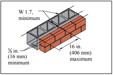
For masonry in other than running bond: Horizontal reinforcement shall be 0.00028 times the gross vertical cross-sectional area of the wall. This requirement can be met with joint reinforcement placed in the horizontal bed joints. For 8in. (203-mm) masonry walls, this amounts to W1.7 (9 gage, MW11) joint reinforcement every other course. There are additional criteria for stack bond masonry in Seismic Design Categories D, E and F.
Seismic Requirements: In Seismic Design Category C and higher (for concrete masonry other than veneer), horizontal joint reinforcement spaced not more than 16 in. (406 mm) on center vertically with at least two wires of W1.7 (MW11) is required. Horizontal reinforcement also must be provided at the bottom and top of all wall openings and must extend at least 24 in. (610 mm) past the opening. Additional details on seismic requirements, including shear walls, are covered in Seismic Design and Detailing Requirements for Masonry Structures, CMHA TEK 14-18B (ref. 8).
Allowable Stress Design Requirements
In addition to the requirements above, concrete masonry walls designed by the allowable stress method and bonded by wall ties must have a maximum tie spacing of 36 in. (914 mm) horizontally and 24 in. (610 mm) vertically. Joint reinforcement cross wires can be used in place of wall ties to meet this requirement.
When the walls are designed for noncomposite action, truss-type joint reinforcing is not to be used for tying the wythes.
Combination joint reinforcement with tabs or adjustable ties are popular options for bonding multiwythe walls and are governed by additional code requirements.
Empirical Design Requirements
When two wythes of masonry are bonded with joint reinforcement, at least one cross wire must serve as a tie for each 22/3 ft2 (0.25 m2) of wall area. The vertical spacing of the joint reinforcement can not exceed 24 in. (610 mm), and the cross wires must be W1.7 (9 gage, MW11) minimum, without drips, and embedded in mortar.
Intersecting walls, when depending on each other for lateral support, can be anchored by several prescriptive methods including the use of joint reinforcement spaced no more than 8 in. (203 mm) on center vertically. The longitudinal wires must extend at least 30 in. (762 mm) in each direction at the intersection and be at least W1.7 (9 gage, MW11).
Interior nonloadbearing wall intersections may be anchored by several prescriptive methods, including joint reinforcement at a maximum spacing of 16 in. (406 mm) o.c. vertically.
Requirements for Use in Veneer
Prescriptive requirements for joint reinforcement in masonry veneer are included in Building Code Requirements for Masonry Structures, Chapter 6. These provisions are limited to areas where the basic wind speed does not exceed 110 mph (177 km/hr) as listed in ASCE 7-02 (ref. 9). Additional limitations are covered in the Code. The information below is for joint reinforcement or the joint reinforcement portion of a tie/anchor system. For information on anchor and tie requirements see Concrete Masonry Veneers, TEK 03-06C (ref. 10).
Ladder-type or tab-type joint reinforcement is permitted in veneer construction with the cross wires used to anchor the masonry veneer. Minimum longitudinal and cross wire size is W1.7 (9 gage, MW11), and maximum spacing is 16 in. (406 mm) on center vertically.
Adjustable anchors combined with joint reinforcement may be used as anchorage with the longitudinal wire of the joint reinforcement being W1.7 (9 gage, MW11) minimum.
Joint reinforcement may also be used to anchor masonry veneer to masonry provided the maximum distance between the inside face of the veneer and the outside face of the concrete masonry backup wythe is 4 1/2 in. (114 mm).
In Seismic Design Categories E and F, the 2005 edition of Building Code Requirements for Masonry Structures requires continuous single wire joint reinforcement, W1.7 (9 gage, MW11) minimum, in the veneer wythe at a maximum spacing of 18 in. (457 mm) on center vertically. Clips or hooks must attach the wire to the joint reinforcement. The International Building Code 2003 (ref. 11) also mandates this requirement for Seismic Design Category D.
Anchor spacings, and, as a result, possibly joint reinforcement spacing, are reduced for Seismic Design Categories D, E and F and in high wind areas.
Requirements for Use in Glass Unit Masonry
Horizontal joint reinforcement is to be spaced no more than 16 in. (406 mm) on center, located in the mortar bed joint, and must not span across movement joints.
Minimum splice length is 6 in. (152 mm).
Joint reinforcement must be placed immediately above and below openings in the panel.
Joint reinforcement must have at least 2 parallel, longitudinal wires of size W1.7 (9 gage, MW11) and have welded cross wires of W1.7 (9 gage, MW11) minimum.
INSTALLATION
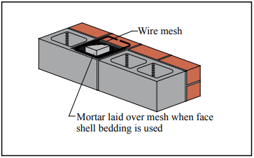
Joint reinforcement installation is a routine task for masons. The joint reinforcement is placed on the face shells and mortar is placed over it. Cover requirements must be maintained. Installing the correct type of joint reinforcement with the specified corrosion resistant coating is important, as is making sure it is installed at the proper spacings and locations. Quality assurance provisions related to joint reinforcement generally include:
Submittals
Material Certificate indicating compliance should include:
material meets specified ASTM standard,
corrosion protection specified has been supplied,
configuration specified has been supplied, and
other criteria as required or specified.
Inspection
Oil, dirt and other materials detrimental to bond should be removed. Light rust and mill scale are permissible.
Cover requirements are met.
Splices are a minimum of 6 in. (152 mm) (see Figure 3) to properly transfer tensile stresses. Tying is not necessary. Construction documents may specify longer splices, especially if the joint reinforcement is being used as part of the structural horizontal reinforcing steel.
Verify that joint reinforcement utilized for crack control does not continue through movement joints.
If ties or anchors are part of the joint reinforcement, check that embedment in the adjoining wythe, alignment and spacing are within specified values.
REFERENCES
Standard Specification for Masonry Joint Reinforcement, ASTM A 951-02. ASTM International, 2002.
Standard Specification for Stainless Steel Wire, ASTM A 580/580M-98(2004). ASTM International, 2004.
Specification for Masonry Structures, ACI 530.1-05/ASCE 6 05/TMS 602-05. Reported by the Masonry Standards Joint Committee, 2005.
Building Code Requirements for Masonry Structures, ACI 530 05/ASCE 5-05/TMS 402-05. Reported by the Masonry Standards Joint Committee, 2005.
Anchors and Ties for Masonry, TEK 12-01B, Concrete Masonry & Hardscapes Association 2011.
Crack Control Strategies for Concrete Masonry Construction, CMU-TEC-009-23, 2023.
Steel Reinforcement for Concrete Masonry, TEK 12-04D, Concrete Masonry & Hardscapes Association, 2023.
Seismic Design and Detailing Requirements for Masonry Structures, TEK 14-18B, Concrete Masonry & Hardscapes Association, 2003.
Minimum Design Loads for Buildings and Other Structures, ASCE 7-02, American Society of Civil Engineers, 2002.
Masonry connectors can be classified as wall ties, anchors or fasteners. Wall ties connect one masonry wythe to an adjacent wythe. Anchors connect masonry to a structural support or frame. Fasteners connect an appliance to masonry. This TEK covers metal wall ties and anchors. Fasteners are discussed in TEK 12-05 (ref. 1).
The design of anchors and ties is covered by the International Building Code and Building Code Requirements for Masonry Structures (refs. 2, 3).These provisions require that connectors be designed to resist applied loads and that the type, size and location of connectors be shown or indicated on project drawings. This TEK provides a guide to assist the designer in determining anchor and tie capacity in accordance with the applicable standards and building code requirements.
DESIGN CRITERIA
Connectors play a very important role in providing structural integrity and good serviceability. As a result, when selecting connectors for a project, designers should consider a number of design criteria. Connectors should:
Transmit out-of-plane loads from one wythe of masonry to another or from masonry to its lateral support with a minimum amount of deformation. It is important to reduce the potential for cracking in masonry due to deflection. There is no specific criteria on connector stiffness, but some authorities suggest that a stiffness of 2,000 lb/in. (350 kN/m) is a reasonable target.
Allow differential in-plane movement between two masonry wythes connected with ties. This is especially significant as more insulation is used between the outer and inner wythes of cavity walls and where wythes of dissimilar materials are anchored together. On the surface, it may appear that this criterion is in conflict with Item 1, but it simply means that connectors must be stiff in one direction (out-of-plane) and flexible in the other (in plane). Note that some connectors allow much more movement than unreinforced masonry can tolerate (see ref. 27 for a discussion of potential masonry wall movements). In order to preserve the in-plane and out-of-plane wall tie stiffness, current codes (refs. 2, 3) allow cavity widths up to 4 1/2 in. (114 mm) without performing wall tie analysis. With an engineered analysis of the wall ties, cavity widths may be significantly increased to accommodate thicker insulation.
Meet applicable material requirements:
plate and bent-bar anchors—ASTM A36 (ref. 4)
sheet-metal anchors and ties—ASTM A1008 (ref. 5)
wire anchors and ties—ASTM A82 (ref. 6), and adjustable wire ties must also meet the requirements illustrated in Figure 1
wire mesh ties – ASTM A185 (ref. 7)
Provide adequate corrosion protection. Where carbon steel ties and anchors are specified, corrosion protection must be provided by either galvanizing or epoxy coating in conformance with the following (ref. 8):
A. Galvanized coatings:
Joint reinforcement in interior walls exposed to a mean relative humidity of 75% or less—ASTM A641 (ref. 13), 0.1 oz zinc/ft2 (0.031 kg zinc/m2)
Joint reinforcement, wire ties and wire anchors, exterior walls or interior walls exposed to a mean relative humidity greater than 75%—ASTM A153 (ref. 14), 1.5 oz zinc/ft2 (458 g/m2)
Sheet metal ties or anchors, interior walls exposed to a mean relative humidity of 75% or less—ASTM A653 (ref. 15) Coating Designation G60
Sheet metal ties or anchors, exterior walls or interior walls exposed to a mean relative humidity greater than 75%—ASTM A153 Class B
Steel plates and bars, exterior walls or interior walls exposed to a mean relative humidity greater than 75%—ASTM A123 (ref. 16) or ASTM A153 Class B
Plate and bent-bar anchors—ASTM A480 and ASTM A666 (refs. 10, 11)
Sheet metal anchors and ties—ASTM A480 and ASTM A240 (refs. 10, 12)
Wire ties and anchors—ASTM A580
B. Epoxy coatings:
Joint reinforcement—ASTM A884 (ref. 17) Class A Type 1 > 7 mils (175 µm)
Wire ties and anchors—ASTM A899 (ref. 18) Class C 20 mils (508 µm)
Sheet metal ties and anchors—20 mils (508 µm) per surface or per manufacturer’s specification
Where stainless steel anchors and ties are specified, Specification for Masonry Structures (ref. 8) requires that AISI Type 304 or 316 stainless steel be provided that complies with:
Joint reinforcement—ASTM A580 (ref. 9)
Accommodate construction by being simple in design and easy to install. Connectors should not be so large and cumbersome as to leave insufficient room for mortar in the joints, which can result in a greater tendency to allow water migration into the wall. In the same way, connectors should readily accommodate insulation in wall cavities.
WALL TIE AND ANCHOR REQUIREMENTS
Multiwythe Masonry Wall Types
Wall ties are used in all three types of multiwythe walls (composite, noncomposite and veneer), although some requirements vary slightly depending on the application. The primary differences between these wall systems are in construction details and how the applied loads are assumed to be distributed.
Composite walls are designed so that the masonry wythes act together as a single structural member. This requires the masonry wythes to be connected by masonry headers or by a mortar- or grout filled collar joint and wall ties to help ensure adequate load transfer. TEKs 16-01A and 16-02B (refs. 19, 20) more fully describe composite walls.
In noncomposite masonry (also referred to as a cavity wall), wythes are connected with metal wall ties, but they are designed such that each wythe individually resists the loads imposed on it. Noncomposite walls are discussed in TEKs 16-01A and 16-04A (refs. 19, 21).
In a veneer wall, the backup wythe is designed as the load-resisting system, with the veneer providing the architectural wall finish. Information on veneer walls can be found in TEKs 05-01B and 03 06C (refs. 22, 23). Note that although a cavity wall is defined as a noncomposite masonry wall (ref. 3), the term cavity wall is also commonly used to describe a veneer wall with masonry backup.
Building Code Requirements for Masonry Structures also includes empirical requirements for wire wall ties and strap-type ties used to connect intersecting walls. These requirements are covered in TEK 14-08B (ref. 24).
Wall Ties
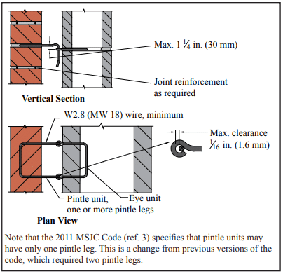
Wire wall ties can be either one piece unit ties, adjustable two piece ties, joint reinforcement or prefabricated assemblies made up of joint reinforcement and adjustable ties (see Figure 2). Note that the 2011 edition of Specification for Masonry Structures allows adjustable pintle ties to have only one leg (previously, two legs were required for this type of wall tie).
Wall ties do not have to be engineered unless the nominal width of the wall cavity is greater than 4 1/2 in. (114 mm). These wall tie analyses are becoming more common as a means to accommodate more thermal insulation in the wall cavity. Masonry cavities up to 14 in. (356 mm) have been engineered. Of note for these analyses is that the span of wire is a more critical factor than cavity width, i.e. the span length of the pintel component typically controls the mode of failure.
The prescribed size and spacing is presumed to provide connections that will be adequate for the loading conditions covered by the code. These wall tie spacing requirements can be found in TEK 03-06C (for veneers) and TEK 16-01A (for composite and noncomposite walls). Note that truss-type joint reinforcement is stiffer in the plane of a wall compared to ladder-type, so it is more restrictive of differential movement. For this reason, laddertype joint reinforcement is recommended when significant differential movement is expected between the two wythes or when vertical reinforcement is used. See TEK 12-02B (ref. 25) for more information.
Additional tests are needed for adjustable anchors of different configurations and for one piece anchors. Proprietary anchors are also available. Manufacturers of proprietary anchors should furnish test data to document comparability with industry-tested anchors.
Anchors are usually designed based on their contributory area. This is the traditional approach, but some computer models suggest that this approach does not always reflect the actual behavior of the anchorage system. However, there is currently no accepted computer program to address this point, so most designers still use the contributory area approach with a factor of safety of three. The use of additional anchors near the edges of wall panels is also recommended and required around large openings and within 12 in. (305 mm) of unsupported edges.
CONSTRUCTION
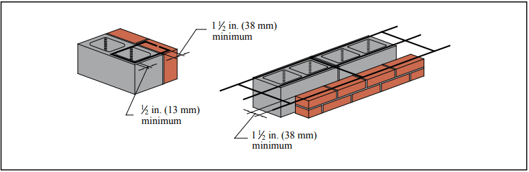
When typical ties and anchors are properly embedded in mortar or grout, mortar pullout or pushout will not usually be the controlling mode of failure. Specification for Masonry Structures requires that connectors be embedded at least 1 1/2 in. (38 mm) into a mortar bed of solid units. The required embedment of unit ties in hollow masonry is such that the tie must extend completely across the hollow units. Proper embedment can be easily attained with the use of prefabricated assemblies of joint reinforcement and unit ties. Because of the magnitude of loads on anchors, it is recommended that they be embedded in filled cores of hollow units. See TEK 03-06C for more detailed information.
REFERENCES
Fasteners for Concrete Masonry, TEK 12-05. Concrete Masonry & Hardscapes Association, 2005.
International Building Code. International Code Council, 2012.
Building Code Requirements for Masonry Structures, TMS 402-11/ACI 530-11/ASCE 5-11. Reported by the Masonry Standards Joint Committee, 2011.
Standard Specification for Carbon Structural Steel, A36-ASTM International, 2008.
Standard Specification for Steel, Sheet, Cold-Rolled, Carbon, Structural, High-Strength Low-Alloy with Improved Formability, A1008-11. ASTM International, 2011.
Standard Specification for Steel Wire, Plain for Concrete Reinforcement, A82-07. ASTM International, 2007.
Standard Specification for Steel Welded Wire Reinforcement, Plain, for Concrete, A185-07. ASTM International, 2007.
Specification for Masonry Structures, TMS 602 -11/ACI 530.1-11/ASCE 6-11. Reported by the Masonry Standards Joint Committee, 2011.
Standard Specification for Stainless Steel Wire, ASTM A580-08. ASTM International, 2008.
Standard Specification for General Requirements for Flat Rolled Stainless and Heat-Resisting Steel Plate, Sheet, and Strip, ASTM A480-11a. ASTM International, 2011.
Standard Specification for Annealed or Cold-Worked Austenitic Stainless Steel, Sheet, Strip, Plate and Flat Bar, ASTM A666-10. ASTM International, 2010.
Standard Specification for Chromium and Chromium Nickel Stainless Steel Plate, Sheet and Strip for Pressure Vessels and for General Applications, ASTM A240-11a. ASTM International, 2011.
Standard Specification for Zinc-Coated (Galvanized) Carbon Steel Wire, ASTM A641-09a. ASTM International, 2009.
Standard Specification for Zinc Coating (Hot-Dip) on Iron and Steel Hardware, ASTM A153-09. ASTM International, 2009.
Standard Specification for Steel Sheet, Zinc-Coated Galvanized or Zinc-Iron Alloy-Coated Galvannealed by the Hot-Dip Process, ASTM A653-10. ASTM International, 2010.
Standard Specification for Zinc (Hot-Dip Galvanized) Coating on Iron and Steel Products, ASTM A123-09. ASTM International, 2009.
Standard Specification for Epoxy-Coated Steel Wire and Welded Wire Fabric for Reinforcement, ASTM A884-06. ASTM International, 2006.
Standard Specification for Steel Wire Epoxy Coated, ASTM A899-91(2007). ASTM International, 2007.
Empirical Design of Concrete Masonry Walls, TEK 14-08B, Concrete Masonry & Hardscapes Association, 2008.
Joint Reinforcement for Concrete Masonry, TEK 12-02B, Concrete Masonry & Hardscapes Association, 2005.
Porter, Max L., Lehr, Bradley R., Barnes, Bruce A., Attachments for Masonry Structures, Engineering Research Institute, Iowa State University, February 1992.
Crack Control Strategies for Concrete Masonry Construction, CMU-TEC-009-23, Concrete Masonry & Hardscapes Association, 2023.
Masonry is often specified because of its aesthetic versatility. Combining masonry units of different size, color and finish provides a virtually limitless palette. Often, exterior concrete masonry walls incorporate clay brick, or concrete masonry is used in clay brick walls as accent bands. The bands add architectural interest to the wall and can also help hide horizontal elements such as flashing and expansion joints. However, combining these two materials within one wythe of masonry requires special detailing due to their different material properties.
In general, all masonry walls should be designed and detailed to accommodate anticipated movement resulting from volume changes in the masonry materials themselves. For example, vertical control joints and horizontal joint reinforcement can be incorporated into concrete masonry walls to control cracking and still allow horizontal shrinkage of the concrete masonry units to occur without introducing undue stress into the wall. Similarly, clay masonry walls incorporate vertical and horizontal expansion joints to allow the clay to expand without distress. When both clay and concrete masonry units are used in the same masonry wythe, detailing is required to accommodate concrete masonry shrinkage and clay masonry expansion occurring side by side. Concrete masonry is a hydraulic cement product and as such requires water for cement hydration, which hardens the concrete. Therefore, concrete masonry units are relatively wet at the time of manufacture and from that time on tend to shrink as the units dry. Conversely, clay masonry units are very dry subsequent to firing during the manufacturing process and then tend to expand as they pick up moisture from the atmosphere and from mortar as they are laid. Without due consideration of these opposing movements, cracking can result. In veneers, the cracking is primarily an aesthetic issue, as any water that penetrates the veneer through cracks between the two materials drains down the cavity and is directed out of the wall via flashing and weep holes.
BANDING DETAILS
When detailing a wall to accommodate movement, the design goal is to allow the movement to occur (as restraint will cause cracking) while providing appropriate support. The recommendations that follow are based on a record of successful performance in many locations across the United States. These can be adjusted as needed to suit local conditions and/or experience.
In general, several strategies are used to accommodate movement. These include movement joints (control joints in concrete masonry and expansion joints in clay masonry); horizontal joint reinforcement to take tension due to concrete masonry shrinkage and help keep any cracks that occur closed; and sometimes horizontal joints to allow longitudinal movement. In veneers, it is particularly important that the band, as well as the wall panel above and below the band be supported by wall ties. Wall ties should be installed within 12 in. (305 mm) of the top and bottom of the band to help ensure the surrounding masonry is adequately supported.
In addition, using a lower compressive strength mortar helps ensure that if cracks do occur, they occur in the mortar joint rather than through the unit. Type N mortar is often specified for veneers, because it tends to be more flexible than other mortar types.
Concrete Masonry Band in Clay Brick Wall
Figure 1a shows a two-course high concrete masonry band in a clay brick exterior wythe of a cavity wall. With this type of construction, the following practices are employed to minimize the potential for cracking.
Horizontal joint reinforcement is placed in the mortar joints above and below the band to take stress from the differential movement in that plane. For bands higher than two courses, joint reinforcement should also be placed within the band itself at a spacing of 16 in. (406 mm) on center vertically. Ideally, the joint reinforcement and ties should be placed in alternate joints so that one does not interfere with placement of the other. Some designers, however, prefer placing joint reinforcement in every bed joint in the concrete masonry band, particularly if the aspect ratio of the band is high. In this case, a tie which accommodates both tie and wire in the same mortar joint should be used, such as a seismic clip type wall tie.
Although the detail in Figure 1a has demonstrated good performance in many areas of the United States, there are locations where use of bond breaks at the top and bottom of the band is preferred (see Figure 1b) A local masonry industry representative should be contacted for further information on which detail has been more successful in a given location.
Figure 1b shows a slip plane incorporated into the interfaces between the concrete and clay masonry to allow unrestrained longitudinal movement between the two materials. This can be accomplished by placing building paper, polyethylene, flashing or a similar material in the horizontal bed joints above and below the band. When hollow masonry units are used for the band, the slip plane below the band should incorporate flashing, so that any water draining down the cores of the band can be directed out of the wall at that point.
When slip planes are used, joint reinforcement should be incorporated into the concrete masonry band. The exposed mortar joint at the top and bottom of the band should be raked back and sealed with an appropriate sealant to prevent water penetration at these joints. Note that this construction is typically more expensive than the detail shown in Figure 1a.
In addition to joint reinforcement, reduced spacing of expansion joints in the wall is recommended to reduce the potential for cracking. Experience has shown that vertical expansion joints in the clay masonry should extend through the concrete masonry band as well, and be placed at a maximum of 20 ft (6.1 m) along the length of the wall. Although concrete masonry construction typically requires control joints rather than expansion joints, control joints should not be used in the concrete masonry band at the expansion joint locations.
Note that local experience may require reducing the expansion joint spacing to 16 ft (4.9 m). If brick vertical expansion joint spacing does exceed 20 ft (6.1 m), consider placing an additional vertical movement joint through the concrete masonry accent band near mid panel with joint reinforcement continuous through that joint. The continuous joint reinforcement in this location helps keep the clay brick above and below the band from cracking as the concrete masonry shrinks.
Bands only one course high must be detailed to incorporate joint reinforcement and wall ties in the joints above and below the band (see Figure 2).
When concrete masonry banding is used over a wood stud backup, similar provisions apply (see Figure 3). It is imperative that joint reinforcement be used in the concrete masonry band, even if it is not used in the surrounding clay brick masonry.
Clay Brick Band in Concrete Masonry Wall
The recommendations to control differential movement for clay brick masonry bands in concrete masonry are very similar to those for a concrete masonry band in clay brick veneer: joint reinforcement above and below the band and wall ties within the band. Seismic clip type wall ties are recommended, as they provide an adjustable wall tie and joint reinforcement in one assembly.
With this construction, it is imperative that the veneer control joint not contain mortar as it goes through effectiveness. Note that although control joints in structural masonry walls must permit free longitudinal movement while resisting lateral or out-of plane shear loads, veneers are laterally supported by the backup and do not require a shear key.
In single wythe construction as shown in Figure 5, flashing and weep holes are used above the accent band to facilitate removal of any water that may accumulate in the wall. The use of two reduced thickness concrete masonry units allows flashing to be placed within the wall without causing a complete horizontal bond break at the flashing.
In reinforced walls (Figure 5b), flashing and weeps are also used. On the wall interior, rather than using reduced thickness units, a full size unit is cut to fit to allow adequate space for the reinforcement and grout.
Concrete masonry screen walls are used in every part of every country on the globe, on every conceivable style of building, and for a wide variety of purposes. Created originally as a functional building element, the screen wall combines privacy with observation, interior light with shade and solar heat reduction, and airy comfort with wind control for both interior and exterior applications. Curtain walls, fences, sun screens, and room dividers are just a few of the limitless applications for a concrete masonry screen wall. The scope of this TEK focuses on the design and detailing of non-loadbearing concrete masonry screen walls. For loadbearing screen wall applications, users are referred to the applicable engineering analysis provisions of TMS 402 (Ref. 5).
Extra attention to the design of screen walls is warranted because of the relatively high percentage of open area in their face. The open area is created usually by the use of special screen units with decorative openings in their face. Screen walls should be designed to resist wind pressure and seismic forces to which they are exposed to while providing a durable and attractive architectural finish. Strength and stability is provided by: (1) incorporating steel reinforcement (either conventional reinforcing bars, bed joint reinforcement, and/or anchors); (2) limiting the clear span of screen walls; and/or (3) providing a separate support system capable of carrying lateral loads from the assembly to the backup support(s).
MATERIALS
Screen Wall Units – Due to the virtually limitless number of shapes and sizes for concrete masonry screen wall units, designers are encouraged to check on the availability of any specific shape during the early planning stages of a project. Some shapes are available only in certain localities and others may be restricted by patent or copyright. Figure 1 illustrates a general overview of some of the shapes that may be encountered for screen wall design. Note that these unit configurations can come in various thicknesses depending upon availability.
Despite screen wall units being used predominately in onloadbearing applications, they still should be of high quality for their intended construction. At a minimum, concrete masonry units used for screen walls should meet the requirements of ASTM C90, Standard Specification for Loadbearing Concrete Masonry (Ref. 1). Verification of unit properties should be in accordance with ASTM C140, Standard Test Methods for Sampling and Testing Concrete Masonry Units and Related Units, Annex A1 (Ref. 2). Due to their unique configuration full-size testing of screen wall block is not feasible, thus requiring that coupons be removed from the screen wall block for compressive strength testing. The coupon must meet the specimen size requirements of a height to thickness ratio equal to two (2) to one (1) and a length to thickness ratio equal to four (4) to one (1). In some situations, the length requirement for a specimen may not be able to be attained. In these cases, the length should be greater than or equal to the height of the specimen.
When tested in accordance with ASTM C140, screen units must attain a minimum average net area compressive strength of 2000 psi (13.7 MPa) based on three units tested. In addition to the above compressive strength requirements, the recommended minimum thickness of any part of the screen wall unit should not be less than 3/4 inches (19 mm).
Figure 2 presents a visual representation of where the coupon for a given screen block wall unit can be extracted. Per ASTM C140, the height of the coupon must be in the same orientation as the height of the screen block when it is placed.
Further information on ASTM C90, ASTM C140, and concrete masonry units can be found in CMU-TEC-001-23 (Ref. 7), TEK 18 01D (Ref. 16), and TEK 18-02C (Ref. 17).
Mortar – ASTM C270, Standard Specification for Mortar for Unit Masonry (Ref. 3), contains non-mandatory recommendations for the type of mortar to use for various applications. Type N mortar is the recommended type for exterior and interior nonloadbearing walls, which would encompass screen walls.
Alternatives such as Type S or M mortar can be used where the design variable or exposure conditions warrant.
For additional information on mortar, see TEK 09-01A (Ref. 9).
Grout – Grout for embedding steel reinforcement in horizontal or vertical cells should comply with ASTM C476, Standard Specification for Grout for Masonry (Ref. 4).
For additional information on grout, see TEK 09-04A (Ref. 10) and TEK 18-08A (Ref. 9).
Reinforcement and Anchor – Reinforcing steel comes in three different forms for screen walls: 1) Steel wire reinforcement that is prefabricated consisting of cold-drawn wire, 2) reinforcing bars, and 3) anchors. During the design, the designer must be cognizant of the cover and protective coating requirements for the steel. These requirements are largely dependent on the type of weather the screen wall will encounter during the life of the assembly and these requirements may affect the design of the wall.
For additional information on reinforcement steel, see TEK 12-01B (Ref. 12), TEK 12-02B (Ref. 13), TEK 12-04D (Ref. 14), and TEK 12-
06A (Ref. 15).
DESIGN
The design of a screen block wall depends upon a number of factors: function, location (exterior or interior), aesthetic requirements, and provisions of local building codes. They are used extensively for the following types of construction: (1) interior partitions, (2) free-standing walls supported on their own foundations, (3) and enclosed panels in masonry walls or external frames.
Screen wall partitions are designed as non-loadbearing panels with primary consideration given to adequate anchorage at panel ends and/or top edge, depending upon the type of lateral support furnished. Free-standing walls include such assemblies as fences and other exterior non-loadbearing screens that receive lateral stability from a structural frame braced to an adjacent structure or designed as a cantilever from the foundation.
Non-loadbearing screen walls should have a minimum nominal thickness of 4 in. (102 mm). Based on the nominal thickness of the unit and design method to be used, Table 1 was derived to determine the maximum height or length that can be built for a screen wall that has its units placed on a full mortar bed. This chart has been broken down into four separate distinct design categories: (1) Vertically Spanning per Allowable Stress Design (ASD) method, (2) Horizontally Spanning per Allowable Stress Design (ASD) method, (3) Vertically Spanning per Strength Design method, and (4) Horizontally Spanning per Strength Design method.
The use of Table 1 requires the following:
1) The tables assume the wall is either vertically spanning (supported at the top and bottom of the wall) or horizontally spanning and laid in a running bond (supported at the sides of the wall). If the wall is to be horizontally spanning using a bond pattern other than running bond, then the table is not valid and cannot be used. 2) The table assumes the screen wall units are placed on a full mortar bed with no open spaces between units. 3) The wind pressure and seismicity pressure expected to be encountered for the wall must be known. 4) The design pressure can be from either seismic or wind out-of place loading. 5) The screen walls are not designed to carry axial loads other than their own weight and are not part of the lateral force resisting system (shear walls).
Wind and seismic loads are typically the most frequently encountered external force that will interact with the wall. Wind pressures are calculated using the provisions ASCE 7, Minimum Design Loads for Buildings and Other Structures (Ref. 6) for open signs or lattice structures thus taking into account the open area of the screen wall. Seismic forces are also determined in accordance with ASCE 7 for architectural components based upon the installed weight of the screen wall. Based on the calculated loads, the designer should use the higher of the two loads to determine the maximum height to thickness or length to thickness ratio for a given design method.
For example, when building a horizontally spanning screen block wall with nominal 4 in. (102 mm) thick units placed with Type S portland cement mortar in an area that encounters 15 psf (0.718 kPa) wind pressure, the maximum length span of the screen wall is 12 ft (3.66 m) using the ASD method. Determined as follows:
Per Table 1a for a horizontally spanning wall,
Another example, when building a vertically spanning screen block wall with nominal 5 in. (127 mm) thick units placed with Type N portland cement mortar in an area that encounters 40 psf (1.915 kPa) wind pressure, the maximum height span of the screen wall is 6 ft 8 in. (2.03 m) using the Strength Design method. Determined as follows:
Per Table 1b for a vertically spanning wall,
Adequate anchorage should be provided between screen walls and lateral supports, and the supports should be designed to transfer loads to the structure and into the ground. Examples of anchorage of free-standing screens to their supporting framework is accomplished by various means as illustrated in Figure 3, with alternate support conditions shown in Figures 4, 5, 6, and 7. Lateral support may be obtained from cross walls, piers, columns, posts, or buttresses for horizontal spans, and from floors, foundations, roofs, or spandrel beams for screen walls spanning the vertical direction. Consideration should be given to expansion caused by temperature change and by deflection under load when screen wall panels are enclosed in a structural framing system.
CRACK CONTROL
The use of steel reinforcement is permitted where it can be embedded in mortar joints, in bond beam courses, or grouted into continuous vertical cells. Horizontal bed joint reinforcement consisting of two No. 9 gauge wires or equivalent, placed 16 inches o.c. is recommended when screen wall units are laid in stack bond. Horizontal bed joint reinforcement is not required for running bond masonry; however, the use of it helps with crack control in a masonry wall.
Ladder-type joint reinforcement and truss-type bed joint reinforcement are both acceptable forms of joint reinforcement as the reinforcement will lie on a solid face and not interfere with vertical reinforcement.
Control joints can be used at the discretion of the designer to mitigate cracking potential. Figures 6 and 7 illustrate options for supporting screen walls while incorporating control joints. For more information on crack control see, CMU-TEC-009-23 (Ref. 11).
REFERENCES
Standard Specification for Loadbearing Concrete Masonry Units, ASTM C90-15. ASTM International, Inc., 2015.
Standard Test Methods for Sampling and Testing Concrete Masonry Units and Related Units, ASTM C140-15. ASTM International, Inc., 2015.
Standard Specification for Mortar for Unit Masonry, ASTM C270-14a. ASTM International, Inc., 2014.
Standard Specification for Grout for Masonry, ASTM C476-10. ASTM International, Inc., 2010.
Building Code Requirements for Masonry Structures, TMS
The Masonry Society, 2016.
Minimum Design Loads and Associated Criteria for Buildings and Other Structures, ASCE 7. American Society of Civil Engineers, 2016.
Concrete Masonry Unit Shapes, Sizes, Properties, and Specifications, CMU-TEC-001-23, Concrete Masonry & Hardscapes Association, 2023.
In addition to its structural use or as the exterior wythe of composite and noncomposite walls, concrete brick and architectural facing units are also used as veneer over various backing surfaces. The variety of surface textures, colors, and patterns available makes concrete masonry a versatile and popular exterior facing material. Architectural units such as split-face, scored, fluted, ground face, and slump are available in a variety of colors and sizes to complement virtually any architectural style.
VENEER—DESIGN CONSIDERATIONS
Veneer is a nonstructural facing of brick, stone, concrete masonry or other masonry material securely attached to a wall or backing. Veneers provide the exterior wall finish and transfer out-of-plane loads directly to the backing, but they are not considered to add to the load-resisting capacity of the wall system. Backing material may be masonry, concrete, wood studs or steel studs.
There are basically two types of veneer—anchored veneer and adhered veneer. They differ by the method used to attach the veneer to the backing, as illustrated in Figure 1. Unless otherwise noted, veneer requirements are those contained in the International Building Code (IBC) and Building Code Requirements for Masonry Structures (refs. 2, 3).
For the purposes of design, veneer is assumed to support no load other than its own weight. The backing must be designed to support the lateral and in some instances the vertical loads imposed by the veneer in addition to the design loads on the wall, since it is assumed the veneer does not add to the strength of the wall.
Masonry veneers are typically designed using prescriptive code requirements that have been developed based on judgement and successful performance. The prescriptive requirements relate to size and spacing of anchors and methods of attachment, and are described in the following sections. The assembly can be designed as a noncomposite cavity wall where the out-of-plane loads are distributed to the two wythes in proportion to their relative stiffness. Design criteria are provided in IBC Chapter 16 as well as in TEK 16-04A, Design of Concrete Masonry Noncomposite (Cavity) Walls, (ref. 4).
In addition to structural requirements, differential movement between the veneer and its supports must be accommodated. Movement may be caused by temperature changes, moisture-volume changes, or deflection. In concrete masonry, control joints and horizontal joint reinforcement effectively relieve stresses and accommodate small movements. For veneer, control joints should generally be placed in the veneer at the same locations as those in the backing, although recommended control joint spacing can be adjusted up or down based on local experience, the aesthetic requirements of the project, or as required to prevent excessive cracking. See CMU-TEC 009-23, Crack Control for Concrete Brick and Other Concrete Masonry Veneers (ref. 5), for further information.
For exterior veneer, water penetration into the cavity is anticipated. Therefore, the backing system must be designed and detailed to resist water penetration and prevent water from entering the building. Flashing and weeps in the veneer collect any water that penetrates the veneer and redirects it to the exterior. Partially open head joints are one preferred type of weep. They should be at least 1 in. (25 mm) high and spaced not more than 32 in. (813 mm) on center. If necessary, insects can be thwarted by inserting stainless steel wool into the opening or by using proprietary screens. For anchored veneer, open weeps can also serve as vents, allowing air circulation in the cavity to speed the rate of drying. Additional vents may be installed at the tops of walls to further increase air circulation. More detailed information is contained in TEK 05-01B, Concrete Masonry Veneer Details, TEK 19-04A, Flashing Strategies for Concrete Masonry Walls, and TEK 19-05A, Flashing Details for Concrete Masonry Walls (refs. 1, 6, 7).
ANCHORED VENEER
Anchored veneer is veneer which is supported laterally by the backing and supported vertically by the foundation or other structural elements. Anchors are used to secure the veneer and to transfer loads to the backing. Anchors and supports must be noncombustible and corrosion-resistant.
The following prescriptive criteria apply to anchored veneer in areas with velocity pressures, qz, up to 40 psf (1.92 kPa). Modified prescriptive criteria is available for areas with qz greater than 40 psf (1.92 kPa) but not exceeding 55 psf (2.63 kPa) with a building mean roof height up to 60 ft (18.3 m). These modified provisions are presented in the section High Wind Areas. In areas where qz exceeds 55 psf (2.63 kPa), the veneer must be designed using engineering philosophies, and the following prescriptive requirements may not be used.
In areas where seismic activity is a factor, anchored veneer and its attachments must meet additional requirements to assure adequate performance in the event of an earthquake. See the section Seismic Design Categories C and Higher for details.
Masonry units used for anchored veneer must be at least 2 ⅝ in. (67 mm) thick.
A 1 in. (25 mm) minimum air space must be maintained between the anchored veneer and backing to facilitate drainage. A 1 in. (25 mm) air space is considered appropriate if special precautions are taken to keep the air space clean (such as beveling the mortar bed away from the cavity). Otherwise, a 2 in. (51 mm) air space is preferred. As an alternative, proprietary insulating drainage products can be used.
The maximum distance between the inside face of the veneer and the outside face of the backing is limited to 4 ½ in. (114 mm), except for corrugated anchors used with wood backing, where the maximum distance is 1 in. (25 mm).
When anchored veneer is used as an interior finish supported on wood framing, the veneer weight is limited to 40 lb/ft2 (195 kg/m2).
Deflection Criteria
Deflection of the backing should be considered when using masonry veneer, in order to control crack width in the veneer and provide veneer stability. This is primarily a concern when masonry veneer is used over a wood or steel stud backing. Building Code Requirements for Masonry Structures, however, does not prescribe a deflection limit for the backing. Rather, the commentary presents various recommendations for deflection limits.
For anchored veneer, Chapter 16 of the International Building Code requires a deflection limit of l/240 for exterior walls and interior partitions with masonry veneer.
Support of Anchored Veneer
The height and length of the veneered area is typically not limited by building code requirements. The exception is when anchored veneer is applied over frame construction. For wood stud backup, veneer height is limited to 30 ft (9.14 m) (height at plate) or 38 ft (11.58 m) (height at gable). Similarly, masonry veneer over steel stud backing must be supported by steel shelf angles or other noncombustible construction for each story above the first 30 ft (9.14 m) (height at plate) or 38 ft (11.58 m) (height at gable). This support does not necessarily have to occur at the floor height, for example it can be provided at a window head or other convenient location.
Exterior anchored veneer is permitted to be supported on wood construction under the following conditions:
the veneer has an installed weight of 40 psf (195 kg/m2) or less,
the veneer has a maximum height of 12 ft (3.7 m),
a vertical movement joint in the veneer is used to isolate the veneer supported on wood construction from that supported by the foundation,
masonry is designed and constructed so that the masonry is not in direct contact with the wood, and
the horizontally spanning member supporting the masonry veneer is designed to limit deflection due to unfactored dead plus live loads to l/600 or 0.3 in. (7.5 mm).
Over openings, the veneer must be supported by non- combustible lintels or supports attached to noncombustible framing, as shown in Figure 2.
The following requirements assume that the veneer is laid in running bond. When other bond patterns are used, the veneer is required to have joint reinforcement spaced no more than 18 in. (457 mm) on center vertically. The joint reinforcement need only be one wire, with a minimum size of W1.7 (MW11).
Figure 2—Steel Lintel Flashing Detail (ref. 8)
(backing not shown for clarity)
Anchors
Veneers may generally be anchored to the backing using sheet metal anchors, wire anchors, joint reinforcement or adjustable anchors, although building codes may restrict the use of some anchors. Corrugated sheet metal anchors are permitted with masonry veneer attached to wood backing only. Requirements for the most common anchor types are summarized in Figures 3 through 5 and Table 1. As an alternative, adjustable anchors of equivalent strength and stiffness may be used. Cavity drips are not permitted. See TEK 12-01B, Anchors and Ties for Masonry, (ref. 9) for detailed information on anchor materials and requirements.
Attachment to Backing
When masonry veneer is anchored to wood backing, each anchor is attached to the backing with a corrosion- resistant 8d common nail, or a fastener with equivalent or greater pullout strength. For proper fastening of corrugated sheet metal anchors, the nail or fastener must be located within ½ in. (13 mm) of the 90° bend in the anchor. The exterior sheathing must be either water resistant with taped joints or be protected with a water- resistant membrane, such as building paper ship-lapped a minimum of 6 in. (152 mm) at seams, to protect the backing from any water which may penetrate the veneer.
When masonry veneer is anchored to steel backing, adjustable anchors must be used to attach the veneer. Each anchor is attached with corrosion-resistant screws that have a minimum nominal shank diameter of 0.19 in. (4.8 mm), or an anchor with equivalent pullout strength. Cold-formed steel framing must be corrosion resistant and should have a minimum base metal thickness of 0.043 in. (1.1 mm). Sheathing requirements are the same as those for wood stud backing.
Masonry veneer anchored to masonry backing may be attached using wire anchors, adjustable anchors or joint reinforcement. Veneer anchored to a concrete backing must be attached with adjustable anchors.
Figure 3—Adjustable Anchors
Figure 4—Corrugated Sheet Metal Anchor Requirements
Anchor Placement
When typical ties and anchors are properly embedded in mortar or grout, mortar pullout or pushout will not usually be the controlling mode of failure. For this reason, connectors must be embedded at least 1 ½ in. (38 mm) into a mortar bed of solid units, and the mortar bed joint must be at least twice the thickness of the embedded anchor. The required embedment of unit ties in hollow masonry is such that the tie must extend completely across the hollow units (Figure 6). Proper embedment can be easily attained with the use of prefabricated assemblies of joint reinforcement and unit ties. Because of the magnitude of loads on anchors, it is recommended that they be embedded in filled cores of hollow units. To save mortar, screens can be placed under the anchor and 1 to 2 in. (25 to 51 mm) of mortar can be built up into the core of the block above the anchor (Figure 7).
Figure 5—Requirements for Joint Reinforcement Used to Anchor Veneer
Figure 6—Minimum Embedment of Joint Reinforcement and Wire Ties
Figure 7—Use of Mesh to Facilitate Embedment of Anchor in Mortar
High Wind Areas
In areas with qz greater than 40 psf (1.92 kPa) but not exceeding 55 psf (2.63 kPa) with a building mean roof height up to 60 ft (18.3 m), the following modified prescriptive provisions may be used.
The modified prescriptive provisions are:
the maximum wall area supported by each anchor must be reduced to 70% of the value listed in Table 1,
anchor spacing is reduced to a maximum of 18 in. (457 mm), both vertically and horizontally, and
around openings larger than 16 in. (406 mm) in either direction, anchors must be placed within 12 in. (305 mm) of the opening and spaced at 24 in. (610 mm) on center or less.
In areas where qz exceeds 55 psf (2.63 kPa), the veneer must be designed using engineering philosophies.
Seismic Design Categories C and Higher
To improve veneer performance under seismic loading in Seismic Design Category (SDC) C, the sides and top of the veneer must be isolated from the structure, so that vertical and lateral seismic forces are not transferred to the veneer. This reduces accidental loading and allows more building deflection without causing damage to the veneer.
In SDC D, in addition to this isolation, the maximum wall area supported by each anchor must be reduced to 75% of the value listed in Table 1, although the maximum spacings are unchanged. In addition, when the veneer is anchored to wood backing, the veneer anchor must be attached to the wood using a corrosion-resistant 8d ring-shank nail, a No. 10 corrosion- resistant screw with a minimum nominal shank diameter of 0.190 in. (4.8 mm), or with a fastener having equivalent or greater pullout strength.
In SDC E and F, the requirements listed above for SDC C and D must be met, as well as the additional requirements listed here. The weight of each story of anchored veneer must be supported independently of other stories to help limit the size of potentially damaged areas. In addition, to improve veneer ductility the veneer must have continuous W1.7 (MW11) single wire joint reinforcement at 18 in. (457 mm) o.c. or less vertically, with a mechanical attachment to the anchors, such as clips or hooks.
ADHERED VENEER
Conventional adhered veneer is veneer secured and supported through adhesion with a bonding material applied over a backing that both meets required deflection limits and provides for necessary adhesion. When applied to a masonry or concrete backing, the veneer may be applied directly to the backing substrate using layers of neat cement paste and Type S mortar, as illustrated in Figure 1. When applied over steel or wood framing, the adhered masonry veneer is applied to a metal lath and portland cement plaster backing placed against the sheathing element and attached to the stud framing members.
Alternative design of adhered veneer is permitted under the International Building Code when in compliance with Building Code Requirements for Masonry Structures (MSJC), where the requirements of unit adhesion (shear stress > 50 psi, 345 kPa) are met, out-of-plane curvature of the backing is limited to prevent the veneer from separating from the backing, and freeze thaw cycling, water penetration, and air and water vapor transmission are considered. Although the MSJC does not stipulate a deflection limit to control out-of-plane curvature, the Tile Council of America limits the deflection of backing supporting ceramic tiles to l/360 (ref. 11). Similarly, IBC Chapter 16 (for engineered design) requires a deflection limit of l/360 for exterior walls and interior partitions with plaster or stucco, which would be similar to an adhered veneer application.
Proprietary polymer-fortified adhesive mortars exist that meet the adhesion requirements and are used as a mortar setting bed to adhere the masonry veneers directly to a masonry or concrete backing, or to a lath and plaster backing system over wood or steel studs.
In addition, several proprietary systems are available to aid in placement of adhered masonry veneer on suitable exterior or interior substrates. These typically take the form of galvanized steel support panels that are mechanically anchored to a masonry or concrete backing, or placed against the sheathing element and attached to stud framing members. These products essentially take the place of the metal lath in the adhered veneer application. The metal panels contain support tabs and other features to facilitate the veneer application, carry the dead load of the veneer, and improve bonding of the veneer to the panel. In some cases, metal panel systems provide drainage or air flow channels as well. In lieu of mortar, construction adhesives having a shear bond strength greater than 50 psi (345 kPa) are used to bond the masonry veneer to the panel and masonry pointing mortar is used to fill the joint space between the masonry units. Installation using these products should follow manufacturer’s instructions.
Masonry units used in this application are limited to 2 ⅝ in. (67 mm) thickness, 36 in. (914 mm) in any face dimension, 5 ft2 (0.46 m2) in total face area and 15 lb/ft2 (73 kg/m2 ) weight. In addition, the International Building Code (ref. 4) stipulates: a minimum thickness of 0.25 in. (6.3 mm) for weather-exposed adhered masonry veneer; and, for adhered masonry veneers 2 used on interior walls, a maximum weight of 20 lb/ft2 (97 kg/ m2).
When an interior adhered veneer is supported by wood construction, the wood supporting member must be designed for a maximum deflection of 1/600 of its span.
Adhered veneer and its backing must also be designed to either:
have sufficient bond to withstand a shearing stress of 50 psi (345 kPa) based on the gross unit surface area when tested in accordance with ASTM C482, Standard Test Method for Bond Strength of Ceramic Tile to Portland Cement Paste (ref. 10), or
be installed according to the following:
A paste of neat portland cement is brushed on the backing and on the back of the veneer unit immediately prior to applying the mortar coat. This neat cement coating provides a good bonding surface for the mortar.
Type S mortar is then applied to the backing and to each veneer unit in a layer slightly thicker than ⅜ in. (9.5 mm). Sufficient mortar should be used so that a slight excess is forced out the edges of the units.
The units are then tapped into place to eliminate voids between the units and the backing which could reduce bond. The resulting thickness of mortar between the backing and veneer must be between ⅜ and ¼ in. (9.5 and 32 mm).
Mortar joints are tooled with a round jointer when the mortar is thumbprint hard.
When applied to exterior stud walls, the IBC requires adhered masonry veneer to include a screed or flashing at the foundation. In addition, minimum clearances must be maintained between the bottom of the adhered veneer and paved areas, adjacent walking surfaces and the earth.
Backing materials for adhered veneer must be continuous and moisture-resistant (wood or steel frame backing with adhered veneer must be backed with a solid water repellent sheathing). Backing may be masonry, concrete, metal lath and portland cement plaster applied to masonry, concrete, steel framing or wood framing. Note that care must be taken to limit deflection of the backing, which can cause veneer cracking or loss of adhesion, when adhered masonry veneer is used on steel frame or wood frame backing. The surface of the backing material must be capable of securing and supporting the imposed loads of the veneer. Materials that affect bond, such as dirt, grease, oil, or paint (except portland cement paint) need to be cleaned off the backing surface prior to adhering the veneer.
NOTATIONS:
l = clear span between supports, in. (mm)
qz = velocity pressure evaluated at height z above ground, in.-lb/ft2 (kPa)