Resources

Concrete Masonry Cantilever Retaining Walls

INTRODUCTION

Using concrete masonry in retaining walls, abutments and other structural components designed primarily to resist lateral pressure permits the designer and builder to capitalize on masonry’s unique combination of structural and aesthetic features—excellent compressive strength; proven durability; and a wide selection of colors, textures and patterns. The addition of reinforcement to concrete masonry greatly increases the tensile strength and ductility of a wall, providing higher load resistance.

In cantilever retaining walls, the concrete base or footing holds the vertical masonry wall in position and resists overturning and sliding caused by lateral soil loading. The reinforcement is placed vertically in the cores of the masonry units to resist the tensile stresses developed by the lateral earth pressure.

DESIGN

Retaining walls should be designed to safely resist overturning and sliding due to the forces imposed by the retained backfill. The factors of safety against overturning and sliding should be no less than 1.5 (ref. 7). In addition, the bearing pressure under the footing or bottom of the retaining wall should not exceed the allowable soil bearing pressure.

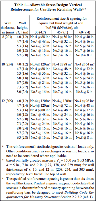
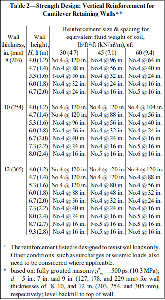
Recommended stem designs for reinforced cantilever retaining walls with no surcharge are contained in Tables 1 and 2 for allowable stress design and strength design, respectively. These design methods are discussed in detail in ASD of Concrete Masonry (2012 IBC & 2011 MSJC), TEK 14-07C, and Strength Design Provisions for Concrete Masonry, TEK 14-04B (refs. 5, 6).

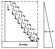
Figure 1 illustrates typical cantilever retaining wall detailing requirements.

DESIGN EXAMPLE

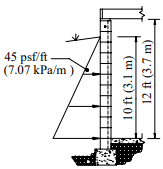
The following design example briefly illustrates some of the basic steps used in the allowable stress design of a reinforced concrete masonry cantilever retaining wall.

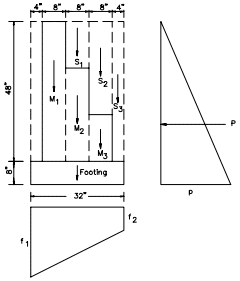
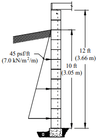
Example: Design the reinforced concrete masonry cantilever retaining wall shown in Figure 2. Assume level backfill, no surcharge or seismic loading, active earth pressure and masonry laid in running bond. The coefficient of friction between the footing and foundation soil, k1, is 0.25, and the allowable soil bearing pressure is 2,000 psf (95.8 kPa) (ref. 7).

a. Design criteria:

Wall thickness = 12 in. (305 mm)
f’m = 1,500 psi (10.3 MPa)

Assumed weights:
Reinforced masonry: 130 pcf (2,082 kg/m³) (solid grout to increase overturning and sliding resistance)
Reinforced concrete: 150 pcf (2,402 kg/m³)

Required factors of safety (ref. 7)
F.S. (overturning) = 1.5
F.S. (sliding) = 1.5

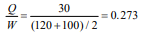
b. Rankine active earth pressure

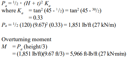
c. Resisting moment (about toe of footing)

Component weights:
masonry: (0.97)(8.67 ft)(130 pcf) = 1,093 lb/ft (16 kN/m)
earth: (2.69)(8.67 ft)(120 pcf) = 2,799 lb/ft (41 kN/m)
footing: (1.0)(5.33 ft)(150 pcf) = 800 lb/ft (12 kN/m)

Weight (lb/ft)XArm (ft)=Moment (ft-lb/ft)
masonry:1,093X2.67=2,918
earth:2,799X3.98=11,140
footing:800X2.67=2,136
4,69216,194
Total resisting moment16,194 ft-lb/ft
Overturning moment– 5,966 ft-lb/ft
10,228 ft-lb/ft (45.5 kN m/m)

d. Check factors of safety (F.S.)

F.S. (overturning)
= total resisting moment about toe/overturning moment
= 14,670/5,966
= 2.4 > 1.5 O.K.

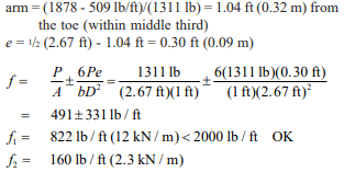
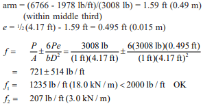
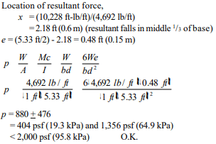
e. Pressure on footing

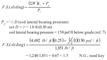
f. Determine size of key

Passive lateral soil resistance = 150 psf/ft of depth and may be increased 150 psf for each additional foot of depth to a maximum of 15 times the designated value (ref. 7). The average soil pressure under the footing is: ½ (1,356 + 404) = 880 psf (42.1 kPa).

Equivalent soil depth: 880 psf/120 pcf = 7.33 ft (2.23 m)

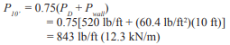
Pp = (150 psf/ft)(7.33 ft) = 1,100 psf (52.7 kPa)

For F.S. (sliding) = 1.5, the required total passive soil resistance is: 1.5(1,851 lb/ft) = 2,776 lb/ft (41 kN/m)

The shear key must provide for this value minus the frictional resistance: 2,776 – 1,248 = 1,528 lb/ft (22 kN/m).

Depth of shear key = (1,528 lb/ft)/(1,100 psf) = 1.39 ft (0.42 m), try 1.33 ft (0.41 m).

At 1.33 ft, lateral resistance = (1,100 psf) + (150 psf/ft)(1.33 ft) = 1,300 lb/ft (19 kN/m)
Depth = (1,528 lb/ft)/[½ (1,100 + 1,300)] = 1.27 ft (0.39 m) < 1.33 ft (0.41 m) O.K.

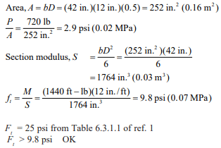
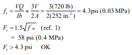
g. Design of masonry

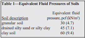
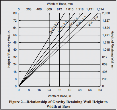
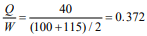
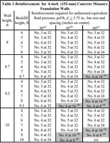
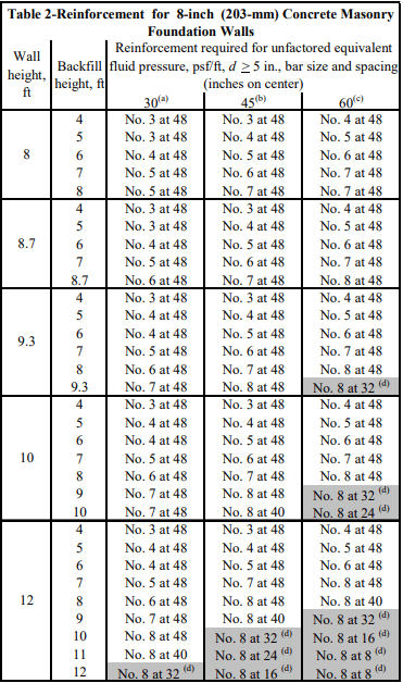
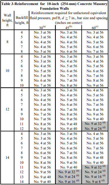
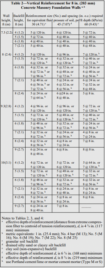
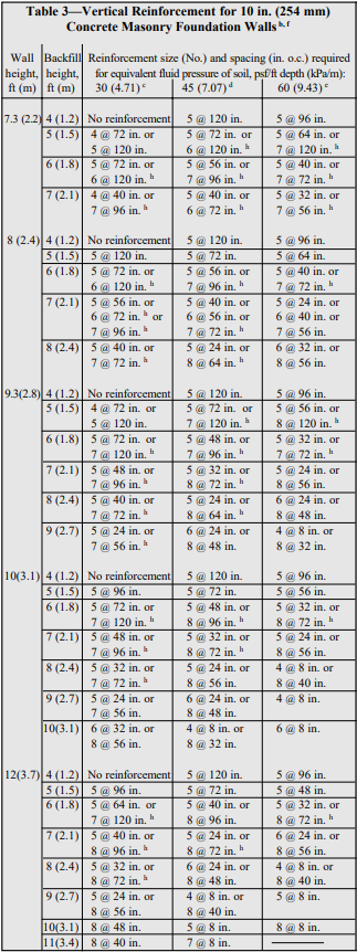
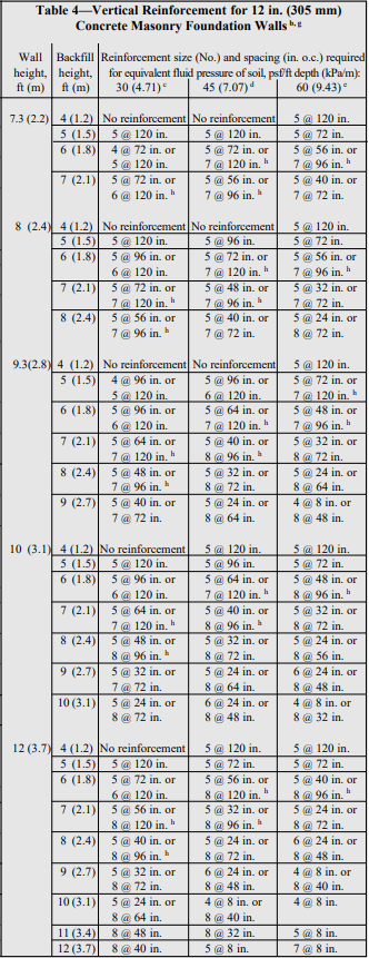
Tables 1 and 2 can be used to estimate the required reinforcing steel based on the equivalent fluid weight of soil, wall thickness, and wall height. For this example, the equivalent fluid weight = (Ka)(º) = 0.33 x 120 = 40 pcf (6.2 kN/m³).

Using allowable stress design (Table 1) and the conservative equivalent fluid weight of soil of 45 pcf (7.1 kN/m³), this wall requires No. 6 bars at 16 in. o.c. (M #19 at 406 mm o.c.). Using strength design (Table 2), this wall requires No. 5 bars at 16 in. o.c. (M #16 at 406 mm o.c.).

h. Design of footing

The design of the reinforced concrete footing and key should conform to American Concrete Institute requirements. For guidance, see ACI Standard 318 (ref. 2) or reinforced concrete design handbooks.

CONSTRUCTION

Materials and construction practices should comply with applicable requirements of Specification for Masonry Structures (ref. 4), or applicable local codes.

Footings should be placed on firm undisturbed soil, or on adequately compacted fill material. In areas exposed to freezing temperatures, the base of the footing should be placed below the frost line. Backfilling against retaining walls should not be permitted until the masonry has achieved sufficient strength or the wall has been adequately braced. During backfilling, heavy equipment should not approach closer to the top of the wall than a distance equal to the height of the wall. Ideally, backfill should be placed in 12 to 24 in. (305 to 610 mm) lifts, with each lift being compacted by a hand tamper. During construction, the soil and drainage layer, if provided, also needs to be protected from saturation and erosion.

Provisions must be made to prevent the accumulation of water behind the face of the wall and to reduce the possible effects of frost action. Where heavy prolonged rains are anticipated, a continuous longitudinal drain along the back of the wall may be used in addition to through-wall drains.

Climate, soil conditions, exposure and type of construction determine the need for waterproofing the back face of retaining walls. Waterproofing should be considered: in areas subject to severe frost action; in areas of heavy rainfall; and when the backfill material is relatively impermeable. The use of integral and post-applied water repellents is also recommended. The top of masonry retaining walls should be capped or otherwise protected to prevent water entry.

REFERENCES

  1. Building Code Requirements for Masonry Structures, ACI 530-05/ASCE 5-05/TMS 402-05. Reported by the Masonry Standards Joint Committee, 2005.
  2. Building Code Requirements for Structural Concrete and Commentary, ACI 318-02. Detroit, MI: American Concrete Institute, 2002.
  3. Das, B. M. Principles of Foundation Engineering. Boston, MA: PWS Publishers, 1984.
  4. Specification for Masonry Structures, ACI 530.1-05/ASCE 6-05/TMS 602-05. Reported by the Masonry Standards Joint Committee, 2005.
  5. ASD of Concrete Masonry (2012 IBC & 2011 MSJC), TEK 14-07C, Concrete Masonry & Hardscapes Association, 2004.
  6. Strength Design Provisions for Concrete Masonry, TEK 14-04B, Concrete Masonry & Hardscapes Association, 2008.
  7. 2003 International Building Code. International Code Council, 2003.

NOTATIONS

a     length of footing toe, in. (mm)
B     width of footing, ft (m)
d     distance from extreme compression fiber to centroid of tension reinforcement, in. (mm)
e       eccentricity, in. (mm)
F.S.  factor of safety
f’m     specified compressive strength of masonry, psi (MPa)
H       total height of backfill, ft (m)
I         moment of inertia, ft4 (m4)
Ka      active earth pressure coefficient
k1       coefficient of friction between footing and foundation soil
M       maximum moment in section under consideration, ft-lb/ft (kN⋅m/m)
Pa       resultant lateral load due to soil, lb/ft (kN/m)
Pp       passive earth pressure, lb/ft (N/m)
p         pressure on footing, psf (MPa)
T         thickness of wall, in. (mm)
t          thickness of footing, in. (mm)
W       vertical load, lb/ft (N/m)
x         location of resultant force, ft (m)
º         density of soil, pcf (kg/m³)
¤         angle of internal friction of soil, degreesDisclaimer: Although care has been taken to ensure the enclosed information is as accurate and complete as possible, NCMA does not assume responsibility for errors or omissions resulting from the use of this TEK.

Concrete Masonry Gravity Retaining Walls

INTRODUCTION

Retaining walls support soil and other materials laterally. That is, retaining walls “retain” earth, keeping it from sliding. Retaining walls must resist overturning and sliding, and the pressure under the toe (front bottom edge of footing) should not exceed the bearing capacity of the soil. Finally, the wall must be strong enough to prevent failure at any point in its height due to the pressure of the retained material. Concrete masonry retaining walls meet these requirements admirably.

Three different types of concrete masonry retaining walls are illustrated in Figure 1. They are the simple unreinforced vertical face gravity retaining wall, the steel reinforced cantilever retaining wall, and the segmental retaining wall. This TEK addresses unreinforced gravity retaining walls only. Each of these retaining wall systems has its advantages, and the choice may depend on a number of factors including aesthetics, constructibility, cost, and suitability for a particular project. The gravity wall is much simpler in design and construction, and can be an effective choice for smaller projects. It is thicker at the base than cantilever and segmental walls, and hence could cost more to construct on larger projects. Gravity retaining walls resist sliding by means of their large mass, whereas cantilever retaining walls are designed to resist sliding by using reinforcement. Because of their large mass, gravity retaining walls may not be appropriate for use on soils with low bearing capacities.

An engineer who is familiar with local conditions can assist in the choice of retain ing wall type. Where especially unfavorable soil conditions occur or where piling is required under a retaining wall, the assistance of an engineer is essential for design and construction.

DESIGN

The primary force acting on a retaining wall is the pressure exerted by the retained material at the back of the wall and on the heel of the footing. The magnitude and direction of this pressure depends on the height and shape of the surface and on the nature and properties of the backfill. One common method of estimating backfill pressure is the equivalent fluid pressure method. In this method, it is assumed that the retained earth will act as a fluid in exerting pressure on the wall. Assumed equivalent fluid pressures vary with the type of soil. Representative soil types with their equivalent fluid pressures are shown in Table 1.

Since the stability of the gravity type retaining wall depends mainly on its weight, the thickness required at its base will increase with height of backfill, or wall height. Uplift pressure at the back of the wall (the heel) is avoided by designing the gravity retaining wall thick enough at the base so that the resultant of all forces (overturning force and vertical loads) falls within a zone called the kern, which is the middle one third of the base. The eccentricity of the resultant force is equal to or less than one-sixth of the base width. When the eccentricity, e, is equal to one-sixth the base width exactly, the maximum footing pressure on the soil at the front edge of the base (toe) will be twice the average pressure on the soil.

The horizontal force of the retained material causes the overturning moment on the gravity retaining wall. For a given wall height, the required thickness at the base will depend not only on height, but also on the magnitude of the equivalent fluid pressure of the retained soil. The two forces act in opposition; the horizontal force tends to overturn the wall, while the vertical forces tend to stabilize it via gravity. The ratio of wall height to base width will vary with the ratio of vertical pressure to horizontal pressure. More properly, the relationship between thickness of base and wall height can be expressed:

where:
H = height of gravity retaining wall, in. (mm)
L = width of gravity retaining wall at base, in. (mm)
Q = equivalent fluid pressure of retained material acting horizontally as overturning moment, pcf (kg/m³)
W = average weight of masonry, soil and other material acting vertically to retain soil, pcf (kg/m³)

This relationship between wall height and base width for gravity retaining walls is shown in Figure 2 for different ratios of horizontal to vertical unit loads. The relationship shown in Figure 2 is employed in the selection of dimensions for gravity retaining walls up to eight ft (1.8 to 2.4 m) high.

Having selected the height-base proportions from Figure 2, the trial design is analyzed for safety against overturning and sliding, bearing pressure on the soil, and flexural and shear stress in the wall.

CONSTRUCTION AND MATERIALS

Each course of the retaining wall should be constructed with full-size concrete masonry units, with an overlapping bond pattern between courses, as shown in Figure 3.

Hollow or solid concrete masonry units used in gravity retaining walls should meet the requirements of ASTM C 90 (ref. 2) and preferably have an oven-dry density of 125 lb/ft³ (2002 kg/m³) or more. Cores of hollow units are typically filled to increase the weight of the wall. The fill should be granular in areas subject to freezing. Bond is important to ensure sufficient shear resistance to withstand the pressure exerted by the retained earth. Type M or S mortars complying to ASTM C 270 (ref. 3) are recommended.

Concrete footings should be placed on firm undisturbed soil. In areas where freezing is expected, the base of the footing should be placed below the frost line. If the soil under the footing consists of soft or silty clay, it is usually advisable to place 4 to 6 in. (102 to 152 mm) of well compacted sand or gravel under the footing before pouring the concrete. It is usually not necessary to reinforce the footing.

If heavy equipment is employed for backfilling, it should not be allowed to approach closer to the top of the wall than a distance equal to the wall height. Care should also be taken to avoid large impact forces on the wall as could occur by a large mass of moving earth.

Provision should be made to pre vent water accumulation behind the retaining wall. Accumulated water causes increased pressure, seep age, and in areas subject to frost action, an expansive force of considerable magnitude near the top of the wall. In most instances, weep holes located at 5 to 10 foot (1.5 to 3 m) spacing along the base of the wall are sufficient.

DESIGN EXAMPLES

  1. 4-foot (1.2 m) high gravity retaining wall
    equivalent fluid pressure of soil = 30 pcf (4.7 kN/m³)
    soil weight = 100 pcf (15.7 kN/m³)
    soil friction coefficient = 0.55
    soil bearing capacity = 2000 lb/ft² (0.096 MPa)
    100% solid concrete masonry units, 120 pcf (18.9 kN/m³)
    concrete footing, 150 pcf (23.6 kN/m³)

First, determine the width of the wall base:

From Figure 2, the base of the wall is 24 in. (610 mm), which can be accomplished using three 8-inch (203 mm) block. Note that the footing weight was not included in the calculation of average unit weight of the materials acting vertically, so that the width determined from Figure 2 would be the width of the masonry wall at its base.

Determine overturning moment:
pressure at the base of the wall, p = total soil height x equivalent fluid pressure of soil
p = (4.67 ft)(30 pcf) = 140 lb/ft² (6703 Pa)
resultant pressure, P = ½ (p)(total soil height)
P = ½ (140 lb/ft²)(4.67 ft) = 327 lb/ft (4.8 kN/m)

Determine resisting moment (about the toe):
First, determine the weight of each element, then determine the resisting moment of each weight, then sum the resisting moments to determine the total resisting moment.


Element:Weight 
S1(0.67 ft)(1.33 ft)(100 pcf)= 89 lb (396 N)
S2(0.67 ft)(2.67 ft)(100 pcf)= 179 lb (796 N)
S3(0.33 ft)(4.0 ft)(100 pcf)= 132 lb (587 N)
M1(0.67 ft)(4.0 ft)(120 pcf)= 322 lb (1432 N)
M2(0.67 ft)(2.67 ft)(120 pcf)= 214 lb (952 N)
M3(0.67 ft)(1.33 ft)(120 pcf)= 107 lb (476 N)
F(2.67 ft)(0.67 ft)(150 pcf)= 268 lb (1192 N)


Element:Weight, lb (N) xArm, ft (m) =Moment, ft-lb (N-m)
S189 (396)1.33 (0.41)118.5 (161)
S2179 (796)2.00 (0.61)357.8 (485)
S3132 (587)2.50 (0.76)330.0 (447)
M1322 (1432)0.67 (0.20)215.5 (292)
M2214 (952)1.33 (0.41)285.5 (387)
M3107 (476)2.00 (0.61)213.9 (290)
F268 (1192)1.33 (0.41)356.4 (483)
Total1311 (5832) 1878 (2546)


Determine the overturning moment about the base, M:
M = (P)( x total height of soil)
M = (327 lb/ft)(⅓ x 4.67 ft) = 509 ft-lb/ft (2.28 kN-m/m)

Check safety factors:
overturning moment safety factor = 1878/509 = 3.7
3.7 > 2 OK
sliding safety factor = (1311 lb)(0.55)/(327 lb/ft) = 2.2
2.2 > 1.5 OK

Check pressure on soil:

Since the concrete masonry used in this example is assumed solid or fully grouted, the calculations do not include a check of shear stresses and flexural stresses in the wall. Flexural and shear stresses are checked in the second design example, and it is seen that the magnitudes are very low. Flexural and shear stresses in gravity retaining walls will almost always be of minor importance.

  1. 6-foot (1.8 m) high gravity retaining wall
    equivalent fluid pressure of soil = 40 pcf (7.1 kN/m³)
    soil weight = 100 pcf (15.7 kN/m³)
    soil friction coefficient = 0.55
    soil bearing capacity = 2000 lb/ft² (0.096 MPa)
    hollow concrete masonry units, 130 pcf (20.4 kN/m³), units will be filled with sand, resulting in a combined weight of 115 pcf (18.1 kN/m³)
    f’m = 1500 psi (10.3 MPa)

Type S portland cement-lime mortar concrete footing, 150 pcf (23.6 kN/m³)

First, determine the width of the wall base:

From Figure 2, try a base width of 42 in. (1067 mm), with a footing width of 50 in. (1270 mm)

Determine overturning moment:
p = (6.67 ft)(40 pcf) = 267 lb/ft² (0.013 MPa)
P = ½ (267 lb/ft²)(6.67 ft) = 890 lb/ft (13 kN/m)
M = (890 lb/ft)(⅓ x 6.67 ft) = 1978 ft-lb/ft (8.81 kN-m/m)

Element:Weight, lb (N) xArm, ft (m) =Moment, ft-lb (N-m)
S122 (98)1.50 (0.46)33 (45)
S244 (196)1.83 (0.56)80 (108)
S366 (294)2.17 (0.66)143 (194)
S488 (391)2.50 (0.76)220 (298)
S5110 (489)2.83 (0.86)311 (422)
S6132 (587)3.17 (0.97)418 (566)
S7154 (685)3.50 (1.07)539 (731)
S8176 (783)3.83 (1.17)674 (914)
S9198 (881)4.17 (1.27)826 (1120)
M1690 (3070)0.83 (0.25)575 (780)
M2202 (899)1.50 (0.46)303 (411)
M3177 (787)1.83 (0.56)325 (441)
M4152 (676)2.17 (0.66)329 (446)
M5126 (560)2.50 (0.76)316 (428)
M6101 (449)2.83 (0.86)287 (389)
M776 (338)3.17 (0.97)241 (327)
M850 (222)3.50 (1.07)177 (240)
M925 (111)3.83 (1.17)97 (132)
F419 (1864)2.08 (0.63)872 (1182)
Total3008 (13,380)6766 (9173)


Check safety factors:
overturning moment safety factor = 6766/1978 = 3.4
3.4 > 2 OK
sliding safety factor = (3008 lb)(0.55)/(890 lb/ft) = 1.9
1.9 > 1.5 OK

Check pressure on soil:
location of P and eccentricity, e:

Check flexural stresses:
At 6 ft (1.8 m) depth:
P = ½ (6 ft)(40 pcf)(6 ft) = 720 lb (3203 N)
M = (720 lb)(⅓ x 6 ft) = 1440 ft-lb (1952 N-m)

Assume mortar bed is 50% of gross area:

Check shear stresses:

REFERENCES

  1. Building Code Requirements for Masonry Structures, ACI 530-95/ASCE 5-95/TMS 402-95. Reported by the Masonry Standards Joint Committee, 1995.
  2. Standard Specification for Load-Bearing Concrete Masonry Units, ASTM C 90-94. American Society for Testing and Materials, 1994.
  3. Standard Specification for Mortar for Unit Masonry, ASTM C 270-92a. American Society for Testing and Materials, 1992.

Strength Design of Reinforced Concrete Masonry Foundation Walls

INTRODUCTION

Although concrete masonry foundation walls can be constructed without reinforcing steel, reinforcement may be required for walls supporting large soil backfill loads. The strength design provisions found in Chapter 3 of Building Code Requirements for Masonry Structures (ref. 1) typically provides increased economy over the allowable stress design method, as thinner walls or larger reinforcing bar spacings often result from a strength design analysis. Strength design criteria are presented in detail in TEK 14-04B, Strength Design Provisions for Concrete Masonry (ref. 2).

DESIGN LOADS

Soil imparts lateral loads on foundation walls. The load is assumed to increase linearly with depth, resulting in a triangular load distribution on the wall. This lateral soil load is expressed as an equivalent fluid pressure, with units of pounds per square foot per foot of depth (kN/m²/m). For strength design analysis, this lateral soil pressure is increased by multiplying by a load factor, which provides a factor of safety against overload conditions. The maximum moment on the wall depends on the total wall height, the soil backfill height, the wall support conditions, the factored soil load, the existence of any surcharges on the soil and the presence of saturated soils.

Foundation walls also provide support for the structure above the foundation, transferring vertical loads to the footing. Vertical compression counteracts flexural tension, increasing the wall’s resistance to flexure. In low-rise construction, these vertical loads are typically small in relation to the compressive strength of the concrete masonry. Vertical load effects are not addressed in this TEK.

DESIGN TABLES

Tables 1 through 4 present reinforcement schedules for 6, 8, 10 and 12-in. (152, 203, 254 and 305-mm) walls, respectively. Additional reinforcement alternatives may be appropriate, and can be verified with an engineering analysis. Walls from 8 to 16 ft (2.4 to 4.9 m) high and soil pressures of 30, 45 and 60 psf/ft (4.7, 7.0, and 9.4 kN/m²/m) are included.

The effective reinforcement depth, d, assumed for the analyses are practical values, taking into account variations in face shell thickness, a range of reinforcing bar sizes, minimum required grout cover and construction tolerances for placing the reinforcement.

The following assumptions also apply to the values in Tables 1 through 4:

  1. there are no surcharges on the soil adjacent to the wall,
  2. there are negligible axial loads on the wall,
  3. the wall is simply supported at top and bottom,
  4. the wall is grouted at cells containing reinforcement (although solid grouting is acceptable),
  5. section properties are based on minimum face shell and web thickness requirements of ASTM C 90 (ref. 3),
  6. the specified compressive strength of masonry, f’m, is 1500 psi (10.3 MPa),
  7. Grade 60 (413 MPa) reinforcement,
  8. reinforcement requirements listed account for a soil load factor of 1.6 (ref. 6),
  9. the maximum width of the compression zone is limited to six times the wall thickness, or a 72 in. (1,829 mm) vertical bar spacing, whichever is smaller,
  10. reinforcing steel is placed toward the tension (interior) face of the wall (as shown in Figure 1), and
  11. the soil is well drained to preclude the presence of saturated soil.

DESIGN EXAMPLE

Wall: 12-in. (305 mm) thick concrete masonry foundation wall, 12 ft (3.66 m) high

Soil: equivalent fluid pressure is 45 psf/ft (7.0 kN/m²/m) (excluding soil load factors), 10 ft (3.05 m) backfill height

Using Table 4, the wall can be adequately reinforced using No. 9 bars at 72 in. o.c. (M# 29 at 1,829 mm).

CONSTRUCTION ISSUES

This section discusses those issues which directly relate to structural design assumptions. See TEK 03-11, Concrete Masonry Basement Wall Construction and TEK 05-03A, Concrete Masonry Foundation Wall Details (refs. 4, 5) for more complete information on building concrete masonry foundation walls.

Figure 1 illustrates wall support conditions, drainage and protection from water. Before backfilling, the floor diaphragm must be in place, or the wall must be properly braced to resist the soil load. Ideally, the backfill should be free-draining granular material, free from expansive soils or other deleterious materials.

The assumption that there are no surcharges on the soil means that heavy equipment should not be operated directly adjacent to any basement wall system. In addition, the backfill materials should be placed and compacted in several lifts. Care should be taken when placing backfill materials to prevent damaging the drainage, waterproofing or exterior insulation systems.

REFERENCES

  1. Building Code Requirements for Masonry Structures, ACI 530-02/ASCE 5-02/TMS 402-02. Reported by the Masonry Standards Joint Committee, 2002.
  2. Strength Design Provisions for Concrete Masonry, TEK 14-04B, Concrete Masonry & Hardscapes Association, 2008.
  3. Standard Specification for Loadbearing Concrete Masonry Units, ASTM C 90-03. ASTM International, 2003.
  4. Concrete Masonry Basement Wall Construction, TEK 0311, Concrete Masonry & Hardscapes Association, 2001.
  5. Concrete Masonry Foundation Wall Details, TEK 05-03A, Concrete Masonry & Hardscapes Association, 2003.
  6. Minimum Design Loads for Buildings and Other Structures, ASCE 7-02. American Society of Civil Engineers, 2002.


Allowable Stress Design of Concrete Masonry Foundation Walls

INTRODUCTION

Basements provide: economical living, working and storage areas; convenient spaces for mechanical equipment; safe havens during tornadoes and other violent storms; and easy access to plumbing and ductwork. Concrete masonry is well suited to basement and foundation wall construction due to its inherent durability, compressive strength, economy, and resistance to fire, termites, and noise.

Traditionally, residential basement walls have been constructed of plain (unreinforced) concrete masonry, often designed empirically. Walls over 8 ft (2.4 m) high or with larger soil loads are typically designed using reinforced concrete masonry or using design tables included in building codes such as the International Building Code (ref. 4).

DESIGN LOADS

Soil imparts a lateral load on foundation walls. For design, the load is traditionally assumed to increase linearly with depth resulting in a triangular load distribution. This lateral soil load is expressed as an equivalent fluid pressure, with units of pounds per square foot per foot of depth (kPa/m). The maximum force on the wall depends on the total wall height, soil backfill height, wall support conditions, soil type, and the existence of any soil surcharges. For design, foundation walls are typically assumed to act as simple vertical beams laterally supported at the top and bottom.

Foundation walls also provide support for the structure above, transferring vertical loads to the footing. When foundations span vertically, this vertical compression counteracts flexural tension, increasing the wall’s resistance to flexure. In low-rise construction, these vertical loads are typically small in relation to the compressive strength of concrete masonry. Further, if the wall spans horizontally, vertical compression does not offset the flexural tension. Vertical load effects are not included in the tables and design example presented in this TEK (references 2 and 3 include vertical load effects).

EMPIRICAL DESIGN

The empirical design method uses historical experience to proportion and size masonry elements. Empirical design is often used to design concrete masonry foundation walls due to its simplicity and history of successful performance.

Table 1 lists the allowable backfill heights for 8, 10 and 12-inch (203, 254 and 305 mm) concrete masonry foundation walls. Table 1 may be used for foundation walls up to 8 feet (2.4 m) high under the following conditions (ref. 1):

  1. terrain surrounding the foundation wall is graded to drain surface water away from foundation walls,
  2. backfill is drained to remove ground water away from foundation walls,
  3. tops of foundation walls are laterally supported prior to backfilling,
  4. the length of foundation walls between perpendicular masonry walls or pilasters is a maximum of 3 times the foundation wall height,
  5. the backfill is granular and soil conditions in the area are non-expansive,
  6. masonry is laid in running bond using Type M or S mortar, and
  7. units meet the requirements of ASTM C 90 (ref. 6).

Where these conditions cannot be met, the wall must be engineered using either an allowable stress design (see following section) or strength design procedure (see ref. 5).

WALL DESIGN

Tables 2 through 4 of this TEK have been rationally designed in accordance with the allowable stress design provisions of Building Code Requirements for Masonry Structures (ref. 1) and therefore meet the requirements of the International Building Code even though the latter limits reinforcment spacing to 72 in. (1829 mm) when using their tables. Additional reinforcement alternatives may be appropriate and can be verified with an engineering analysis.

Tables 2, 3 and 4 list reinforcement options for 8, 10 and 12-in. (203, 254 and 305-mm) thick walls, respectively. The effective depths of reinforcement, d, (see Table notes) used are practical values, taking into account variations in face shell thickness, a range of bar sizes, minimum required grout cover, and construction tolerances for placing the reinforcing bars.

Tables 2 through 4 are based on the following:

  1. no surcharges on the soil adjacent to the wall and no hydrostatic pressure,
  2. negligible axial loads on the wall,
  3. wall is simply supported at top and bottom,
  4. wall is grouted only at reinforced cells,
  5. section properties are based on minimum face shell and web thicknesses in ASTM C 90 (ref. 6),
  6. specified compressive strength of masonry, f’m, is 1,500 psi (10.3 MPa),
  7. reinforcement yield strength, fy, is 60,000 psi (414 MPa),
  8. modulus of elasticity of masonry, Em, is 1,350,000 psi (9,308 MPa),
  9. modulus of elasticity of steel, Es, is 29,000,000 psi (200,000 MPa),
  10. maximum width of compression zone is six times the wall thickness (where reinforcement spacing exceeds this distance, the ability of the plain masonry outside the compression zone to distribute loads horizontally to the reinforced section was verified assuming two-way plate action),
  11. allowable tensile stress in reinforcement, Fs, is 24,000 psi (165 MPa),
  12. allowable compressive stress in masonry, Fb, is f’m (500 psi, 3.4 MPa),
  13. grout complies with ASTM C 476 (2,000 psi (14 MPa) if property spec is used) (ref. 7), and
  14. masonry is laid in running bond using Type M or S mortar and face shell mortar bedding.

DESIGN EXAMPLE

Wall: 12-inch (305 mm) thick, 12 feet (3.7 m) high.

Loads: equivalent fluid pressure of soil is 45 pcf (7.07 kPa/ m), 10 foot (3.1 m) backfill height. No axial, seismic, or other loads.

Using Table 4, #8 bars at 40 in. (M 25 at 1016 mm) o.c. are sufficient.

CONSTRUCTION ISSUES

This section is not a complete construction guide, but rather discusses those issues directly related to structural design assumptions. Figures 1 and 2 illustrate typical wall support conditions, drainage, and water protection.

Before backfilling, the floor diaphragm must be in place or the wall must be properly braced to resist the soil load. In addition to the absence of additional dead or live loads following construction, the assumption that there are no surcharges on the soil also means that heavy equipment should not be operated close to basement wall systems that are not designed to carry the additional load. In addition, the backfill materials should be placed and compacted in several lifts, taking care to prevent wall damage. Care should also be taken to prevent damaging the drainage, waterproofing, or exterior insulation systems, if present.

REFERENCES

  1. Building Code Requirements for Masonry Structures, ACI 530-99/ASCE 5-99/TMS 402-99. Reported by the Masonry Standards Joint Committee, 1999.
  2. International Building Code. International Code Council, 2000.
  3. Strength Design of Reinforced CM Foundation Walls, TEK 15-02B, Concrete Masonry & Hardscapes Association, 2004.
  4. Standard Specification for Loadbearing Concrete Masonry Units, ASTM C 90-01. American Society for Testing and Materials, 2001.
  5. Standard Specification for Grout Masonry, ASTM C476- 01. American Society for Testing and Materials, 2001.

ASD Tables for Reinforced Concrete Masonry Walls Based on the 2012 IBC & 2011 MSJC

INTRODUCTION

The combination of concrete masonry and steel reinforcement provides a strong structural system capable of resisting large compressive and flexural loads. Reinforced masonry structures have significantly higher flexural strength and ductility than similarly configured unreinforced structures and provide greater reliability in terms of expected load carrying capacity at failure.

Concrete masonry elements can be designed using several methods in accordance with the International Building Code (IBC, ref. 1) and, by reference, Building Code Requirements for Masonry Structures (MSJC Code, ref. 2): allowable stress design, strength design, direct design, empirical design, or prestressed masonry. The design tables in this TEK are based on allowable stress design provisions.

The content presented in this edition of TEK 14-19B is based on the requirements of the 2012 IBC (ref. 1a), which in turn references the 2011 edition of the MSJC Code (ref. 2a). For designs based on the 2006 or 2009 IBC (refs. 1b, 1c), which reference the 2005 and 2008 MSJC (refs. 2b, 3c), respectively, the reader is referred to TEK 14-19B (ref. 3).

Significant changes were made to the allowable stress design (ASD) method between the 2009 and 2012 editions of the IBC. These are described in detail in TEK 14-07C, ASD of Concrete Masonry (2012 IBC & 2011 MSJC) (ref. 4), along with a detailed presentation of all of the allowable stress design provisions of the 2012 IBC.

LOAD TABLES

Tables 1 and 2 list the maximum bending moments and shears, respectively, imposed on walls simply supported at the top and bottom and subjected to uniform lateral loads with no applied axial loads.

WALL CAPACITY TABLES

Tables 3, 4, 5 and 6 contain the maximum bending moments and shear loads that can be sustained by 8-, 10-, 12-, and 16-in. (203-, 254-, 305-, 406 mm) walls, respectively, without exceeding the allowable stresses defined in the 2012 IBC and 2011 MSJC (refs. 1a, 2a). These wall strengths can be compared to the loads in Tables 1 and 2 to ensure the wall under consideration has sufficient design capacity to resist the applied load.

The values in Tables 3 through 6 are based on the following criteria:

  • Maximum allowable stresses:
  • f’m = 1500 psi (10.3 MPa)
  • Em  = 900f’m or 1,350,000 psi (9,310 MPa)
  • Es = 29,000,000 psi (200,000 MPa)
  • Type M or S mortar
  • running bond or bond beams at 48 in. (1,219 mm) max o.c.
  • reinforcement spacing does not exceed the wall height
  • only cores containing reinforcement are grouted.

Reinforcing Steel Location

Two sets of tables are presented for each wall thickness. Tables 3a, 4a, 5a and 6a list resisting moment and resisting shear values for walls with the reinforcing steel located in the center of the wall. Centered reinforcing bars are effective for providing tensile resistance for walls which may be loaded from either side, such as an above grade exterior wall which is likely to experience both wind pressure and suction.

Tables 3b, 4b, 5b and 6b list resisting moment and resisting shear values for walls with the reinforcing steel offset from the center.

Placing the reinforcement farther from the compression face of the masonry provides a larger effective depth of reinforcement, d, and correspondingly larger capacities. A single layer of off-center reinforcement can be used in situations where the wall is loaded from one side only, such as a basement wall with the reinforcement located towards the interior. For walls where loads can be in both directions (i.e. pressure or suction), two layers of reinforcement are used: one towards the wall exterior and one towards the interior to provide increased capacity under both loading conditions. In Tables 3b, 4b, 5b and 6b, the effective depth of reinforcement, d, is a practical value which takes into account construction tolerances and the reinforcing bar diameter.

Figure 1 illustrates the two steel location cases.


DESIGN EXAMPLE

A warehouse wall will span 34 ft (10.4 m) between the floor slab and roof diaphragm. The walls will be constructed using 12 in. (305 mm) concrete masonry units. What is the required reinforcing steel size and spacing to support a wind load of 20 psf (0.96 kPa)?

From interpolation of Tables 1 and 2, respectively, the wall must be able to resist:
M = 34,800 lb-in./ft (12.9 kN-m/m)
V = 340 lb/ft (4.96 kN/m)

Assuming the use of offset reinforcement, from Table 5b, No. 6 bars at 40 in. on center (M#19 at 1,016 mm) or No. 7 bars at 48 in. (M#22 at 1,219 mm) on center provides sufficient strength: for No. 6 bars at 40 in. o.c. (M#19 at 1,016 mm):
Mr = 35,686 lb-in./ft (13.3 kN-m/m) > M             OK
Vr = 2,299 lb/ft (33.5 kN/m) > V                           OK

for No. 7 bars at 48 in. (M#22 at 1,219 mm) :
Mr = 40,192 lb-in./ft (14.9 kN-m/m) > M              OK
Vr = 2,133 lb/ft (31.1 kN/m) > V                            OK

As discussed above, since wind loads can act in either direction, two bars must be provided in each cell when using off-center reinforcement—one close to each faceshell.

Alternatively, No. 6 bars at 24 in (M#19 at 610 mm) or No. 8 at 40 in (M#25 at 1,016 mm) could have been used in the center of the wall.

NOTATION

As   = area of nonprestressed longitudinal reinforcement, in.² (mm²)
b     = effective compressive width per bar, in. (mm)
d     = distance from extreme compression fiber to centroid of tension reinforcement, in. (mm)
Em  = modulus of elasticity of masonry in compression, psi (MPa)
Es   = modulus of elasticity of steel, psi (MPa)
Fb   = allowable compressive stress available to resist flexure only, psi (MPa)
Fs    = allowable tensile or compressive stress in reinforcement, psi (MPa)
Fv    = allowable shear stress, psi (MPa)
f’m   = specified compressive strength of masonry, psi (MPa)
M    = maximum calculated bending moment at section under consideration, in.-lb, (N-mm)
Mr   = flexural strength (resisting moment), in.-lb (N-mm)
V     = shear force, lb (N)
Vr    = shear capacity (resisting shear) of masonry, lb (N)

REFERENCES

  1. International Building Code. International Code Council.
    • 2012 Edition
    • 2009 Edition
    • 2006 Edition
  2. Building Code Requirements for Masonry Structures. Reported by the Masonry Standards Joint Committee.
    • 2011 Edition: TMS 402-11/ACI 530-11/ASCE 5-11
    • 2008 Edition: TMS 402-08 /ACI 530-08/ASCE 5-08
    • 2005 Edition: ACI 530-05/ASCE 5-05/TMS 402-05
  3. Allowable Stress Design Tables for Reinforced Concrete Masonry Walls, TEK 14-19B. Concrete Masonry & Hardscapes Association, 2009.
  4. Allowable Stress Design of Concrete Masonry Based on the 2012 IBC & 2011 MSJC, TEK 14-07C. Concrete Masonry & Hardscapes Association, 2011.


Concrete Masonry Fence Design

INTRODUCTION

Concrete masonry fences and garden walls are used to fulfill a host of functions, including privacy and screening, security and protection, ornamentation, sound insulation, shade and wind protection.

In addition, concrete masonry provides superior durability, design flexibility and economy. The wide range of masonry colors and textures can be used to complement adjacent architectural styles or blend with the natural landscape.

Because fences are subjected to outdoor exposure on both sides, selection of appropriate materials, proper structural design and quality workmanship are critical to maximize their durability and performance.

STRUCTURAL DESIGN

Masonry fences are generally designed using one of five methods:

  1. as cantilevered walls supported by continuous footings;
  2. as walls spanning between pilasters, that are, in turn, supported by a footing pad or caisson;
  3. as walls spanning between wall returns that are sufficient to support the wall;
  4. as curved walls with an arc-to-chord relationship that provides stability; or
  5. as a combination of the above methods.

This TEK covers cases (a) and (d) above, based on the provisions of the 2003 and 2006 editions of the International Building Code (refs. 1, 2). Although fences up to 6 ft (1,829 mm) high do not require a permit (refs. 1 and 2, Ch.1), this TEK provides guidance on design and construction recommen- dations. Fences designed as walls spanning between pilasters (case b) are covered in TEK 14-15B, Allowable Stress Design of Pier and Panel Highway Sound Barrier Walls (ref. 3). In addition, fences can be constructed by dry-stacking and surface bonding conventional concrete masonry units (see ref. 4), or by utilizing proprietary dry-stack fence systems.

CANTILEVERED FENCE STRUCTURAL DESIGN

Tables 1, 2 and 3 provide wall thickness and vertical reinforcement requirements for cantilevered walls for three lateral load cases: lateral load, w ≤ 15 psf (0.71 kPa), 15 < w ≤ 20 psf (0.95 kPa), and 20 < w ≤ 25 psf (1.19 kPa), respectively. For each table, footnote A describes the corresponding wind and seismic conditions corresponding to the lateral load, based on Minimum Design Loads for Buildings and Other Structures, ASCE 7 (ref. 5).

Assumptions used to develop Tables 1, 2 and 3 are:

  1. strength design method
  2. except as noted, designs comply with both the 2003 and 2006 International Building Code,
  3. running bond masonry,
  4. ASTM C 90 (ref. 6) concrete masonry units,
  5. specified compressive strength of masonry, f’m = 1,500 psi (10.3 MPa)
  6. ASTM C 270 (ref. 7) mortar as follows: Type N, S or M portland cement /lime mortar or Type S or M masonry cement mortar (note that neither Type N nor masonry cement mortar is permitted to be used in SDC D),
  7. ASTM C 476 (ref. 8) grout,
  8. Grade 60 reinforcing steel, reinforcement is centered in the masonry cell,
  9. depth from grade to top of footing is 18 in. for 4- and 6-ft (457 mm for 1.2- and 1.8-m) high fences; 24 in. for 8-ft (610 mm for 2.4-m) high fences, and
  10. reinforcement requirements assume a return corner at each fence end with a length at least equal to the exposed height. Where fence ends do not include a return, increase the design lateral load on the end of the fence (for a length equal to the exposed height) by 5 psf (34.5 kPa).

FOOTINGS

For cantilevered walls, the footing holds the wall in position and resists overturning and sliding due to lateral loads. Dowels typically extend up from the footing into the wall to transfer stresses and anchor the wall in place. Dowels should be at least equal in size and spacing to the vertical fence reinforcement. The required length of lap is determined according to the design procedure used and type of detail employed. For the design conditions listed here, the No. 4 (M#13) reinforcing bars require a minimum lap length of 15 in. (381 mm), and the No. 5 (M#16) bars require a minimum lap length of 21 in. (533 mm). Refer to TEK 12-06a, Splices, Development and Standard Hooks for Concrete Masonry (ref. 9) for detailed information on lap splice requirements.

Footings over 24 in. (610 mm) wide require transverse reinforcement (see footnotes to Table 4). For all footings, the hook should be at the bottom of the footing (3 in. (76 mm) clearance to the subgrade) in order to develop the strength of the bar at the top of the footing.

The footing designs listed in Table 4 conform with Building Code Requirements for Reinforced Concrete, ACI 318 (ref. 10). Note that concrete for footings placed in soils containing high sulfates are subject to additional requirements (refs. 1, 2).

SERPENTINE WALLS

Serpentine or “folded plate” wall designs add interesting and pleasing shapes to enhance the landscape. The returns or bends in these walls also provide additional lateral stability, allowing the walls to be built higher than if they were straight.

Serpentine and folded plate walls are designed using empirical design guidelines that historically have proven successful over many years of experience. The guidelines presented here are based on unreinforced concrete masonry for lateral loads up to 20 psf (0.95 kPa). See Table 2, footnote A for corresponding wind speeds and seismic design parameters.

Design guidelines are shown in Figure 2, and include:

  • wall radius should not exceed twice the height,
  • wall height should not exceed twice the width (or the depth of curvature, see Figure 2),
  • wall height should not exceed fifteen times the wall thickness, and
  • the free end(s) of the serpentine wall should have additional support such as a pilaster or a short-radius return.

A wooden template, cut to the specified radius, is helpful for periodically checking the curves for smoothness and uniformity. Refer to TEK 5-10A, Concrete Masonry Radial Wall Details (ref. 11) for detailed information on constructing curved walls using concrete masonry units.

CONSTRUCTION

All materials (units, mortar, grout and reinforcement) should comply with applicable ASTM standards. Additional material requirements are listed under the section Cantilevered Fence Structural Design, above.

To control shrinkage cracking, it is recommended that horizontal reinforcement be utilized and that control joints be placed in accordance with local practice. In some cases, when sufficient horizontal reinforcement is incorporated, control joints may not be necessary. Horizontal reinforcement may be either joint reinforcement or bond beams. See CMU-TEC-009-23, Crack Control Strategies for Concrete Masonry Construction (ref. 12) for detailed guidance.

In addition, horizontal reinforcement in the top course (or courses if joint reinforcement is used) is recommended to help tie the wall together. For fences, it is not structurally necessary to provide load transfer across control joints, although this can be accomplished by using methods described in CMU-TEC-009-23 if deemed necessary to help maintain the fence alignment.

Copings provide protection from water penetration and can also enhance the fence’s appearance. Various materials such as concrete brick, cast stone, brick and natural stone are suitable copings for concrete masonry fences. Copings should project at least ½ in. (13 mm) beyond the wall face on both sides to provide a drip edge, which will help keep dripping water off the face of the fence. In cases where aesthetics are a primary concern, the use of integral water repellents in the masonry units and mortar can also help minimize the potential formation of efflorescence.

REFERENCES

  1. 2003 International Building Code. International Code Council, 2003.
  2. 2006 International Building Code. International Code Council, 2006.
  3. Allowable Stress Design of Pier and Panel Highway Sound Barrier Walls, NCMA TEK 14-15B. Concrete Masonry & Hardscapes Association, 2004.
  4. Design and Construction of Dry-Stack Masonry Walls, TEK 14-22. National Concrete Masonry Association, 2003.
  5. Minimum Design Loads for Buildings and Other Structures, ASCE 7-02 and ASCE 7-05. American Society of Civil Engineers, 2002 and 2005.
  6. Standard Specification for Loadbearing Concrete Masonry Units, ASTM C 90-01a and C 90-03. ASTM International, Inc., 2001 and 2003.
  7. Standard Specification for Mortar for Unit Masonry, ASTM C 270-01a and C 270-04. ASTM International, Inc., 2001 and 2004.
  8. Standard Specification for Grout for Masonry, ASTM C 476-01 and C 476-02. ASTM International, Inc., 2001 and 2002.
  9. Splices, Development and Standard Hooks for Concrete Masonry, TEK 12-06A. Concrete Masonry & Hardscapes Association, 2007.
  10. Building Code Requirements for Structural Concrete, ACI 318-02 and ACI 318-05. Detroit, MI: American Concrete Institute, 2002 and 2005.
  11. Concrete Masonry Radial Wall Details, TEK 5-10A. Concrete Masonry & Hardscapes Association, 2006.
  12. Crack Control in Concrete Masonry Walls, TEK 10-1A. Concrete Masonry & Hardscapes Association, 2005.

Allowable Stress Design of Pier and Panel Highway Sound Barrier Walls

INTRODUCTION

Sound barrier walls are increasingly being used to reduce the impact of traffic noise on properties abutting major urban traffic routes. Because concrete masonry possesses many desirable features and properties—excellent sound resistance, low cost, design flexibility, structural capability and durability, it is an excellent material for the design and construction of highway sound barrier walls.

Aesthetics is also an important consideration. Noise barriers significantly impact a highway’s visual impression. Visual qualities of noise barriers include overall shape, end conditions, color, texture, plantings and artistic treatment.

The variety of concrete masonry surface textures, colors and patterns has led to its extensive use in sound barrier walls.

Various types of concrete masonry walls may be used for sound barriers. Pier and panel walls are relatively easy to build and are economical due to the reduced thickness of the walls and the intermittent pier foundations. In addition, the piers can be offset with respect to the panels to achieve desired aesthetic effects. Pier and panel walls are also easily adapted to varying terrain conditions and are often used in areas that have expansive soils.

This TEK presents information on the structural design of concrete masonry pier and panel sound barrier walls. Requirements and considerations for reduction of highway traffic noise are discussed in TEK 13-03A, Concrete Masonry Highway Noise Barriers (ref. 2).

DESIGN

Building Code Requirements for Masonry Structures, ACI 530/ASCE 5/TMS 402 (ref. 1) includes requirements for allowable stress design, strength design and prestressed approaches. The allowable stress design approach was used to develop the designs in this TEK. Allowable stresses were increased by one-third, as permitted for load combinations which include wind or seismic loads. Allowable Stress Design of Concrete Masonry, TEK 14-07C (ref. 4), describes the basic design approach.

Materials and Workmanship

Since concrete masonry sound barrier walls are subject to a wide range of load conditions, temperatures and moisture conditions, the selection of proper materials and proper workmanship is very important to ensure durability and satisfactory structural performance. Accordingly, it is recommended that materials (concrete masonry units, mortar, grout and reinforcement) comply with applicable requirements contained in Building Code Requirements for Masonry Structures (ref. 1).

Lateral Loads

Design lateral loads should be in accordance with those specified by local or state building and highway departments. If design lateral loads are not specified, it is recommended that they conform to those specified in Minimum Design Loads for Buildings and Other Structures, ASCE 7 (ref. 3). Wind and earthquake loads required in this standard are briefly described in the following paragraphs.

Design wind loads (F) on sound barrier walls may be determined as follows:

For the wall designs in this TEK, G is taken as 0.85 and C as 1.2. The minimum wind load specified in ASCE 7 is f 10 psf (479 Pa). For basic wind speeds of 85 mph (minimum), 90 mph, 100 mph, and 110 mph (53, 145, 161, and 177 kmph), the corresponding wind loads are listed in Table 1.

Earthquake loads (F ) on sound barrier walls may be p determined as follows, considering the wall system as a reinforced masonry non-building structure (ref. 3):

Seismic loads for a range of conditions are listed in Table 3.

Deflections

Deflection considerations typically govern wall design for long spans and taller walls with greater lateral loads. Deflections are imposed to limit the development of vertical flexure cracks within the wall panel and horizontal flexure cracks near the base of the pier. The design information presented in this TEK is based on a maximum allowable deflection of L/240, where L is the wall span between piers.

DESIGN TABLES

Design information for pier and panel walls is presented in Tables 4 through 7. Tables 4 and 5 provide horizontal reinforcing steel requirements for 6 in. and 8 in. (152 and 203 mm) panels, respectively. Horizontal reinforcement requirements can be met using either joint reinforcement or bond beams with reinforcing bars.

Table 6 provides pier size and reinforcement requirements for various lateral loads. Table 7 lists minimum sizes for pier foundations, as well as minimum embedment depths. These components of pier and panel walls are illustrated in Figure 1.

When pier and panels are used, walls are considered as deep beams, spanning horizontally between piers. Walls support their own weight, vertically, and also must resist lateral out-of-plane wind or seismic loads. The panels are built to be independent of the piers to accommodate masonry unit shrinkage and soil movement. For this design condition, wall reinforcement is located either in the horizontal bed joints or in bond beams. Wall reinforcement is based on maximum moments (M) and shears (V) in the wall panels, determined as follows:

The wall panels themselves are analyzed as simply supported beams, spanning from pier to pier.

In addition to the horizontal reinforcement, which transfers lateral loads to the piers, vertical reinforcement in the panels is required in Seismic Design Categories (SDC) C, D, E and F. Building Code Requirements for Masonry Structures (ref. 1) includes minimum prescriptive reinforcement as follows. In SDC C, vertical No. 4 (M #13) bars are located within 8 in. (203 mm) of the wall ends, and at 10 ft (3.0 m) on center along the length of the wall; minimum horizontal reinforcement requirements are satisfied by the primary reinforcement listed in Tables 4 and 5. In SDC D, E and F, vertical No. 4 (M #13) bars are located within 8 in. (203 mm) of the wall ends, and at 4 ft (1.22 m) on center along the length of the wall.

Table 6 shows pier size and vertical reinforcement requirements. Piers are designed as vertical cantilevers, not bonded with the walls, and pier reinforcement is based on maximum moment and shear, determined as follows:

Design assumptions for the pier and panel walls are given in Table 2. Note that allowable stresses were increased by one-third, as permitted for load combinations which include wind or seismic loads (ref. 1).

Requirements for concrete foundations supporting the concrete masonry piers are given in Table 7. These foundations can be constructed economically by drilling. The concrete foundation piers should contain vertical reinforcement (same as shown in Table 6) which should be properly lapped with vertical reinforcement in the concrete masonry piers. The embedment depths given in Table 7 are based on an allowable lateral passive soil pressure of 300 psf (14.4 kPa).

DESIGN EXAMPLE

A pier and panel highway sound barrier is to be designed using the following parameters:

  • 6 in. (152 mm) panel thickness
  • 10 ft (3.05 m) wall height
  • 14 ft (4.27 m) wall span
  • open terrain, stiff soil
  • basic wind speed is 90 mph (145 km/h)
  • SS = 0.25, SDC B

From Table 1, the design wind load is 14.1 psf (674 Pa) for a basic wind speed of 90 mph (145 km/h) and exposure C. Using Table 3, the design seismic load is determined to be 2.8 psf (0.13 kPa) for a 6 in. (152 mm) wall grouted at 48 in. (1219 mm), or less, on center, for SS = 0.25. Since the wind load is s greater, the wall will be designed for 14.1 psf (674 Pa).

Using Table 4, minimum horizontal panel reinforcement is either W1.7 (MW 11) joint reinforcement at 8 in. (203 mm) on center, or bond beams at 48 in. (1220 mm) on center reinforced with one No. 5 (M #16) bar. At the bottom, the panel requires a beam 16 in. (406 mm), or two courses, deep reinforced with one No. 5 (M # 16) bar (last column of Table 4). Because the wall is located in SDC B, vertical reinforcement is not required to meet prescriptive seismic requirements.

The minimum pier size is 16 x 18 in. (406 x 460 mm), reinforced with four No. 4 (M #13) bars, per Table 6. The pier foundation diameter is 18 in. (457 mm), and should be embedded at least 7.5 ft (2.29 m), per Table 7.

NOTATIONS

Af    = area normal to wind direction, ft² (m²)
Cf    = force coefficient (see ref. 3)
d     = distance from extreme compression fiber to centroid of tension reinforcement, in. (mm)
Em  = modulus of elasticity of masonry in compression, psi (MPa)
Es   = modulus of elasticity of steel, psi (MPa)
F     = design wind load, psf (Pa) (see ref. 3)
Fa   = acceleration-based site factor (at 0.3 second period) (see ref. 3)
Fm  = allowable masonry flexural compression stress, psi (Pa)
Fp   = seismic force, psf (Pa) (see ref. 3)
Fs   = allowable tensile or compressive stress in reinforcement, psi (MPa)
Fv   = allowable shear stress in masonry, psi (MPa)
f’m  = specified compressive strength of masonry, psi (MPa)
G    = gust effect factor (see ref. 3)
H    = wall height, ft (m)
I     = importance factor (see ref. 3)
Ip   = component importance factor (assume equal to 1.0 for sound barrier walls) (see ref. 3)
Kd  = wind directionality factor (see ref. 3)
Kz  = velocity pressure exposure coefficient (see ref. 3)
Kzt = hill and escarpment factor (see ref. 3)
L    = wall span, ft (m)
M   = maximum moment at the section under consideration, in.-lb (N-mm)
n    = ratio of elastic moduli, Es/Em
P    = applied lateral force, lb (N)
qz   = velocity pressure, psf (Pa) (see ref. 3)
= 0.00256K KzKztKdv²I
R    = response modification coefficient (see ref. 3)
Rp   = component response modification factor (equal to 3.0 for reinforced masonry non-building structures) (see ref. 3)
SDS = design short period spectral acceleration =⅔(FaSS), where SS varies from less than 0.25 to greater than 1.25, and Fa is dependent on SS and soil conditions at the site (see ref. 3)
Ss    = mapped maximum considered earthquake spectral response acceleration at short periods (see ref. 3)
V     = shear force, lb (N)
v      = basic wind speed, mph (km/h) (see ref. 3)
Wp   = weight of wall, psf (Pa)
w      = wind or seismic load, psf (Pa)

REFERENCES

  1. Building Code Requirements for Masonry Structures, ACI 530-02/ASCE 5-02/TMS 402-02. Reported by the Masonry Standards Joint Committee, 2002.
  2. Concrete Masonry Highway Noise Barriers, TEK 13-03A. Concrete Masonry & Hardscapes Association, 1999.
  3. Minimum Design Loads for Buildings and Other Structures, ASCE 7-02. American Society of Civil Engineers, 2002.
  4. Allowable Stress Design of Concrete Masonry, TEK 14-07C Concrete Masonry & Hardscapes Association, 2002.


Seismic Design Forces on Concrete Masonry Buildings

INTRODUCTION

This TEK describes procedures for determining loads to be used when designing masonry buildings to resist earthquakes. The information provided herein is an overview of methods for determining the design ground motion, calculating the building base shear and distributing earthquake forces to lateral load resisting elements. Also reviewed are the earthquake forces on masonry walls when they are loaded out-of-plane.

With the merging of the model building codes used in various regions of the United States into the International Building Code (IBC, ref. 1), the trend in structural design is to refer to nationally approved standards for various aspects of design. The 2003 IBC references Minimum Design Loads for Buildings and Other Structures, ASCE 7-02 (ref. 2) for determining design loads, including earthquake loads, on structures. This TEK does not address the seismic design of non-building masonry structures. TEK 14-18B (ref. 3) covers prescriptive seismic reinforcement requirements for masonry structures.

LOAD DETERMINATION

Determination of Design Ground Motion

The first step in obtaining the seismic design forces on masonry buildings is to determine the maximum earthquake intensity that the building must be designed to resist. Since the risk of earthquakes occurring and the intensity of ground shaking that may take place varies over the United States, the seismic design force varies with the building location. ASCE 7 addresses this issue by defining a design earthquake for all regions in the United States. The design earthquake is two thirds of the maximum considered earthquake, which is the ground motion that causes the most severe effects considered by the code. In most parts of the United States, the maximum considered earthquake corresponds to a ground motion with a 2 percent chance of being exceeded in fifty years. While more intense ground shaking may occur in these regions, it is generally considered uneconomical to design for such uncommon earthquakes. In regions of high seismicity, however, such as California, the maximum considered earthquake is based on the characteristic magnitudes of earthquakes on known active faults. Since these faults can produce characteristic earthquakes every few hundred years, the ground motion corresponding to a 2 percent chance of being exceeded in 50 years will be significantly larger than the ground motion and structural periods corresponding to large magnitude earthquakes on known faults. Therefore, the maximum considered earthquake in regions of high seismicity is typically a deterministic ground motion based on the known characteristics of nearby faults.

For design purposes, ASCE 7 represents earthquake intensity by means of acceleration response spectra, as shown in Figure 1. Modeling of the ground motion in this manner provides structure-dependent information on the ground motion because buildings respond differently depending on their dynamic characteristics. ASCE 7 contains maps that provide spectral response acceleration values for the maximum considered earthquake ground motion for short period (0.2- second), Ss, and long period (1-second), S1, responses for the entire United States. The design earthquake, in turn, corresponds to two-thirds of the maximum considered earthquake. The spectral response values used for design are then given by:

The site class coefficients, Fa and Fv, depend on the soil properties at the site. ASCE 7 identifies six site classes (A through F) based on soil properties. The mapped spectral are given for Site Class B and modifications must be made to obtain the values for other site classes. Site classification is typically determined by a professional geotechnical engineer at the beginning of a project. However, if the soil properties are not known in sufficient detail to determine the site class, Class D may be used if approved by the building official. Figure 1 shows how the design response spectrum is obtained from the spectral response parameters.

Seismic Base Shear

The seismic base shear is the total design lateral force at the base of a building. The base shear is calculated using the design ground motion described in the previous section and modified to account for the structural characteristics and importance placed on a building.

ASCE 7 provides several structural analysis methods for calculating the seismic base shear. This TEK discusses the equivalent lateral force procedure, which is the most commonly used technique for seismic analyses. The equivalent lateral force procedure is a linear static analysis technique that approximates nonlinear building response by use of the response modification factor R, which accounts for a building’s inherent ductility and overstrength. ASCE 7 permits the use of the equivalent lateral force procedure for the design of most buildings, except for those with certain irregularities and buildings with periods greater than 3.5 seconds, such as high-rise buildings. ASCE 7 Table 9.5.2.2 provides values of R for various masonry structural systems. The seismic base shear is given by the following equation:

but need not be greater than

The occupancy importance factor, I, is used to ensure that larger forces are used to design buildings for which the consequences of failure may be more severe.

Equations 3 and 4 represent the base shear obtained from the design response spectrum shown in Figure 1, divided by the response modification factor. In addition to these equations, ASCE 7 also stipulates that the design base shear should not be less than:

or, for buildings and structures in Seismic Design Categories E and F, less than:

Vertical Distribution of Seismic Base Shear

When performing equivalent lateral force analysis, the earthquake load is distributed vertically over the height of the building by applying a portion of the seismic base shear to each level of the building, consistent with the assumption of concentrated floor masses. The force at each level, Fx is given by:

where: k = 1 for T ≤ 0.5 seconds; k = 2 for T ≥ 2.5 seconds. Linear interpolation is used for determining k between 1 and 2 for 0.5 < T < 2.5.

Horizontal Distribution of Seismic Base Shear

Once the seismic force at each floor has been determined from Equation 7, the story shear must be distributed to the lateral load resisting elements at each story. This varies depending on whether the diaphragm is rigid or flexible when compared to the stiffness of the lateral load resisting element. Masonry elements are typically quite stiff and conventional practice is to assume that wood floors and roofs or steel decks without concrete topping are flexible diaphragms. Conversely, concrete and hollow core slabs or steel decks with concrete topping are considered rigid diaphragms.

Figure 2 shows the difference in response of buildings with flexible diaphragms and buildings with rigid diaphragms. With flexible diaphragms, the force is distributed in proportion to the tributary area supported by each wall, whereas the rigid diaphragms distribute the force in proportion to wall stiffness.

Earthquake Loads on Components and Connections

When masonry walls are loaded out-of-plane they act as elements of the structure, or components, that resist the earthquake loads generated by their self-weight. For satisfactory structural response, the wall must span between supports and transfer lateral loads to the floor or roof diaphragm, which in turn transfers the loads to the lateral load resisting system.

Out-of-plane earthquake loads on masonry walls and their connections are calculated using the requirements of ASCE 7 for components. The following equation is used to determine the seismic design force Fp on the wall, which is distributed relative to the wall mass distribution:

The seismic force need not exceed

and should not be less than

Figure 3 shows the distribution of earthquake forces over the height of a building when calculated using Equation 8. Since the wall is supported at the bottom and top of each story, the average of the forces calculated for the floor above and the floor below is used to design walls in each story. This ensures that the earthquake forces are applied in proportion to the mass distribution of the wall.

Since earthquake ground motion is cyclic, walls should be evaluated for the out-of-plane demands in both directions to determine the most critical condition. The most severe condition usually occurs when the earthquake loads are applied outward since the eccentricity of the gravity loads from a roof or floor adds to the earthquake induced-moment. In addition, walls should be evaluated for all applicable load combinations in ASCE 7, including load combinations in which the vertical component of the ground motion is negative. This combination usually results in the smallest axial load on a wall and is important to consider since wall capacity and response can be dependent on axial load.

EXAMPLE

Calculate the following earthquake loads on the two-story building constructed with special reinforced masonry shear walls shown in Figure 4:

  1. earthquake load on the seismic force resisting system, and
  2. out-of-plane earthquake load on a typical second story wall.

The building is located at a site with Ss = 1.2g and S1 = 0.4g (SDC D). The building’s occupancy importance factor and component importance factor are equal to 1.0. The site classification for the project is D.

Solution a) earthquake load on the seismic force resisting system

  1. Seismic Weight
    The portion of the total gravity load of the structure located at the roof and second story is:
    wroof = 356 kip (1,584 kN)
    w2 = 571 kip (2,540 kN)
    The effective seismic weight of the building includes the total dead load plus any other code-prescribed loads. The total effective seismic weight, W, is:
    W = 356 + 571 = 927 kip (4,124 kN)
  2. Fundamental Period of Vibration
    In lieu of calculating the building period using a computer analysis, ASCE 7 permits the use of an approximate fundamental period using the following equation:
    Ta = Cthny
    The parameters Ct and y are equal to 0.02 and 0.75, respectively, for masonry buildings. Thus,
  1. Seismic Base Shear
    From ASCE 7 Tables 9.4.1.2.4a and Table 9.4.1.2.4b, Fa =1.02, Fv =1.6. Therefore,
    SDS = ⅔Fa</sub> Ss = 2/3(1.02)(1.2) = 0.82g
    SD1 = ⅔Fv S1 = 2/3(1.6)(0.4) = 0.43gThe seismic base shear is equal to

but need not be greater than

The design base shear should not be less than:
V = 0.044SDSIW = 0.044(0.82)(1.0)(927) = 33 kip (147 kN)

  1. Vertical Distribution of Seismic Base Shear
    The force at each level, Fx is given by:

Where k = 1.0 since T = 0.26 seconds, which is less than 0.5 seconds. Table 1 provides the vertical distribution of base shear to the floors of the building. Figure 5 shows the story shear and overturning moment at each floor of the building. At the second story, the steel deck is assumed to act as a flexible diaphragm and the story shear will be distributed to each wall based on the tributary area it supports. The second floor diaphragm with concrete topping is assumed to act as a rigid diaphragm and distributes the earthquake load to the walls in proportion to their stiffness. The engineer should confirm these assumptions by comparing the in-plane deflection of the diaphragms to the lateral displacement of the walls.

Solution b) out-of-plane earthquake load on a typical second story wall

From Equation 8, the out-of-plane seismic pressure attachment at the wall attachment point at the second floor is equal to:

which is less than the maximum pressure of:

and greater than the minimum pressure which is given by:

The pressure at the roof is equal to:

Since the earthquake pressure should be distributed uniformly over the height of the wall in proportion to the wall distribution of mass, the uniformly distributed earthquake pressure in the wall for the second story is equal to:

For the first story, the pressure at the wall attachment point at the ground level is:

Because this is less than the minimum pressure of 21 psf (1,005 Pa) from Equation 8b, use an average of 21 psf (1,005 Pa) at the ground level and 22 psf (1,053 Pa) previously calculated for the attachment point at the second level:

Fp = (21 + 22)/2 = 22 psf (1,053 Pa)

Figure 6 shows the out-of-plane earthquake forces on the masonry walls. Note that the load on the unbraced parapet is calculated using an amplification factor, ap of 2.5.

NOTATIONS

ap      amplification factor that represents the dynamic p amplification of the wall relative to the fundamental period of the structure. For most masonry walls, ap = 1.0, except for parapets and unbraced walls for which ap = 2.5.
Ct      building period coefficient
Cvx    vertical distribution factor
Fa     acceleration-based site class modification factor at short periods (0.2 second)
Fv     velocity-based site class modification factor at long periods (1-second)
Fp     seismic design force on the wall, psf (kPa)
Fx     force at each level, kip (kN)
h       average roof height of structure with respect to the base, ft (m)
hi      height from the base to level i, ft (m)
hn      height from the base to the highest level of the structure, ft (m)
hx      height from the base to level x , ft (m)
I        occupancy importance factor
Ip      component importance factor that varies from 1.0 to 1.5
k        an exponent related to the structure period: k = 1 for T ≤ 0.5 sec; k = 2 for T ≥ 2.5 sec; use linear interpolation to determine k for 0.5 < T < 2.5
N      number of stories in a structure
R      response modification factor per ASCE 7 Table 9.5.2.2
Rp     response modification factor that represents the wall overstrength and ductility or energy absorbing capability. For reinforced masonry walls, Rp = 2.5 while for unreinforced masonry walls, Rp = 1.5.
Sa      spectral response acceleration
Ss      5 percent damped, maximum considered earthquake spectral response acceleration at short periods (0.2- second)
S1       5 percent damped, maximum considered earthquake spectral response acceleration at long periods (1-second)
SDS    5 percent damped, design spectral response acceleration at short periods (0.2-second)
SD1    5 percent damped, design spectral response acceleration at long periods (1-second)
T       fundamental period of the structure, sec
Ta     approximate fundamental period of the structure, sec
V       seismic base shear, kip (kN)
W     effective seismic weight, kip (kN)
Wp    wall weight, psf (kPa)
wi     portion of building effective seismic weight W located at or assigned to level i
wx    portion of building effective seismic weight W located at or assigned to level x
y       building period exponent
z       height of point of wall attachment with respect to the base, ft (m)

REFERENCES

  1. International Code Council (ICC), 2003 International Building Code, International Code Council, Inc., 2002.
  2. Minimum Design Loads for Buildings and Other Structures, ASCE-7-02. American Society of Civil Engineers, 2002.
  3. Prescriptive Seismic Reinforcement Requirements for Masonry Structures, TEK 14-18B. Concrete Masonry & Hardscapes Association, 2003.


Loadbearing Concrete Masonry Wall Design

INTRODUCTION

Structural design of buildings requires a variety of structural loads to be accounted for: dead and live loads, those from wind, earthquake, lateral soil pressure, lateral fluid pressure, as well as forces induced by temperature movements, creep, shrinkage, and differential movements. Because any load can act simultaneously with another, the designer must consider how these various loads interact on the wall. For example, an axial load can offset tension due to lateral load, thereby increasing flexural capacity, and, if acting eccentrically, can also increase the moment on the wall. Building codes dictate which load combinations must be considered, and require that the structure be designed to resist the most severe load combination.

The design aids in this TEK cover combined axial compression or axial tension and flexure, as determined using the allowable stress design provisions of Building Code Requirements for Masonry Structures (ref. 1). The data in this TEK applies to 8 in. (203 mm) thick reinforced concrete masonry walls with a specified compressive strength, f’m, of 1500 psi (10.3 MPa), and a maximum wall height of 20 ft (6.1 m) (taller walls can be evaluated using the NCMA computer software (ref. 3) or other design tools). Reinforcing bars are assumed to be located at the center of the wall, and bar sizes 4, 5, 6, 7, and 8 are included.

AXIAL LOAD-BENDING MOMENT INTERACTION DIAGRAMS

Several design approaches are available for combined axial compression and flexure, most commonly using computer programs to perform the necessary iterative calculations, or using interaction diagrams to graphically determine required reinforcement for the given conditions. Axial load–bending moment interaction diagrams account for the interaction between moment and axial load on the design capacity of a reinforced (or unreinforced) masonry wall.

Regions of the Interaction Diagram

The various interaction diagram regions are discussed below. Figure 2 shows a typical interaction diagram for a reinforced masonry wall subjected to combined axial load and bending moment. Three distinct regions (I, II and III) can be identified, each with very different characteristics and behavior.

Region I represents the range of conditions corresponding to an uncracked section. That is, there is no tendency for the wall to go into tension, hence the design is governed by masonry compressive strength. Because the Building Code Requirements for Masonry Structures (ref. 1) only permits reinforcing steel to carry an allowable compression stress if it is laterally tied, and since it is generally not practical to do so, the reinforcing steel is simply neglected.

Region II is characterized by cracking in the section, but the reinforcing steel remains subject to compression strain. Hence in Region II, as in Region I, the reinforcing steel is ignored – i.e., the size and location of reinforcing steel are irrelevant. Since the section is cracked, the properties of the cross-section change as the eccentricity changes.

Region III corresponds to values of 0 ≤ k ≤ 1 (tension governs the design). This is the only region where the reinforcing steel affects the capacity of the section.

The load capacity can also be limited by wall slenderness if the eccentricity is sufficiently small and the slenderness sufficiently large. The horizontal line shown in Figure 2 in Region I illustrates the effect of this upper limit on the interaction diagram.

A complete discussion of interaction diagrams, including the governing equations for the various regions, is included in Concrete Masonry Design Tables (ref. 2).

Figures 3 Through 7

Figures 3 through 7 are axial load-bending moment interaction diagrams for reinforcing bar sizes No. 4, 5, 6, 7 and 8, respectively, which can be used to aid in the design of both fully and partially grouted 8 in. (203 mm) single wythe concrete masonry walls. Rather than the full interaction diagram, only the portion outlined by the dashed box in Figure 1 is shown. With reinforcing steel located in the center of the wall, wall strength will be the same under either a positive or negative moment of the same magnitude. Therefore, although negative moments are not shown, the figures may be used for these conditions.

This area of the interaction diagram covers the majority of design applications. Conditions outside of this area may be determined using Concrete Masonry Design Tables (ref. 2). Each line on the diagram represents a different reinforcing bar spacing, included at 8 in. (203 mm) increments.

Building Code Requirements for Masonry Structures (ref. 1) permits a increase in allowable stresses when load combinations include wind or seismic loads. Figures 3 through 7 represent load combinations excluding wind or seismic (i.e., no increase in allowable stresses is included). However, these diagrams can be used for load combinations including wind or seismic by multiplying the total applied axial load and moment by 0.75 (see Design Example section).

These interaction diagrams also conform to the International Building Code (ref. 4) basic load combinations for allowable stress design (not including 1/3 stress increase for for wind or seismic). A stress increase is allowed under the IBC alternative basic load combinations but is applied in a different manner than in MSJC. Therefore, the IBC 1/3 stress increase cannot be used in conjunction with these tables.

DESIGN EXAMPLE – LOADBEARING WALL

A 20 ft (6.1 m) high reinforced concrete masonry wall is to be designed to resist wind load as well as eccentrically applied axial live and dead loads as depicted in Figure 8. The designer must determine the reinforcement size and spacing required to resist the applied loads, listed below.

D = 520 lb/ft (7.6 kN/m), at e = 0.75 in. (19 mm)
L = 250 lb/ft (3.6 kN/m), at e = 0.75 in. (19 mm)
W = 20 psf (1.0 kPa)

The maximum moment due to the wind load is determined as follows.

The axial load used for design is the axial load at the location of maximum moment. This combination may not necessarily be the most critical section for combined axial load and flexure, but should be close to the critical location. The wall weight is estimated to be halfway between fully grouted and hollow (82 and 38.7 psf (400 and 189 kg/m²), respectively, for 115 pcf (1842 kg/m³) unit concrete density).

The eccentricity of the axial loads also induces bending in the wall and should be included in the applied moment. The magnitude of the moment due to the eccentric axial load must be found at the same location as the maximum moment.

The induced bending moments due to the eccentric axial loads are insignificant compared to that due to wind. However, these will be taken into account where appropriate for specific load combinations.

The applicable load combinations (ref. 1) for this example are:

D + L
D + L + W
D + W

During design, all three load combinations should be checked, with the controlling load case used for design. For brevity, only the third combination (D + W) will be evaluated here, since the axial load actually increases the flexural capacity for the first two combinations by offsetting tension in the wall due to the lateral load. Because the interaction diagrams in this TEK are for load combinations excluding wind or seismic, the total moment, shear and axial loads the wall must resist (listed below) are multiplied by 0.75 to account for the increase in allowable stresses permitted by section 2.1.1.1.3 in Building Code Requirements for Masonry Structures (ref. 1).

To determine the required reinforcement size and spacing to resist these loads, P10’ and Mmax are plotted on the appropriate interaction diagram(s) until a satisfactory design is found.

Figure 3 shows that No. 4 bars at 32 in. (813 mm) on center are adequate. If a larger bar spacing is desired, No. 5 bars at 48 in. (1219 mm) on center will also meet the design requirements (see Figure 4). Although wall design is seldom governed by out-of-plane shear, the shear capacity should be checked. In addition, the axial load should be recalculated based on the actual wall weight (based on grout spacing chosen), then the resulting required capacity should be recalculated and plotted on the interaction diagram to check adequacy.

NOMENCLATURE

An    net cross sectional area of masonry, in.²/ft (mm²/m)
D     dead load, lb/ft (kN/m)
d      distance from extreme compression fiber to centroid of tension reinforcement, in. (mm)
e       eccentricity of axial load – measured from centroid of masonry unit, in. (mm)
Fa     allowable compressive stress due to axial load only, psi (MPa)
Fb     allowable masonry compressive stress due to flexure only, psi (MPa)
Fs      allowable steel tensile stress, psi (MPa)
fy       yield stress of steel, psi (MPa)
f’m     specified masonry compressive strength, psi (MPa)
H       height of wall, ft (m)
k        ratio of the distance between compression face of wall and neutral axis to the effective depth, d
L        live load, lb/ft (kN/m)
M       moment acting on section, in.-lb/ft or ft-lb/ft (kN m/m)
P        axial force or concentrated load, lb/ft (kN/m)
Pb       axial force corresponding to balanced condition, lb (kN)
Po       maximum axial force ordinate on interaction diagram, lb (kN)
s          reinforcement spacing, in. (mm)
t          thickness of masonry, in. (mm)
tnom   nominal wall thickness, in. (mm)
V        shear acting at a section, lb/ft (kN/m)
W       wind load, psf (kN/m²)
y         distance measured from top of wall, ft (m)

METRIC CONVERSIONS

To convert:To metric units:Multiply English units by:
ftm0.3048
ft-lb/ftN m/m4.44822
in.mm25.4
lb/ftN/m14.5939
psiMPa0.00689476

REFERENCES

  1. Building Code Requirements for Masonry Structures, ACI 530/ASCE 5/TMS 402. Reported by the Masonry Standards Joint Committee, 1999/2002/2005.
  2. International Building Code. International Codes Council, Falls Church, VA, 2000/2003/2006.

Designing Concrete Masonry Walls for Wind Loads

INTRODUCTION

Traditionally, empirical requirements have been used for the selection of masonry wall dimensions and lateral support spacing for resistance to wind pressures. These empirical requirements provide satisfactory results for buildings less than 35 ft (11 m) in height where the basic wind pressure does not exceed 25 psf (1197 Pa). This TEK addresses those cases where it is necessary or desirable to undertake a more thorough structural analysis of the lateral wind resistance of a concrete masonry wall or wall-pilaster combination.

Such analysis involves a knowledge of the magnitude and distribution of the wind force to various elements of a masonry structure and the flexural and shear strength of these elements. The information in this TEK provides guidelines for the design of masonry walls supported in both the vertical and horizontal directions.

WALLS

The need to investigate the lateral wind resistance capacity of a wall is usually greater in the case of plain (unreinforced) nonbearing or lightly loaded masonry walls because the vertical load on the wall may be insufficient to completely offset the development of flexural tension. Analysis of masonry walls is often based on the assumption that lateral loads are transmitted in the vertical direction with no end fixity at the lateral supports. Although this approach is straightforward, it may be overly conservative when the ratio of horizontal to vertical distances between lateral supports is relatively small and end fixity is developed. In such cases, end fixity and two-way bending can be utilized.

When wind loads are applied normal to a masonry wall surface, the loads are transmitted to horizontal supports (floors, roofs, beams) and/or vertical supports (cross walls, pilasters). Wall panels are usually assumed to function structurally as thin plates or slabs. For simplicity, walls are often designed to span horizontally between vertical supports or to span vertically between horizontal supports. However, walls can be designed assuming two-way bending using pilasters or cross walls as well as the roof structure and footing as supports. Assuming that the flexural resistance and rigidity of the walls in both the vertical and horizontal spans are known, the lateral load capacity and the proportion of the lateral load transmitted vertically and horizontally to the edge supports will depend on the restraint developed at the edges, the horizontal to vertical span ratio of the panel, and the distribution of the loads applied to the wall panels.

The curves in Figure 1 can be used to approximate the proportion of wind load transmitted in the vertical and horizontal directions. These curves are based on the assumption that the moment of inertia and modulii of elasticity of the walls will be the same in both the horizontal and vertical directions. The curves were derived by equating the theoretical formulas for calculating the maximum deflection for a strip of wall in both directions. It was further assumed that the walls either have no openings, or that any wall openings are located so that their effect on the stiffness of the wall panel is the same in both directions, and that the wall panels on each side of the support are similar in length and height.

When calculating the wind load to be carried by a vertical support, such as a pilaster, a value for K corresponding to the assumed support conditions at the edges of the wall panels and the appropriate wall panel length-to-height ratio is selected from the curves. Then, the value of wp is determined from the formula given at the top of Figure 1. This value, wp, represents the load which, when applied as a uniformly distributed load over the height of the pilaster, will approximate the actual wind load transmitted to the pilaster by the walls under the design conditions.

Design Example

To illustrate the use of the curves and formula given in Figure 1, assume a building with exterior walls spanning 12 ft (3.7 m) vertically between the floor and the roof is designed to resist a wind pressure of 20 psf (958 Pa). The walls are also supported horizontally at 18 ft (5.5 m) by pilasters which are built integrally with the wall. The roof loads will be carried by trusses simply supported on the pilasters, so the walls will be considered free at the top and fixed at the bottom and at the pilasters.

Selecting the appropriate value for K from the curve given for Case 1-A and a wall length-to-height ratio of 18/12 or 1.50, the wind load per foot of height to be carried by the pilasters, wp, may be calculated as follows:

wp =KwX
wp = (0.91) (20 psf) (18 ft)
= 328 lb/ft (4787 N/m)

The value of 328 lb/ft (4787 N/m) represents the uniformly distributed load which, when considered to be applied over the full height of the pilaster, will approximate the actual load transmitted to the pilasters by the adjacent walls under the design conditions. The moment and shear developed in the pilasters as a result of this load will depend on the assumed top and bottom support conditions for the pilaster.

The wall construction consists of 12 in. (305 mm) hollow concrete masonry units laid in running bond with face shell mortar bedding, using Type N portland cement lime mortar. Additional design information includes:

Section modulus, S = 159.9 in.³/ft (0.009 m³/m)
Net area, An = 36 in.²/ft (0.08 m²/m)
Allowable tensile stress parallel to bed joints = 1.33 x 38 psi = 50.5 psi (0.35 MPa) (ref. 1)
Allowable tensile stress normal to bed joints = 1.33 x 19 psi = 25.3 psi (0.17 MPa) (ref. 1)

As already determined, the horizontal span carries 91% of the wind load. With the wall fixed at the ends, the maximum moment, M, in the horizontal span (from Figure 2) is:

The flexural tensile stress in the horizontal span, ft, is:

The allowable tensile stress for hollow units, Type N mortar, tension parallel to bed joints, was determined to be 50.5 psi (0.35 MPa). Since the calculated tensile stress is less than the allowable, the design meets the code criteria.

In the vertical span, the wall described above carries 9% (1 – 0.91) of the wind load. Since the wall is free at the top and fixed at the base, the maximum moment is:

The flexural tensile stress in the vertical span is:

This value can be reduced by the dead load stress on the wall at the point of maximum moment. Assuming that the wall weighs 50 lb/ft² (2394 N/m²):

This results in a net axial compressive stress of 7 psi (48.3 Pa).

PILASTERS

A pilaster is a thickened wall section or vertical support built contiguous with and forming a part of the masonry wall. Pilasters are often used to stiffen masonry walls and to provide all or part of the lateral support. They may be built of hollow or solid units (manufactured in one or two pieces), grouted hollow units or reinforced hollow units. Pilasters function primarily as flexural members when used only for lateral support although they can also be used to support vertical compressive loads.

When designing pilasters, the lateral loads transmitted to the pilasters by the adjacent wall panels must be determined. Figure 1 can be used to approximate the proportion of wind load which is transmitted horizontally to pilasters and to calculate the approximate wind load carried by a pilaster.

The formulas given in Figure 2 can be used to calculate the maximum moment and shear on a pilaster after wp and the support conditions for the pilaster have been determined.

Consider the design described in the previous design example. From Figure 1, it was determined that for Case 1-A with span ratio of 1.5, approximately 91% of the wind load is transmitted in the horizontal span. If the pilasters in the above example are assumed to be fixed at the bottom and simply supported at the top, the maximum moment and shear values are as follows:

The pilaster, therefore, should be designed to provide an allowable moment and shear resistance equal to or greater than the above values.

NOTATION:

An     = net cross-sectional area of masonry, in.²/ft (m²/m)
ft       = flexural tension in masonry, psi (MPa)
H      = height of wall, ft (m)
K       = proportion of wind load transmitted horizontally to pilasters or cross walls
M      = moment, in.-lb/ft (N•m/m)
S        = section modulus, in.³/ft (m³/m)
Vmax = maximum shear, lb/ft (N/m)
w       = uniformly distributed wind load, psf (Pa)
wd     = design wind load on wall, psf (Pa)
wp     = uniform lateral load which approximates the actual wind load transmitted by the walls to the pilasters or cross walls, lb/ft of height (N/m)
X       = horizontal span of wall, from center to center of pilasters or cross walls, ft (m)

REFERENCES

  1. Building Code Requirements for Masonry Structures, ACI 530-92/ASCE 5-92/TMS 402-92. Reported by the Masonry Standards Joint Committee, 1992.

TEK 14-03A, Revised 1995.