Fire Resistance Ratings of Concrete Masonry Assemblies
INTRODUCTION
Concrete masonry is widely specified for fire walls and fire barriers because concrete masonry is noncombustible, provides durable fire resistance, and is economical to construct. Chapter 7 of the International Building Code (IBC) (ref. 2) governs materials and assemblies used for structural fire resistance and fire-rated separation of adjacent spaces. This TEK is based on the provisions of Code Requirements for Determining Fire Resistance of Concrete and Masonry Construction Assemblies, ACI 216.1/TMS 216 (ref. 1) , which outlines a procedure to calculate the fire resistance ratings of concrete masonry assemblies. The 2014 edition of the ACI 216.1/TMS 216 is referenced in the 2015 IBC for concrete and masonry materials. This TEK is based on both prescriptive details and tables as well as the calculated fire resistance procedure, which is practical, versatile and economical. The calculation procedure allows the designer virtually unlimited flexibility to incorporate the excellent fire-resistive properties of concrete masonry into a design. Included are methods for determining the fire resistance rating of concrete masonry walls, columns, lintels, beams, and concrete masonry fire protection for steel columns. Also included are assemblies composed of concrete masonry and other components, including plaster and gypsum wallboard finishes, and multi-wythe masonry components including clay or shale masonry units.
METHODS OF DETERMINING FIRE RESISTANCE RATINGS
Because full-scale fire testing of representative test specimens is not practical in daily practice due to time and financial constraints, the IBC outlines multiple options for fire rating determination:
- standardized calculation procedures, such as those in the ACI 216.1/TMS 216 and in Section 722 of the IBC;
- prescriptive designs such as those in Section 721 of the IBC;
- engineering analysis based on a comparison with tested assemblies;
- third party listing services, such as Underwriters Laboratory; and
- alternative means approved by the building official per Section 104.11 of the IBC.
Of these, the calculation method is an economical and commonly used method of determining concrete masonry fire resistance ratings. The calculations are based on extensive research, which established relationships between the physical properties of materials and the fire resistance rating. The calculation method is fully described in ACI 216.1/TMS 216 and IBC Section 722, and determines fire resistance ratings based on the equivalent thickness of concrete masonry units and the aggregate types used to manufacture the units. Private commercial listing services allow the designer to select a fire rated assembly that has been previously tested, classified and listed in a published directory of fire rated assemblies. The listing service also monitors materials and production to verify that the concrete masonry units are and remain in compliance with appropriate standards, which usually necessitates a premium for units of this type. The system also is somewhat inflexible in that little variation from the original tested wall assembly is allowed, including unit size, shape, mix design, constituent materials, and even the plant of manufacture. More information on listing services for fire ratings is provided in CMU-FAQ 015-23 (ref. 16).
For prescriptive designs, the IBC provides a series of tables that describes requirements of various assemblies to meet the fire resistance ratings specified. The last two options listed above require justification to the building official that the proposed design is at least the equivalent of what is prescribed in the code.
CALCULATED FIRE RESISTANCE RATINGS
Background
The calculated fire resistance method is based on extensive research and testing of concrete masonry walls. Fire testing of wall assemblies is conducted in accordance with Standard Test Methods for Fire Tests of Building Construction and Materials, ASTM E119 (ref. 3), which measures four performance criteria, as follows:
- resistance to the transmission of heat through the wall assembly;
- resistance to the passage of hot gases through the wall, sufficient to ignite cotton waste;
- load-carrying capacity of loadbearing walls; and
- resistance to the impact, erosion and cooling effects of a hose stream on the assembly after exposure to the standard fire.
The fire resistance rating of concrete masonry is typically governed by the heat transmission criteria. From the standpoint of life safety (particularly for fire fighters) and reuse, this failure mode is certainly preferable to a structural collapse endpoint, characteristic of many other building materials.
The calculated fire resistance rating information presented here is based on the IBC and ACI 216.1/TMS 216 (refs. 1, 2).
Equivalent Thickness
Extensive testing has established a relationship between fire resistance and the equivalent solid thickness of concrete masonry walls, as shown in Table 1. Equivalent thickness is essentially the solid thickness that would be obtained if the volume of concrete contained in a hollow unit were recast without core holes (see Figure 1). The equivalent thickness is determined in accordance with Standard Methods of Sampling and Testing Concrete Masonry Units, ASTM C140 (ref. 4), and is reported on the C140 test report. If the equivalent thickness is unknown, but the percent solid of the unit is, the equivalent thickness of a hollow unit can be determined by multiplying the percent solid by the unit’s actual thickness.
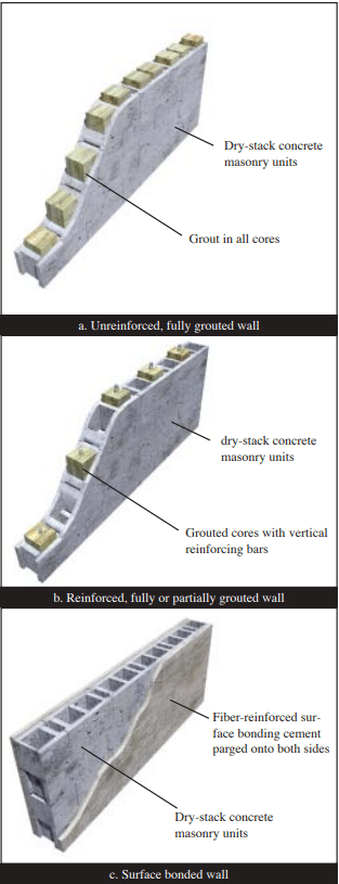
The equivalent thickness of a 100% solid unit or a solid grouted unit is equal to the actual thickness. For partially grouted walls where the unfilled cells are left empty, the equivalent thickness for fire resistance rating purposes is equal to that of an ungrouted unit. For partially grouted walls with filled cells, see the following section. Loadbearing units conforming to ASTM C90 (ref. 5) that are commonly available include 100% solid units, 75% solid units, and hollow units meeting minimum required face shell and web dimensions. Typical equivalent thickness values for these units are listed in Table 2.


Filling Cells with Loose Fill Material
If all cells of hollow unit masonry are filled with an approved material, the equivalent thickness of the assembly is the actual thickness. This also applies to partially grouted concrete masonry walls where all ungrouted cells are filled with an approved material.
Applicable fill materials are: grout, sand, pea gravel, crushed stone, or slag that comply with ASTM C33 (ref. 6); pumice, scoria, expanded shale, expanded clay, expanded slate, expanded slag, expanded fly ash, or cinders that comply with ASTM C331 (ref. 7); perlite meeting the requirements of ASTM C549 (ref. 8); or vermiculite complying with C516 (ref. 9).
Wall Assembly Fire Ratings
The fire resistance rating is determined in accordance with Table 1 utilizing the appropriate aggregate type used in the masonry unit and the equivalent thickness.
Units manufactured with a combination of aggregate types are addressed by footnote C, which may be expressed by the following equation (see also the blended aggregate example, below):

Blended aggregate example:
The required equivalent thickness of an assembly constructed of units made with expanded shale (80% by volume), and calcareous sand (20% by volume), to meet a 3-hour fire resistance rating is determined as follows. From Table 1:

Multi-Wythe Wall Assemblies
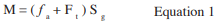
The fire resistance rating of multi-wythe walls (Figure 2) is based on the fire resistance of each wythe and the air space between each wythe using the following equation:

For multi-wythe walls of clay and concrete masonry, use the values in Table 3 for the brick wythe in the above equation.
Reinforced Concrete Masonry Columns
Concrete masonry column fire testing evaluates the ability of the column to carry design loads under standard fire test conditions. Based on a compendium of fire tests, the fire resistance rating of reinforced concrete masonry columns is based on the least plan dimension of the column as indicated in Table 4. The minimum required cover over the vertical reinforcement is 2 in. (51 mm).
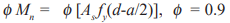
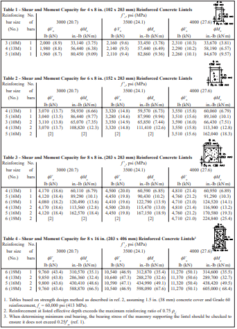
Concrete Masonry Lintels
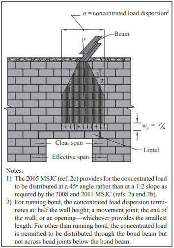
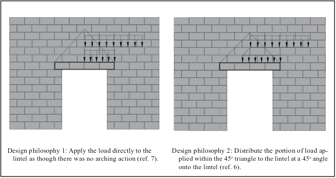
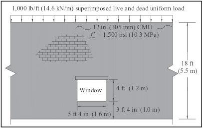
Fire testing of concrete masonry beams and lintels evaluates the ability of the member to sustain design loads under standard fire test conditions. This is accomplished by ensuring that the temperature of the tensile reinforcement does not exceed 1,100°F (593°C) during the rating period. The calculated fire resistance rating of concrete masonry lintels is based on the nominal thickness of the lintel and the minimum cover of longitudinal reinforcement (see Table 5). The cover requirements protect the reinforcement from strength degradation due to excessive temperature during the fire exposure period. Cover requirements may be provided by masonry units, grout, or mortar. Note that for 3 and 4 hour requirements, not enough cover is available for 6-in. (152 mm) masonry; however, if a special analysis indicates that the reinforcement is not necessary or not needed, such as when conditions for arching action are present, the cover requirements may be waived. See TEK 17-01D (ref. 11) for lintel design and conditions for arching action.
Control Joints
Figure 3 shows control joint details in fire-rated wall assemblies in which openings are not permitted or where openings are required to be protected. Maximum joint width is 1/2 in. (13 mm). Although these details are not directly in the IBC, they are included by reference in ACI 216.1/TMS 216.
In addition to these prescriptive fire resistance rated control joints, other control joints may be permitted in fire rated masonry walls. For example, the IBC and ACI 216.1/1/TMS 216 include provisions for ceramic fiber joint protection for precast panels, which are similar to concrete masonry walls in that both rely on concrete for fire protection, and both are governed by the ASTM E119 heat transmission criteria (see Figure 4). The first two categories of aggregate types in Table 1 would correspond to the carbonate or siliceous aggregate concrete curve and the last two aggregate categories of Table 1 would correspond to the semi-lightweight or lightweight concrete curve. For example, for an 8-in. (203-mm) limestone aggregate concrete masonry wall with a maximum control joint width of 1/2 in. (13 mm), a 1 in. (25 mm) thickness (measured perpendicular to the face of the wall) of ceramic fiber in the joint can be used in walls with fire resistance ratings up to 3 hours, while a 2 in. (51 mm) thickness can be used in the joints of a 4-hour wall.
Steel Columns Protected by Concrete Masonry
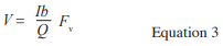
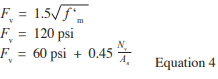
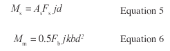
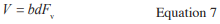
Fire testing of a steel column protected by concrete masonry evaluates the structural integrity of the steel column under fire test conditions, by measuring the temperature rise of the steel. The calculated fire resistance rating of steel columns protected by concrete masonry, as illustrated in Figure 5, is determined by:


Effects of Finish Materials on Fire Resistance Ratings
In many cases, drywall, plaster or stucco finishes are used on concrete masonry walls. While finishes are normally applied for architectural reasons, they can also provide additional fire resistance. The IBC and ACI 216.1/TMS 216 include provisions for calculating the additional fire resistance provided by these finishes.
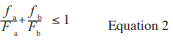
Note that when finishes are used to achieve the required fire rating, the masonry alone must provide at least one- half of the total required rating and the contribution of the finish on the non-fire-exposed side cannot be more than one-half of the contribution of the masonry alone. This is to assure structural integrity during a fire. The finish material must also be continuous over the entire wall.


Certain finishes deteriorate more rapidly when exposed to fire than when they are on the non-fire side of the wall. Therefore, two separate tables are required. Table 7 applies to finishes on the non fire-exposed side of the wall, and Table 8 applies to finishes on the fire-exposed side. For finishes on the non-fire exposed side of the wall, the finish is converted to an equivalent thickness of concrete masonry by multiplying the finish thickness by the factor given in Table 7. The result, Tef, is then added to the concrete masonry wall equivalent thickness, Te, and used in Table 1 to determine the wall’s fire resistance rating (i.e., the equivalent thickness of concrete masonry assemblies, Tea = Te Tef).
For finishes on the fire-exposed side of the wall, a time (from Table 8) is assigned to the finish. This time is added to the fire resistance rating determined for the base wall and nonfire-exposed side finish, if any. The times listed in Table 8 are essentially the length of time the various finishes will remain intact when exposed to fire (i.e., on the fire-exposed side of the wall).
When calculating the fire resistance rating of a wall with finishes, two calculations are performed, assuming each side of the wall is the fire exposed side. The fire rating of the wall assembly is the lower of the two. Typically, for an exterior wall with a fire separation distance greater than 5 ft (1,524 mm), fire needs be considered on the interior side only
Installation of Finishes
Finishes that contribute to the total fire resistance rating of a wall must meet certain minimum installation requirements. Plaster and stucco are applied in accordance with the provisions of the building code without further modification. Gypsum wallboard and gypsum lath are to be attached to wood or metal furring strips spaced a maximum of 16 in. (406 mm) o.c., and must be installed with the long dimension parallel to the furring members. All horizontal and vertical joints must be supported and finished.
UNCONVENTIONAL AGGREGATES
In recent years, manufacturers of concrete masonry products have been exploring the use of alternative materials in the production of concrete masonry units. Some of these materials have not been evaluated using standardized fire resistance test methods or have been evaluated only to a limited degree. Such unconventional materials, which are typically used as a replacement for conventional aggregates, may not be covered within existing codes and standards due to their novelty or proprietary nature.
While test methods such as ASTM E119 define procedures for evaluating the fire resistance properties of concrete masonry assemblies, including those constructed using unconventional constituent materials, there has historically been no defined procedure for applying the results of ASTM E119 testing to standardized calculation procedures available through ACI 216.1/TMS 216. To provide consistency in applying the results of full scale ASTM E119 testing to established calculation procedures, CMHA has developed CMU-FAQ-013-23 (Ref. 15).
This guideline stipulates that when applying the fire resistance calculation procedure of ACI 216.1/TMS 216 to products manufactured using aggregate types that are not listed in ACI 216.1/TMS 216, at least two full scale ASTM E119 tests must be conducted on assemblies containing the unconventional material. Based on the results of this testing, an expression can be developed in accordance with this industry practice that permits the fire resistance of units produced with such aggregates to be calculated for interpolated values of equivalent thickness and proportion of non listed aggregate.


REFERENCES
- Code Requirements for Determining Fire Resistance of Concrete and Masonry Construction Assemblies, ACI 216.1- 14/TMS216-14. American Concrete Institute and The Masonry Society, 2014.
- International Building Code 2015. International Code Council, 2015.
- Standard Test Methods for Fire Tests of Building Construction and Materials, ASTM E119-16a. ASTM International, Inc., 2016.
- Standard Methods for Sampling and Testing Concrete Masonry Units, ASTM C140-16. ASTM International, Inc., 2016.
- Standard Specification for Loadbearing Concrete Masonry Units, ASTM C90-16. ASTM International, Inc., 2016.
- Standard Specification for Concrete Aggregates, ASTM C33-16e1. ASTM International, Inc., 2016.
- Standard Specification for Lightweight Aggregates for Concrete Masonry Units, ASTM C331-14. ASTM International, Inc., 2014.
- Standard Specification for Perlite Loose Fill Insulation, ASTM C549-06(2012). ASTM International, Inc., 2012.
- Standard Specification for Vermiculite Loose Fill Thermal Insulation, ASTM C516-08(2013)e1. ASTM International, Inc., 2013.
- Steel Column Fire Protection, TEK 07-06A. Concrete Masonry & Hardscapes Association, 2009.
- ASD of Concrete Masonry Lintels Based on the 2012 IBC/2011 MSJC, TEK 17-01D. Concrete Masonry & Hardscapes Association, 2011.
- Standard Specification for Concrete Building Brick, ASTM C55 14a. ASTM International, Inc., 2014.
- Standard Specification for Calcium Silicate Brick (SandLime Brick), ASTM C73-14. ASTM International, Inc., 2014.
- Standard Specification for Prefaced Concrete and Calcium Silicate Masonry Units, ASTM C744-16. ASTM International, Inc., 2016.
- How is the fire resistance of a concrete masonry assembly calculated when using unconventional aggregates?, CMU-FAQ-013-23. Concrete Masonry & Hardscapes Association, 2023.
- What is the difference between fire resistance ratings for masonry assemblies obtained through IBC versus a listing service such as UL or FM?, CMU-FAQ-015-23. Concrete Masonry & Hardscapes Association, 2023.