Resources

Joint Sealants for Concrete Masonry Walls

INTRODUCTION

Successfully sealing joints, such as control joints and around door jambs and window frames, in concrete masonry walls depends on the overall design and construction of the entire building envelope. Movement joints (also called control joints) are needed in some concrete masonry walls to accommodate drying shrinkage, thermal movements, and movements between different building components. Movement joints, joints around fenestration, doors and penetrations, and isolation joints (joints at dissimilar material interfaces) rely on joint sealants to help preserve the overall weather-tightness of the building envelope. In addition, properly sealed joints may be required to meet a specified fire resistance rating or sound transmission class.

The sealant’s primary role is to deform as the joint moves, maintaining the seal across the joint. Most joint sealants are field-applied (as opposed to preformed). For instance, a raked-out mortar joint or open movement joint may receive sealant from a gun-squeezed cartridge, typically applied over a backup material.

This TEK provides a basic overview of joint sealants, installation guidelines to help ensure longevity, and recommended maintenance procedures, based primarily on ASTM C1193, Standard Guide for Use of Joint Sealants (ref. 1) and ASTM C1472, Standard Guide for Calculating Movement and Other Effects When Establishing Sealant Joint Width (ref. 2). This TEK does not address adhesives.

For optimum performance, the sealant must be properly applied to a well-constructed joint. For example, joints that are too thick relative to the width may cause failure of even the best sealant. Detailed information on control joint design and construction is available in CMU-TEC-009-23 (ref. 3).

JOINT SEALANTS AND RELATED MATERIALS

Control joints in concrete masonry construction are classified as butt-joints, where the sealant is exposed to cyclical tension and compression as the joint expands and contracts. Therefore, control joint sealants should be able to maintain their original shape and properties under these conditions. In addition, joint sealants should be impermeable, deformable to accommodate the joint movement, and be able to adhere to concrete and masonry materials or be used with an appropriate primer. The use of primers has been reported to improve bond as well as watertightness at the joint. Because many factors influence a wall’s water penetration resistance, the reader is referred to TEK 19-02B, Design for Dry Single-Wythe Concrete Masonry Walls (ref. 4) for more complete information.

Some variables to consider when selecting a joint sealant are the sealant’s: joint movement capability (typically reported as two percentages, one for elongation and another for compression), time to set-up/cure, adhesion/bond strength to concrete masonry or other substrates, hardness, tensile strength, durability, expected life in service, ease of installation, primer requirements, application temperature range, paintability, warranty requirements, and sag-resistance. Materials that dry out rapidly and/or do not effectively bond to masonry, such as most oil-based caulks, are generally not recommended for use as concrete masonry joint sealants.

In-service conditions for the particular application must also be considered. For example, for joints that are not exposed to the weather, aesthetic factors such as available colors may be more important than the weather-resistance of the joint. Other applications may require properties such as chemical or fire resistance.

In short, no single sealant will meet the requirements of every application. The following sections briefly describe the most common materials used for concrete masonry joints.

Masonry Joint Sealants

Sealants must comply with ASTM C920-11 Standard Specification for Elastomeric Joint Sealants (ref. 6). Sealants used for concrete masonry joints and at penetrations in concrete masonry walls may be polyurethanes, polysulfides, acrylics, silicones, or even modified blends of each. These sealant materials tend to have:

  • high resistance to aging and weathering,
  • good resistance to low-temperature hardening,
  • moderate resistance to age-related hardening,
  • high resistance to indentation,
  • low shrinkage after installation, and
  • nonstaining properties.

Backup Materials

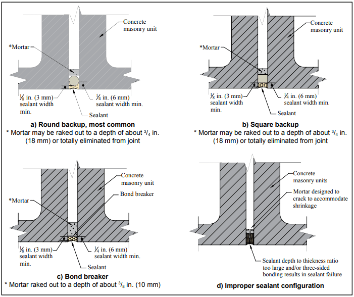
Backup materials are used to: restrict the sealant depth, support the sealant, facilitate tooling, and help resist indentation and sag. They may also serve as a bond breaker, preventing the sealant from adhering to the back of the joint. Backup materials for concrete masonry joints are commonly flexible foams, which are compressed into the joint using hand tools (see Figures 1a and 1b).

Backup materials for control joints must be compressible to accommodate masonry expansion (joint shrinkage), and must recover when the masonry shrinks (joint expands). Because the backup also needs to maintain contact with both joint faces when the joint expands, it is compressed when initially installed. Closed-cell backups should be sized 1 ¼ to 1  the joint width, so they are compressed 25% to 30% when placed in the joint. Open-cell backups, which are less stiff than closed-cell, should be sized 1 ½ times the joint width, so they are compressed about 50% of their undisturbed width when installed.

Bond Breakers

Bond breakers prevent three-sided adhesion of the sealant (i.e. from adhering to the back of a raked joint or to the backup), allowing the sealant to freely deform in response to building movements (see Figure 1c). Because many backup materials act as bond breakers, a separate bond breaker material is not always required. When it is, polyethylene tape, butyl tape, coated papers and metal foils can be used as well as polyurethane, polyethylene and polyolefin foams. Liquid-applied bond breakers are not recommended because of the likelihood of contaminating the sealant adhesion surface.

Primers

Primers, applied to the joint surfaces prior to sealant installation, are sometimes recommended to improve the sealant’s bond strength. In addition, some primers can tolerate application to damp masonry surfaces.

Check the sealant manufacturer’s recommendations for the particular sealant under consideration to determine whether or not a primer should be used on a masonry substrate. To ensure the primer and sealant will be compatible, use the primer recommended by the sealant manufacturer for the sealant being used.

Primer is applied by brush, roller or spray, and typically must dry or cure before sealant application. The recommended elapsed time between primer application and sealant application varies with type of primer, temperature and humidity.

JOINT SEALANT INSTALLATION

Like most materials, joint sealants should be installed in accordance with manufacturer’s instructions. Elements that are due special consideration, such as sealant depth and surface preparation are discussed in more detail below.

It is typically recommended that joint sealants not be applied during rain or snow, and that the masonry be clean and dry at installation. Installation temperature, i.e., the temperature of the masonry when the sealant is applied, may also be a consideration in some cases. Sealants installed at very low temperatures undergo compression as the wall warms up to the mean temperature, while a sealant installed at a high temperature is placed in tension at the mean temperature. For these reasons, it is desirable to have the installation temperature close to the mean annual temperature, although an in- stallation temperature range of 40° to 90°F (4.4 to 32.2°C) is generally considered acceptable for most applications, unless otherwise specified by the sealant manufacturer (ref. 6). Note that the masonry surface temperature may greatly exceed the ambient air temperature, especially on dark-colored and/or south- and southwest-facing walls in the sun.

Sealant Width and Depth

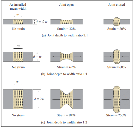
Sealant shape factor refers to the mean width versus mean depth of the sealant as installed in the joint. This ratio is important because it affects the amount of strain the sealant is exposed to as the joint moves, as well as the amount of sealant required to fill the joint (see Figure 1d). Sealants exposed to less strain can typically be expected to have a longer life, all other factors being equal. As illustrated in Figure 2, wider and shallower sealant profiles generally reduce strain and require less sealant.

In the field, sealant shape factor is controlled by varying the depth of the sealant, because the width of the joint is fixed at that point. The depth of sealant in the joint is typically controlled via the use of a backup material. Sealants that have a higher depth to width ratio tend to stretch more readily with joint movement, whereas with lower ratios the tendency is for the sealant to tear when subjected to movement. In general, for joint widths from ¼ to ½ in. (6 to 13 mm) the joint depth should be no more than the width of the joint. After the sealant is tooled, the minimum thickness of the sealant at the midpoint of the joint opening should not be less the in. (3 mm) and the sealant adhesion dimension no less than ¼ in. (6 mm) (refs. 1, 2). The required thicknesses also should be verified with the sealant manufacturer.

Joint Preparation

For all control joints, mortar should be raked out of the vertical joints on both sides of the panels. The mortar should be raked out at least ¾ in. (19 mm) to allow for a backup material and sealant ( in. (9.5 mm) if no backing is used). This also assures a plane of weakness at the control joint. Mortar in the control joint may also be totally omitted to ensure freedom of movement.

Proper surface preparation prior to sealant installation improves bond between sealant and masonry, and minimizes adhesion failures. Follow the sealant manufacturer’s recommendations regarding cleaning and/or priming the concrete masonry surface prior to applying sealant.

Backup materials must be installed to the proper depth in the joint to control the depth of sealant. Tools for placing backer materials can help ensure correct placement. Any tools used for placement should have a smooth surface adjacent to the backup, to avoid puncturing or otherwise damaging the backup material during placement.

Applying Sealant

Sealants may be either single- or multi-component. Multi-component sealants require thorough mixing, in accordance with the manufacturer’s instructions, to ensure uniform curing and to avoid over-mixing. Once mixed, the sealant has a limited pot life, so batch sizes should be matched to what can be installed within the pot life.

Masonry joint sealants are typically installed using a common caulk gun, with a tip the same size as the width of the joint. The caulk gun should be held at an angle of about 45° to the wall face, and moved slowly and consistently. Filling joints from bottom to top helps avoid trapping air as the sealant is placed.

Immediately after the joint is filled, the sealant should be tooled to a concave shape. Tooling helps ensure intimate contact between the sealant and masonry, consolidates the sealant, provides a concave profile and improves the appearance of the joint. The hour-glass shape shifts peak stresses away from the adhesion surface and to the middle of the sealant joint during joint movement. Most sealant manufacturers recommend dry-tooling for the best results.

MAINTENANCE

Properly maintained joint sealants will help maintain the water penetration resistance of the building envelope. Sealant materials cannot be expected to have the same life as a masonry building. For this reason, the sealant condition should be inspected on a regular basis, perhaps when the facade is cleaned, and repairs made as needed. Manufacturer’s recommendations should be used as a guideline to estimate sealant life. However, sealant life will vary greatly with exposure and the quality of the initial installation.

Because joint sealant adheres better to properly prepared surfaces, the old or deteriorated sealant should be completely removed from the joint and the joint cleaned prior to reapplication. Minor repairs can be made by cutting out the defective area and reapplying sealant of the same type. Sealants can be removed using a sharp knife to sever the sealant from the masonry. Although some manufacturers recommend more aggressive cleaning methods, such as sand-blasting or grinding, care should be taken when using these methods. For more detailed information on sandblasting, see TEK 08-04A, Cleaning Concrete Masonry, (ref. 6).

Once the joint is properly prepared, sealant can be installed as described above for new construction.

REFERENCES

  1. Standard Guide for Use of Joint Sealants, ASTM C1193-13. ASTM International, 2013.
  2. Standard Guide for Calculating Movement and Other Effects When Establishing Sealant Joint Width, ASTM C1472-10. ASTM International, 2010.
  3. Crack Control Strategies for Concrete Masonry Construction, CMU-TEC-009-23, Concrete Masonry & Hardscapes Association, 2023.
  4. Design for Dry Single-Wythe Concrete Masonry Walls, TEK 19-2B, Concrete Masonry & Hardscapes Association, 2012.
  5. Standard Specification for Elastomeric Joint Sealants, ASTM C920-11. ASTM International, 2011.
  6. Cleaning Concrete Masonry, TEK 8-4A. National Concrete Masonry Association, 2005.

Flashing Strategies for Concrete Masonry Walls

INTRODUCTION

The primary role of flashing is to intercept the flow of moisture through masonry and direct it to the exterior of the structure. Due to the abundant sources of moisture and the potentially detrimental effects it can have, the choice of flashing material, and the design and construction of flashing details, can often be as key to the performance of a masonry structure as that of the structural system.

The type of flashing material to be used is governed by both environmental and design/build considerations. Environmental considerations include such factors as the physical state of moisture present (liquid, solid, or vapor), air movement, and temperature extremes as well as temperature differentials. Design/build considerations include the selection of the proper type of flashing material, location of the flashing, structural, and installation details. Drawings for flashing details, often the only method of communicating the necessary information between the designer and contractor, should be comprehensive and show sufficient detail for the proper interpretation and installation of flashing systems. TEK 19-05A Flashing Details for Concrete Masonry Walls (ref. 3) includes such details.

Although flashing is the primary focus of this TEK, it should be understood that the role of vapor retarders, air barriers, and insulation are also important elements to consider for any wall design as the performance of the entire system can be dependent on the design of its individual components.

EFFECT OF MOISTURE ON MASONRY

The damage caused to a masonry structure (or its contents) due to the infiltration of moisture can take many forms, depending on the source and the physical state of the water. For example, in the liquid state, water penetrating to the interior of a building may cause considerable damage to its contents. In some extreme cases, water trapped within the masonry may freeze, inducing spalling and cracking of the masonry units or mortar. Alternatively, water vapor can lead to condensation inside the cores and on the surfaces of masonry if the dew point temperature is reached. During cold weather, below 28 °F (-2 °C), water vapor can accumulate on a cold surface and form frost or increase the quantity of ice within the masonry.

Although it is commonly thought that moisture problems stem only from the external environment, this is not always the case. For example, in some instances it is possible for the humidity of interior air to cause water damage to the exterior of a structure. This damage may appear in the form of water stains, ravelled mortar joints, spalled surfaces, or efflorescence.

DESIGN CONSIDERATIONS

Water Movement

In the design of any structure, the presence and movement of water in any of its three forms needs to be considered. Significant forces that influence water movement include wind pressure, gravity, and moisture absorption by the material. Dynamic wind pressure on the surface of an exposed wall can drive exterior moisture (in the form of rain or irrigation water) into the masonry. Gravity, which is always present, draws the free water vertically downward, while the absorptive characteristics of the masonry can cause moisture migration in any direction by capillary action.

It should also be recognized that these forces do not act independently of one another. For example, wind-driven rain may enter masonry through cracks at the interface between mortar and units and migrate downward through the wall due to the force of gravity, or it may be transferred horizontally through the wall either by pressure or by flowing across the webs of the units or mortar bridges. Wind-driven rain can also be absorbed by masonry units and carried from the exterior surface to the interior surface by capillary action. Additionally, ground water may be drawn upward by the wicking action of units placed on porous foundations or by contact with moist soil.

Designers should never assume that any material is capable of rendering a wall totally impervious to water penetration. Surface treatments, designed to reduce the quantity of water entering a masonry structure, are helpful in this regard but should not be considered as a sole means of protection. Available as clear and opaque compounds, the effectiveness of surface treatments depends on their composition and compatibility with the masonry. They also do not reduce the movement by capillary action (wicking) of any water that does penetrate the masonry face through cracks or defects in the mortar/masonry.

The use of integral water repellent admixtures in concrete masonry units and mortars can also reduce the amount of water entering the masonry. In addition, they inhibit water penetrating the masonry face from wicking to the back face of the wall.

Proper selection and application of surface treatments and integral water repellents can greatly enhance the water resistant properties of masonry, but they should not be considered as substitutes for flashing. See TEKs 19-01 and 19-02B (refs. 8 and 2) for more information on water repellents for concrete masonry.

Flashing Location

The proper design of masonry for resistance to water penetration includes consideration of the various types of wall construction such as single wythe, cavity, veneer, etc. During the design phase it should be understood that all exterior masonry walls may be subjected to some degree of water penetration and/or water vapor movement during its design life. Flashing is recommended for all locations where moisture may potentially penetrate into a wall and where the free drainage of water is blocked. Some of these critical locations include the top of walls and parapets, at all horizontal obstructions such as over openings, beneath sills, above shelf angles, at the base of walls, and in walls at ground level to serve as a moisture retarder to reduce the amount of water wicked up into the masonry above grade.

When selecting the flashing material for a particular application, the service conditions, projected life of the structure, and past performance characteristics of the flashing materials should be reviewed. Flashing should be designed to perform satisfactorily for the design life of the building since repair or replacement can be very labor intensive and expensive.

FLASHING MATERIALS

A wide variety of flashing materials are available. The selection of the type of flashing material to use can be influenced by several factors including cost, durability, compatibility with other materials, ease of installation, aesthetic value, and performance. Table 1 summarizes some of the attributes for various flashing materials. The advantages and disadvantages of each must be weighed for each individual project to provide the most cost-effective and desirable choice.

Prefabricated flashing boots may be available for inside and outside corners and end dams. These boots eliminate the need for cutting, folding, or tucking the flashing materials at these locations. However, due to construction tolerances, some of these prefabricated items, particularly those of rigid materials, may be difficult to fit into their intended location.

Sheet Metals

Stainless steel is technically any of a large and complex group of corrosion resistant iron chromium alloys possessing excellent weather and chemical resisting properties. Preformed sections must be properly sized so that on site modification is minimized. Stainless steel flashing with a conventional annealed finish should comply with Standard Specification for Stainless and Heat-Resisting Chromium-Nickel Steel Plate, Sheet, and Strip, ASTM A 167 (ref. 6). Generally, Type 304 stainless steel with a minimum thickness of 0.010 in. (0.25 mm) is satisfactory. Lap sections require solder conforming to Standard Specification for Solder Metal, ASTM B 32 (60% tin and 40% lead) (ref. 5). Stainless steel drip edges used in combination with other flashing materials offer an economical compromise with a durable drip edge.

Copper is a nonferrous metal possessing good ductility and malleability characteristics. Like stainless steel, it also possesses excellent weather and chemical resistant properties. Preformed sections or sheet materials are easily modified to conform to site requirements. However, it should be cautioned that once weathered, copper flashings produce a green patina that may impart a green stain to adjacent masonry surfaces that some find objectionable.

Galvanized steel is less expensive than stainless steel but is subject to corrosive attack from salts and acids. The galvanized coating also may crack at bends, lowering the corrosion resistance. As with stainless steel, it is also difficult to form and to solder laps effectively.

Composites

Combinations of metals and plastics are supplied by some dealers. The composition and application of these combined materials should be determined before use. Composites utilizing copper are the most popular since they combine the durability and malleability of copper with the nonstaining characteristics of a protective coating. Composites containing aluminum should be avoided.

Plastics and Rubber Compounds

Plastics are categorized as polymeric materials of large molecular weight, usually polyvinyl chloride (PVC) or polyethylene. Manufacturers of plastic flashings should be consulted for documentation establishing the longevity of the plastic in a caustic environment (pH = 12.5 to 13.5), the composition of the plastic, ease of working at temperatures ranging from 20 to 100 °F (-7 to 38 °C), and ability to withstand exposure to ultraviolet light.

Ethylene Propylene Diene Monomer (EPDM) is a synthetic rubber that is used as a single ply roofing membrane as well as flashing. It has better low temperature performance than PVC and will not embrittle. It offers ultraviolet light and ozone resistance and can be left exposed.

Self-adhering, rubberized asphalt membranes consist of a composite of flexible plastic film for puncture and tear resistance combined with a rubberized asphalt adhesive layer. This material adheres to itself, requiring less effort to seal laps or corners which speeds installation. It also self-adheres to the substrate which prevents water from migrating under the flashing and is self-healing in the event of punctures. However, it should not be applied to damp, dirty, or dusty surfaces and typically has a lower installation temperature limit of 25 °F (-4 °C). Because it degrades in the presence of extended UV exposure, it should not be left exposed and requires a metal drip edge.

CONSTRUCTION PRACTICES

To perform, flashing must be designed and installed properly or it may aggravate rather than reduce water problems. Flashing should be longitudinally continuous or terminated with end dams. Longitudinally continuous requires that joints be overlapped sufficiently, 4 in. (102 mm) minimum, to prevent moisture from entering between the joints and they must be bonded (joined) together with adhesive if they are not self adhering to prevent water movement through the lap area. With metal flashings a ¼ in. (6.4 mm) gap joined and sealed with a pliable membrane helps in accommodating expansion (ref. 3).

Flashings should be secured at the top by embedment into the masonry, a reglet, or should be adhesively attached so that water cannot infiltrate or move behind the attachment. For multi-wythe construction, the flashing should project downward along the outer surface of the inner wythe and then project outward at the masonry joint, shelf angle, or lintel where it is to discharge the water. Every effort should be made to slope the flashing towards the exterior. Effectively placed mortar or sealant material can help promote this drainage. The flashing should continue beyond the exterior face of the masonry a minimum of ¼ in. (6.4 mm) and terminate with a sloped drip edge.

An additional design consideration for flashings includes ensuring that all materials are compatible. For example, contact between dissimilar metals can result in the corrosion of one or both of the metals. Additionally, the coefficients of thermal expansion for the flashing and masonry materials differ. All flashing details should be designed to accommodate the resulting differential movement.

Other recommended practices involve the use of tooled concave mortar joints to reduce water penetration through the mortar joints. Masons should be careful to ensure that mortar dropped onto the flashing is minimized. This can be accomplished by beveling the mortar on the face shells adjacent to the cavities in cavity wall construction. In addition, cavity drainage mats, gravel beds, screens, or trapezoidal drainage material (filter paper) can be used to prevent mortar droppings from collecting on the flashing, which can form dams and block weep holes. Mortar collection devices at regular intervals or filling the cells with loose fill insulation a few courses at a time as the wall is laid-up, can be effective in dispersing minor mortar droppings enough to prevent clogging.

Weep holes, the inseparable companion to flashings, should provide free movement of water out of the concrete masonry cores, collar joints, or cavities. Any construction practice that allows forming the weep holes without inhibiting water flow may be used. Cotton sash cords and partially open head joints are the most common types of weep holes. Cotton sash cords should be removed prior to putting the wall into service to provide maximum unobstructed drainage. If necessary, insects can be thwarted by inserting stainless steel wool into the openings or using plastic or metal vents.

Vents

Weep holes often serve a dual function, first for water drainage and second as vents. Vents are desirable in some masonry wall systems to help reduce the moisture content of the masonry during drying periods. Air circulation through the cores and cavities within the masonry promotes equalization of moisture content throughout the masonry. Vents are considered desirable where air is confined within masonry, such as in parapets or areas of high humidity such as natatoriums.

MAINTENANCE

Maintenance programs should involve preserving the “as-built” design documents, records pertaining to inspections during the life of the structure, and continuing appraisal of the performance of the structure in addition to conventional repair and upkeep. Documentation of inspections, if efflorescence and water stains are observed, and logs of reported water penetration and their identified location, assist in determining proper corrective actions. Pictures with imprinted dates are suggested.

Knowledge of the wall design and construction can influence repair decisions. If flashing and weep holes were omitted during construction, it may prove effective to simply drill weep holes and vents to promote drainage and drying. Weep holes so drilled should be either at the intersection of the bed and head joints or into the cores at the bottom of the wall. Vents should be installed at the top of the wall or directly below bond beams. See TEK 08-01A Maintenance of Concrete Masonry Walls (ref. 4) for more detailed information on maintenance of concrete masonry walls.

When considering maintenance options, it is important to ensure that a masonry wall’s moisture control measures are kept intact. Thus, applying sealant beads, pargings, or coatings to a wall should be carefully weighed. Weep holes and vents should be maintained in an open condition to allow evacuation of moisture.

SUMMARY

Flashings are essential at foundations, bond beams, above and below openings, at shelf angles and at copings. Weep holes and vents reduce the moisture content of masonry walls. Proper selection of flashing materials, proper detailing, and proper installation will help ensure satisfactory performance.

REFERENCES

  1. The Building Envelope: Solutions to Problems, Proceedings from a national seminar series sponsored by Simpson Gumpertz & Heger Inc., 1993.
  2. Design for Dry Single-Wythe Concrete Masonry Walls, TEK 19-02B, Concrete Masonry & Hardscapes Association, 2012.
  3. Flashing Details for Concrete Masonry Walls, TEK 19-05A, Concrete Masonry & Hardscapes Association, 2008.
  4. Maintenance of Concrete Masonry Walls, TEK 08-01A, Concrete Masonry & Hardscapes Association, 2004.
  5. Standard Specification for Solder Metal, ASTM B 32-04, ASTM International, 2004.
  6. Standard Specification for Stainless and Heat-Resisting Chromium-Nickel Steel Plate, Sheet, and Strip, ASTM A 167-99(2004), ASTM International, 2004.
  7. Through-Wall Flashing, Engineering and Research Digest No. 654, Brick Industry Association.
  8. Water Repellents for Concrete Masonry Walls, TEK 19-01, Concrete Masonry & Hardscapes Association, 2006.


Roles and Responsibilities on Segmental Retaining Wall Projects

INTRODUCTION

On all construction projects, including those involving segmental retaining walls (SRWs), it is the owner’s responsibility to achieve coordination between construction and design professionals that ensures all required design, engineering analysis, and inspection is provided. In many cases, a design professional such as a site civil engineer or an architect acts as the owner’s representative. In either case, the owner or owner’s representative should ensure that the engineering design professionals’ scope of work, roles and responsibilities are clearly defined so that there is no ambiguity regarding responsibility for investigation, analysis and design, and that all required testing is performed.

The roles outlined in this TEK are typical industry roles for various engineering disciplines. SRW design and construction should generally follow these traditional roles. However, these roles may vary from project to project, depending on the contractual obligations of each consultant. For example, for simpler projects, such as residential landscapes, one design professional may take on the responsibility of several roles, if acceptable to local building code requirements.

For tall or complex walls and for commercial projects, each of these roles is likely to be provided by separate firms, each with expertise in a particular discipline. The discussion in this Tech Note is generally oriented towards projects where several design professionals are contracted.

Reinforced SRWs, because of their nature as composite soil structures, may have unique design and inspection considerations for the site civil engineer, the geotechnical engineer, and the independent testing agency. These considerations are discussed in further detail in the following sections.

Detailed guidance on SRW design, construction and inspection can be found in references 1 through 3.

OVERVIEW OF ROLES

The owner/developer, or a designated representative, is ultimately responsible for ensuring that all applicable requirements of governing authorities for the permitting, design, construction and safety on the project are addressed. The owner or owners’ representative should ensure that the types of retaining walls specified are appropriate for the site conditions and ensure the wall alignment fits within the site’s space limitations. It is the owner’s or owner’s representative’s responsibility to contract an engineer to provide site civil engineering including site layout, drainage and grading. The owner must also ensure that a geotechnical engineer and testing agency are contracted to provide all necessary and required soils exploration, analysis and earthwork inspection for the entire project, including in the vicinity of the SRWs, just as they do in the vicinity of building structures. The owner or owner’s representative must also ensure that a qualified wall design engineer provides an SRW structural design.

The most straightforward means for the owner or owner’s representative to ensure all engineering roles are well-defined is for the SRW design engineer’s assigned roles to be the same as those traditionally given to a structural engineer designing a cast-in-place concrete retaining wall, and for the other design professionals, such as site civil and geotechnical engineers, to also provide the same roles and services as they would for a cast-in-place retaining wall.

Table 1 contains an itemized list of the suggested roles for each professional discipline for larger walls and commercial projects involving SRWs. A more thorough explanation of the site civil engineer’s, geotechnical engineer’s and SRW engineer’s roles, and construction observation and testing roles is provided in the following sections. The actual responsibilities for each discipline should be contractually based.

SITE CIVIL ENGINEER SUGGESTED ROLES OVERVIEW

It is suggested that the site civil engineer be contracted for all traditional site civil duties, including the design of surface drainage, storm drainage collection structures, utility layout, erosion control and scour protection. The site civil engineer is also typically responsible for site layout and grading plans, including slopes and retaining wall locations. The site civil engineer should, in consultation with the geotechnical engineer, ensure that all planned grades, including those at the top and bottom of SRWs, do not exceed the stable slope angles and do not cause surface drainage or erosion problems.

The site civil engineer should also plan the wall alignment so that the SRW structure does not encroach on any easements. In addition, the site civil engineer should be responsible for any other issues related to the wall location, such as proximity to property lines, utilities, watersheds, wetlands, or any other easements. In some cases, the site civil engineer may also act as the SRW Design Engineer and take on suggested roles for the SRW Engineer discussed below.

The site civil engineer should evaluate and design for any hydrologic issues and structures such as: culverts, open channels, detention/retention ponds, scour and erosion control details, as well as defining high water levels, flow volumes, flood areas and scour depths. The site civil engineer should provide any pertinent hydrologic data that may affect the SRW to the SRW engineer.

Often, when not designing the SRW in-house, the site civil engineer specifies the engineering design of SRWs to be part of the SRW construction contract (a design/build bid). While a common practice, this type of bid can place the SRW engineer in a different position than other project engineers. Unlike other engineers working directly for the owner, the SRW engineer in this design/build case is often working directly for a contractor, who is often a subcontractor to other contractors. This can cause design coordination issues because the SRW engineer may not be included in project discussions with other engineers, such as pre-construction meetings. Therefore, it is suggested that the site civil first determine if it is appropriate to have the SRW engineering specified as part of the wall construction contract. For some more complicated projects, it may be preferable to have the SRW design engineer perform the design prior to bidding the construction rather than as part of a design/build bid. If the site civil engineer chooses to specify the SRW design as part of the construction bid, it is recommended that the site civil engineer ensure that the SRW design engineer is involved in any required design and construction observation services before and during construction, similar to the way geotechnical engineers are often contracted for their services during construction.

GEOTECHNICAL ENGINEER SUGGESTED ROLES OVERVIEW

The geotechnical engineer should typically be contracted to provide the same engineering roles in the vicinity of the SRW as they do for all other structures on site. The geotechnical engineer’s typical roles are the investigation, analysis and testing of the site soil materials and groundwater conditions. Just as geotechnical engineers traditionally provide bearing capacity, settlement estimates and slope stability analysis for building structures, it is suggested they do the same for SRWs. The geotechnical engineer’s role should include providing soil properties such as soil shear strength parameters, ground water elevation, seismic conditions, and bearing capacities to the SRW engineer.

Responsibility for slope stability evaluation around an SRW can be a source of confusion, because the SRW engineer can often address slope stability issues near a geosynthetic-reinforced SRW by modifying the geosynthetic reinforcement layout. Thus, the SRW engineer is sometimes requested to evaluate and design for slope stability by the civil engineer’s specifications. However, involving the SRW engineer in addressing slope stability should not remove ultimate global/slope stability responsibility from the geotechnical engineer.

It is therefore suggested that, regardless of the SRW engineer’s involvement, the geotechnical engineer be contracted to have the ultimate responsibility for the site’s slope stability, including: determining when and where global stability analyses are required, determining the appropriate soils and groundwater properties to be used for the analyses, and ensuring that all required failure planes are analyzed. While the geotechnical engineer may need to coordinate with the SRW engineer for evaluating potential failure planes that pass through the reinforced soil (compound failures), the geotechnical engineer has the primary responsibility for these analyses.

When the geotechnical consultant is retained to provide construction observation and soils testing for a project, the contract should include inspection and testing of SRW earthwork along with all other earthwork on site. See TEC-008-12, Inspection Guide for Segmental Retaining Walls (ref. 3) for further discussion of inspection roles.

While geotechnical engineers should be contracted for the same traditional roles regarding SRWs as for other structures, the soils engineering for SRWs may require some slightly different methods of analysis compared to evaluating soils below rigid structures on spread footings. Design guidelines for SRWs are provided in Reference 1.

SRW DESIGN ENGINEER SUGGESTED ROLES OVERVIEW

As noted previously, the SRW design engineer should serve the same roles for SRWs as a structural engineer would for the design of a cast-in-place concrete retaining wall. In some cases, the site civil engineering firm may also act as the SRW engineer, while in others, the SRW design engineer will be a separate firm. The SRW design engineer should design a stable SRW, given the specified wall geometry and site conditions provided by the site civil and geotechnical engineers. The SRW engineer’s duties typically include determining the SRW’s maximum stable unreinforced height and providing a geosynthetic reinforcement layout design when required.

The SRW design engineer is typically responsible for preparing the SRW construction drawings, and for determining the internal stability, facial stability of the SRW units, internal drainage of the SRW (both at the face of the wall and at the rear of the reinforced soil mass, if required), external stability (sliding and overturning), and internal compound stability.

The SRW designer engineer’s output generally consists of specifications of wall components, a wall elevation detail, typical cross sections, details for any required drainage materials within or just behind the wall system, and details for how to incorporate any other structures (utilities, pipe penetrations, posts, etc.), if feasible, within the reinforced zone and wall face.

The SRW design engineer should typically not assume any duties typically relegated to the geotechnical engineer elsewhere on site. While an SRW engineer may be asked to participate in addressing the slope stability immediately around the SRW or foundation improvements in the soil below an SRW, it is recommended that the geotechnical engineer be clearly contracted to have ultimate responsibility for all slope stability and bearing capacity/settlement concerns on site, including those below and around SRWs.

It is appropriate that the SRW engineer be contracted to provide services during construction, especially on larger projects, but it is recommended that these not be included in a design/build contract for the wall construction. Time lag between design and construction can make it impractical to expect the designer to be available for services during construction and, given the often unpredictable extent and timing of construction, it is inappropriate to have services during construction be in a lump-sum design/build contract. Rather, it is suggested that the SRW engineer be hired under a separate contract directly with the owner or owner’s representative to provide services during construction. These services may include preconstruction correspondences and meetings, review of materials submittals, review of earthwork testing performed by the geotechnical engineer, and review of the wall contractor’s building practices.

CONSTRUCTION OBSERVATION AND TESTING SUGGESTED ROLES OVERVIEW

The soil in the reinforced zone should be checked to ensure it meets specifications; just as concrete and steel are inspected in a cast-in-place concrete retaining wall.

The wall contractor is responsible for quality control of the wall installation: performing necessary observation and testing to verify that the work performed meets minimum standards.

It is the owner’s or owner’s representative’s responsibility to perform quality assurance: auditing and verifying that the quality control program is being performed properly.

Just as is done for building structures and cast-in-place concrete retaining walls, foundation and retained soils should be evaluated for consistency with the soil properties used in the design. Generally, the geotechnical engineer evaluates the onsite soil conditions and performs earthwork testing. It is suggested that the geotechnical engineer perform any field and laboratory testing they deem required to verify soil conditions. The geotechnical engineer should confer with the SRW engineer regarding the reinforced soil specifications and provide the SRW engineer with the fill soil test results. The geotechnical engineer should also determine the frequency of tests required to ensure that compaction of the SRW reinforced fill meets the project specifications.

OWNER SUGGESTED ROLES OVERVIEW

Segmental retaining walls are designed to provide a long life with little to no maintenance required. After the SRW installation is complete, some very basic maintenance will help maximize the SRW project’s beauty and durability.

The most basic maintenance task is a periodic visual assessment of the SRW units and overall wall. If coatings have been applied to the wall, the need for re-coating should be assessed based on the coating manufacturer’s recommendations and the exposure conditions of the wall. Table 2 lists regular inspection tasks that can be performed on SRWs and their suggested frequency.

Periodic cleaning of SRWs may be desired to maintain the wall’s aesthetics. Cleaning recommendations for SRWs are essentially the same as those for other concrete masonry walls. The reader is referred to: TEK 8-04A, Cleaning Concrete Masonry; TEK 08-02A, Removal of Stains from Concrete Masonry; and TEK 08-03A, Control and Removal of Efflorescence (refs. 5, 6, 7), for more detailed guidance.

In addition to maintenance and cleaning, the owner is also responsible for ensuring that subsequent digging or trenching, such as for landscaping, does not impact the SRW installation. During any excavation, care should be taken to leave a zone of undisturbed soil behind the segmental retaining wall. Particular care should be taken to ensure that excavation does not damage, cut or remove the geosynthetic soil reinforcement, if present. For this reason, the owner should maintain a record of the installation, including the locations of geosynthetic reinforcement.

Once established, tree roots do not typically damage an SRW. The roots will typically not damage the wall face from behind because the drainage aggregate behind the SRW face does not support root growth. In fact, the root system can act as additional soil reinforcement, helping to further stabilize the soil. When newly planted, trees and other large vegetation should be adequately supported to prevent them from toppling and potentially damaging the SRW.

REFERENCES

  1. Design Manual for Segmental Retaining Walls, Third Edition, SRW-MAN-001-10, Concrete Masonry & Hardscapes Association, 2010.
  2. Segmental Retaining Wall Installation Guide, SRWMAN-003-10, Concrete Masonry & Hardscapes Association, 2010. 
  3. Inspection Guide for Segmental Retaining Walls, SRW-TEC-008-12, Concrete Masonry & Hardscapes Association, 2012. 
  4. Maintenance of Concrete Masonry Walls, TEK 08-01A, Concrete Masonry & Hardscapes Association, 2004. 
  5. Cleaning Concrete Masonry, TEK 08-04A, Concrete Masonry & Hardscapes Association, 2005.
  6. Removal of Stains from Concrete Masonry, TEK 08-02A, Concrete Masonry & Hardscapes Association, 1998.
  7. Control and Removal of Efflorescence, TEK 08-03A, Concrete Masonry & Hardscapes Association, 2003.

Control and Removal of Efflorescence

INTRODUCTION

Efflorescence is a deposit of soluble salts and bases, usually white in color, that sometimes appear on the surfaces of masonry or concrete construction. Although it may be an aesthetic concern, efflorescence will not affect structural performance.

Often efflorescence is apparent just after the structure is completed. If the efflorescence is essentially uniform throughout the exterior facade, it indicates normal water loss from the materials and the building. Some identify this occurrence as “early age” efflorescence or “new building bloom”. If unattended, the salts will eventually be removed by rain water.

If the deposit is heavy and essentially shows as white streaks immediately below mortar joints or covering localized areas of the masonry, it indicates that water has entered or is entering the wall at a higher elevation. These salts are called leachates, referred to “lime spots”, “lime runs” and “lime deposits”; and are sometimes identified as “late age” or recurrent efflorescence. Late age or recurrent efflorescence usually consists of more permanent surface accumulations and indicates a need for corrective measures.

This TEK discusses the various mechanisms which cause efflorescence and presents recommendations for its control and removal.

CAUSES OF EFFLORESCENCE

A combination of circumstances causes efflorescence. First, there must be soluble compounds in the masonry. Second, moisture must be present to pick up the soluble salts and carry them to the surface. Third, some force—evaporation or hydrostatic pressure—must cause the solution to move. If any one of these conditions is eliminated, efflorescence will not occur.

Source of Salts

The individual elements and compounds associated with efflorescence may be present in concrete masonry units, mortar and grout. However, efflorescence of masonry is generally attributed to water soluble sodium, potassium and calcium.

These solutions either precipitate as hydroxides or combine with atmospheric carbon dioxide and sulfur trioxide. The compounds produced by the combination of these elements are white or yellow salts, all of which are less water soluble than their former hydroxide counterparts. Chlorides are usually a result of contamination of masonry units and sand by sea water or runoff from alkaline soils. Since chloride salts are highly soluble in water, rain will often wash them off.

The amount and character of the deposits vary according to the nature of the soluble materials and the atmospheric conditions. Efflorescence is particularly affected by temperature, humidity and wind. In the summer, even after long rainy periods, moisture evaporates so quickly that comparatively small amounts of efflorescence are brought to the surface. Thus, efflorescence is more common in the winter when a slower rate of evaporation allows migration of salts to the surface. In spring, condensation frozen within the masonry may be released by warm weather allowing for further solubilizing of compounds and their migration to the surface. With the passage of time, efflorescence becomes lighter and less extensive unless an external source of salts or recurrent water migration is present.

In most cases, compounds that cause efflorescence are water soluble and are left on the surface as the water containing them evaporates. Sometimes, however, chemicals in the construction materials react with chemicals in the atmosphere to form the efflorescence. In the case of concrete masonry or mortar, the hydrated cement contains some calcium hydroxide (soluble) as a product of the reaction between cement or lime and water. When this calcium hydroxide is brought to the surface by water it combines with carbon dioxide in the air to form calcium carbonate (slightly soluble), which then appears as a whitish deposit.

Cements used in the production of mortar and concrete masonry units contain small amounts of water soluble compounds of sodium and potassium. Such water soluble alkalis, present as only a few tenths of one percent, can appear as efflorescence when leached out of the masonry by migrating moisture and concentrated at some point on the surface.

In addition to the masonry materials, building trim such as concrete copings, sills and lintels may also contain considerable amounts of soluble compounds. Some admixtures or ground water may also contribute to efflorescence. Most admixtures are proprietary and their compositions are not disclosed. Accordingly, the efflorescence potential of such admixtures should be determined by experience or laboratory tests. Dispersing agents used in pigments may increase the potential for efflorescence.

Sources of Moisture

Water serves as the vehicle by which soluble salts and bases are transported to the surface, where they accumulate as the water evaporates. The primary source of moisture is rain water. Rain water may enter the wall through one or more of the following paths permeable masonry units, partially filled mortar joints, inadequate flashing and sealing details, and cracks or other openings in the wall.

Considerable moisture may also enter a masonry wall as vapor from the interior of a building and accumulate within the wall as it condenses. Excessive accumulation of condensed water vapor may lead to efflorescence.

A third source of moisture that may contribute to the future formation of efflorescence is water that enters the masonry during construction. Improper protection of masonry during and after construction can allow considerable moisture to enter, which can cause efflorescence.

Masonry in contact with soil, such as in basement and retaining walls, may absorb ground water containing soluble salts. Through capillary action, salts present in the soil may rise several feet above the ground, producing an accumulation of salts in the masonry.

CONTROL OF EFFLORESCENCE

Since many factors influence the formation of efflorescence, it is difficult to predict if and when it will appear. However, to reduce the probability of efflorescence occurring in masonry construction, it is necessary to minimize the amount of soluble salts and moisture present in the masonry. Of the two, moisture is the more easily avoided.

Design

The reduction of moisture in concrete masonry will minimize the mechanisms that cause efflorescence. The designer must review each area of the design prior to construction to see if water can enter and where it will flow or accumulate if it does enter.

The selection of wall type—single-wythe, multi-wythe or cavity should be considered from the standpoint of resistance to rain penetration and the exposures to which it may be subjected. Design details that will prevent the entrance of moisture into the masonry assembly are critical. Details that will direct water collection away from wall tops and horizontal surfaces should be considered. If architecturally feasible, wide overhanging roofs help protect walls from rainfall.

Parapets require special attention because of their exposure.

Flashing should be installed in locations where water will tend to accumulate (i.e., parapets, spandrels, lintels, base of wall) within the masonry. The flashing should be installed to direct the water outward through weep holes.

Joints between masonry and door and window openings should be given careful attention during design as well as construction. Backer rods and sealants should be properly selected and installed in the same careful manner as other elements in the structure. TEK 19-02B Design for Dry Single-Wythe Concrete Masonry Walls and TEK 19 04A Flashing Strategies for Concrete Masonry Walls (refs. 1, 2) provide a more complete discussion on the proper use of flashings and details to minimize water entry.

Numerous surface treatments are available for the construction of weathertight concrete masonry walls. Properly applied, coatings can be relied on to give a satisfactory weathertight concrete masonry wall for up to 10 years in most geographic areas. Clear water-repellent surface treatments decrease efflorescence by repelling water from entering the masonry. However, the application of clear coatings to a masonry wall that has the tendency to effloresce, without reducing the mechanisms for the occurrence of that efflorescence, may lead to surface spalling of masonry units or deposits on the interior and/or exterior surface of the surface treatment.

The designer and owner may also want to consider the use of integral water repellents in the masonry. Integral water repellent admixtures have been shown to reduce the tendency to effloresce, since they reduce water migration throughout the wall. For more information on surface treatments and integral water repellents see TEK 19-01 Water Repellents for Concrete Masonry Walls (ref. 3).

Materials

In the selection of masonry materials, all component parts—masonry units, mortar and grout—should be considered for their soluble salt content.

At present there is no standard test for evaluating the efflorescence potential of concrete masonry units or mortar. However, in light of this absence, Standard Test Methods of Sampling and Testing Brick and Structural Clay Tile, ASTM C 67 (ref. 4) which does contain a test method to estimate efflorescence potential, is occasionally specified to evaluate concrete masonry units for efflorescence potential.

All cement should meet applicable ASTM specifications. Lime should be hydrated lime and should meet the requirements of ASTM C 207 (ref. 5). Sand should meet the requirements of ASTM C 144 (ref. 6) and clean mixing water should be used.

If walls of hollow masonry units are to be insulated by filling the cores, the insulating material should be free of harmful salts.

Construction

Materials received at the construction project should be properly stored throughout the construction process. Units should be stored on pallets, or otherwise isolated from the ground, and be adequately covered to prevent water absorption.

Materials removed from stockpiles should be handled such that they remain protected from rain and soil. If colored units are involved, the distribution from the stockpile should be such that the color range of the units is known and units with acceptable color variations are uniformly dispersed throughout the field of the masonry.

During construction, the mixer, mortar box and mortar boards should be kept clean. During cold weather construction, this equipment should not be deiced with salt or antifreeze material. Tools should also be clean and free of rust, salts and other harmful material. For example, workers should not use a shovel for salt and then use it for sand without first thoroughly washing the shovel.

Inadequate hydration of cementitious materials caused by cold temperatures, premature drying or improper use of admixtures should be prevented.

At the end of the work day and after completing one segment of masonry, the top surface of the masonry should be protected to prevent water penetration. Uncovered masonry walls are vulnerable to large quantities of water entering the wall.

Close cooperation between the masonry contractor and designer is necessary to ensure good design and detailing are correctly carried through the construction. Workmanship greatly influences the weathertightness of concrete masonry walls. Concave or vee-shaped mortar joints should be used where the masonry will be subjected to rain or freeze-thaw exposure. Tooling of the joints should be delayed until the mortar is “thumbprint hard”. This partial setting of the mortar provides resistance to the tooling action and forces the mortar tightly against the face shell of the unit to form a good weathertight seal. Joints that do not provide compression of the mortar during the tooling process such as raked, flush, and cut joints are not recommended for exterior applications. They not only do not provide the necessary compressing action against the unit, but by their very nature, leave a ledge for water to accumulate and slowly soak into the masonry.

Head joints are more vulnerable to leakage and poor workmanship as the force of gravity is not working to compress the mortar against the unit to provide a good seal. Head joints must be properly filled to the full thickness of the face shell and compacted by shoving the unit being placed against the previously laid unit. Then of course, the joint must be properly tooled. The use of water to remove surface accumulations, including efflorescence, will cause additional water to enter the wall particularly if it is applied under high pressure. This water may promote further efflorescence.

REMOVAL OF EFFLORESCENCE

Before any effort to remove the efflorescence is undertaken, the reason for the efflorescence should be established. If it is “early age efflorescence,” moist construction materials may be the cause. If “late age efflorescence” is observed, the possibility of water leakage should be investigated. If the efflorescence is near ground level, ground water may be the cause. In any case, the problem should be repaired prior to removing the efflorescence. Generally, if efflorescence is the main concern regarding masonry surface discoloration, the masonry walls should be allowed to cure and then the salts should be removed.

Compared to other stains, the removal of most types of efflorescence is relatively easy. As stated previously, most efflorescing salts are water soluble and many will disappear with normal weathering unless there is some external source of salts.

In general, most efflorescence can be removed by dry brushing followed by flushing with clean water. If brushing is not satisfactory, it may be necessary to use a very light (brush) sandblasting to remove the deposits. Brush sandblasting is sandblasting which is light enough that coarse aggregate is not exposed by the sand blasting (ref. 7). Sand blasting needs to be done with care, as it can alter the appearance of masonry by roughening the surface or exposing aggregate. There also are a variety of commercial cleaners available which may be effective for efflorescence removal. Consult manufacturer’s information for applicability.

As a last resort, a dilute solution of muriatic acid (5 to 10 percent) is sometimes used to clean the wall. For integrally colored masonry, a more dilute solution (2 percent) may be necessary to prevent surface etching that may alter colors and textures. Before an acid treatment is used on any masonry wall, the solution should be tested on a small, inconspicuous portion to be sure there is no adverse effect.

Before applying an acid solution, always wet the wall surface with clean water to prevent the acid from being absorbed deeply into the wall where damage may occur. Application should be to small areas of not more than 4 ft 2 (0.37 m2) at a time, with a delay of about 5 minutes before scouring the salt deposit with a stiff bristle brush. Use a special acid cleaning brush. Do not use a wire brush as the filings of wire left behind could result in further staining as the steel corrodes. After this treatment, the surface should be immediately and thoroughly flushed with clean water to remove all acid. If the surface is to be painted, it should be thoroughly flushed with water and allowed to weather for at least one month.

Since an acid treatment may slightly change the appearance, the entire wall should be treated to avoid uneven discoloration or mottled effects. Windows, doors, or surrounding materials may need to be protected during application.

Calcium carbonate efflorescence is extremely difficult to remove. It appears usually as a flat white deposit and in the worst cases forms a hard white crust. Any effective methods of removal can alter the texture of the block to such an extent that it is necessary to treat the entire wall area and not merely the affected regions. One method of removal reported to be effective is the use of high pressure water jet, sometimes augmented with the addition of fine sand to the water.

REFERENCES

  1. Design for Dry Single-Wythe Concrete Masonry Walls, TEK 19-02B, Concrete Masonry & Hardscapes Association, 2012.
  2. Flashing Strategies for Concrete Masonry Walls, TEK 19-04A, Concrete Masonry & Hardscapes Association, 2003.
  3. Water Repellents for Concrete Masonry Walls, TEK 19-01, Concrete Masonry & Hardscapes Association, 2002.
  4. Standard Test Methods for Sampling and Testing Brick and Structural Clay Tile, ASTM C 67-02c, American Society for Testing Methods, Philadelphia, PA 2002
  5. Standard Specification for Hydrated Lime for Masonry Purposes, ASTM C 207-91(1997). American Society for Testing and Materials, 1997.
  6. Standard Specification for Aggregate for Masonry Mortar, ASTM C 144-02, American Society for Testing Methods, Philadelphia, PA, 2002.
  7. Maintenance of Concrete Masonry Walls, TEK 08-01A, Concrete Masonry & Hardscapes Association, 1998.

Removal of Stains From Concrete Masonry

INTRODUCTION

With the continued use and expanding applications of architectural concrete masonry, segmental retaining wall units, and concrete pavers, exposed concrete masonry is becoming common across the country. Although maintenance of a well designed and constructed masonry wall is minimal, inadvertent staining from oil, grease, or other foreign substances can destroy the appearance of an otherwise attractive unpainted masonry structure. This publication provides information on effective methods for removing some of the most common stains.

STAIN PREVENTION

Many stains can be prevented or minimized through proper design, construction, and maintenance procedures. For instance design details that prevent or reduce water intrusion reduce the chance that efflorescence will occur – see Maintenance of Concrete Masonry Walls, TEK 08-01A (ref. 1).

During construction of exposed concrete masonry, minimize mortar and grout smears on the face of the units. Mortar droppings which adhere to the exposed face of the units can be removed with a trowel or chisel after being allowed to harden. Any remaining mortar can then be removed with a stiff fiber brush. Also, the base of the wall should be protected from splashing mud and mortar droppings by spreading plastic sheets 3 to 4 feet on the ground and 2 to 3 feet up the wall. Covering the tops of unfinished walls at the end of the workday prevents rain from entering the wall and thus reduces the chance of efflorescence forming on the wall. Covers should be draped at least two feet down each side of the wall and a method provided to hold them in place. See Cleaning Concrete Masonry, TEK 08-04A (ref. 6) for more information on cleaning concrete masonry during construction and further information on cleaning concrete masonry.

PLANNING AND PRECAUTIONS

The cleaning procedure should be carefully planned. No attempt should be made to remove a stain until it is identified and its removal agent determined. If the staining substance cannot be identified, it is necessary to experiment with different methods on an inconspicuous area. The indiscriminate use of an inappropriate product or the improper application of a product may result in spreading the stain over a larger area or in causing a more unsightly, difficult to remove stain. Removing stains from concrete masonry sometimes can leave the treated area lighter in color than the surrounding area because surface dirt has been removed along with the stain or the surface has become slightly bleached. This is particularly true for buildings that are several years old. This may necessitate treating the entire wall. Materials such as glass, metal, wood or architectural concrete or concrete masonry adjacent to the area to be cleaned should be adequately protected since they may be damaged by contact with some stain removers or by physical cleaning methods.

Many chemicals can be applied to concrete masonry without appreciable injury to the surface, but strong acids or chemicals with a strong acid reaction definitely should be avoided. Even weak acids should be used only as a last resort as it dissolves the cement matrix of the masonry beginning at the surface. This leaves the face more porous so that it absorbs more water and exposes more aggregate thereby changing the color and texture of the masonry.

CLEANING METHODS

The methods of cleaning concrete masonry can generally be divided into three categories water cleaning, abrasive cleaning, and chemical cleaning (ref. 2).

Water Cleaning

Water cleaning includes the use of water soaking, steam cleaning and pressure washing. Cleaning of unpainted walls can usually be accomplished by scrubbing with water and a small amount of detergent. Clay or dirt first should be removed with a dry brush. Steel wire brushes should not be used because they can leave metal particles on the surface of the masonry that later may rust and stain the masonry. Nonmetal brushes such as stiff fiber or nylon are preferred. Soaking with water causes dirt deposits to swell, loosening their grip on the underlying masonry and then allowing them to be flushed away with water. Some efflorescence can be removed when it first appears by dry brushing followed by flushing with water. More extensive efflorescence may require brushing with acid see the section on chemical cleaning or Control and Removal of Efflorescence, TEK 08-03A (ref. 3).

Heated water is useful on greasy surfaces or during cold weather. However, warm water when used with alkaline chemicals, should not exceed 160° F (71° C). There is no significant advantage to using hot water with acid cleaners (ref. 2).

Steam cleaning virtually has been supplanted by improved and innovative pressure washing equipment. However, by supplementing heat to the soaking with water, the action of loosening and softening of dirt particles and grease is improved allowing them to be more easily rinsed away. The steam is normally generated in a flash boiler and directed toward the stain by means of a wand at a pressure of 10 to 80 psi depending on the equipment used. A drawback with steam cleaning is that is rather slow when compared to pressure washing. An advantage of steam cleaning is that it essentially leaves the concrete masonry surface intact.

High-pressure washing equipment can be extremely effective for restorative cleaning of older masonry; however, when improperly applied, it can cause severe damage. If pressure application of chemical cleaning agents is considered, the surfaces to be cleaned must be thoroughly prewetted, cleansing agents must be prediluted, and the application pressures should be kept to a minimum. High pressure washing, however, should not be mistaken as a total replacement for hand labor. The mild agitation created by brush application improves the overall cleaning results while enabling rinsing pressure to be kept to a minimum.

Abrasive Cleaning

The objective in abrasive cleaning is not to dissolve and wash away the stain, but to remove the outer portion of the masonry in which the stain is deposited. Included in this category are grinding wheels, sanding discs, sanding belts, and the more popular grit blasting. Silica sand in recent years has been replaced as the abrasive blasting material by other products such as crushed slag in the concern over health hazards posed by airborne silica dusts. Protective equipment and clothing must be used, including an approved respirator under a hood.

Care must be exercised when using abrasive cleaning techniques since over zealous applications can cause drastic changes to the appearance, durability, and water tightness of the masonry. To minimize this, softer, less damaging abrasives such as crushed cornhusks, walnut shells, glass beads, etc. can be used on more delicate surfaces. This process, sometimes called micro-peening, is slower and more costly and generally is not applicable to large scale cleaning operations.

Most of the dust that accompanies the dry process can be eliminated with wet abrasive cleaning by introducing water into the air-grit stream at the nozzle. However the smaller, harmful particles remain a health hazard so the same protective equipment and clothing are needed as for the dry process. The wet process requires the extra step of rinsing down the cleaned surface after blasting.

Needless to say, previously applied waterproofing agents are removed during the abrasive cleaning process. Therefore, they need to be reapplied after abrasive cleaning.

Chemical Cleaning

The popularity of chemical cleaning techniques has increased substantially in recent years. When used in conjunction with one of the water washing techniques previously described, chemical solvents dissolve staining materials and allow them to be washed away during the final rinsing process.

Many proprietary cleansing agents for removal of stains are available today. They are generally much safer for the user in that the chemicals are premixed so there virtually is no danger of mixing reactive chemicals and also for the masonry in that they are mixed in the proper proportions. Strict adherence to the manufacturer’s directions is still required, however, as improper use can still pose danger to both the user and the masonry. For the most part, products suitable for concrete are suitable for concrete masonry and can be found at most construction specialty and automotive supply centers and at hardware or paint stores.

Tables 1 and 2 provide information covering the removal of many common materials that stain. Table 1 describes the chemicals, detergents, or poultice materials recommended for a particular stain. Table 1 also provides letter keys which indicate steps to be followed in the removal of the stain identified in Table 2.

A poultice is a paste made with a solvent or reagent and a finely powdered, absorbent, inert material used to keep stains from penetrating deeper or spreading. It also tends to pull the stain out of the pores. Enough of the solvent or reagent is added to a small quantity of the inert material to make a smooth paste. The paste is spread in a ¼ in. to ½ in. (6 to 13 mm) thick layer onto the stained area and allowed to dry. The solvent dissolves the staining substance and absorbs it into the poultice and is left as a loose, dried powdery residue that can be scraped or brushed off (ref.4). This process frequently takes several applications to remove the stain.

CHEMICAL SUBSTANCES

The following text provides general information on the chemicals and cleaning agents referenced in Table 1 (ref. 5). As with any chemical, refer to the chemical’s Material Safety Data Sheet and always follow label directions.

Ammonium Chloride (Other names: Amchlor, chloride of ammonia, darammon, salammonite)
Odorless white crystalline substance used in some agricultural processes. Available from chemical and dry-cleaning supply centers and hardware stores.
Hazards: Toxic and corrosive.

Ammonium Citrate (Other names: Citric acid, diammonium salt) White odorless substance in either granular or crystalline form. Found at supermarkets and hardware stores. Hazards: Corrosive and flammable.

Ammonium Hydroxide (Other names: Ammonia solution, ammonia water, household ammonia) A colorless liquid with a strong irritating odor. Found at most supermarkets and hardware stores. Hazards: Toxic.

Ammonium Sulfamate (Other names: Amicide, ammonium amidosulphate) A white crystalline substance commonly used as a weed killer. Found at chemical and garden supply centers. Hazards: None.

Benzene (Other names: Benzol, benzole, coal naptha) An excellent solvent and colorless liquid with characteristic odor and burning taste. Found at automotive, chemical and dry cleaning supply centers and hardware and paint stores. Hazards: Violently flammable and carcinogenic

Calcium Hypochlorite (Other names: B-K Powder, losantin, pool chlorine) White in powder, granule, or pellet form used to kill algae, fungus, and bacteria. Found in pool chemical and garden supply centers. Hazards: Corrosive to flesh and flammable when in contact with organic solvents.

Carbon Tetrachloride (Other names: Perchloromethane, tetrachloromethane) A nonflammable, clear, poisonous liquid used in fire extinguishers and as a solvent. Available at chemical, dry cleaning, and pharmaceutical supply centers, and paint stores. Hazards: Toxic.

Glycerine (Other names: Glycerol, glycyl alcohol) An odorless, colorless, syrupy liquid prepared by the hydrolysis of fats and oils. Found at chemical, pharmaceutical, photographic, and printer supply centers. Hazards: Flammable.

Denatured Alcohol (Other names: Methylated Spirit) Found at pharmaceutical and printer supply centers and hardware stores. Hazards: Toxic and flammable.

Hydrochloric Acid (Other names: Muriatic acid) A strong, highly corrosive acid commonly used for cleaning metals and balancing the pH of swimming pools. It can be found at swimming pool supply centers, chemical supply centers and hardware stores. Hazards: Toxic, very corrosive to flesh and concrete materials. Reacts vigorously with ammonia and detergents containing ammonia. Use extreme caution when handling and applying. Never use full strength. Dilute by adding acid to water, never water to acid. Rinse thoroughly within 10 minutes after applying.

Hydrogen Peroxide (Peroxide of hydrogen) A colorless, syrupy liquid used as a bleaching and disinfectant in low concentrations and as a rocket fuel in higher concentrations. Available at chemical supply centers, drug stores, supermarkets, and hardware stores. Hazards: None in the normal 3% solution. Toxic, corrosive to flesh and flammable in higher concentrations.

Sodium Citrate (Other names: Citrate of soda, trisodium citrate) White odorless substance in crystalline, granular, or powder form. Commonly used as a neutralizing buffer in chemical research. Available from chemical supply centers and drug stores. Hazards: None.

Sodium Hydrosulfite (Other names: Hydrolin) White powder with little odor. Commonly used in industrial cleaners. Found at chemical supply centers. Hazards: Very toxic when in contact with moisture.

Sodium Hypochlorite (Other names: Clorox, hypochlorous acid, household bleach) Faint yellow to clear liquid with chlorine smell. Available at supermarkets. Hazards: Corrosive to flesh.

Sodium Perborate (Other names: Perboric acid, perborax, sodium salt) White, odorless, crystalline powder commonly found in “allinone” laundry detergents and some dishwashing powders. Available at chemical and pharmaceutical supply centers and supermarkets. Hazards: Toxic and flammable when in contact with organic solvents.

Trichloroethylene (Other names: TCE, ethynyl trichloride) Colorless liquid with chloroform smell found in common cleaning solvents. Available at automotive, chemical, dry cleaning, paint, photographic, and printer’s supply centers. Hazards: Highly toxic and can react with strong alkalies in fresh mortar or concrete to form dangerous gases.

Trisodium Phosphate (Other names: Sodium orthophosphate, TSP, phosphate of soda) A crystalline, white, odorless compound found in household cleaning detergents such as “Spic and Span”. Available at supermarkets and hardware stores. Hazards: Corrosive to flesh

MATERIALS FOR POULTICES

The main properties desired in the powdered materials used to make poultices are: 1) grains sufficiently fine so the paste will hold plenty of liquid; 2) enough range in particle size so they will make a smooth, readily moldable paste; and 3) chemical inertness to the chemicals with which the powdered material is used. The last precludes using portland cement in combination with water, although it can be used with organic liquids. For the same reason, if acids are to be used, the paste must not be made with whiting (calcium carbonate), ground limestone, hydrated lime, or portland cement. Otherwise, the finely divided materials are more or less interchangeable.

Diatomaceous Earth (Other name: Diatomite, filter media, fuller’s earth) Available at swimming pool supply centers.

Lime (Other names: Calcium hydroxide, caustic lime, mason’s lime, quicklime) Available at building material supply centers and nurseries.

Portland Cement (Other names: Cement) Found at building material supply centers and ready mixed concrete plants.

Talc (Other names: Talcum powder) A very soft mineral that is a basic silicate of magnesium, has a soapy feel, usually white in color, and is used especially in making talcum powder. Available at supermarkets and drug stores.

Whiting (Other names: Calcium carbonate, baking powder) Found in nature as calcite and aragonite and in plant ashes, bones and shells. Available at supermarkets and nurseries.

REFERENCES

  1. Maintenance of Concrete Masonry Walls, TEK 08-01A, Concrete Masonry & Hardscapes Association, 2004
  2. Grimm, Clayford T., Cleaning Masonry A Review of the Literature, Construction Research Center, University of Texas at Arlington, November 1988.
  3. Control and Removal of Efflorescence, TEK 08-03A. Concrete Masonry & Hardscapes Association, 2003.
  4. Removing Stains and Cleaning Concrete Surfaces, Portland Cement Association, 1988.
  5. Removing Stains from Concrete, Concrete Construction Publications, Inc., May 1987.
  6. Cleaning Concrete Masonry, TEK 08-04A, Concrete Masonry & Hardscapes Association, 2005.

Maintenance of Concrete Masonry Walls

INTRODUCTION

To the new and prospective owner of a building, one of the most attractive features of constructing with concrete masonry is its low cost of maintenance. The characteristic wear and tear that all buildings are subjected to, however, necessitates periodic repair and restoration to preserve and maintain the original integrity and appearance of the structure. Preventive maintenance conserves the value, appearance and integrity of the building.

Since the useful life of a concrete masonry structure can be directly related to the quality of the maintenance, an established and rigorous maintenance program will greatly reduce the chances of major problems or costly repairs. This TEK focuses on typical maintenance issues facing owners of concrete masonry buildings.

DESIGN AND CONSTRUCTION CONSIDERATIONS

Design and construction methods greatly affect the required maintenance needs of a building. Accordingly, maintenance issues should be considered during the design and construction processes. Where possible, accepted industry practices should be followed to avoid cracking and spalling, preclude efflorescence, minimize staining and dirt buildup, and prevent the penetration of water into the structure. While design and construction issues are beyond the scope of this TEK, the reader is advised to refer to other industry guidelines during the design and construction of buildings to address these issues. In addition, several TEK that deal specifically with design and construction issues affecting maintenance of buildings are referred to herein for the benefit of the reader.

CRACK PREVENTION AND REPAIR

Once placed in a structure, concrete masonry units are subject to a variety of forces and stresses which, besides structural loads, include shrinkage stresses due to drying, temperature fluctuations, and carbonation (an irreversible reaction with carbon dioxide in the atmosphere). Although the net resulting shrinkage in a finished structure can vary considerably (for example, temperature movements can vary greatly with exposure and unit color, while drying shrinkage can be expected to be higher for units having a higher cement content), the combined effect of these shrinkage components could be sufficient to cause large tensile cracks in the masonry if proper precautions are not taken. Shrinkage cracking and crack control strategies are covered in more detail in CMU-TEC-009 23 (ref. 1).

The next leading cause of cracking in concrete masonry walls is differential settlement due to uneven support of the foundation. Due to the highly complicated and problematic nature of such cracks, the reader is encouraged to seek the aid of a qualified design professional for recommendation on corrective actions for differential settlement.

Any objectionable crack should be analyzed to determine the cause and any previous corrective measures taken to prevent or accommodate the movement before additional repairs are made. Otherwise cracks may simply form again. Since the necessary corrective action required in crack repair is highly dependent on the cause of the crack and whether the crack is stable (the crack has stopped getting wider), significant attention should be focused on these issues. A simple but fairly effective method of determining if a hairline crack is continuing to propagate or widen is to patch over a small length of the crack with gypsum plaster and monitor the patch regularly for several days. Additionally, a variety of gauges can also be used to routinely monitor crack widths. The benefit associated with implementing crack width and/or deflection measuring gages is that qualitative data is obtained which can be used to determine an appropriate crack repair method.

If it is determined that cracking is present due to the lack of, or inadequate spacing of control joints, it may be necessary to retrofit the structure with control joints. Installation of control joints in an existing structure is completed by first determining the location and spacing of required control joints by an approved method. Next, a vertical joint is saw-cut at the location of a head joint through the mortar and masonry units. The joint should extend completely through the wall and be approximately 3/8-inch (10 mm) wide, or one mortar joint wide. Finally, the newly cut joint should be cleaned, filled with a backer rod and caulked as recommended by the manufacturer. The sealant will prevent water, dirt, or insects from entering the structure. Before retrofitting any building with control joints, consult a qualified design professional.

If the cracking is not extensive, confined primarily to the mortar joints, and relatively stable in width, it can be readily repaired by conventional tuckpointing (also called repointing) methods as detailed in Figure 1. Unless the wall is to be parged or coated, efforts should be made to match the color and texture of the new joints to the old. If the identity of the original mortar materials is unknown, trial batches of different mix designs should be applied in test joints, tooled, and aged for a period of at least one week. Variations in the age of the mortar when the tooling is performed as well as the tooling pressure are suggested as well since both affect color and texture. The best match can then be selected. It should be noted that because of dirt deposits and stains, matching existing mortar color of old buildings may be difficult. Accordingly, cleaning of the masonry may be required prior to applying tuckpointing efforts.

Small cracks that do not pose a structural problem may be susceptible to water penetration due to wind driven rain. A variety of coatings are available that can effectively resist water penetration. Note however that cracks larger than 0.02 in. (0.5 mm) can not usually be sealed with clear water repellents.

A solution for larger, nonstructural cracks is the parging of the exposed surface. A parging material comprised of one part portland cement and 3 parts sand (by volume) passing a No. 30 sieve or a No. 50 sieve (depending on the size of the cracks) is applied to the surface in two layers. The first layer, commonly referred to as a scratch coat, is applied to the surface in approximately ¼-inch (6 mm) thickness. Once the scratch coat (so called since the surface is left rough to ensure good bond to the finish coat) is thumbprint hard, the finish coat also about ¼-inch (6 mm) thickness is applied. Once the finish coat has cured sufficiently so that nearly all the plastic shrinkage has occurred (thumbprint hard), the surface can be worked with a damp sponge to effectively seal the outer surface. More information on parging and portland cement coatings can be found in TEK 09-03A (ref 3). Large non-structural cracks that continue to move (wide shrinkage cracks, for example) can sometimes be filled with sealant which has more flexibility to undergo movement than mortar.

CLEANING

Periodic cleaning of buildings may be needed to remove dirt, stains, efflorescence, graffiti and mold. TEK 08-02A (ref. 4) provides information on removing a wide range of stains and TEK 08-03A (ref. 2) discusses control and removal of efflorescence. As a general recommendation for all cleaning efforts, care should be taken to use a cleaning method that is as non-aggressive as possible so as not to damage the masonry or surrounding materials. The cleaning agent manufacturer’s recommendations should be closely followed since some products can not only damage the building, but can also cause serious injuries to personnel.

Prior to starting cleaning efforts on routine stains such as rusting from nearby metals or efflorescence, the cause of the stain should be identified and remedied if possible so that further cleaning efforts are avoided. Cleaning procedures should be started in small inconspicuous areas to ensure the cleaning method is effective, non damaging, and providing the desired results. Once the effectiveness of the cleaning method is determined it can then be applied to the entire building.

WATER PENETRATION

Traditionally, concrete masonry units have required some form of coating to prevent rainwater from penetrating into the building. Today, integral water repellents can be added into the mixes used to make both concrete masonry units and mortar. The owner is advised however, to assume that the concrete masonry is somewhat porous, unless it is specifically known that the units and mortar contain integral water repellents. Accordingly, reapplication of clear surface applied water repellents, paints and other coatings is a prime maintenance item to ensure the building remains dry. See TEK 19-01 (ref. 5) for more information on water repellents.

Water penetration in a building, however, can stem from numerous other entry points, even if the wall is wet, and appears to be the leaking element. Roofs, parapet caps, flashing, doors, windows, control joints, penetrations for pipes and conduits and other building elements should be inspected routinely to ensure water penetration does not occur at these locations. Sealants around many of these elements should be monitored and replaced when needed.

To prevent water penetration through basement walls, ensure that the ground around the building slopes away from the building. Where the site does slope towards the building, a swale, or shallow trench, should be installed to direct runoff away from the basement. As discussed elsewhere in this TEK, trees, shrubs, and ground cover can shield the soil near a basement from severe rain, and reduce the amount of water absorbed by the soil. Note however, that trees and large shrubs should be kept at least 10 to 15 feet (3 to 4.6 m) away from basement walls so roots do not damage the walls.

To prevent heavy roof runoff near basements, gutters and downspouts are recommended. Downspouts should empty onto splash blocks that direct the water away from the basement. If present, sump pumps and French drains also must be maintained.

Sprinklers and water faucets should also be monitored to assure they are not spraying excessive amounts of water on walls. Crack repair, control joint maintenance and coating reapplication should also be reconsidered to ensure water tightness of the building.

COATINGS

Walls that have been covered with paint, water repellents, waterproofing or other coatings require periodic inspection of the condition of the coatings, and reapplication at some point will be necessary. Because of the wide range of products that can be used on concrete masonry walls, it is important to try to keep records of the coatings applied to the masonry. This will make the selection of appropriate reapplication materials much easier.

The proper selection and application of coatings will improve the performance and service life of the surface. For example, consider the wide range of paints commonly used. Styrenebutadiene latex or polyvinyl acetate latex paints are inexpensive, but are usually suitable for only for interior residential walls. Oilbased and alkyd paints are more expensive and slightly more difficult to apply, but generally are longer lasting. Acrylic latex paints are the most satisfactory for exteriors from the standpoint of length of life and ease of application. Portland cement paints are lower in cost but require more labor and a longer time to cure. They are however, very long-lived. These are the most common choices of paints for masonry walls, although others are useful for special applications.

When both sides of a wall are coated, the permeability of a coating or paint should always be lower on the side of the wall that is exposed to the higher vapor pressures. In warm moist regions, this means that the paint applied to the exterior of a wall should have a lower permeability to vapor than the paint applied to the inside of the same wall. Conversely, in cold dry climates, use a paint on the inside of the wall that is less permeable to water vapor than the paint on the inside of the wall. This will prevent water from passing through the coating or paint and becoming trapped within the wall. Exceptions to this rule include locker rooms, kitchens, enclosed swimming pools, or other sources of high-humidity where the interior almost always has the higher vapor pressure.

Walls should be clean before paint and other coatings are applied and should generally be dry. Some coatings however, such as some water-based water repellents and stucco, may require a damp surface. Manufacturer’s instructions should always be closely followed to ensure the preparation of the surface and application are appropriate so the coatings perform as intended.

On coarse textured exterior walls, it may be desirable to apply a fill coat prior to the first application of paint. Oil base paints and alkyds should not be applied to walls that are less than six months old unless they are first treated with a solution of three percent phosphoric acid and then one to two percent zinc chloride. Paints should not be thinned except in accordance with the manufacturer’s directions, and paints should be applied only when temperatures are within the recommended range.

Because the condition of clear water repellents is difficult to determine, scheduled reapplication is crucial to ensure the coatings shed rain water effectively. There are four general classifications of clear water repellents that are used on masonry walls: silane, siloxane, acrylic, and water based. Where possible, the same, or similar type coating should be used for the reapplication. In some areas, solvent based water repellents are no longer permitted to be used because of local regulations on volatile organic chemicals. Therefore, some products may not be available in all regions. Consult a local design professional or building official for clear coatings that are available locally. Additionally, TEK 19-01 (ref. 5) provides more information on these products.

IVY AND OTHER PLANT GROWTH

Plants in, around, and even on buildings add to the beauty of masonry walls and provide protection for the walls. They reduce temperature fluctuations by keeping the walls cooler in the summer. Trees, shrubs and ivy shield the walls from driving rain, thereby reducing the possibility of water penetration. Despite these and other benefits however, plant growth should be monitored to ensure the building is not damaged.

Roots of trees and shrubs can cause severe damage and sometimes even collapse of basement walls. Owners should accordingly avoid placing large, vigorous growing plants near basement walls. Generally trees and shrubs should be kept 10 to 15 feet (3 to 4.6 m) from basement walls, and smaller shrubs should be placed no closer than 2 to 3 feet (0.6 to .9 m) from the walls. Small plants such as flowers and ground cover can extend to the wall, and assist in preventing erosion and excessive water penetration. Large overhanging trees should also be trimmed back periodically since leaves, twigs and branches can clog drains potentially leading to serious water penetration problems.

Permitting ivy to grow on walls should also be considered carefully. While it can provide benefits, ivy shoots can enter voids in the mortar joints and damage the mortar. Over time the ivy shoots can break up and dislodge mortar and masonry units. Ivy also holds moisture that can contribute to moisture damage. Additionally, ivy is a home for insects, birds, and other animals that can enter the building.

The decision to allow ivy to grow is a balance between beauty and the durability of concrete masonry walls. Even well constructed concrete masonry walls may have their estimated service life shortened. Aesthetic and ecological value of ivy should be considered along the expectation of service life.

CONTROL JOINTS

Control joints are used to relieve horizontal tensile stresses due to shrinkage by reducing restraint and permitting movement to take place. They are placed in concrete masonry walls to prevent cracking. Vertical separations are built into the wall at locations where stress concentrations may occur.

To resist moisture penetration, control joints are filled with backer rods and sealant, or with other approved materials. These materials should be inspected periodically for any damage or foreign debris, and to ensure the sealant has not torn or debonded from the masonry wall. Damaged sealant should be removed and new sealant should be installed. Prior to filling the joint, the edges of the masonry in the joint may need to be cleaned and primed to ensure the sealant will adhere to the masonry.

UNIT DEGRADATION

Spalling and popouts in concrete masonry units are uncommon. However, under certain conditions they can occur, and units can also be damaged from large impacts. Such units should be inspected and repaired in a timely manner. Where the cause of the degradation is not apparent, consideration as to the cause of the defect should be given along with consideration of whether future degradation may occur. Obviously, if future degradation is expected, the cause should be remedied prior to making repairs. Causes of continuing damage include water penetration that may lead to freeze-thaw damage, excessive salts and chemicals from weed killers and fertilizers, and ivy and other plants.

Damaged or cracked units can be patched with mortar materials, depending on aesthetic concerns. Replacing a damaged unit can be accomplished by carefully chiseling or sawing out the broken unit and all the surrounding mortar. Once all the old mortar, dust, and debris are removed, a replacement unit can be installed by buttering the edges of the unit with mortar and placing it in the opening in the wall. The mortar should be tooled to match the original profile once the mortar becomes thumbprint hard. If the unit that requires replacement contains vertical reinforcement or is grouted, only the face shell of the unit may be able to be replaced. In this case it is advisable to spread mortar on the back of the face shell as well to provide bond between the grout as well as to the surrounding masonry units.

THE ROLE OF THE OWNER

Because masonry has earned the reputation as a longlasting and durable material, owners may not factor into their annual budget funds needed for maintenance of masonry walls. While these walls typically need much less attention than other materials, the cost invested by the owner in regular masonry maintenance throughout the life of the structure will pay great dividends in the long run.

OWNER’S MANUAL

A successful maintenance program begins with a good owner’s manual. This manual should identify and describe all of the materials and equipment installed in the building and should outline the maintenance needed for each of these items. The manual also should include updated as-built project drawings and details rather than initial design and bid specifications. The material and equipment descriptions should include the product name, the manufacturer, the expected life cycle, associated material safety issues, and where to turn for more information.

The owner’s representative, typically the architect, should assume responsibility of compiling the owner’s manual. To insure completion of the manual, it should be included as part of the scope of work when the job is put out to bid. Records of inspections and corrective measures conducted should be assembled and kept up by the building maintenance personnel as a supplement to the manual.

Inspection

The owner’s manual should stress the need of periodic condition assessments. Timely identification of problems or even potential problems can greatly reduce the costs associated with corrective measures. While the majority of the inspection can be done by visual assessment of the exterior surface of the masonry, the condition of the interior of the structure can also be useful to determine the performance of the masonry in areas such as water and air penetration resistance.

Building maintenance personnel or other owner’s representatives should perform these inspections at least annually. Masonry or building specialists should be consulted for a more thorough inspection every five years. Table 1 is a list of items made to schedule regular replacement of materials that are known to have a typical effective life that is less than that of the masonry. Examples of these materials and their common performance duration are listed in Table 2.

REFERENCES

  1. Crack Control Strategies for Concrete Masonry Construction, CMU-TEC-009-23, Concrete Masonry & Hardscapes Association, 2023.
  2. Control and Removal of Efflorescence, TEK 08-03A, Concrete Masonry & Hardscapes Association, 2003. Plaster and Stucco for Concrete Masonry, TEK 09-03A, Concrete Masonry & Hardscapes Association, 2002.
  3. Removal of Stains from Concrete Masonry, TEK 08-02A, Concrete Masonry & Hardscapes Association, 2005.
  4. Water Repellents for Concrete Masonry Walls, TEK 19-01, Concrete Masonry & Hardscapes Association, 2006.