Aesthetic Design With Concrete Masonry
INTRODUCTION
One aspect of concrete masonry that has kept it at the forefront of building materials is its ability to incorporate and reflect a broad spectrum of existing architectural styles, as well as providing the designer with the ability to develop and present unique aesthetic affects and techniques. When skillfully designed, simple materials can provide unparalleled aesthetic enhancement. Inventive patterns, color choices (unit and mortar), unit sizes, and surface finishes (split face and standard) can be used in various concrete masonry bond patterns to evoke a sense of strength, modernity, tradition, or even whimsy.
Within the confines of meeting applicable building codes and specifications, concrete masonry’s modular sizes and range of colors, textures and patterns provide ample opportunity to demonstrate a design technique or overcome design challenges. In addition to the architectural finish, concrete masonry can provide the wall’s structure, fire resistance, acoustic insulation, and energy envelope.
This TEK addresses the proper application of architectural enhancements in concrete masonry wall systems. Where appropriate, related TEK and other documents are referenced to provide further information and detail.
Communication With Clients
Common dilemmas faced by designers are a client’s changing expectations and responses to the project’s changing appearance over time and under varying conditions. As discussed below, there are some basic requirements relative to aesthetics, but these are far from comprehensive. It is important to realize that code requirements primarily govern structural performance, not aesthetics. For example, code required construction tolerances are designed to ensure that masonry units are placed such that the completed wall can act structurally as an integrated unit.
These requirements assume an understanding of the techniques unique to the nature of masonry. The design and construction team should establish and consistently support ground rules affecting aesthetic interpretations of a project. It is also important for the client to realize the aesthetic standard that the project is based on, and that unusually high aesthetic standards can be more costly. In addition, certain high-profile areas, such as a building entrance, may require a custom level of quality, commensurate with an additional cost for the defined area. Several state and local masonry associations have developed guidelines for defining aesthetic requirements, and these can be a good resource for clarifying a project’s aesthetic standards.

Sample panels are a good means to communicate the minimum contract-based aesthetic standard to all parties. The sample panel is typically constructed prior to the project, and in some cases a portion of the work can serve as the sample panel. The sample panel remains in place or at least available until the finished work has been accepted, since it serves as a comparison for the finished work. The sample panel should contain the full acceptable range of unit and mortar color, as well as the minimum expected level of workmanship. Cleaning procedures, as well as application of any coatings or sealants, should also be demonstrated on the sample panel. See TEK 08-04A, Cleaning Concrete Masonry, (ref. 1) for more information on cleaning.
CONSIDERATIONS FOR CHOOSING CONCRETE MASONRY UNITS
Architectural Concrete Masonry Units
One of the most significant architectural benefits of designing with concrete masonry is its versatility—the finished appearance of a concrete masonry wall can be varied with the unit size and shape, color of units and mortar, bond pattern, and surface finish of the units. The term “architectural concrete masonry units” typically is used to describe units displaying any one of several surface finishes that affect the color or texture of the unit, allowing the structural wall and finished surface to be installed in a single step. CMU-TEC-001-23, Concrete Masonry Unit Shapes, Sizes, Properties, and Specifications, (ref. 2) provides an overview of some of the more common architectural units, although local manufacturers should be consulted for final unit selection.
Architectural concrete masonry units are used for interior and exterior walls, partitions, terrace walls and other enclosures. Some units are available with the same treatment or pattern on both faces, to serve as both exterior and interior wall finish material, increasing both the economic and aesthetic advantages. Architectural units comply with the same performance-based quality standards as conventional concrete masonry, such as Standard Specification for Loadbearing Concrete Masonry Units, ASTM C90 (ref. 3). See Aesthetics in ASTM C90 (page 4) for more information.
Concrete Masonry Unit Color
Being produced from natural aggregates, concrete masonry has natural color variations from unit to unit. When a more monotone appearance is desired, there are various techniques that may be specified to increase the color uniformity in concrete masonry. Perhaps the best method is to specify the use of mineral pigments in the concrete mix, which are available in a wide range of colors. Pigments provide an integral color throughout the unit and minimize variations in color and texture found naturally in aggregate and sand deposits. Using several colors of integrally-colored concrete masonry units in the same wall is an effective technique for producing other visual impacts, such as two-tone banding or complementary color palates (see Figure 1).
Other methods are also used to improve color uniformity. One method is to specify the use of a post-applied stain, paint or coating on the units. With a paint or coating, the resulting film minimizes the texture of the masonry surface as well as the visual impact of the mortar joints. Paints and coatings for concrete masonry should be compatible with the masonry, and should in general allow for water vapor transmission. TEK 19-01, Water Repellents for Concrete Masonry Walls, (ref. 4) contains information on the applicability of different types of paints and coatings for concrete masonry walls.
A more laborious method to improve color uniformity is to arrange with the masonry contractor for a pre-sorting of on-site supplied block during certain stages of construction.
Interaction With Sunlight
Because it is produced from natural materials, concrete masonry walls often interact with changing sunlight in much the same way that natural stone does, appearing to change color as the light hits the wall at different angles. Figure 2 shows how even a conventional gray concrete masonry wall can interact with sunlight to present a range of color. This same attribute can be used to advantage with electric lighting, as well as on interior walls.
Fluted concrete masonry units provide a rich texture and tend to enhance the sound attenuating properties of concrete masonry.
The vertical flutes also provide an interesting interplay of light and shadow, which can be much more dramatic than smoothfaced units.

MORTAR JOINTS
While mortar generally comprises less than ten percent of a typical concrete masonry wall surface area, it can have a significant impact on the overall aesthetics of the completed structure. Mortar joint finishing, profiles and color can all impact the overall wall aesthetics. See also Concrete Masonry Handbook for Architects, Engineers, Builders (ref. 5) for information on mortar joints.
Mortar Joint Tooling
Tooling refers to finishing the mortar joints with a profiled tool that shapes and compacts the surface of the joint and provides a sharper, cleaner appearance for the wall. The surface shape of the tool determines the joint’s profile (discussed in more detail in the following section). Tooling mortar joints also helps seal the outer surface of the joint to the adjacent masonry unit, improving the joint’s weather resistance. For this reason, tooled joints that compact the mortar and do not create ledges to hold water are recommended for construction that will be exposed to weather.
Mortar joints should be tooled when the mortar is thumbprint hard (a clear thumbprint can be pressed into the mortar without leaving cement paste on the thumb). Tooling the joints before they reach this stage results in lighter colored joints, because more cement paste is brought to the surface of the joints. Joints tooled too early can also subsequently shrink away slightly from the adjacent concrete masonry unit. Tooling at the proper time allows this initial shrinkage to occur, then restores contact between the mortar and the unit producing a more weatherresistant joint. Conversely, later tooling can produce a darker joint. A consistent time of tooling will minimize variations in the final mortar color.
For the cleanest result, horizontal mortar joints should be tooled before vertical joints. For white and light-colored mortar, Plexiglas jointers can be used to avoid staining the joints during tooling. After all joints are tooled, any mortar burrs on the wall should be trimmed off with a trowel or other tool (a tool such as a plastic loop is easier to use on a split face wall than a trowel, for example). As a final step the joints are dressed using a brush, a piece of burlap, or similar material.

Mortar Joint Profiles
Traditional mortar joint profiles are illustrated in Figure 3. For walls not exposed to weather, the joint profile selection can be based on aesthetics and economics (as some joint profiles are more labor intensive to produce). For exterior exposures, however, the mortar joint profile can impact the wall’s weather resistance, as discussed above.
Unless otherwise specified, mortar joints should be tooled to a concave profile when the mortar is thumbprint hard (refs. 6, 7). For walls exposed to weather, concave joints (Figure 3a) improve water penetration resistance by directing water away from the wall surface. In addition, because of the shape of the tool, the mortar is compacted against the concrete masonry unit to seal the joint. V-shaped joints (Figure 3b) result in sharper shadow lines than concave joints.
Grapevine and weather joints (Figures 3c, 3d) provide a water shedding profile, but do not result in the same surface compaction as concave or V-shaped joints. Both are used in interior walls to provide strong horizontal lines.
Beaded joints (Figure 3e) are formed by tooling the extruded mortar into a protruding bead shape. Care must be taken to obtain a straight line with the bead. Although technically a tooled joint, the beaded tooler does not produce the same mortar surface compaction as a concave or V-shaped tool. In addition, the protruding bead can allow water, ice or snow to collect. Therefore, beaded joints are not recommended for weather-exposed construction.
Flush joints (Figure 3f) are typically specified when a wall will be plastered. Excess mortar is simply struck off the face of the wall with the trowel, then dressed with a brush or other tool.
Squeezed or extruded joints (Figure 3g) are made using excess mortar that is squeezed out as units are laid. They may be specified for interior walls.
Struck joints (Figure 3h) provide a strong horizontal line, similar to weather joints, however because the shape provides a ledge for rain, ice or snow, they are not recommended for walls that will be exposed to weather. Raked joints (Figure 3i) provide a dramatic contrast between the units and mortar joints. They are formed using a joint raker, which removes the mortar to a maximum depth of 1/2 in. (13 mm). With raked joints, small imperfections on unit edges can be more noticeable, because the mortar is not compacted against the unit (the compaction tends to fill in small surface irregularities along the unit edge). The resulting joint is not weather-resistant, and may not leave enough mortar cover over horizontal joint reinforcement (joint reinforcement is required to have 5/8 in. (16 mm) mortar cover in walls exposed to weather or earth (refs. 6, 7)). A better option for exterior surfaces is to specify an integrally colored mortar to provide the visual contrast.

Mortar Joint Color
Choosing a specific mortar color allows additional creativity by specifying integral color to either provide a visual contrast or to match the unit color, as shown in Figure 4. Note that using a mortar color that matches the surrounding units minimizes the effects of minor mortar staining; i.e., with a contrasting mortar color, greater care should be used to remove mortar droppings and splatters from the masonry units.
Because foreign material in mortar sand can affect the mortar quality, as well as appearance, ASTM C144, Standard Specification for Aggregate for Masonry Mortar (ref. 8), limits deleterious substances in aggregates for masonry mortars. Sand can also affect mortar color: sands from different natural sources may have different hues. Therefore, all of the sand for a particular project should come from the same source. Silica sand, which is more expensive than typical masonry sand, is often specified for white mortar. Consistent batching and mixing procedures also help produce uniform mortar color from batch to batch. See TEK 03-08A, Concrete Masonry Construction (ref. 9), for further information.
Using a consistent amount of mix water is important to maintain color uniformity for all mortars and especially when using integrally colored mortar. Changing the amount of water can significantly change the resulting mortar color intensity. For this reason there are special methods and equipment, such as shading materials and equipment from direct sunlight, the use of cooled water, and the use of damp, loose sand piles to reduce excessive retempering. Mortar that is too stiff or older than 2 1/2 hours after initial mixing is to be discarded.
EXPECTATIONS FOR UNITS AND CONSTRUCTION
Aesthetics in ASTM C90
ASTM C90 provides minimum requirements for concrete masonry units that assure properties necessary for quality performance. The specification includes requirements for materials, as well as dimensional and physical requirements such as minimum compressive strength, maximum water absorption, maximum dimensional tolerances, and maximum linear drying shrinkage. It also includes finish and appearance criteria for concrete masonry units.
It should be noted that the requirements in ASTM C90 are intended to address the performance of the masonry units when installed, not the aesthetics of the units nor of the constructed masonry. The time for product inspection is before placement. As such, the finish and appearance criteria, for example, prohibits defects that would impair the strength or permanence of the construction, but permit minor cracks or chips incidental to usual manufacturing, shipping and handling methods.
Qualities that are not included in C90 include color, surface texture, surface features such as scores or flutes, density choice, water repellency, fire resistance rating, thermal properties and acoustic properties. If required, these properties must be addressed in project contract documents. ASTM C90 does, however, include acceptance criteria for unit color and surface texture: namely, that the finished unit surfaces that will be exposed in the final structure conform to an approved sample of at least four units. The sample should represent the range of color and texture permitted on the job. As a practical matter, color and texture should be expected to vary somewhat due to the nature of the material.
The ASTM C90 specification is described in more detail in CMU-TEC 001-23, (ref. 2).
Considerations for Integrally Colored Smooth-Faced Units
Integrally-colored concrete masonry units are available in a wide variety of colors and shades. The mineral oxide pigments are evenly dispersed throughout the concrete mix, producing a low-maintenance enhancement that lasts the life of the structure.
During unit manufacture, the integrally-colored concrete mix is placed into a steel mold, which is stripped off while the concrete is still plastic. This stripping of the mold draws moisture and coloring pigment to the unit surface, which impacts the surface appearance. On split-faced or ground-faced units, this surface is either ground away or not exposed (in the case of split-faced units). Because the formed surface is the final exposed surface on smooth-faced units, however, these units will have a wider color variation than is seen with split-faced or ground-faced units. Understanding this color variation will help avoid possible disappointment that the finished wall does not have the color uniformity of a painted or stained wall.
Construction Tolerances
The International Building Code and Specification for Masonry Structures (refs. 6, 7) contain site tolerances for masonry construction which allow for deviations in the construction. The permissible tolerances are intended to ensure that misalignment of units or structural elements does not impede the structural performance of the wall. Although the tolerances are not intended for the purpose of producing an aesthetically pleasing wall, these tolerances are generally adequate for most aesthetic applications as well. If tighter tolerances are desired, they must be specified in the project documents.
As an example, unless otherwise specified, the actual location of a masonry element is required to be within a certain tolerance of where the element is shown on the construction drawings: + 1/2 in. in 20 ft, + 3/4 in. max (+ 13 mm in 6.2 m, + 19 mm max). More precise placement dimensions can be specified, typically at a higher cost.
Tolerances apply to: plumb, alignment, levelness and dimensions of constructed masonry elements, location of elements, levelness of bed joints, mortar joint thickness, and width of collar joints, grout spaces and cavities. A full discussion of code-required masonry construction tolerances is presented in TEK 03-08A, Concrete Masonry Construction (ref 9).
MODULAR COORDINATION
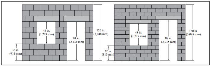
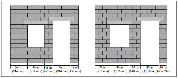
Concrete masonry structures can be constructed using virtually any layout dimension. However, for maximum construction efficiency, economy, and aesthetic benefit, concrete masonry elements should be designed and constructed with modular coordination in mind. Modular coordination is the practice of laying out and dimensioning structures to standard lengths and heights to accommodate modularly-sized building materials.
Standard concrete masonry modules are typically 8 in. (203 mm) vertically and horizontally, but may also include 4-in. (102 mm) modules for some applications. These modules provide the best overall design flexibility and coordination with other building products such as windows and doors. Designing a concrete masonry building to a 4- or 8-in. (102- or 203-mm) module will minimize the number of units that need to be cut, providing a more harmonious looking masonry structure. TEK 05-12, Modular Layout of Concrete Masonry (ref. 10) provides details of modular wall layouts and openings.
CONTROL JOINTS
Control joints, a type of movement joint, are one method used to relieve horizontal tensile stresses due to shrinkage of concrete products and materials. They are essentially vertical planes of weakness built into the wall to reduce restraint and permit longitudinal movement due to anticipated shrinkage. When control joints are required, concrete masonry requires only vertical control joints. When materials with different movement properties are used in the same wythe (such as clay masonry and concrete masonry), this movement difference needs to be accommodated, and may require horizontal movement joints as well (see the Banding section, below). Recommendations for band in a split-faced wall (see Figure 5); with different unit sizes, such as the use of a 4-in. (102-mm) high band in a wall of 8-in. (203-mm) units; or with a combination of these techniques. Combining masonry units of different size, color and finish provides a virtually limitless palette.

The use of concrete masonry bands in clay brick veneer has also become very popular. The architectural effect is very pleasing; however, proper detailing must be provided to accommodate the different movement properties of the two materials to prevent racking. The detail shown in Figure 6 has demonstrated good performance in many areas of the United States and is the preferred detail, as it is economical and maintenance free. Horizontal joint reinforcement is placed in the mortar joints above and below the band, as well as in the band itself if it is more than two courses high. In addition, lateral support (wall ties) are provided within 12 in. (305 mm) of the top and bottom of the band and the band itself must contain at least one row of ties. Some designers prefer placing joint reinforcement in every bed joint of the concrete masonry band. In this case, a tie which accommodates both the tie and reinforcement in the same joint (such as seismic clips) should be used. Another, but less recommended, option is to use horizontal slip planes between clay masonry and the concrete masonry band (see TEK 05-02A, Clay and Concrete Masonry Banding Details, Reference 12).
The maximum spacing of expansion joints in the clay masonry wall should be reduced to no more than 20 ft (6.1 m) when concrete masonry banding is used. When the clay masonry expansion joint spacing exceeds 20 ft (6.1 m), an additional control joint should be placed near mid-panel in the concrete masonry band, although the joint reinforcement should not be cut in this location. At locations control joint spacing, locations and construction details can be found in CMU-TEC-009-23, Crack Control Strategies for Concrete Masonry Construction (ref. 11).
Aesthetically, control joints typically appear as continuous vertical lines in the field of the masonry walls, and perhaps at other areas of stress concentration, such as adjacent to openings, at changes in wall height, etc. Several strategies can be used to make control joints less noticeable. Perhaps the simplest approach is to align the control joint with another architectural feature, such as a pilaster or recess in the wall. In this case, the vertical shadow line provided by the architectural feature provides an inconspicuous control joint location.

BANDING
Concrete masonry banding is successfully used in many architectural applications. Banding can be accomplished with different colors of block; with different textures, for example a smooth-faced of expansion joints in the clay masonry, joints should be continued through the concrete masonry band and the joint reinforcement cut at these locations. TEK 05-02A provides a fuller discussion and additional details for combining these two materials, including details for incorporating clay masonry bands into concrete masonry walls.

LIGHTING DESIGN CONSIDERATIONS FOR CONCRETE MASONRY WALLS
Masonry has historically been associated with diffuse illumination located on or recessed into ceilings, as step (walkway) fixtures located below the waist, or generally placed at a distance from the masonry wall assembly. Diffuse lighting does not concentrate a focused beam but rather spreads the light to provide soft illumination. Although this is sometimes accomplished using an array of many individual light sources at a distance, it is more typically accomplished with fixtures and devices made for this purpose. When wall-mounted light sources are necessary, there are specialized fixtures adapted for masonry that internally refract, reflect, deflect, partially block, diffuse, and/or shade light from directly impinging on the wall surface. Often, the fixture includes additional light diffusers facing away from the wall surface to assist in softly lighting the adjacent area. No noticeable shadows are cast onto the wall, because the shadow is intentionally located away from the wall surface, thus masonry aesthetics are enhanced with a lower lighting intensity and more graceful illumination. These concepts are illustrated in Figure 7.
Non-diffuse light shining onto a concrete masonry wall from a surface mounted light fixture or sconce can sometimes cast unwanted long shadows, giving the erroneous visual appearance of unacceptably poor materials or workmanship (see Figure 7). With non-diffuse light, glossy surface treatments and coatings could also inadvertently magnify this problem. Well-designed diffuse light can eliminate such concerns.
Certain concrete masonry units, such as ground face (also called honed or burnished), can be highly reflective. Figure 8 shows a residential project using a custom-fabricated white ground face block. The designer used a complementary balance of several lighting fixtures with what might have otherwise been a challenging masonry reflective finish. The harmonious use of interior lighting combined with exterior overhead (recessed trim) and step lighting is an effective way of solving this challenge.

REFERENCES
- Cleaning Concrete Masonry, TEK 08-04A. Concrete Masonry & Hardscapes Association, 2005.
- Concrete Masonry Unit Shapes, Sizes, Properties, and Specifications, CMU-TEC-001-23, Concrete Masonry &
Hardscapes Association, 2023. - Standard Specification for Loadbearing Concrete Masonry Units, ASTM C90-09. ASTM International, 2009.
- Water Repellents for Concrete Masonry Walls, TEK 19-01.
Concrete Masonry & Hardscapes Association, 2006. - J. A. Farney, Melander, J. M., and Panarese, W. C., Concrete Masonry Handbook for Architects, Engineers, Builders, Sixth Edition, Engineering Bulletin 008. Portland Cement Association, 2008.
- International Building Code, International Code Council, 2009.
- Specification for Masonry Structures, TMS 602/ACI 530.1/ASCE 6. Reported by the Masonry Standards Joint Committee, 2008.
- Standard Specification for Aggregate for Masonry Mortar, ASTM C144-04. ASTM International, 2004.
- Concrete Masonry Construction, TEK 03-08A. Concrete Masonry & Hardscapes Association, 2001.
- Modular Layout of Concrete Masonry, TEK 05-12. Concrete Masonry & Hardscapes Association, 2008.
- Crack Control Strategies for Concrete Masonry Construction, CMU-TEC-009-23, Concrete Masonry & Hardscapes Association, 2023.
- Clay and Concrete Masonry Banding Details, TEK 05-02A.
Concrete Masonry & Hardscapes Association, 2002.