Resources

Characteristics of Concrete Masonry Units With Integral Water Repellent

INTRODUCTION

A concrete masonry unit’s characteristics are a function of the properties and proportions of the materials used, as well as the manufacturing processes. The unit characteristics do not singularly define the characteristics and performance attributes of a concrete masonry wall, but they certainly play a significant role in influencing those attributes. When used as part of a breathable exterior wall for an inhabited structure, or as a barrier for any conditioned or protected space, concrete masonry is expected to contribute to the water penetration resistance and moisture control of the wall assembly. Current model building codes include provisions intended to ensure that exterior walls provide adequate weather protection for the building (ref. 1).

Design of concrete masonry walls to mitigate or control moisture migration includes many considerations beyond the characteristics of the concrete masonry unit, such as flashing, weeps, workmanship, mortar or grout characteristics, vents, coatings, vapor barriers, air barriers, temperature differences, and accommodation of differential movement, plumbing and roof leaks, as well as other considerations. The potential for condensation, whether at the wall’s interior surface, weather-exposed surface, and/or interior of the wall, should also be considered. Proper design and construction of concrete masonry, considering all of these elements, is critical to the water resistant performance of the wall system. These topics are addressed in References 2 through 7 and in other literature sources.

Mortar joints are especially critical to a wall’s water penetration resistance. Achieving good bond between the mortar and the unit surfaces is essential and is largely influenced by the mortar material itself, tooling procedures, and joint profile as well as by the configuration of the concrete masonry unit. Ribbed units, for example, make it difficult to adequately tool the mortar joints. Reducing mortar’s absorption characteristic is also important for achieving success in moisture control in a concrete masonry wall. This can be achieved using integral water repellent admixtures in the preparation of the mortar.

While all of the aforementioned aspects significantly affect wall performance, this TEK focuses specifically on evaluating the water penetration resistance characteristics of concrete masonry units and their role in contributing to control of moisture in the wall.

THE ROLE OF CONCRETE MASONRY UNITS

The concrete masonry unit’s role and contribution to the concrete masonry wall assembly’s water penetration resistance depends in part on how the units are used in the design. The unit characteristic requirements for contributing to success of the exterior wall may vary depending on the design of the masonry wall in which it is used. For example, the role of concrete masonry units is more critical relative to moisture control when they are part of a weather-exposed surface or exterior wall assembly for a protected and conditioned building than if they are used as an interior wall.

There are three primary forces influencing moisture control of a concrete masonry wall: positive or negative air pressures created by the weather or building ventilation systems, internal moisture absorption and/or adsorption through the matrix of the concrete material, and condensation/evaporation. For the purposes of this discussion, absorption is considered to relate to the cementitious material’s attraction to or affinity for water at the molecular level. Generally speaking, mortar tends to have a much greater affinity for water than does a concrete masonry unit. Adsorption is the affinity of water at the individual surfaces of the cementitious materials. For instance, capillary pressure creates the tendency for water to migrate into a porous object along the surfaces of the interconnected voids, such as a sponge placed in very shallow water. The same tendency may be observed in a mortar joint or an untreated concrete masonry unit due to interconnected voids.

When units are used on a building exterior, it is desirable to limit moisture migration through the first barrier of defense at the wall surface. Wind driven rain can be a significant cause of water breaching a mortar joint, the front face shell of a single wythe wall, or a veneer unit. These weather-induced positive pressures can create a challenge to barrier defenses. As a driving force, they are highest at the surface of the masonry and rapidly diminish a few inches into the mortar joint, the unit, or into the cavity of a drainage wall.

Water repellency characteristics of concrete masonry units can be defined by their contribution to barrier defenses at the surface of the wall (which will help limit the effect of the positive pressure of wind driven rain), by their ability to limit the potential for absorbing and adsorbing moisture through their matrix, and by their contribution to controlling condensation.

PERTINENT UNIT CHARACTERISTICS

Barrier defenses in concrete masonry units can be provided at the surface as well as within the mass of the concrete layer. Surface protection can be enhanced by post-applied breathable materials, external coatings and wall coverings. When coatings are used, the most important characteristic of the unit may be its compatibility with the type of coating used. Some clear sealers and certain paints may not be suitable for a particular concrete masonry unit since some coatings may not be able to bridge open pores or fill all surface irregularities or textures. For example, the proper performance of stucco relies on a rougher and more open unit surface texture of the concrete masonry unit to ensure adequate mechanical bonding.

Beyond the unit’s exterior surface compatibility with the type of breathable post-applied material, coating or wall covering used, if any, an important consideration is the characteristics of the concrete used to produce the unit. The water penetration resistance of concrete is determined by the characteristics of the matrix and its resistance to absorbing moisture. The properties and proportions of the raw materials used to produce the units and the manufacturing procedures employed influence the water penetration resistance of those units. For example, a greater volume of interconnected voids within the unit may provide an easier path for moisture migration. Alternatively, reducing the volume of voids, such as by increasing the unit compaction, may limit moisture movement through the unit. Aggregate type and gradation, cement to aggregate ratio, mix water content, alkalinity, machine compaction, curing processes, and plasticizing and integral water repellent admixtures are some of the parameters that can have an influence on water repellency characteristics.

INTEGRAL WATER REPELLENTS

Integral water repellent admixtures can be used in the mix design of the concrete masonry unit during production to limit a unit’s tendency to absorb moisture through its matrix. Integral water repellent admixtures are usually polymeric products that utilize hydrophobic materials to significantly reduce the absorption characteristics of the concrete. Without these admixtures, even those units with excellent compaction will absorb some moisture through the concrete matrix. Integral water repellents significantly limit absorption by changing the chemistry of the matrix, which may include coating the pores in the concrete with a hydrophobic material that reduces the chemical affinity for water. Thus, concrete masonry units with integral water repellents are positioned to repel water rather than automatically allowing it to migrate through the unit. However, use of integral water repellent admixtures alone does not assure a water-resistant unit. Care must still be taken in production as discussed above to reduce the volume of interconnected voids that will permit moisture migration via other forces, such as wind or gravity.

An advantage of integral water repellent admixtures is that they remain a permanent part of the concrete matrix. Unlike post-applied products, integral water repellent treatments require less maintenance since they are more durable, and they are active throughout the whole concrete matrix and not just at the surface. In addition, integral water repellents can reduce efflorescence by reducing water migration through the concrete masonry (including latent water introduced to the system from grout or mortar).

When integral water repellents are used in concrete masonry units, it is important that the same or a compatible admixture be used in the mortar as well in accordance with manufacturer’s recommendations. Failure to use an integral water repellent admixture in the mortar may compromise the water repellency characteristics of the wall.

EVALUATING UNIT WATER REPELLENCY

The water repellency characteristics of a concrete masonry unit can be evaluated using simplistic field methods or more involved laboratory test methods. Three methods are described briefly below, and in more detail in the referenced published industry test methods (refs. 8, 9, 10).

All of these tests are suitable for evaluating units to be used in wall construction. It is important that field testing, if considered necessary, be conducted prior to wall construction since most of these tests can not be accurately performed on a constructed wall surface. For instance, small amounts of mortar left on the surface of a unit even after cleaning, as well as the cleaning techniques themselves, may alter the surface characteristics of the unit relative to its as-delivered condition. Similarly, water introduced into the system from grout or mortar (water of latency) and in turn absorbed into the unit may change the unit’s characteristics. Before, after, or during construction, accumulated dust or pollution may also alter the surface characteristics. When water repellency characteristics are evaluated prior to unit placement, any unexpected results from field testing can be addressed in a timely manner using the default laboratory test methods described below.

Water Bottle and Water Droplet Tests

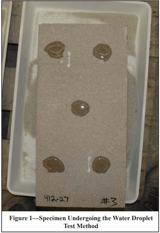
The water bottle and water droplet test methods (ref. 8) can be effective as a first pass evaluations of water repellency. The water droplet method is typically conducted on individual units in a horizontal position as shown in Figure 1 (90 degrees to the “as laid” or construction orientation), but as a variation the water bottle test can also be conducted on units placed in a vertical (“as laid”) orientation. Typically, a concrete masonry unit manufactured with an integral water-repellent admixture will be able to support at least three out of the five water droplets for a period of five minutes or more.

At the immediate surface of the concrete masonry unit, the effectiveness of an integral water repellent may diminish over time due to exposure to elements such as dirt, contaminants and UV light. The water repellency characteristics of the concrete just below the surface, however, remain unchanged and provide continuing protection. Therefore, while the water droplet test is rather reliable for identifying a sufficient level of water repellency, it may not be a good indicator of poor water repellency. In other words, if a unit fails to support a droplet of water, the unit should not be considered inadequate, but rather should be taken to a laboratory for further testing using the spray bar and water uptake methods.

If the unit is already installed in the wall, the water bottle test can be used to evaluate the unit. If water applied to the face of the unit is not absorbed immediately, but rather freely runs down the surface of the unit, it likely has sufficient water repellency. Again, if the water is absorbed at the surface, it can not be assumed that the unit does not have sufficient water resistance. Water can be sprayed on a larger wall surface area to determine if isolated units appear to have significantly higher absorption characteristics, since these may appear to have a darker surface color as a result of absorbed water. However, remember that conclusions based upon any field testing, especially on units installed in construction, are not definitive relative to water repellency determinations.

Spray Bar Test

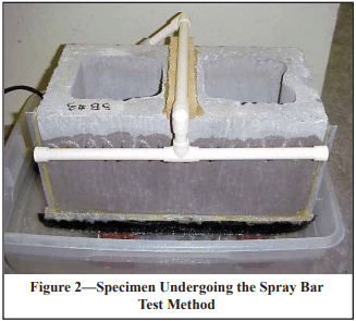
A spray bar test (ref. 9) is a good method to evaluate a unit’s ability to limit absorption as well as verify its effectiveness as a barrier against free moisture migrating through pinholes in the unit face. This laboratory test requires relatively inexpensive equipment and can be conducted in a single day. A spray bar is attached to the unit such that it applies a steady stream of water onto its face (see Figure 2). The inside of a hollow unit is visually inspected to assess if and how moisture has migrated through the front face shell.

Moisture may be present on the interior as dampness that can be seen on the inside surface of the front face shell, on the center or end webs, or even on the interior or exterior surfaces of the back face shell. Moisture may also be observed on the inside of the front face shell from “pinholes.” Pinholes are locations where water has found a path through the face shell to the interior of the unit. Free water will appear as a droplet and may eventually trickle down the inside of the front face shell. A good water repellent unit will limit moisture migration in both forms: dampness and pinholes. If a unit allows an excessive amount of water to migrate through the unit, the type of failure can give an indication of the corrective action that should be taken by the producer. Excessive dampness, for example, may indicate that additional integral water repellent admixture or process adjustment is needed. Excessive pinholes may indicate that an adjustment to the aggregate blend and/or increased compaction may be necessary to reduce the volume of interconnected voids in the unit.

Water Uptake Test

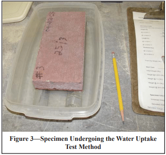
Another good method for evaluating a unit’s resistance to moisture migration is the water uptake test (ref. 10). The test involves placing an oven-dried unit face down (non-split side) in in. (3 mm) of water and measuring the water absorption by means of its weight gain over time.

While the water uptake test may be very good at distinguishing between the levels of resistance to absorption uptake, it will not indicate compaction or other flaws that might result in pinholes. Therefore, it is recommended that the results of this test be used to complement the results of the spray bar test and not used exclusively as a means of evaluation.

REFERENCES

  1. International Building Code, 2003 and 2006 editions. International Code Council, 2003, 2006.
  2. Water Repellents for Concrete Masonry Walls, TEK 19-01, Concrete Masonry & Hardscapes Association, 2006.
  3. Design for Dry Single-Wythe Concrete Masonry Walls, TEK 19-02B, Concrete Masonry & Hardscapes Association, 2012.
  4. Preventing Water Penetration in Below-Grade CM Walls, TEK 19-03B, Concrete Masonry & Hardscapes Association, 2012.
  5. Flashing Strategies for Concrete Masonry Walls, TEK 19-04A, Concrete Masonry & Hardscapes Association, 2008.
  6. Flashing Details for Concrete Masonry Walls, TEK 19-05A, Concrete Masonry & Hardscapes Association, 2008.
  7. Crack Control Strategies for Concrete Masonry Construction, CMU-TEC-009-23, Concrete Masonry & Hardscapes Association, 2023.
  8. Water Droplet Test Method for Concrete Masonry Units, CMHA Method CMU-WR1-07, Concrete Masonry & Hardscapes Association, 2007.
  9. Spray Bar Test Method for Concrete Masonry Units, CMHA Method CMU-WR2-07, Concrete Masonry & Hardscapes Association, 2007.
  10. Water Uptake Test Method for Concrete Masonry Units, CMHA Method CMU-WR3-07, Concrete Masonry & Hardscapes Association, 2007.
  11. Standard Specification for Loadbearing Concrete Masonry Units, ASTM C 90-06. ASTM International, 2006.
  12. Standard Specification for Concrete Facing Brick, ASTM C 1634-06. ASTM International, 2006.

NCMA and the companies disseminating this technical information disclaim any and all responsibility and liability for the accuracy and the application of the information contained in this publication.
Flashing Details for Concrete Masonry Walls

INTRODUCTION

At critical locations throughout a building, moisture that manages to penetrate a wall is collected and diverted to the outside by means of flashing. The type of flashing and its installation may vary depending upon exposure conditions, opening types, locations and wall types. This TEK includes typical flashing details that have proven effective over a wide geographical range. The reader is also encouraged to review the companion TEK 19-04A Flashing Strategies for Concrete Masonry Walls (ref. 1) which addresses the effect of moisture on masonry, design considerations, flashing materials, construction practices, and maintenance of flashing.

CAVITY WALLS

For cavity walls, as illustrated in Figure 1, the cavity typically ranges from a minimum of 2 in. to a maximum of 4 ½ in. (25 to 114 mm) wide, with a minimum of a 1 in. (25 mm) clear airspace if rigid insulation is placed in the cavity. Cavities wider than 4 ½ in. (114 mm) are permitted only if a detailed analysis is performed on the wall ties per the International Building Code and Building Code Requirements of Masonry Structures (refs. 2, 3) The 1 in. (25 mm) clear airspace works only if the mason takes precautions to insure that mortar will not bridge the airspace. Such precautions would include beveling the mortar bed away from the cavity or drawing a piece of wood up the cavity to collect mortar droppings. If precautions are not taken, it is suggested that a wider airspace be utilized, i.e. 1½ to 2 in (38 to 51 mm). Also when using glazed masonry veneer, a 2 in. (51 mm) minimum airspace is recommended with air vents provided at the top and bottom of the wall because of the impermeable nature of the unit. Proprietary insulated drainage boards or mats are available that provide an unobstructed drainage path that eliminate the need for a clear airspace (ref. 4).

As shown in Figure 1, the flashing in a cavity wall at the intersection of the foundation should be sealed to the exterior faceshell of the backup wythe, project downward to the foundation surface, outward to the exterior face of the wall, and terminate with a sloped drip. Weep holes or open head joints should be located a maximum of 32 in. (813 mm) apart. Flashing at lintels and sills (shown in Figures 2 and 3, respectively) is very similar. Although not shown, vents can be installed in the vertical head joints at the top of masonry walls to provide natural convective air flow within the cavity to facilitate drying. Prefabricated flashing boots available for both single and multiwythe walls are shown in Figure 7.

SINGLE WYTHE WALLS

Flashings in single wythe walls, like cavity walls should be positioned to direct water to the exterior. This is normally accomplished using two narrower units to make up the thickness of the wall and placing flashing between them as shown in Figures 4 and 8. Care should be exercised to insure that surfaces supporting the flashing are flat or are sloping to the exterior. This can be accomplished by using solid units, lintel or closed bottom bond beam units turned upside down similar to Figure 3, or by filling cells of hollow units with mortar or grout.

Flashing of single wythe walls at lintels, foundations, and bond beams is accomplished in the same manner as shown in Figure 4 while sills are shown in Figure 6. Through-wall flashing is used in many areas of the country as shown in Figure 9. However, the bondbreaking effects of this type of detail need to be evaluated in regard to the structural performance of the wall. Additional information for flashing single-wythe walls, particularly architectural concrete masonry walls, and means for providing a higher level of structural continuity at flashings is contained in TEK 19-02B (ref. 5). Flashing single wythe walls at the ends of bar joists which utilize wall pockets for bearing is shown in Figures 8 and 8a.

FLASHINGS AT COPINGS AND CAPS

The type of flashing detail to use on low-sloped roofs will in part depend on the type of roofing membrane being used. As with any flashing detail, the materials used should result in a uniform and compatible design. For example, joining two materials with significantly different coefficients of thermal expansion (such as metal flashing and bitumen roofing membrane) can cause tearing and failure of the joint. Many roofing membranes also shrink as they age. As a result, roofing membranes extending over the top of a parapet may pull the parapet off the wall as the roofing membrane shrinks. Counter flashing provides a solution to these problems as shown in Figure 8. Counter flashing also facilitates the reroofing process by allowing easy removal and access to the flashing membrane fasteners.

During placement of the final courses of masonry in parapets, and commencing with the second course below the coping/cap location, a grout stop should be placed over cores so that grout can be placed for the positioning of anchor bolts (Figure 8).

In coping installations it is imperative that penetrations of through-wall flashing be tightly sealed to prevent water infiltration. A full mortar bed is required to be placed on the through-wall flashing to allow proper positioning of coping units. Full head joints are placed between the coping units as well as properly spaced control joints. The joints between the coping units should then be raked and a joint sealant applied.

Coping units should be sized such that overhangs and a drip reveal are provided on both sides of the wall. Metal caps require wood plates for anchorage, which in turn are usually attached to the wall with anchor bolts. The cap should be sloped to prevent water from draining onto the exposed surface of the masonry and should extend at least 4 in. (102 mm) over the face of the masonry and sealed on both sides. Smooth face or uniform split face CMU should be considered for use under the cap to ensure a relatively tight fit between the masonry and cap that might be hindered by uneven concrete masonry units such as split-face or fluted units.

INTERIOR WALL TREATMENTS

Concrete masonry walls with an interior treatment may also utilize a through-wall flashing installation of flashings as shown in Figure 9. However, as noted in the figure, through-wall flashings generally create a bond-breaker, which reduces the structural capacity of a masonry wall. This effect should be carefully evaluated before implementing this type of detail particularly in high-wind and seismic areas.

As shown in Figure 9, the flashing should project through the wall and be carried up on the interior concrete masonry surface. Furring strips installed to receive the plastic vapor retarder and the interior gypsum board will hold the flashing in position. This procedure permits any water that may penetrate to the interior surface of the concrete masonry wall to drain out at the base of the wall. Weep holes should project completely through the wall thickness. Vents, if used, should project into the core areas only.

SPLICING FLASHING

When it is necessary to splice the flashing, extra precautions are required to ensure that these discreet locations do not become sources of water penetration. Flashing should be longitudinally continuous or terminated with an end dam as shown in Figure 7. The splicing of flashing materials consisting of plastic and rubber compounds is acheived by overlapping the joint a minimum distance of 4 in. (102 mm). The lapped area is then bonded together with adhesive if the flashing material is not self-adhering.

Lap splicing of metal flashing is not recommended as it has a different coefficient of thermal expansion than that of concrete masonry. As the temperature fluctuates, the flashing material will expand and contract differently than the masonry material, which can result in sealant failure and a potential point of entry for moisture. A typical flashing splice is detailed in Figure 10. Here, two sections of sheet metal type flashing that are to be spliced are first installed with a ¼-in. (6.4 mm) gap between them to allow for expansion of the flashing. Next, a section of pliable self-adhering membrane (such as rubberized-asphalt) or other pliable membrane set in mastic is fully bonded to the flashing at the location of the gap.

REFERENCES

  1. Flashing Strategies for Concrete Masonry Walls, TEK 1904A, Concrete Masonry & Hardscapes Association, 2008.
  2. International Building Code. International Code Council, 2003 and 2006.
  3. Building Code Requirements for Masonry Structures, ACI 530/ASCE 5/TMS 402, reported by the Masonry Standards Joint Committee, 2002 and 2005.
  4. Flashing…Tying the Loose Ends, Masonry Advisory Council, Chicago, IL, 1998.
  5. Design for Dry Single-Wythe Concrete Masonry Walls, TEK 19-02B, Concrete Masonry & Hardscapes Association, 2012.
  6. Generic Wall Design, Masonry Institute of Michigan, 1998.


Flashing Strategies for Concrete Masonry Walls

INTRODUCTION

The primary role of flashing is to intercept the flow of moisture through masonry and direct it to the exterior of the structure. Due to the abundant sources of moisture and the potentially detrimental effects it can have, the choice of flashing material, and the design and construction of flashing details, can often be as key to the performance of a masonry structure as that of the structural system.

The type of flashing material to be used is governed by both environmental and design/build considerations. Environmental considerations include such factors as the physical state of moisture present (liquid, solid, or vapor), air movement, and temperature extremes as well as temperature differentials. Design/build considerations include the selection of the proper type of flashing material, location of the flashing, structural, and installation details. Drawings for flashing details, often the only method of communicating the necessary information between the designer and contractor, should be comprehensive and show sufficient detail for the proper interpretation and installation of flashing systems. TEK 19-05A Flashing Details for Concrete Masonry Walls (ref. 3) includes such details.

Although flashing is the primary focus of this TEK, it should be understood that the role of vapor retarders, air barriers, and insulation are also important elements to consider for any wall design as the performance of the entire system can be dependent on the design of its individual components.

EFFECT OF MOISTURE ON MASONRY

The damage caused to a masonry structure (or its contents) due to the infiltration of moisture can take many forms, depending on the source and the physical state of the water. For example, in the liquid state, water penetrating to the interior of a building may cause considerable damage to its contents. In some extreme cases, water trapped within the masonry may freeze, inducing spalling and cracking of the masonry units or mortar. Alternatively, water vapor can lead to condensation inside the cores and on the surfaces of masonry if the dew point temperature is reached. During cold weather, below 28 °F (-2 °C), water vapor can accumulate on a cold surface and form frost or increase the quantity of ice within the masonry.

Although it is commonly thought that moisture problems stem only from the external environment, this is not always the case. For example, in some instances it is possible for the humidity of interior air to cause water damage to the exterior of a structure. This damage may appear in the form of water stains, ravelled mortar joints, spalled surfaces, or efflorescence.

DESIGN CONSIDERATIONS

Water Movement

In the design of any structure, the presence and movement of water in any of its three forms needs to be considered. Significant forces that influence water movement include wind pressure, gravity, and moisture absorption by the material. Dynamic wind pressure on the surface of an exposed wall can drive exterior moisture (in the form of rain or irrigation water) into the masonry. Gravity, which is always present, draws the free water vertically downward, while the absorptive characteristics of the masonry can cause moisture migration in any direction by capillary action.

It should also be recognized that these forces do not act independently of one another. For example, wind-driven rain may enter masonry through cracks at the interface between mortar and units and migrate downward through the wall due to the force of gravity, or it may be transferred horizontally through the wall either by pressure or by flowing across the webs of the units or mortar bridges. Wind-driven rain can also be absorbed by masonry units and carried from the exterior surface to the interior surface by capillary action. Additionally, ground water may be drawn upward by the wicking action of units placed on porous foundations or by contact with moist soil.

Designers should never assume that any material is capable of rendering a wall totally impervious to water penetration. Surface treatments, designed to reduce the quantity of water entering a masonry structure, are helpful in this regard but should not be considered as a sole means of protection. Available as clear and opaque compounds, the effectiveness of surface treatments depends on their composition and compatibility with the masonry. They also do not reduce the movement by capillary action (wicking) of any water that does penetrate the masonry face through cracks or defects in the mortar/masonry.

The use of integral water repellent admixtures in concrete masonry units and mortars can also reduce the amount of water entering the masonry. In addition, they inhibit water penetrating the masonry face from wicking to the back face of the wall.

Proper selection and application of surface treatments and integral water repellents can greatly enhance the water resistant properties of masonry, but they should not be considered as substitutes for flashing. See TEKs 19-01 and 19-02B (refs. 8 and 2) for more information on water repellents for concrete masonry.

Flashing Location

The proper design of masonry for resistance to water penetration includes consideration of the various types of wall construction such as single wythe, cavity, veneer, etc. During the design phase it should be understood that all exterior masonry walls may be subjected to some degree of water penetration and/or water vapor movement during its design life. Flashing is recommended for all locations where moisture may potentially penetrate into a wall and where the free drainage of water is blocked. Some of these critical locations include the top of walls and parapets, at all horizontal obstructions such as over openings, beneath sills, above shelf angles, at the base of walls, and in walls at ground level to serve as a moisture retarder to reduce the amount of water wicked up into the masonry above grade.

When selecting the flashing material for a particular application, the service conditions, projected life of the structure, and past performance characteristics of the flashing materials should be reviewed. Flashing should be designed to perform satisfactorily for the design life of the building since repair or replacement can be very labor intensive and expensive.

FLASHING MATERIALS

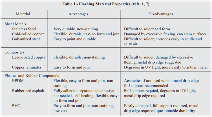
A wide variety of flashing materials are available. The selection of the type of flashing material to use can be influenced by several factors including cost, durability, compatibility with other materials, ease of installation, aesthetic value, and performance. Table 1 summarizes some of the attributes for various flashing materials. The advantages and disadvantages of each must be weighed for each individual project to provide the most cost-effective and desirable choice.

Prefabricated flashing boots may be available for inside and outside corners and end dams. These boots eliminate the need for cutting, folding, or tucking the flashing materials at these locations. However, due to construction tolerances, some of these prefabricated items, particularly those of rigid materials, may be difficult to fit into their intended location.

Sheet Metals

Stainless steel is technically any of a large and complex group of corrosion resistant iron chromium alloys possessing excellent weather and chemical resisting properties. Preformed sections must be properly sized so that on site modification is minimized. Stainless steel flashing with a conventional annealed finish should comply with Standard Specification for Stainless and Heat-Resisting Chromium-Nickel Steel Plate, Sheet, and Strip, ASTM A 167 (ref. 6). Generally, Type 304 stainless steel with a minimum thickness of 0.010 in. (0.25 mm) is satisfactory. Lap sections require solder conforming to Standard Specification for Solder Metal, ASTM B 32 (60% tin and 40% lead) (ref. 5). Stainless steel drip edges used in combination with other flashing materials offer an economical compromise with a durable drip edge.

Copper is a nonferrous metal possessing good ductility and malleability characteristics. Like stainless steel, it also possesses excellent weather and chemical resistant properties. Preformed sections or sheet materials are easily modified to conform to site requirements. However, it should be cautioned that once weathered, copper flashings produce a green patina that may impart a green stain to adjacent masonry surfaces that some find objectionable.

Galvanized steel is less expensive than stainless steel but is subject to corrosive attack from salts and acids. The galvanized coating also may crack at bends, lowering the corrosion resistance. As with stainless steel, it is also difficult to form and to solder laps effectively.

Composites

Combinations of metals and plastics are supplied by some dealers. The composition and application of these combined materials should be determined before use. Composites utilizing copper are the most popular since they combine the durability and malleability of copper with the nonstaining characteristics of a protective coating. Composites containing aluminum should be avoided.

Plastics and Rubber Compounds

Plastics are categorized as polymeric materials of large molecular weight, usually polyvinyl chloride (PVC) or polyethylene. Manufacturers of plastic flashings should be consulted for documentation establishing the longevity of the plastic in a caustic environment (pH = 12.5 to 13.5), the composition of the plastic, ease of working at temperatures ranging from 20 to 100 °F (-7 to 38 °C), and ability to withstand exposure to ultraviolet light.

Ethylene Propylene Diene Monomer (EPDM) is a synthetic rubber that is used as a single ply roofing membrane as well as flashing. It has better low temperature performance than PVC and will not embrittle. It offers ultraviolet light and ozone resistance and can be left exposed.

Self-adhering, rubberized asphalt membranes consist of a composite of flexible plastic film for puncture and tear resistance combined with a rubberized asphalt adhesive layer. This material adheres to itself, requiring less effort to seal laps or corners which speeds installation. It also self-adheres to the substrate which prevents water from migrating under the flashing and is self-healing in the event of punctures. However, it should not be applied to damp, dirty, or dusty surfaces and typically has a lower installation temperature limit of 25 °F (-4 °C). Because it degrades in the presence of extended UV exposure, it should not be left exposed and requires a metal drip edge.

CONSTRUCTION PRACTICES

To perform, flashing must be designed and installed properly or it may aggravate rather than reduce water problems. Flashing should be longitudinally continuous or terminated with end dams. Longitudinally continuous requires that joints be overlapped sufficiently, 4 in. (102 mm) minimum, to prevent moisture from entering between the joints and they must be bonded (joined) together with adhesive if they are not self adhering to prevent water movement through the lap area. With metal flashings a ¼ in. (6.4 mm) gap joined and sealed with a pliable membrane helps in accommodating expansion (ref. 3).

Flashings should be secured at the top by embedment into the masonry, a reglet, or should be adhesively attached so that water cannot infiltrate or move behind the attachment. For multi-wythe construction, the flashing should project downward along the outer surface of the inner wythe and then project outward at the masonry joint, shelf angle, or lintel where it is to discharge the water. Every effort should be made to slope the flashing towards the exterior. Effectively placed mortar or sealant material can help promote this drainage. The flashing should continue beyond the exterior face of the masonry a minimum of ¼ in. (6.4 mm) and terminate with a sloped drip edge.

An additional design consideration for flashings includes ensuring that all materials are compatible. For example, contact between dissimilar metals can result in the corrosion of one or both of the metals. Additionally, the coefficients of thermal expansion for the flashing and masonry materials differ. All flashing details should be designed to accommodate the resulting differential movement.

Other recommended practices involve the use of tooled concave mortar joints to reduce water penetration through the mortar joints. Masons should be careful to ensure that mortar dropped onto the flashing is minimized. This can be accomplished by beveling the mortar on the face shells adjacent to the cavities in cavity wall construction. In addition, cavity drainage mats, gravel beds, screens, or trapezoidal drainage material (filter paper) can be used to prevent mortar droppings from collecting on the flashing, which can form dams and block weep holes. Mortar collection devices at regular intervals or filling the cells with loose fill insulation a few courses at a time as the wall is laid-up, can be effective in dispersing minor mortar droppings enough to prevent clogging.

Weep holes, the inseparable companion to flashings, should provide free movement of water out of the concrete masonry cores, collar joints, or cavities. Any construction practice that allows forming the weep holes without inhibiting water flow may be used. Cotton sash cords and partially open head joints are the most common types of weep holes. Cotton sash cords should be removed prior to putting the wall into service to provide maximum unobstructed drainage. If necessary, insects can be thwarted by inserting stainless steel wool into the openings or using plastic or metal vents.

Vents

Weep holes often serve a dual function, first for water drainage and second as vents. Vents are desirable in some masonry wall systems to help reduce the moisture content of the masonry during drying periods. Air circulation through the cores and cavities within the masonry promotes equalization of moisture content throughout the masonry. Vents are considered desirable where air is confined within masonry, such as in parapets or areas of high humidity such as natatoriums.

MAINTENANCE

Maintenance programs should involve preserving the “as-built” design documents, records pertaining to inspections during the life of the structure, and continuing appraisal of the performance of the structure in addition to conventional repair and upkeep. Documentation of inspections, if efflorescence and water stains are observed, and logs of reported water penetration and their identified location, assist in determining proper corrective actions. Pictures with imprinted dates are suggested.

Knowledge of the wall design and construction can influence repair decisions. If flashing and weep holes were omitted during construction, it may prove effective to simply drill weep holes and vents to promote drainage and drying. Weep holes so drilled should be either at the intersection of the bed and head joints or into the cores at the bottom of the wall. Vents should be installed at the top of the wall or directly below bond beams. See TEK 08-01A Maintenance of Concrete Masonry Walls (ref. 4) for more detailed information on maintenance of concrete masonry walls.

When considering maintenance options, it is important to ensure that a masonry wall’s moisture control measures are kept intact. Thus, applying sealant beads, pargings, or coatings to a wall should be carefully weighed. Weep holes and vents should be maintained in an open condition to allow evacuation of moisture.

SUMMARY

Flashings are essential at foundations, bond beams, above and below openings, at shelf angles and at copings. Weep holes and vents reduce the moisture content of masonry walls. Proper selection of flashing materials, proper detailing, and proper installation will help ensure satisfactory performance.

REFERENCES

  1. The Building Envelope: Solutions to Problems, Proceedings from a national seminar series sponsored by Simpson Gumpertz & Heger Inc., 1993.
  2. Design for Dry Single-Wythe Concrete Masonry Walls, TEK 19-02B, Concrete Masonry & Hardscapes Association, 2012.
  3. Flashing Details for Concrete Masonry Walls, TEK 19-05A, Concrete Masonry & Hardscapes Association, 2008.
  4. Maintenance of Concrete Masonry Walls, TEK 08-01A, Concrete Masonry & Hardscapes Association, 2004.
  5. Standard Specification for Solder Metal, ASTM B 32-04, ASTM International, 2004.
  6. Standard Specification for Stainless and Heat-Resisting Chromium-Nickel Steel Plate, Sheet, and Strip, ASTM A 167-99(2004), ASTM International, 2004.
  7. Through-Wall Flashing, Engineering and Research Digest No. 654, Brick Industry Association.
  8. Water Repellents for Concrete Masonry Walls, TEK 19-01, Concrete Masonry & Hardscapes Association, 2006.


Preventing Water Penetration in Below-Grade Concrete Masonry Walls

INTRODUCTION

Concrete masonry has traditionally been the material of choice for foundation wall construction. State-of-the-art waterproofing, dampproofing, and drainage systems applied to concrete masonry provide excellent protection from water penetration, ensuring protection for building contents and comfort for occupants.

Protecting below-grade walls from water entry involves installing a barrier to water and water vapor. Below grade moisture tends to migrate from the damp soil to the drier area inside the basement. An impervious barrier on the exterior wall surface can prevent moisture entry. The barrier is part of a comprehensive system to prevent water penetration, which includes proper wall construction and the installation of drains, gutters, and proper grading.

WATERPROOFING AND DAMPPROOFING

Building codes (refs. 1, 2) typically require that basement walls be dampproofed for conditions where hydrostatic pressure will not occur, and waterproofed where hydrostatic pressures may exist. Dampproofing is appropriate where groundwater drainage is good, through granular backfill into a subsoil drainage system.

Hydrostatic pressure may exist due to a high water table or due to poorly draining backfill, such as heavy clay soils. Materials used for waterproofing are generally elastic, allowing them to span small cracks and accommodate minor movements.

When choosing a system, consideration should be given to the degree of resistance to hydrostatic head of water, absorption characteristics, elasticity, stability in moist soil, resistance to mildew and algae, and impact, puncture and abrasion resistance.

WATERPROOF AND DAMPPROOF SYSTEMS

Waterproof and dampproof systems must be continuous to prevent water penetration. Similarly, the barrier is typically carried above the finished grade level to prevent water entry between the barrier and the foundation wall. Cracks exceeding ¼ in. (6 mm) should be repaired before applying a waterproof or dampproof barrier. Repair of hairline cracks is typically not required, as most barriers will either fill or span small openings. In addition, most waterproofing and dampproofing systems should be applied to clean, dry walls. In all cases, manufacturer’s directions should be carefully followed for proper installation.

Particular attention should be paid to wall penetrations and to re-entrant corners at garages, porches, and fireplaces. Because differential movement often occurs at these intersections, stretchable membranes are often used to span any potential cracks. Alternately, the main wall in some cases can be coated prior to constructing the cross wall provided that structural adequacy is maintained.

Coatings are sprayed, trowelled, or brushed onto below-grade walls, providing a continuous barrier to water entry. Coatings should be applied to clean, structurally sound walls. Walls should be brushed or washed to remove dirt, oil, efflorescence, or other materials which may reduce the bond between the coating and the wall.

Sheet membranes and panels are less dependent on workmanship and surface preparation than coatings. Many membrane systems are better able to remain intact in the event of settlement or other foundation wall movement. Seams, terminations, and penetrations must be properly sealed.

Prescriptive Systems

Both the International Building Code (IBC) (ref. 1) and the International Residential Code (IRC) (ref. 2) include prescriptive methods for waterproofing and dampproofing. Except where a damproofing material is approved for direct application to the masonry, masonry walls are required to have not less than in. (9.5 mm) portland cement parging applied to the exterior of the wall before applying damproofing. The following materials are specified in the IBC as acceptable waterproofing and dampproofing materials:

  • two-ply hot-mopped felts;
  • 6 mil (0.006 in.; 0.152 mm) or greater polyvinyl chloride;
  • 40 mil (0.040 in.; 1.02 mm) polymer-modified asphalt;
  • 6 mil (0.006 in.; 0.152 mm) polyethylene; or
  • other approved methods or materials capable of bridging nonstructural cracks.

In addition, the IRC includes the following materials for concrete and masonry foundation waterproofing:

  • 55 pound (25 kg) roll roofing;
  • 60 mil (1.5 mm) flexible polymer cement;
  • in. (3 mm) cement-based, fiber-reinforced, waterproofing coating; or
  • 60 mil (1.5 mm) solvent-free liquid-applied synthetic rubber.

Both the IBC and IRC list the following materials as acceptable for dampproofing only (note—any of the waterproofing materials are acceptable for dampproofing):

  • bituminous material;
  • 3 lb/yd² (16 N/m²) of acrylic modified cement;
  • in. (3.2 mm) coat of surface-bonding mortar complying with ASTM C887 (ref. 3); or
  • other approved methods or materials.

The following discusses details of some of the prescriptive code methods for waterproofing and dampproofing.

Rubberized Asphalt Systems

A wide variety of rubberized and other polymer-modified asphalt waterproofing systems are available. Most of these are applied as sheet membranes, although some are available as liquid coatings. These systems provide a continuous barrier to water with the ability to elastically span small holes or cracks.

Rubberized asphalt sheet membranes are applied over a primer, which is used to increase adhesion of the sheet. The membrane is adhesive on one side and protected by a polyethylene film on the other. Adjacent pieces of membrane must be lapped, and the top and bottom edges sealed with mastic to provide continuous protection from water entry. After the membrane is placed on the wall, the surface is rolled with sufficient pressure to ensure adequate adhesion.

Rubberized asphalt is also available in a form that can be melted at the jobsite, then spread to completely cover foundation walls. Liquid coatings can be applied by airless spray, roller, or brush. Both the liquid-applied and sheets are covered with a protection board, which protects from construction traffic and during backfilling.

Cementitious Coating Systems

Cement-based coatings are typically trowelled onto concrete masonry walls or brushed on using a coarse-fibered brush. The coatings sufficiently fill block pores, small cracks, and irregularities. Some cementitious coatings are modified with various polymers to increase elasticity and water penetration resistance.

Elastomeric Systems

Elastomeric materials are acrylic-based products which provide a flexible barrier to water penetration for below grade walls. Elastomerics are available as liquid coatings and as sheet membranes. The sheets are attached with adhesive, and may be reinforced with fabric to further increase tensile strength and resistance to tears and punctures. Liquid coatings can be applied by airless spray, roller, or brush.

Other Waterproofing and Dampproofing Systems

The systems listed above (and within the building codes) are only some of the materials and systems available; several others are discussed below. See Basement Manual—Design & Construction Using Concrete Masonry (ref. 4) for more detailed information.

Parging and Bituminous Coating Systems

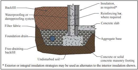
Where drainage is good, a dampproof coating of parging with a permanent bituminous coating has proven to be satisfactory. A portland cement and sand mix (1:3.5 by volume), or Type M or S mortar may be used for the parge coat. The parge coat should be beveled at the top to form a wash, and thickened at the bottom to form a cove between the wall base and top of footing, as shown in Figure 1.

To further increase water penetration resistance, a bituminous coating is applied over the parging. Coal tar or asphalt based bitumens are available in solvent for hot application, or in emulsions for application at ambient temperatures. These coatings can be sprayed, brushed, or trowelled onto the finish coat of parging.

Bentonite Panel Systems

Bentonite is a mineral that swells to many times its original size when wet. Waterproofing panels incorporate dry bentonite encased in kraft paper or fabric. After installation, the bentonite swells up the first time it is exposed to water, expanding between the foundation wall and the backfill, and forming an impervious barrier. The swelling seals small cracks in the foundation wall or punctures in the panels themselves.

To prevent premature hydration bentonite panels must be protected from moisture until they are properly installed and the foundation wall has been backfilled.

Other Systems

There are several systems for which Acceptance Criteria, developed by the ICC Evaluation Service, exist. Cold, liquid-applied, below-grade exterior dampproofing and waterproofing materials should demonstrate compliance with ICC ES AC29 (ref. 5). For rigid, polyethylene, below-grade dampproofing and waterproofing materials, compliance should be shown to ICC-ES AC114 (ref. 6).

Some systems fulfill the requirements of both waterproofing/dampproofing and wall insulation. These systems, however, may not be specified directly in the building code or have an Acceptance Criteria. In these cases, materials should be evaluated both for general waterproofing (or dampproofing) characteristics (such as resistance to hydrostatic pressure, etc.) as well as for criteria specific to the material or system. The Acceptance Criteria listed above can be used as a baseline for a material, although not all requirements may apply to all materials. An engineering evaluation of the product testing results can demonstrate acceptable performance for use as dampproofing or waterproofing.

DRAINAGE

Draining water away from basement walls significantly reduces the pressure the basement wall must resist. This reduces both the potential for cracking and the possibility of water penetration into the basement if there is a failure in the waterproof or dampproof system.

Perforated pipe or drain tiles laid with open joints have proven to be effective at collecting and transporting water away from foundation walls. The invert of drain pipes should be below the top of the floor slab elevation, as shown in Figure 1. The backfill drain should be connected to solid piping to carry the water to natural drainage, a storm sewer, or a sump. For adequate drainage, drains should slope at least in. in 10 ft (10 mm in 3 m).

Drain tile and perforated pipes are typically laid in crushed stone to facilitate drainage. At least 2 in. (51 mm) of washed gravel or free-draining backfill (containing not more than 10% material finer than a No. 4 sieve) should be placed beneath perforated pipes. Drain tiles laid with open joints are more effective when laid on the undisturbed soil where the water begins to accumulate. At least 6 to 12 in. (152 to 305 mm) of the same stone should cover the drain and should extend 12 in. (305 mm) or more beyond the edge of the footing. To prevent migration of fine soils into the drains, filter fabrics are often placed over the gravel.

Drainage pipes may also be placed beneath the slab and connected to a sump. In some cases, pipes are cast in or placed on top of concrete footings at 6 to 8 ft (1.8 to 2.4 m) o.c. to help drain water from the exterior side of the foundation wall.

The backfill material itself also significantly affects water drainage around the wall. The backfill material should be well-draining soil free of large stones, construction debris, organic materials, and frozen earth. Saturated soils, especially saturated clays, should generally not be used for backfill, since wet materials significantly increase the hydrostatic pressure on foundation walls. The top 4 to 8 in. (102 to 203 mm) of backfill should be low permeability soil so rain water is absorbed into the backfill slowly.

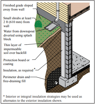
The finished grade should be sloped away from the foundation at least 6 in. within 10 ft (152 mm in 3 m) from the building, as shown in Figure 2. If the ground naturally slopes toward the building, a shallow trench or swale can be installed to direct water runoff away from the building.

Finally, gutters and downspouts should be installed to minimize water accumulation near the foundation. Water exiting downspouts should be directed away from foundation walls using plastic drainage tubing or splash blocks. Roof overhangs, balconies, and porches also shield the soil from direct exposure to rainfall.

CONSTRUCTION

Methods of construction can also impact the watertightness of foundation walls. Properly tooled mortar joints help prevent cracks from forming, and contribute to the watertightness of the finished work. Concave-shaped mortar joints are most effective for resisting water entry. Tooling the mortar compresses the surface to make it more watertight, and also reduces leakage by filling small holes and other imperfections. On the exterior face of the wall, mortar joints may be struck flush if parging will be applied.

The drainage and waterproof or dampproof system should be inspected prior to backfilling to ensure they are properly placed. Any questionable workmanship or materials should be repaired at this point, because repair is difficult and expensive after backfilling.

Backfilling methods are important, since improper backfilling can damage foundation walls or the dampproof or waterproof system. Foundation walls should either be properly braced or should have the first floor in place prior to backfilling so the wall is supported against the soil load.

Final grade should be 6 to 12 in. (152 to 305 mm) below the top of the waterproof or dampproof membrane, and should slope away from the foundation wall. In no case should the backfill be placed higher than the design grade line.

These topics are covered in more detail in ref. 7.

LANDSCAPING

Landscaping directly adjacent to the building impacts the amount of water absorbed by the foundation backfill. Particular care should be taken when automatic sprinklers are installed adjacent to foundation walls. Whenever possible, large-rooting shrubs and trees should be placed 10 to 15 ft (3 to 4.6 m) away from foundation walls. Smaller shrubs should be kept at least 2 to 3 ft (0.6 to 0.9 m) from walls. Ground covers help prevent erosion and can extend to the foundation. These elements are illustrated in Figure 2.

Asphalt and concrete parking lots, sidewalks, building aprons, stoops and driveways prevent direct absorption of water into soil adjacent to the foundation, and should be installed to slope away from the building.

REFERENCES

  1. International Building Code. International Codes Council, 2012.
  2. International Residential Code for One- and Two-Family Dwellings. International Code Council, 2012.
  3. Standard Specification for Packaged, Dry, Combined Materials for Surface Bonding Mortar, ASTM C887-05(2010) . ASTM International, Inc., 2010.
  4. Basement Manual—Design & Construction Using Concrete Masonry, CMU-MAN-002-01, Concrete Masonry & Hardscapes Association, 2001.
  5. Acceptance Criteria for Cold, Liquid-Applied, Below-Grade, Exterior Damproofing and Waterproofing Materials, ICC ES AC29. International Code Council, 2011.
  6. Acceptance Criteria for Rigid, Polyethylene, Below-Grade, Damproofing and Wall Waterproofing Material, ICC-ES AC114. International Code Council, 2011.
  7. Concrete Masonry Basement Wall Construction, TEK 03-11, Concrete Masonry & Hardscapes Association, 2001.


Design for Dry Single-Wythe Concrete Masonry Walls

INTRODUCTION

Single-wythe concrete masonry walls are cost competitive because they provide structural form as well as an attractive and durable architectural facade. However, because they do not have a continuous drainage cavity (as do cavity and veneered walls), they require special attention to moisture penetration.

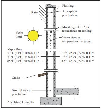
The major objective in designing dry concrete masonry walls is to keep water from entering or penetrating the wall. In addition to precipitation, moisture can find its way into masonry walls from a number of different sources (see Figure 1). Dry concrete masonry walls are obtained when the design and construction addresses the movement of water into, through, and out of the wall. This includes detailing and protecting building elements including parapets, roofs, all wall penetrations (utility and fire protective openings, fenestration, doors, etc.), movement joints, sills and other features to resist water penetration at these locations. Annotated Design and Construction Details for Concrete Masonry (ref. 1) contains comprehensive details for reinforced and unreinforced concrete masonry walls. Further, condensation and air leakage must be controlled. See the Condensation Control section on page 7.

The primary components of moisture mitigation in concrete masonry walls are flashing and counter flashing, weeps, vents, water repellent admixtures, sealants (including movement joints), post-applied surface treatments, vapor retarders and appropriate crack control measures. For successful mitigation, all of these components should be considered to be used redundantly, however not all will be applicable to all wall systems. For example, flashing and weeps are not necessary in solidly grouted construction, and may not be appropriate in areas of high wind or seismic loading where compromise of masonry shear resistance may occur (see the Wall Drainage section on page 3 for more information). The determination on structural effect must be made by the structural engineer. As another example, the use of integral water repellents for surfaces to receive a stucco finish may not be appropriate. Successful design for moisture mitigation considers each of these components, and provides for redundancy of protection, also known as a “belt and suspenders” approach.

This TEK provides a brief overview of the issues to consider when designing single wythe walls for water penetration resistance. The information presented is not meant to be comprehensive. Where appropriate, references to more detailed sources are provided.

SOURCES OF WATER IN WALLS

Driving Rain

Although concrete masonry units and mortar generally do not allow water to pass through quickly, rain can pass through if driven by a significant force. Cracks caused by building movements, or gaps between masonry and adjoining building elements are common points of water entry. If rain enters wall other than by way of the roof or at element interfaces (such as penetrations and window openings), it often can be traced to the masonry unit-mortar interface.

Capillary Action

Untreated masonry materials (without a compatible integral water repellent and/or post-applied surface treatment) typically take on water through absorption, adsorption and/or capillary forces. The amount of water depends on the characteristics of the masonry and mortar. Integral water repellents greatly reduce the absorption and adsorption characteristics of the units and mortar, but may not be able to prevent all moisture migration if there is a significant head pressure of approximately 2 in. water (51 mm) or more. Post-applied surface treatments reduce moisture penetration of masonry at the treated surface as well, but have little effect on the interior of the units.

Water Vapor

Water as vapor moves through a wall either via air leakage or by diffusion (from higher to lower: relative humidity, pressure and/or temperature). As air cools, it becomes more saturated, and when it reaches the dew point temperature the water vapor will condense into liquid form. See the Condensation Control section on page 7 for more information.

Ground Water

Protecting below-grade walls from water entry involves installing a barrier to water and water vapor. Below grade moisture tends to migrate from the damp soil to the drier area inside the basement. An impervious barrier on the exterior wall surface can prevent moisture entry. The barrier is part of a comprehensive system to prevent water penetration, which includes proper wall construction and the installation of drains, gutters, and proper grading (location of finished grade as well as grade sloping away from the building). Landscaping can also contribute to water ponding adjacent to the foundation wall and/or to insufficient drainage. IBC Section 1805 contains requirements for dampproofing and water proofing foundations. More detailed information for concrete masonry foundation walls can be found in Preventing Water Penetration in Below Grade CM Walls, TEK 19-03B (ref. 2).

DESIGN CONSIDERATIONS

When designing for moisture mitigation in walls, three levels of defense should be considered: surface protection (properly constructed mortar joints, surface water repellents, surface coatings), internal protection (integral water repellents), and drainage/drying (flashing, weeps, vents). The most successful designs often provide redundancy among these three levels. This redundant design approach helps ensure that the wall remains free of moisture problems even if one of the defense mechanisms is breached. Flashing and weeps, for example, provide a backup in case surface coatings are not reapplied as needed or leaks develop around windows or other openings. The following sections discuss the individual mechanisms in more detail.

Physical Characteristics of the Units

Open-textured concrete masonry units possessing large voids tend to be more permeable than closed-textured units. The texture can be affected by aggregate gradation, water content of the concrete mix, amount of cement in the mix, other materials in the mix such as admixtures, and the degree of compaction achieved during molding. These factors can also affect capillary action and vapor diffusion characteristics. Units should be aged at least 21 days if possible before installation to reduce the chance of shrinkage cracks at the mortar-unit interface.

Smooth-faced units facilitate mortar joint tooling, so will generally result in a more water resistant wall, as opposed to fluted units which are more difficult to tool and therefore the most susceptible to leakage. Horizontal effects such as corbels and ledges that may hold water are more prone to water penetration.

Integral Water Repellents

The use of integral water repellents in the manufacture of concrete masonry units can greatly reduce the wall’s absorption characteristics. When using units with an integral water repellent, the same manufacturer’s water repellent for mortar must be incorporated in the field for compatibility and similar reduced capillary action characteristics.

Integral water repellents make masonry materials hydrophobic, significantly decreasing their water absorption and wicking characteristics. While these admixtures can limit the amount of water that can pass through units and mortar, they have little impact on moisture entering through cracks and voids in the wall. In addition, when using an integral water repellent, any water that does penetrate can not exit as easily. Therefore, even with the incorporation of integral water repellents, flashing and weeps, as well as proper detailing of control joints and quality workmanship are still essential. See Water Repellents for Concrete Masonry Walls, TEK 19-01 (ref. 3), and Characteristics of CMU with Integral Water Repellent, TEK 19-07 (ref. 4), for more complete information on integral water repellents for concrete masonry walls.

Post-Applied Surface Treatments

For integrally colored architectural masonry, a clear surface treatment should be post-applied whether or not integral water repellent admixtures are used. Most post-applied coatings and surface treatments are compatible with integral water repellents although this should be verified with the product manufacturers before applying. When using standard units for single-wythe walls, application of a clear treatment, portland cement plaster (stucco), paint, or opaque elastomeric coating improves the water resistance of the wall. Coatings containing elastomerics have the advantage of being able to bridge small gaps and TEK 19-02B 3 CONCRETE MASONRY & HARDSCAPES ASSOCIATION masonryandhardscapes.org cracks. See Water Repellents for Concrete Masonry Walls, TEK 19-01 (ref. 3) for more detailed information.

Wall Drainage

In areas with high seismic loads, masonry walls tend to be heavily reinforced and it is often more economical to fully grout the masonry. In fully grouted masonry, flashing is not necessary. In these cases, the wall is designed as a barrier wall, rather than as a drainage wall.

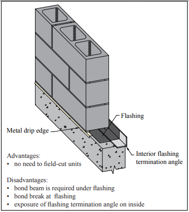
When flashing is used, the importance of proper detailing cannot be over-emphasized. Traditionally, through-wall flashing has been used to direct water away from the inside wall face and toward weep holes for drainage. Figure 2 shows one example of flashing that spans completely across the width of the wall. In this example, the termination angle prevents any water that collects on the flashing from penetrating to the interior, and the weeps and drip edge drain water to the exterior.

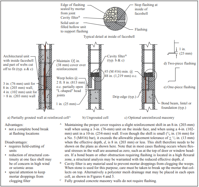
Where it is necessary to retain some shear and flexural resistance capabilities, there are several options. One is to terminate the flashing within the inside face shell of the wall, as shown in Figure 3. In reinforced walls, some shear is provided through doweling action of the reinforcement, and by design the reinforcement takes all tension (refs. 5, 6). Proper grouting effectively seals around where the vertical reinforcement penetrates the flashing. The absence of reinforcement to provide doweling in plain masonry may be more of a concern, but loads tend to be relatively low in these applications. If structural adequacy is in doubt, a short reinforcing bar through the flashing with cells grouted directly above and below can be provided as shown in Figure 3c.

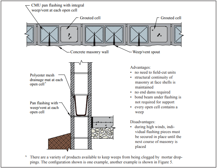
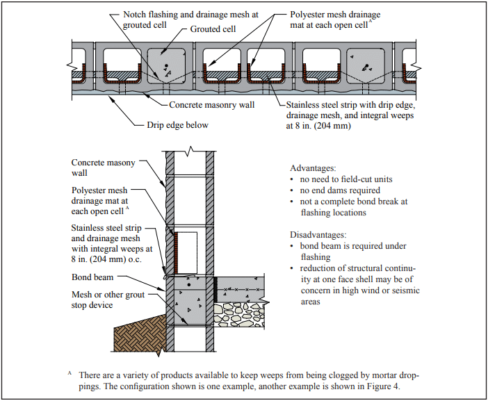
A better option to maintain shear at the level of the flashing is to use a product that maintains some bond in both face shells, such as that shown in Figure 4.

Ensuring that a buildup of mortar droppings does not clog the cells or weep holes is critical. Traditionally, a cavity filter consisting of washed pea stone or filter paper immediately above the flashing was provided to facilitate drainage, as shown in Figure 3. This should be accompanied by a means of intercepting or dispersing mortar droppings, as an accumulation can be sufficient to completely fill and block a cell at the bottom. As an alternative, mortar interception or isolation devices that provide pathways for the water to migrate through the layer of mortar droppings, or filling the cells with loose fill insulation a few courses at a time as the wall is laid up, can disperse the droppings enough to prevent clogging. Examples of polyester mesh drainage mats are shown in Figures 4 and 5. Another alternative is to leave out facing block at regular intervals just above the flashing until the wall is built to serve as cleanouts. The units left out can be mortared in later. See Flashing Strategies for Concrete Masonry Walls, TEK 19-04A and Flashing Details for Concrete Masonry Walls, TEK 19-05A, (refs. 7, 8) for an in-depth discussion and additional details regarding flashing.  

In addition to conventional flashing systems, proprietary flashing systems are available that direct the water away from the inside face of the wall to weep holes without compromising the bond at mortar joints in the face shells. See Figure 4 for one example. These are not intended to be comprehensive, but rather to provide examples of some types of available systems. Specialty units that facilitate drainage are also available from some manufacturers.

Solid grouted single-wythe walls do not require flashing because they are not as susceptible to moisture penetration, since voids and cavities where moisture can collect are absent. However, fully cured units and adequate crack control measures are especially important to minimize cracks. In some regions of the country, the bottom of the wall is recessed about 1 in. (25 mm) below the floor level to ensure drainage to the exterior.

Crack Control

Because cracks provide an entry point for rainwater and moist air, crack control provisions are very important in producing dry walls. There are various sources of potential wall cracking. A detailed list, as well as an overview of crack control strategies, can be found in Crack Control Strategies for Concrete Masonry Construction, CMU-TEC-009-23 (ref. 9).

Control joints and/or horizontal reinforcement should be located and detailed on the plans to alleviate cracking due to thermal and shrinkage movements of the building. Specifying a quality sealant for the control joints and proper installation is a must to maintain the weather-tightness of the joint. Joint Sealants for Concrete Masonry Walls, TEK 19-06A (ref. 10) contains more comprehensive information on this topic. See Crack Control Strategies for Concrete Masonry Construction, CMU-TEC-009-23 (ref. 11) for detailed information on control joint placement and construction.

Mortar and Mortar Joints

The type of mortar and type of mortar joint can also impact a wall’s watertightness. A good rule of thumb is to select the lowest strength mortar required for structural and durability considerations. Lower strength mortars exhibit better workability and can yield a better weather-resistant seal at the mortar/unit interface. See Mortars for Concrete Masonry, TEK 09-01A (ref. 12), for a more complete discussion.

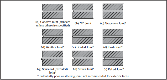
Unless otherwise specified, mortar joints should be tooled to a concave profile when the mortar is thumbprint hard (refs. 5, 13), as shown in Figure 6. For walls exposed to weather, concave joints improve water penetration resistance by directing water away from the wall surface. In addition, because of the shape of the tool, the mortar is compacted against the concrete masonry unit to seal the joint. V-shaped joints result in sharper shadow lines than concave joints. Raked, flush, struck, beaded, grapevine, squeezed or extruded joints are not recommended in exposed exterior walls as they do not compact the mortar and/or they create ledges that intercept water running down the face of the wall.

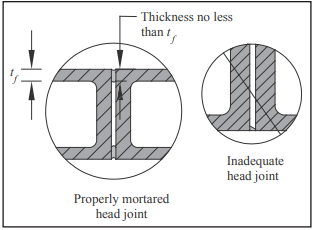
Head and bed joints should be the full thickness of the face shells for optimum water resistance. Head joints are particularly vulnerable to inadequate thickness (see Figure 7).

Condensation Control

Condensation is a potential moisture source in building assemblies. Because condensation potential varies with environmental conditions, seasonal climate changes, the construction assembly, building type and building usage, condensation control strategies vary as well. For a full discussion, see Condensation Control in Concrete Masonry Walls, TEK 06-17B, and Control of Air Leakage in Concrete Masonry Walls, TEK 06-14A (refs. 14, 15).

Note that the location and vapor permeability of insulation can influence the condensation potential of a wall. The following references provide more detailed information. Insulating Concrete Masonry Walls, TEK 06-11A (ref. 16), discusses various insulation strategies and the advantages and disadvantages of each. R-Values and U-Values for Single Wythe Concrete Masonry Walls, TEK 06-02C, and Thermal Catalog of Concrete Masonry Assemblies (refs. 17, 18) provide calculated thermal values of various walls and insulation types. Details for Half-High Concrete Masonry Units, TEK 05-15 (ref. 19), contains comprehensive details of various single wythe walls.

Cleaning

Concrete masonry cleaning methods can generally be divided into four categories: hand cleaning, water cleaning, abrasive cleaning and chemical cleaning. In general, the least aggressive method that will adequately clean the wall should be used, as overzealous cleaning can damage the water repellent characteristics of the wall. Keeping the masonry wall clean as the construction progresses using a brush and water minimizes cleaning efforts after the mortar has hardened. See Cleaning Concrete Masonry, TEK 08-04A (ref. 20) for more detailed information.

SPECIFICATIONS

Well-worded specifications are essential to ensure the design details are properly constructed. Items to address in the contract documents in addition to those previously mentioned include:

  1. All work to be in accordance with the International Building Code and Specification for Masonry Structures (refs. 5, 13).
  2. Require a qualified mason by documentation of experience with similar type projects.
  3. Require sample panels to assure an understanding of the level of workmanship expected and to be used as a standard of reference until the project is completed.
  4. Proper storage of all masonry materials (including sand) at the job site to protect from contaminants such as dirt, rain and snow.
  5. The tops of unfinished walls shall be covered at the end of each work day. The cover should extend 2 ft (610 mm) down each side of the masonry and be held securely in place.

REFERENCES

  1. Annotated Design and Construction Details for Concrete Masonry, TR 90. National Concrete Masonry Association, 2002.
  2. Preventing Water Penetration in Below-Grade CM Walls, TEK 19-03B, Concrete Masonry & Hardscapes Association, 2012.
  3. Water Repellents for Concrete Masonry Walls, TEK 19-01, Concrete Masonry & Hardscapes Association, 2006.
  4. Characteristics of CMU with Integral Water Repellent, TEK 19-07, Concrete Masonry & Hardscapes Association, 2008.
  5. International Building Code. International Code Council, 2012.
  6. Building Code Requirements for Masonry Structures, TMS 402-11/ACI 530-11/ASCE 5-11, reported by the Masonry Standards Joint Committee, 2011.
  7. Flashing Strategies for Concrete Masonry Walls, TEK 1904A, Concrete Masonry & Hardscapes Association, 2008.
  8. Flashing Details for Concrete Masonry Walls, TEK 19-05A, Concrete Masonry & Hardscapes Association, 2008.
  9. Crack Control Strategies for Concrete Masonry Construction, CMU-TEC-009-23, Concrete Masonry & Hardscapes Association, 2023.
  10. Joint Sealants for Concrete Masonry Walls, TEK 19-06A, Concrete Masonry & Hardscapes Association, 2014.
  11. Crack Control Strategies for Concrete Masonry Construction, CMU-TEC-009-23, Concrete Masonry & Hardscapes Association, 2023.
  12. Mortars for Concrete Masonry, TEK 09-01A, Concrete Masonry & Hardscapes Association, 2004.
  13. Specification for Masonry Structures, TMS 602-11/ACI 530.1-11/ASCE 6-11, reported by the Masonry Standards Joint Committee, 2011.
  14. Condensation Control in Concrete Masonry Walls, TEK 06-17B, Concrete Masonry & Hardscapes Association, 2011.
  15. Control of Air Leakage in Concrete Masonry Walls, TEK 06-14A, Concrete Masonry & Hardscapes Association, 2011.
  16. Insulating Concrete Masonry Walls, TEK 06-11A, Concrete Masonry & Hardscapes Association, 2010.
  17. R-Values and U-Values for Single Wythe Concrete Masonry Walls, TEK 06-2C, Concrete Masonry & Hardscapes Association, 2012.
  18. Thermal Catalog of Concrete Masonry Assemblies, CMU-MAN-004-12, Concrete Masonry & Hardscapes Association, 2012.
  19. Details for Half-High Concrete Masonry Units, TEK 05-15, Concrete Masonry & Hardscapes Association, 2010.
  20. Cleaning Concrete Masonry, TEK 08-04A, Concrete Masonry & Hardscapes Association, 2005.


Compressive Strength Testing Variables for Concrete Masonry Units

INTRODUCTION

Anyone engaged in testing concrete masonry units or prisms, or interpreting test results, should be familiar with testing variables and their significance. Variables both prior to and during testing may significantly influence test results. Tests conducted to establish design criteria will affect the wall sections selected, and often will have a direct effect on the economics of the building.

Except for certain architectural facing units such as split block and slump block, concrete masonry units are manufactured to relatively precise dimensional tolerances. Because of this, it might be assumed that the units are not sensitive to variations during testing, although this is not necessarily true. Changes in concrete masonry unit moisture content can cause changes in the physical characteristics. Increases in moisture content of concrete masonry units at the time of testing reduces compressive strength. Volume change can also be influenced by the presence of moisture. Upon drying, concrete masonry units undergo shrinkage.

These conditions, i.e., strength gain and volume change, may occur simultaneously during the test period. Consequently, the effect of variables on the strength properties of the unit should be known. Testing, per se, thus becomes a conscientious effort to exclude known variables, adhere to prescribed testing methods, and present true test results.

This TEK discusses variables which may be encountered during testing of concrete masonry units. The person performing tests, and the person interpreting results, should assure themselves that all necessary precautions have been taken to render variables insignificant, or preferably nonexistent.

APPLICABLE STANDARDS

Compressive strength testing procedures for concrete masonry units and other related products are covered by ASTM C 140, Standard Methods of Sampling and Testing Concrete Masonry Units. By reference to other standards, items such as the requirements for the testing machine are covered. The completeness of these test methods disallows much variation. Strict adherence to the laboratory procedures outlined in this standard test method is critical to obtaining accurate results.

Both the tester and the interpreter should have a working knowledge of the procedures in ASTM C 140, the effects of test variables on results, and the requirements of the product specification which establishes minimum criteria for the unit being tested.

VARIABLES

Variables which may influence the reported test value include the test specimen and its preparation, the physical testing machine, the tester’s use of the machine, the placement of the specimen within the machine, plate thickness for compression testing, and the testing procedure used.

Variables in the concrete masonry unit that can influence the test results include the moisture content of the concrete masonry unit at the time of test and the geometry (shape) of the concrete masonry unit.

Moisture Content of the Concrete Masonry Unit at Testing

The moisture content of the concrete masonry unit at the time of test may have a significant effect on the reported test value. Testing of concrete masonry at various moisture contents, Figure 1, has demonstrated that moisture content may be responsible for a higher or lower reported test value. Oven-dry units possess higher tested compressive strengths than their normal (air-dry) moisture content counterpart. Conversely, concrete masonry units tested wetter than their normal counterpart yield lower compressive strengths. The approximate twenty percent increase or decrease is significant. This finding strongly suggests that sampled units destined for compressive strength testing should be maintained in their “as-received” or “as-desired” moisture condition. To help ensure this, ASTM C 140 requires that units be stored until tested in air at a temperature of 75 + 15 °F (24 + 8 °C) and a relative humidity of less than 80%, and not be subject to oven drying.

The cause for this strength increase-decrease is attributed to secondary hydraulic pressure which develops as the unit and water within the unit are subjected to external pressure. The loads are additive, so higher moisture contents yield larger strength reductions. Conversely, an oven-dry specimen possesses internal tensile strains, which must be overcome by compressive forces before the strains become compressive.

Reducing the moisture content of a specimen is even more significant when testing involves tensile strength properties, bond strength, or flexural strength. The strength reduction is greatest at the early period after specimen relocation to a drier environment. Again, maintaining the test specimen in the steady or equilibrated state is the proper way to conduct testing.

The moisture condition of concrete masonry at the time of testing may alter the true load carrying capacity of the unit.

Geometry (Shape) of the Test Specimen

Any material being tested, using test sections with various heights while maintaining a constant cross section, will yield higher compressive strengths as the ratio of the height to thickness of the specimen decreases. A tall specimen possesses a lower load carrying capacity than a short or shorter specimen. Test specimens subjected to compressive loads fail through a combination of compression and tension. Tall specimens are more sensitive to the influence of tensile stress, while short specimens fail in bearing.

Although the general trend toward strength reduction is known, the height to thickness ratio (h/t) influence normally used to identify specimen shape effects varies with aggregate type, concrete masonry strength, moisture content, etc. A concrete brick from the same mixture used to produce a concrete block may have a higher apparent compressive strength than its block counterpart. The shape effect contributes as does the degree of consolidation during manufacturing and the effectiveness of unit curing.

ASTM C 140 includes h/t correction factors for segmental retaining wall unit specimens with aspect ratios less than two. When coupons are used as compression specimens, they are cut at an h/t of 2, so correction factors are not needed. Figure 2 illustrates the effect of aspect ratio on apparent compressive strength of solid specimens. Hollow concrete masonry units are less affected by variations in h/t. For example, research has shown little change in apparent compressive strength when the unit height is reduced by one-third or less.

Tester Influenced Variables

A laboratory technician may significantly alter the failure compression test load, either consciously or unconsciously. Technician procedural influences include: (1) selection and maintenance of the physical testing machine and its accessories, such as bearing blocks and testing plates; (2) selection of capping material and application of a proper cap; (3) the positioning of the specimen for test; and (4) the rate of loading. Singly or collectively, these factors will influence the failure load. It is of interest to note that these variables, with the exception of a rapid rate of loading, will cause a lower reported failure load.

Testing machines should conform to the requirements of ASTM E 4, Practices for Force Verification of Testing Machines. The verification of the testing machine occurs under different loading conditions than those that prevail during actual test. The accessories such as bearing block or plates, and thin plates which deflect during loading, cause the same strength reduction discussed below for imperfect caps. Oil on the plates of the machine will also reduce the failure load result.

Capping materials vary in composition and, consequently, so does their modulus of elasticity. Approved (ASTM C 1552 Practice for Capping Concrete Masonry Units and Masonry Prisms for Compression Testing) capping compounds include mixtures of 40 to 60% sulfur and ground fire clay and other suitable material passing a No. 100 (150 µm) sieve or high strength gypsum cement. The use of alternate materials should not be permitted. Fiber board or other similar materials will compress more readily than their approved counterpart. Compressing the fiber board causes it to spread laterally, inducing tensile stresses into the test specimen and resulting in a lower apparent compressive strength. The resulting strength may still allow product certification if the strength value surpasses the minimum specified value. Results can vary from twenty to forty percent below the properly capped counterpart value. Because the compression results are conservative, many block producers use this less-labor intensive method as a means of assuring their compliance with specified minimum compressive strengths.

Capping materials that are not properly applied to the unit may be responsible for nonuniform stressing of the specimen during loading. A fifteen percent loss in strength has been measured for units improperly capped.

ASTM C 1552 requires the capping plate to be plane and rigid enough not to deflect during capping. Deflection of the capping plate results in a crown on the testing surface of the units, leading to nonuniform load distribution and lower apparent compressive strengths. One-half inch (13 mm) thick glass plates placed on top of 1 in. (25 mm) thick steel plates are recommended. The glass plates provide a smooth scratch-resistant replaceable wear surface while the steel plates provide needed stiffness to the capping station.

Similarly, the steel bearing plates on the compression testing machine must be rigid enough not to deflect during testing. Small deflections, unnoticeable to the naked eye, will negatively impact test results. ASTM C 140 requires that the steel bearing plates have a thickness at least equal to the distance from the edge of the spherical bearing block to the most distant corner of the specimen. This thickness must be achieved by using a single plate having a width and length at least ¼ in. (6.4 mm) greater than the length and width of the specimen being tested. Stacking several plates to reach the required plate thickness will be less rigid than a single plate of the required thickness. It is also required that the bearing faces of the plates have a Rockwell hardness of at least HRC 60 (BHN 620).

Oil on the testing plates or platens of the testing machine, or the capped surfaces of the test specimen, will also reduce the failure load. The oil lubricates the interface between specimen and machine. The result is that the test specimen expands at the interface; tensile failure occurs sooner and at a lower load.

Positioning of the test specimen within the machine can have a significant effect on the failure load. For units that are essentially symmetrical the positioning is important, but to a lesser degree than when unsymmetrical units are being tested. The applied load of the testing machine should pass through the centroid of the test specimen. Units tested with applied load other than at the centroid can provide an array of reported values, Figure 3. Loads not applied through the center of mass of the unit results in lower tested strengths and increased variability in results.

For masonry units that are symmetrical about an axis, the location of that axis can be determined geometrically by dividing the dimension perpendicular to that axis (but in the same plane) by two. For masonry units that are nonsymmetrical about an axis, the location of that axis can be determined by balancing the masonry unit on a knife edge or a metal rod placed parallel to that axis. If a metal rod is used, the rod must be straight, cylindrical (able to roll freely on a flat surface), have a diameter of not less than ¼ in. (6.4 mm) and not more than ¾ in. (19.1 mm), and it must be longer than the specimen. Once determined, the centroidal axis is to be marked on the end of the unit.

Speed of Testing

The compression machine operator can also influence the test value by altering the rate of loading. Generally, rapid loading of a specimen will yield a higher apparent failure load than the less rapid or normal rate of loading. Loading should occur at some convenient rate to approximately one-half of the expected ultimate load. Thereafter the rate of loading should be adjusted such that failure occurs within the period from 1 to 2 minutes.

SUMMARY

The primary objective of testing concrete masonry units is to establish product quality for acceptance and to aid the design engineer toward selection of materials and their combination in the most economical wall section or structure. Unchecked variables during product testing invariably increase the cost of the wall. The effects of these variables will be lessened by conforming with the requirements high-lighted in the checklist, Table 1.

Unless controlled, testing variables will influence tested strength properties of concrete masonry. Variables which will result in higher compressive strength include the geometry (shape) of the specimen, rapid rate of load application, and low moisture content at the time of testing. Other testing variables such as improper application of the capping material, high moisture content at time of test, use of “thin” bearing plates, and improper positioning in the compression machine, will reduce the failure load value. Both extremes should be avoided.

Accurate and correct tested values are critical to masonry construction and design. Conservative results increase the factors of safety for design, but may result in uneconomical construction. The cost required to resolve compounding errors in judgement resulting from inaccurate testing is much greater than the cost required to use and maintain the right equipment and to properly train testing technicians to understand the effects of those variables discussed here.

Condensation Control in Concrete Masonry Walls

INTRODUCTION

Condensation is one type of moisture to which buildings can potentially be exposed. In addition to above grade precipitates of rain, snow and ice as well as high humidity, several forms of below-grade ground-sourced moisture can also affect building envelopes. Concrete masonry walls are less affected by the problems associated with moisture infiltration and condensate than other building materials (i.e. corrosion, rotting, mold, delamination, blistering and volumetric changes). However, prolonged moisture accumulation can lead to reduced effectiveness of some types of thermal insulation, temporary frost formation and/or efflorescence. Fortunately, these problems can largely be avoided with proper wall design and construction.

Above- and below-grade condensation control strategies include: limiting air leakage and water vapor diffusion, using adequate amounts of thermal insulation, minimizing cold spots, utilizing free draining flashing and weeps, and allowing for drying. Because the condensation potential in a particular assembly can vary with the construction assembly, building type, building usage as well as environmental conditions and seasonal climate changes, however, these strategies may vary from project to project.

CONDENSATION

Warmer air can hold more water in vapor form than can cold air. When warm moist air comes into contact with a cold surface, the air cools and can no longer hold all of its water vapor—the excess moisture condenses.

Local cold spots in a wall can cause small areas of condensation. Cold spots are usually caused either by thermal bridging or by air leakage. Both can be avoided with appropriate design strategies. See TEKs 06-13B Thermal Bridges in Wall Construction and 06-14A Control of Air Leakage in Concrete Masonry Walls (refs. 1, 2) for more detailed information.

Restricting Water Vapor Flow

Water vapor can move through building envelope assemblies by diffusion and via air leakage, so both mechanisms must be considered. The amount of water vapor that travels via air movement can be several orders of magnitude greater than that due to diffusion. Therefore, limiting air leakage is an important water vapor control strategy. For detailed information on reducing air leakage, see TEK 06-14A. When an air barrier material is required, the vapor permeability of the material must be evaluated relative to the material’s location within the wall to help ensure that the air barrier material is not contributing to moisture problems due to vapor diffusion.

Proper design and construction to reduce liquid water entry into wall assemblies will also help reduce condensation potential by reducing moisture surface area and the related water vapor diffusion. The use of moisture tolerant building materials, such as concrete masonry, also reduces the potential damage from condensation and other moisture sources.

A balanced mechanical system backed by an appropriate maintenance program is assumed for optimum efficiency. Supplying draft-controlled make-up air for all exhaust fans reduces air infiltration.

When required, water vapor retarders are used to restrict water vapor diffusion (versus moisture movement due to air leakage). Although the main characteristic of water vapor retarders is vapor permeance, other considerations may include mechanical strength, adhesion, elasticity, thermal stability, fire and flammability resistance, resistance to other deteriorating elements (e.g., chemicals, UV radiation), and ease of application and joint sealing.

A vapor retarder’s effectiveness depends on both its vapor permeance and location within the wall assembly. In addition, because of the large potential for moisture movement with air movement, a vapor retarder in an assembly with high air leakage will be ineffective.

Vapor retarders can limit water vapor movement by diffusion, but can also limit the ability of the assembly to dry. Both results need to be considered in the design. In some cases, using a semi-permeable vapor retarder, or not using a vapor retarder, is recommended to ensure the wall assembly can adequately dry. Other design conditions may dictate the use of a vapor retarder of very low permeance. Each design should be evaluated with the goal of balancing the need to restrict vapor diffusion and the need to allow drying.

Materials are also available that serve as both the vapor retarder and airflow retarder, and are useful when the assessment of air flow control and vapor diffusion control so dictates.

The 2009 International Residential Code (ref. 8) defines three vapor control classes as follows:

  • Class I: <0.1 perms, such as polyethylene sheet, sheet metal or aluminum facing.
  • Class II: 0.1 – 1.0 perms, such as kraft faced fiberglass batts, and some vapor control paints.
  • Class III: 1.0 – 10 perms, such as some latex or enamel paints.

CONDENSATION CONTROL

Condensation control focuses on minimizing airflow through the wall, interrupting water vapor diffusion, maintaining temperatures above the dew point for surfaces exposed to moisture, and allowing for drying.

Condensation can occur in either summer or winter. Design strategies for moisture control (including moisture vapor and humid air) under heating conditions often differ from those for cooling conditions, even though the basic principles of moisture transfer are the same.

In cold climates, moisture tends to be driven from the warm moist interior to the cold dry exterior. Condensation control under these conditions favors strategies that hold the moisture within the insulated envelope. In hot and humid climates, warm moist exterior air is driven towards the cooler drier interior. In this case, the wall should be designed to keep the moisture on the exterior of the wall. Most climates have some combination of the above conditions. In addition, moisture control in certain building types, such as hotels, motels, and cold storage facilities, will often benefit from using the recommendation for warm humid climates, regardless of the building location.

Definitions of climate zones for condensation control are based on the climate zones used in the International Energy Conservation Code (IECC) (ref. 3). The map showing these zones can be found at http://www1.eere.energy.gov/buildings/residential/ba_climate_guidance.html. Climate zones for the United States are: Sub-arctic, very cold, cold, mixed-humid, hot-humid, hot-dry, mixed-dry and marine. These zones are illustrated in Figure 1 for the continental U.S. along with their corresponding IECC climate zones.

Recommendations by Climate Zone

The following sections describe U. S. Department of Energy (DOE) general recommendations (ref. 5) for controlling water vapor movement and allowing drying in new residential construction, based on the climate zones shown in Figure 1.

All recommendations should be considered as part of a comprehensive strategy that addresses items including moisture management (including liquid and vapor, as well as drying potential), energy efficiency, air infiltration and durability.

All Climates

Some recommendations are consistent across all climates:

  1. An air space, such as the properly drained open cores of a single wythe masonry wall or the cavity in a masonry cavity wall, is recommended in all climate zones. The air space provides a drainage plane and allows for better drying. Single wythe masonry walls with completely filled grout spaces will take longer to dry than concrete masonry walls with unfilled cores or a cavity. However, these walls have a large hygroscopic moisture capacity and tend not to be damaged by the longer drying period.
  2. Impermeable interior coverings, such as vinyl wallpaper, are not recommended for exterior walls, because their non-breathable nature tends to trap moisture, inhibit drying and therefore can contribute to mold and mildew within such finishes.
  3. Interior polyethylene vapor retarders are generally not recommended, because they limit the wall’s ability to dry towards the inside. In some cases, these may be mandated by building codes, particularly in wet climates.

In this case, wall assemblies should be carefully designed to accommodate building materials, local climate conditions, and interior moisture loads.

An additional consideration applies to masonry veneers under certain summer conditions. If masonry is not treated for water repellency, water can be absorbed during heavy rains. Subsequent solar heating evaporates some water, raising the water vapor pressure of air in the wall, and potentially causing condensation. This can be prevented by using surface or integral water repellents to restrict wetting of the masonry, or by applying parging or sheathing paper on the exterior side of the insulation.

Cold and Very Cold Climates

Roughly the northern half of the United States experiences a heating dominated climate. Many areas also experience hot summers, however, so both seasons should be considered when designing for condensation control.

In cold and very cold climates, air barriers and vapor retarders are installed on the interior side of the insulation in building envelope assemblies when used. This approach allows the wall assembly to dry towards the exterior, as long as vaporpermeable exterior materials are used. For exterior masonry walls, drywall painted with latex paint (Class III) provides a sufficient vapor retarder.

Hot-Dry & Mixed-Dry Climates

Design considerations for the dry climates tend to focus less on water vapor control and more on issues such as intense solar radiation, brief heavy rains, and managing fire risk. Wall interiors can be painted but not covered with plastic vapor retarders or impervious coatings, such as vinyl wallpaper.

Hot and Humid Climates

Moisture is a significant problem in these climates in terms of both high humidity and high rainfall. Controlling the infiltration of this moisture-laden air into the building envelope and keeping moisture away from cold surfaces are the goals of design and construction in this climate zone.

Ideally in these climates, batt insulation, if used, should be unfaced. However, codes may restrict the use of unfaced batts in wall construction. In addition, because of the susceptibility of batt insulation to moisture, its use is not generally recommended in masonry wall assemblies. Though there are some exceptions, generally all wall interiors and finishes which are part of an insulated masonry wall assembly may be painted or otherwise finished if desired so long as such finishes and assemblies are breathable and permeable as Code and Standards allow. Masonry buildings in Florida have successfully used a non-breathable elastomeric paint on the exterior of the wall to serve as the vapor retarder.

In hot-humid climates the interior space should be dehumidified. Properly sized air-conditioning equipment will help reduce indoor humidity—oversized units should be avoided because they either cycle on and off too frequently or are off for too long a time to effectively dehumidify.

In humid climates, moisture may condense on wall exteriors, because the wall temperature can be below the ambient dew point. Areas such as shaded reentrant building corners are more difficult to dry, since they do not have the benefit of sun and wind for evaporation. In addition, extra care is required for building components prone to thermal bridging, such as walls adjacent to slab or floor edges as well as parapet courses adjacent to roof joists and decks (see Ref. 1 for information on control of thermal bridges).

Mixed-Humid Climates

The mixed-humid climate zone has generally moderate conditions, but can experience very cold winters and hot, humid summers. In these areas, wall assemblies need to be protected from getting wet from both the interior and exterior and should also be allowed to dry to either the exterior or interior.

Perhaps the least costly option is to allow water vapor to “flow through,” by using vapor-permeable building materials on both the interior and exterior. This allows water vapor to diffuse through the assembly from interior to exterior during heating periods and from exterior to interior during cooling periods. If a vapor retarder is used, a semi-permeable (i.e., Class III) vapor retarder on just the interior side is considered adequate. Although the DOE suggests latex paint as an adequate vapor retarder in these climates (ref. 5d), the permeability of latex paints varies with the specific paint and the number and thickness of coats. Consult the manufacturer for specific permeabilities.

Installing vapor retarders on both the interior and exterior to block moisture entry from both directions is not recommended, as any moisture that enters the wall is trapped.

Marine Climates

The marine climate zone also has moderate conditions most of the time, although weather conditions similar to those found in neighboring climate zones occasionally occur. Buildings in the marine climate zone are faced with high interior and exterior moisture loads.

Similar to mixed-humid climates, building assemblies need to be protected from getting wet from both the interior and exterior and should be allowed to dry to either the exterior or the interior. The same wall recommendation apply to marine climates as to mixed humid climates, however, the high moisture loads in the marine climate zone warrant careful consideration of material vapor permeabilities, moisture loads and local climate conditions.

Vapor retarders may be required by building codes, but an option exists for engineered wall designs that do not require vapor retarders to be approved by building officials.

DETERMINING CONDENSATION POTENTIAL

Traditionally, condensation potential has been estimated using steady-state calculations of water vapor pressure and saturation pressures at various points in an assembly. If the calculated vapor pressure exceeds the saturation pressure, condensation is likely to occur if the assumed conditions occur in the field.

This dew point method is a simplified approach which can be used to estimate seasonal mean conditions (rather than daily or even weekly mean conditions) (see Figure 2). However, this method has several disadvantages. For example, wetting and drying cycles cannot be analyzed, since moisture storage within building materials is neglected, as is moisture transfer due to airflow. As a result, the analysis cannot accurately indicate potential damage due to condensation. A complete description of the dew point method is presented in the ASHRAE Handbook, Fundamentals (ref. 6).

Transient computer models which model heat, air and moisture response are an alternative to dew point analyses. They can be used to predict daily or hourly moisture conditions within assemblies. The ASHRAE Handbook, Fundamentals, contains a discussion of input and output parameters, as well as considerations for choosing a program and evaluating the results.

BASEMENTS

Moisture control in basements begins with proper protection from liquid moisture, such as from rain and wet soil. These considerations are addressed in TEK 19-03B, Preventing Water Penetration in Below-Grade Concrete Masonry Walls (ref. 7). If the wall is substantially above grade, condensation control recommendations for the appropriate climate, discussed above, should be followed. If substantially below grade, the basement walls will be dampproofed or waterproofed as required by local code, which essentially acts as an exterior vapor retarder. In this case, an additional interior vapor retarder should be avoided, as this may potentially trap moisture within the wall.

Moisture on the interior of basement walls may be caused by either condensation of interior moisture or leakage of liquid water through the wall. To determine the cause, tape a square of impermeable plastic (such as 6 mil polyethylene) on a portion of the wall experiencing the moisture issues. If there is moisture accumulating under the plastic, an exterior moisture source should be suspected. If moisture forms on top of the plastic, condensation is occurring.

REFERENCES

  1. Thermal Bridges in Wall Construction, TEK 06-13B, Concrete Masonry & Hardscapes Association, 2010.
  2. Control of Air Leakage in Concrete Masonry Walls, TEK 06-14A, Concrete Masonry & Hardscapes Association, 2011.
  3. International Energy Conservation Code. International Code Council, 2009.
  4. Guide to Determining Climate Regions by County, PNNL17211. Pacific Northwest National Laboratory and Oak Ridge National Laboratory, 2010.
  5. Building America Best Practices Series: Builders and Buyers Handbook for Improving New Home Efficiency, Comfort, and Durability. U. S. Department of Energy Building Technologies Program. Available at http://www1.eere.energy.gov/buildings/residential/ba_climate_
    guidance.html
    .
    5a. Volume 1, Hot and Humid Climates, NREL/TP-550-36960, 2004.
    5b. Volume 2, Hot-Dry and Mixed-Dry Climates, NREL/TP550-38360, 2005.
    5c. Volume 3, Cold and Very Cold Climates, NREL/TP-550-38309, 2005.
    5d. Volume 4, Mixed-Humid Climates, NREL/TP-550-38448, 2005.
    5e. Volume 5, Marine Climates, NREL/TP-550-38449, 2006.
  6. ASHRAE Handbook, Fundamentals. American Society of Heating, Refrigerating, and Air-Conditioning Engineers., Inc., 2009.
  7. Preventing Water Penetration in Below-Grade Concrete Masonry Walls, TEK 19-03B, Concrete Masonry & Hardscapes Association, 2012.
  8. International Residential Code. International Code Council, 2009.

Thermal Bridges in Wall Construction

INTRODUCTION

Thermal bridging occurs when a relatively small area of a wall, floor or roof loses much more heat than the surrounding area. Thermal bridging can occur in any type of building construction. The effects of thermal bridging may include increased heat loss, occupant discomfort, unanticipated expansion/contraction, condensation, freeze-thaw damage, and related moisture and/or mold problems for materials susceptible to moisture. The severity of the thermal bridge is determined by the extent of these effects.

Thermal bridges, and the subsequent damage, can be avoided by several strategies which are best implemented during the design stage, when changes can be easily incorporated. After construction, repairing thermal bridges can be both costly and difficult.

THERMAL BRIDGING

A thermal bridge allows heat to “short circuit” insulation. Typically, this occurs when a material of high thermal conductivity, such as steel framing or concrete, penetrates or interrupts a layer of low thermal conductivity material, such as insulation. Thermal bridges can also occur where building elements are joined, such as exposed concrete floor slabs and beams that abut or penetrate the exterior walls of a building.

Causes

Thermal bridging is most often caused by improper installation or by material choice/building design. An example of improper installation leading to thermal bridging is gaps in insulation, which allow heat to escape around the insulation and may also allow air leakage. For this reason, insulation materials should be installed without gaps at the floor, ceiling, roof, walls, framing, or between the adjacent insulation materials. Further, insulation materials should be installed so that they remain in position over time.

Although thermal bridging is primarily associated with conduction heat transfer (heat flow through solid materials), thermal bridging effects can be magnified by heat and moisture transfer due to air movement, particularly when warm, moist air enters the wall. For this reason, buildings with typically high interior humidity levels, such as swimming pools, spas, and cold storage facilities, are particularly susceptible to moisture damage. Proper installation of vapor and air retarders can greatly reduce moisture damage caused by thermal bridges. Concrete masonry construction does not necessarily require separate vapor or air retarders: check local building codes for requirements.

Minimizing moisture leakage will also alleviate thermal bridging due to air leakage for two reasons: air will flow through the same points that allow moisture entry; and water leakage can lead, in some cases, to degradation of air barriers and insulation materials.

Effects

Possible effects of thermal bridges are:

  • increased heat loss through the wall, leading to higher operating costs,
  • unanticipated expansion and/or contraction,
  • local cold or hot spots on the interior at the thermal bridge locations, leading to occupant discomfort and, in some cases, to condensation, moisture-related building damage, and health and safety issues,
  • local cold or hot spots within the wall construction, leading to moisture condensation within the wall, and possibly to damage of the building materials and/or health and safety problems, and/or
  • local warm spots on the building exterior, potentially leading to freeze-that damage, such as ice dams, unanticipated expansion or contraction, and possible health and safety issues.

Not all thermal bridges cause these severe effects. However, the severity of a particular thermal bridge should be judged by the effect of the thermal bridge on the overall energy performance of the building; the effect on occupant comfort; the impact on moisture condensation and associated aesthetic and/or structural damage; and degradation of the building materials. Appropriate corrective measures can then be applied to the design.

Requirements

ASHRAE Standard 90.1, Energy Standard for Buildings Except Low-Rise Residential Buildings (ref. 1) (included by reference in the International Energy Conservation Code (ref. 2)) addresses thermal bridging in wall, floor and roof assemblies by mandating that thermal bridging be accounted for when determining or reporting assembly R-values and U-factors. For concrete masonry walls, acceptable methods for determining R-values/U-factors that account for the thermal bridging through concrete masonry unit webs include: testing, isothermal planes calculation method (also called series-parallel calculation method), or two-dimensional calculation method. CMHApublished R-values and U-factors, such as those in TEK 06-
01C, R-Values of Multi-Wythe Concrete Masonry Walls, TEK 06-02C, R-Values and U-Factors for Single Wythe Concrete Masonry Walls, and the Thermal Catalog of Concrete Masonry Assemblies (refs. 4, 5, 6), are determined using the isothermal planes calculation method. The method is briefly described in TEK 06-01C as it applies to concrete masonry walls.

SINGLE WYTHE MASONRY WALL

In a single wythe concrete masonry wall the webs of the block and grouted cores can act as thermal bridges, particularly when the cores of the concrete masonry units are insulated. However, this heat loss is rarely severe enough to cause moisture condensation on the masonry surface, or other aesthetic or structural damage. These thermal bridges are taken into account when determining the wall’s overall R-value, as noted above. In severe climates, in certain interior environments where condensation may occur under some conditions, or when otherwise required, the thermal bridging effects can be eliminated by applying insulation on the exterior or interior of the masonry, rather than in the cores. In addition, thermal bridging through webs can be reduced by using a lighter weight masonry unit, or by using special units with reduced web size, or by using units that have fewer cross webs.

Horizontal joint reinforcement is often used to control shrinkage cracking in concrete masonry. Calculations have shown that the effect of the joint reinforcement on the overall R-value of the masonry wall is on the order of 1 – 3%, which has a negligible impact on the building’s energy use.

CONCRETE MASONRY CAVITY WALL

In masonry cavity walls, insulation is typically placed between the two wythes of masonry, as shown in Figure 1. This provides a continuous layer of insulation, which minimizes the effects of thermal bridging (note that some references term the space between furring or studs as a “cavity,” which differs from a masonry cavity wall).

Because the wall ties are isolated from the interior, the interior surface of the wall remains at a temperature close to the building’s interior temperature. The interior finish material is not likely to be damaged due to moisture condensation, and occupant comfort is not likely to be affected. As with horizontal joint reinforcement in single wythe construction, the type, size, and spacing of the ties will affect the potential impact on energy use.

MASONRY VENEER WITH STEEL STUD BACKUP

Figure 2 shows a cross section of a typical concrete masonry veneer over a steel stud backup. Steel studs act as strong thermal bridges in an insulated wall system. Almost 1,000 times more heat flows through the steel than through mineral fiber insulation of the same thickness and area. The steel stud allows heat to bypass the insulation, and greatly reduces the insulation’s effectiveness.

Just as for concrete masonry webs, the thermal bridging through steel studs must be accounted for. According to ASHRAE Standard 90.1, acceptable methods to determine the R-value of insulated steel studs are: testing, modified zone calculation method, or using the insulation/framing layer adjustment factors shown in Table 1. The effective framing/cavity R-value shown in Table 1 is the R-value of the insulated steel stud section, accounting for thermal bridging. Using these corrected R-values allows the designer to adequately account for the increased energy use due to the thermal bridging in these wall assemblies.

Table 1 shows that thermal bridging through steel studs effectively reduces the effective R-value of the insulation by 40 to 69 percent, depending on the size and spacing of the steel studs and on the R value of the insulation.

Because the steel studs are typically in contact with the interior finish, local cold spots can develop at the stud locations. In some cases, moisture condenses causing dampness along these strips. The damp areas tend to retain dirt and dust, causing darker vertical lines on the interior at the steel stud locations. If warm, moist indoor air penetrates into the wall, moisture is likely to condense on the outer flanges of the steel studs, increasing the potential for corrosion of studs and connectors and structural damage of the wall. Gypsum sheathing on the exterior of the studs can also be damaged due to moisture, particularly during freeze-thaw cycles. These impacts can be minimized by including a continuous layer of insulation over the steel stud/insulation layer.

SLAB EDGE & PERIMETER BEAM

Another common thermal bridge is shown in Figure 3. When this wall system is insulated on the interior, as shown on the left, thermal bridging occurs at the steel beam and where the concrete floor slab penetrates the interior masonry wythe.

A better alternative is to place insulation in the cavity, as shown on the right in Figure 3, rather than on the interior. This strategy effectively isolates both the slab edge and the steel beam from the exterior, substantially reducing heat flow through these areas and condensation potential, and decreasing heating loads (ref. 3).

A third alternative, not illustrated, is to install insulation on the interior of the steel beam. This solution, however, does not address the thermal loss through the slab edge. In addition, the interior insulation causes the temperature of the steel beam to be lower, and can lead to condensation unless a tight and continuous vapor retarder is provided.

MASONRY PARAPET

Because a parapet is exposed to the outside environment on both sides, it can act as a thermal fin, wicking heat up through the wall. Figure 4 shows two alternative insulation strategies for a masonry parapet. On the left, even though the slab edge is insulated, the parapet is not. This allows heat loss between the roof slab and the masonry backup.

A better alternative is shown on the right in Figure 4. Here, the parapet itself is insulated, maintaining a thermal boundary between the interior of the building and the outdoor environment. This significantly reduces heating and cooling loads, and virtually eliminates the potential for condensation on the underside of the roof slab.

REFERENCES

  1. Energy Standard for Buildings Except Low-Rise Residential Buildings ASHRAE Standard 90.1. American Society of Heating, Refrigerating, and Air-Conditioning Engineers, 2004 and 2007.
  2. International Energy Conservation Code. International Code Council, 2006 and 2009.
  3. ASHRAE Handbook—HVAC Applications. American Society of Heating, Refrigerating, and Air-Conditioning Engineers, 2007.
  4. R-Values of Multi-Wythe Concrete Masonry Walls, TEK 06-01C, Concrete Masonry & Hardscapes Association, 2013.
  5. R-Values and U-Factors for Single Wythe Concrete Masonry Walls, TEK 06-02B, Concrete Masonry & Hardscapes Association, 2013.
  6. Thermal Catalog of Concrete Masonry Assemblies, CMU-MAN 004-12, Concrete Masonry & Hardscapes Association, 2012.