Resources

Concrete Masonry Basement Wall Construction

Introduction

Basements allow a building owner to significantly increase usable living, working, or storage space at a relatively low cost. Old perceptions of basements have proven outdated by stateofthe-art waterproofing, improved drainage systems, and natural lighting features such as window wells. Other potential benefits of basements include room for expansion of usable space, increased resale value, and safe haven during storms.

Historically, plain (unreinforced) concrete masonry walls have been used to effectively resist soil loads. Currently, however, reinforced walls are becoming more popular as a way to use thinner walls to resist large backfill pressures. Regardless of whether the wall is plain or reinforced, successful performance of a basement wall relies on quality construction in accordance with the structural design and the project specifications.

Materials

Concrete Masonry Units: Concrete masonry units should comply with Standard Specification for Loadbearing Concrete Masonry Units, ASTM C 90 (ref. 8). Specific colors and textures may be specified to provide a finished interior to the basement. Drywall can also be installed on furring strips, if desired. A rule of thumb for estimating the number of concrete masonry units to order is 113 units for every 100 ft2 (9.3 m2) of wall area. This estimate assumes the use of 3/8 in. (9.5 mm) mortar joints.

Mortar: Mortar serves several important functions in a concrete masonry wall; it bonds the units together, seals joints against air and moisture penetration, and bonds to joint reinforcement, ties, and anchors so that all components perform as a structural element.

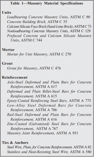
Mortar should comply with Standard Specification for Mortar for Unit Masonry, ASTM C 270 (ref. 9). In addition, most building codes require the use of Type M or S mortar for construction of basement walls (refs. 2, 4, 5, 9, 13), because Type M and S mortars provide higher compressive strengths. Table 1 lists mortar proportions.

Typical concrete masonry construction uses about 8.5 ft3 (0.24 m3) of mortar for every 100 ft2 (9.3 m2) of masonry wall area. This figure assumes 3/8 in. (9.5 mm) thick mortar joints, face shell mortar bedding, and a 10% allowance for waste.

Grout: In reinforced concrete masonry construction, grout is used to bond the reinforcement and the masonry together. Grout should conform to Standard Specification for Grout for Masonry, ASTM C 476 (ref. 10), with the proportions listed in Table 2. As an alternative to complying with the proportion requirements in Table 2, grout can be specified to have a minimum compressive strength of 2000 psi (13.8 MPa) at 28 days. Enough water should be added to the grout so that it will have a slump of 8 to 11 in. (203 to 279 mm). The high slump allows the grout to be fluid enough to flow around reinforcing bars and into small voids. This initially high water-to-cement ratio is reduced significantly as the masonry units absorb excess mix water. Thus, grout gains high strengths despite the initially high waterto-cement ratio.

Construction

Prior to laying the first course of masonry, the top of the footing must be cleaned of mud, dirt, ice or other materials which reduce the bond between the mortar and the footing. This can usually be accomplished using brushes or brooms, although excessive oil or dirt may require sand blasting.

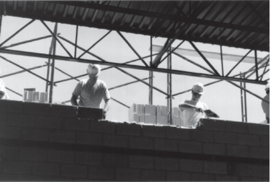
Masons typically lay the corners of a basement first so that alignment is easily maintained. This also allows the mason to plan where cuts are necessary for window openings or to fit the building’s plan.

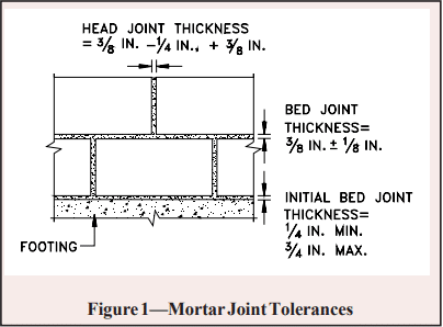
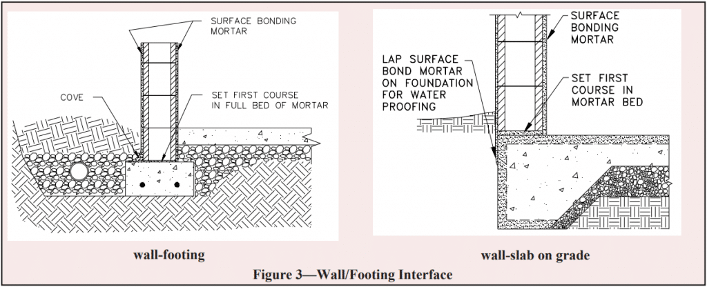
To make up for surface irregularities in the footing, the first course of masonry is set on a mortar bed joint which can range from 1/4 to 3/4 in. (6.4 to 19 mm) in thickness. This initial bed joint should fully bed the first course of masonry units, although mortar should not excessively protrude into cells that will be grouted.

All other mortar joints should be approximately 3/8 in. (9.5 mm) thick and, except for partially grouted masonry, need only provide face shell bedding for the masonry units. In partially grouted construction, webs adjacent to the grouted cells are mortared to restrict grout from flowing into ungrouted cores. Head joints must be filled solidly for a thickness equal to a face shell thickness of the units.

Tooled concave joints provide the greatest resistance to water penetration. On the exterior face of the wall, mortar joints may be cut flush if parging coats are to be applied.

When joint reinforcement is used, it should be placed directly on the block with mortar placed over the reinforcement in the usual method. A mortar cover of at least 5/8 in. (15.9 mm) should be provided between the exterior face of the wall and the joint reinforcement. A mortar cover of 1/2 in. (12.7 mm) is needed on the interior face of the wall. For added safety against corrosion, hot dipped galvanized joint reinforcement is recommended.

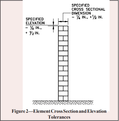
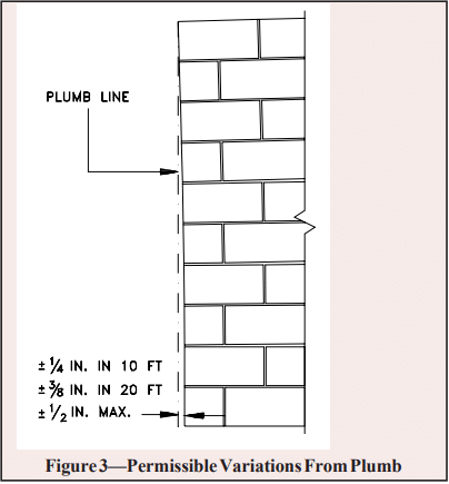
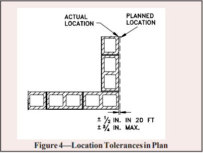
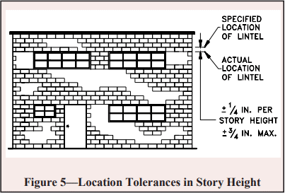
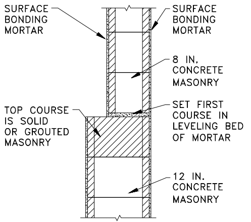
See Figures 1-4 for construction details.

Reinforced Masonry: For reinforced masonry construction, the reinforcing bars must be properly located to be fully functional. In most cases, vertical bars are positioned towards the interior face of basement walls to provide the greatest resistance to soil pressures. Bar positioners at the top and bottom of the wall prevent the bars from moving out of position during grouting. A space of at least 1/2 in. (12.7 mm) for coarse grout and 1/4 in. (6.4 mm) for fine grout should be maintained between the bar and the face shell of the block so that grout can flow completely around the reinforcing bars.

As mix water is absorbed by the units, voids can form in the grout. Accordingly, grout must be puddled or consolidated after placement to eliminate these voids and to increase the bond between the grout and the masonry units. Most codes permit puddling of grout when it is placed in lifts less than about 12 in. (305 mm). Lifts over 12 inches (305 mm) should be mechanically consolidated and then reconsolidated after about 3 to 10 minutes.

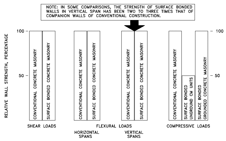
Surface Bonding: Another method of constructing concrete masonry walls is to dry stack units (without mortar) and then apply surface bonding mortar to both faces of the wall. The surface bonding mortar contains thousands of small glass fibers. When the mortar is applied properly to the required thickness, these fibers, along with the strength of the mortar itself, help produce walls of comparable strength to conventionally laid plain masonry walls. Surface bonded walls offer the benefits of excellent dampproof coatings on each face of the wall and ease of construction.

Dry-stacked walls should be laid in an initial full mortar bed to level the first course. Level coursing is maintained by using a rubbing stone to smooth small protrusions on the block surfaces and by inserting shims every two to four courses.

Water Penetration Resistance: Protecting below grade walls from water entry involves installation of a barrier to water and water vapor. An impervious barrier on the exterior wall surface can prevent moisture entry.

The barrier is part of a comprehensive system to prevent water penetration, which includes proper wall construction and the installation of drains, gutters, and proper grading.

Building codes (refs. 2, 4 , 5, 9, 13) typically require that basement walls be dampproofed for conditions where hydrostatic pressure will not occur, and waterproofed where hydrostatic pressures may exist. Dampproofing is appropriate where groundwater drainage is good, for example where granular backfill and a subsoil drainage system are present. Hydrostatic pressure may exist due to a high water table, or due to poorly draining backfill, such as heavy clay soils. Materials used for waterproofing are generally elastic, allowing them to span small cracks and accommodate minor movements.

When choosing a waterproof or dampproof system, consideration should be given to the degree of resistance to hydrostatic head of water, absorption characteristics, elasticity, stability in moist soil, resistance to mildew and algae, impact or puncture resistance, and abrasion resistance. A complete discussion of waterproofing, dampproofing, and drainage systems is included in TEK 19-03A (ref. 6).

All dampproofing and waterproofing systems should be applied to walls that are clean and free from dirt, mud and other materials which may reduce bond between the coating and the concrete masonry wall.

Draining water away from basement walls significantly reduces the pressure the walls must resist and reduces the possibility of water infiltration into the basement if the waterproofing (or dampproofing) system fails. Perforated pipe has historically proven satisfactory when properly installed. When placed on the exterior side of basement walls, perforated pipes are usually laid in crushed stone to facilitate drainage. To prevent migration of fine soil into the drains, filter fabrics are often placed over the gravel.

Drainage pipes can also be placed beneath the slab and connected into a sump. Pipes through the footing or the wall drain water from the exterior side of the basement wall.

The drainage and waterproofing systems should always be inspected prior to backfilling to ensure they are adequately placed. Any questionable workmanship or materials should be repaired at this stage since repairs are difficult and expensive after backfilling.

Backfilling: One of the most crucial aspects of basement construction is how and when to properly backfill. Walls should be properly braced or have the first floor in place prior to backfilling. Otherwise, a wall which is designed to be supported at the top may crack or even fail from the large soil pressures. Figure 5 shows one bracing scheme which has been widely used for residential basement walls. More substantial bracing may be required for high walls or large backfill pressures.

The backfill material should be free-draining soil without large stones, construction debris, organic materials, and frozen earth. Saturated soils, especially saturated clays, should generally not be used as backfill materials since wet materials significantly increase the hydrostatic pressure on the walls.

Backfill materials should be placed in several lifts and each layer should be compacted with small mechanical tampers. Care should be taken when placing the backfill materials to avoid damaging the drainage, waterproofing or exterior insulation systems. Sliding boulders and soil down steep slopes should thus be avoided since the high impact loads generated can damage not only the drainage and waterproofing systems but the wall as well. Likewise, heavy equipment should not be operated within about 3 feet (0.9 m) of any basement wall system.

The top 4 to 8 in. (102 to 203 mm) of backfill materials should be low permeability soil so rain water is absorbed into the backfill slowly. Grade should be sloped away from the basement at least 6 in. (152 mm) within 10 feet (3.1 m) of the building. If the ground naturally slopes toward the building, a shallow swale can be installed to redirect runoff.

Construction Tolerances

Specifications for Masonry Structures (ref. 8) specifies tolerances for concrete masonry construction. These tolerances were developed to avoid structurally impairing a wall because of improper placement.

  1. Dimension of elements in cross section or elevation
    …………………………………….¼ in. (6.4 mm), +½ in. (12.7 mm)
  2. Mortar joint thickness: bed………………………..+⅛ in. (3.2 mm)
    head………………………………..-¼ in (6.4 mm), + in. (9.5 mm)
  3. Elements
    • Variation from level: bed joints……………………………………….
      ±¼ in. (6.4 mm) in 10 ft (3.1 m), ±½ in. (12.7 mm) max
      top surface of bearing walls……………………………………………..
      ±¼ in.(6.4 mm), +⅜ in.(9.5 mm), ±½ in.(12.7mm) max
    • Variation from plumb………….±¼ in. (6.4 mm) 10 ft (3.1 m)
      ………………………………………±⅜ in. (9.5 mm) in 20 ft (6.1 m)
      ……………………………………………±½ in. (12.7 mm) maximum
    • True to a line…………………..±¼ in. (6.4 mm) in 10 ft (3.1 m)
      ………………………………………±⅜ in. (9.5 mm) in 20 ft (6.1 m)
      ……………………………………………±½ in. (12.7 mm) maximum
    • Alignment of columns and bearing walls (bottom versus top)
      ……………………………………………………………..±½ in (12.7 mm)
  4. Location of elements
    • Indicated in plan……………..±½ in (12.7 mm) in 20 ft (6.1 m)
      …………………………………………….±¾ in. (19.1 mm) maximum
    • Indicated in elevation
      ……………………………………….±¼ in. (6.4 mm) in story height
      …………………………………………….±¾ in. (19.1 mm) maximum

Insulation: The thermal performance of a masonry wall depends on its R-value as well as the thermal mass of the wall. Rvalue describes the ability to resist heat flow; higher R-values give better insulating performance. The R-value is determined by the size and type of masonry unit, type and amount of insulation, and finish materials. Depending on the particular site conditions and owner’s preference, insulation may be placed on the outside of block walls, in the cores of hollow units, or on the interior of the walls.

Thermal mass describes the ability of materials like concrete masonry to store heat. Masonry walls remain warm or cool long after the heat or air-conditioning has shut off, keeping the interior comfortable. Thermal mass is most effective when insulation is placed on the exterior or in the cores of the block, where the masonry is in direct contact with the interior conditioned air.

Exterior insulated masonry walls typically use rigid board insulation adhered to the soil side of the wall. The insulation requires a protective finish where it is exposed above grade to maintain durability, integrity, and effectiveness.

Concrete masonry cores may be insulated with molded polystyrene inserts, expanded perlite or vermiculite granular fills, or foamed-in-place insulation. Inserts may be placed in the cores of conventional masonry units, or they may be used in block specifically designed to provide higher R-values.

Interior insulation typically consists of insulation installed between furring strips, finished with gypsum wall board or panelling. The insulation may be fibrous batt, rigid board, or fibrous blown-in insulation.

Design Features

Interior Finishes: Split faced, scored, burnished, and fluted block give owners and designers added options to standard block surfaces. Colored units can be used in the entire wall or in sections to achieve specific patterns.

Although construction with staggered vertical mortar joints (running bond) is standard for basement construction, the appearance of continuous vertical mortar joints (stacked bond pattern) can be achieved by using of scored units or reinforced masonry construction.

Natural Lighting: Because of the modular nature of concrete masonry, windows and window wells of a variety of shapes and sizes can be easily accommodated, giving basements warm, natural lighting. For additional protection and privacy, glass blocks can be incorporated in lieu of traditional glass windows.

References

  1. Basement Manual-Design and Construction Using Concrete Masonry, CMU-MAN-002-01, Concrete Masonry & Hardscapes Association, 2001.
  2. BOCA National Building Code. Country Club Hills, IL: Building Officials and Code Administrators International, Inc. (BOCA), 1999.
  3. Building Code Requirements for Masonry Structures, ACI 530-02/ASCE 5-02/TMS 402-02. Reported by the Masonry Standards Joint Committee, 2002.
  4. International Residential Code. Falls Church, VA: International Code Council, 2000.
  5. International Building Code. Falls Church, VA: International Code Council, 2000.
  6. Preventing Water Penetration in Below-Grade Concrete Masonry Walls, TEK 19-03A. Concrete Masonry & Hardscapes Association, 2001.
  7. Seismic Design Provisions for Masonry Structures, TEK 14-18B, Concrete Masonry & Hardscapes Association, 2009.
  8. Specifications for Masonry Structures, ACI 530.1-02/ASCE 6-99/TMS 602-02. Reported by the Masonry Standards Joint Committee, 2002.
  9. Standard Building Code. Birmingham, AL: Southern Building Code Congress International, Inc. (SBCCI), 1999.
  10. Standard Specification for Grout for Masonry, ASTM C 476-01. American Society for Testing and Materials, 2001.
  11. Standard Specification for Load-Bearing Concrete Masonry Units, ASTM C 90-01. American Society for Testing and Materials, 2001.
  12. Standard Specification for Mortar for Unit Masonry, ASTM C 270-00. American Society for Testing and Materials, 2000.
  13. Uniform Building Code. Whittier, CA: International Conference of Building Officials (ICBO), 1997.

Evaluating Existing Concrete Masonry Construction

INTRODUCTION

The majority of quality control testing of concrete masonry materials is conducted on samples representative of those used in actual construction (ref. 1, 2, 3, and 4). In some cases, however, it may be necessary or desirable to evaluate the properties of existing masonry construction using the actual construction materials instead of representative samples. Examples where the in-place (in situ) masonry properties might need to be considered include old construction, damaged construction or during the construction process when:

  • a testing variable or construction practice fails to meet specifications;
  • a test specimen is damaged prior to testing;
  • test records are lost; or
  • representative samples are not otherwise available.

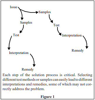
This TEK outlines guides and practices for the physical evaluation of masonry units, grout, mortar, and assemblies that form a part of an existing structure. Because no single procedure can be considered universally applicable for the evaluation and assessment of all conditions, proper tests or inspections must be selected with care as they form only a part of a broader evaluation, which may also include structural considerations, performance attributes, acceptance criteria, and goals (see Figure 1).

In some cases the physical characteristics of the materials or construction may not be in question, but instead concerns are focused on one or more performance attributes. While possibly stemming from any one of a number of sources, including poor construction, detailing, or materials; common performance related assessments include sources and causes of cracking, mitigating water penetration, and strength evaluation. Options for the evaluation and remediation of masonry structures are virtually endless. A thorough review of this subject can be found in reference 17.

MASONRY UNITS

When it is deemed necessary to remove units from a wall to evaluate their physical properties, the selection and removal of specimens should follow ASTM C 1420 Standard Guide for Selection, Removal, and Shipment of Manufactured Masonry Units Placed in Usage (ref. 5) to minimize potential damage to the units during their removal and transport and to obtain a representative sampling of specimens from which generalized conclusions can be drawn. Once removed, units can be sent to a laboratory for further assessment using visual techniques, petrographic techniques, or more common tests such those used in determining the compressive strength or equivalent thickness for fire resistant construction. Although comprehensive in its scope, ASTM C 1420 does not contain acceptance criteria or guidance for the interpretation of the results, as the application of such information is nearly always project specific.

While often definitive in their results when properly implemented and interpreted, the option of removing units from existing construction can have its limitations, especially when the existing construction is grouted or contains reinforcement. While it is still physically possible to remove a hollow unit that has been grouted and reinforced from a masonry wall, it becomes difficult (if not impossible) to determine the compressive strength of such units due to the presence of the grout and reinforcement. Hence, for construction that contains grout and/or reinforcement, it may be more appropriate to remove prisms or cores from the assembly, particularly when structural stability is the primary reason for the evaluation.

MORTAR

In many cases, the importance placed on the compressive strength of masonry mortars is overemphasized. Because the compressive strength of masonry mortars is not of principal concern in the overall performance of masonry structures there are no test methods that directly measure the compressive strength of mortar taken from an assembly. Yet, there may be circumstances when the removal and evaluation of mortar from existing masonry construction may be deemed necessary. ASTM C 1324 Standard Test Method for Examination and Analysis of Hardened Masonry Mortar (ref. 6) reviews procedures primarily related to the petrographic examination and chemical analysis of samples of masonry mortar removed from masonry construction. Based upon such examination and analysis, proportions of components in masonry mortars can be determined, which can then easily be compared to the volume proportions of ASTM C 270 (ref. 7) to classify a particular mortar or to document the actual proportions of materials used in the mortar.

While ASTM C 1324 can be an invaluable tool for measuring the relative amounts of constituent materials used in a mortar or in mapping the chemical makeup of a mortar, it does have its limitations. For example, even if a mortar is shown to have proportions that do not comply with the requirements of ASTM C 270, the mortar may still comply with the property requirements of C 270, which cannot be reasonably measured through examination of field mortars. Further, the information provided by C 1324 is anecdotal and highly subject to user error. Like all emerging technologies, results stemming from petrographic analyses should be subjected to critical review and careful interpretation.

GROUT

Unlike mortar and units, grout is often hidden from view once placed. Hence, evaluation methods that are focused on grout include both physical tests, such as measuring the compressive strength or grout/unit bond strength, as well as documenting proper placement and consolidation, to ensure as few voids as possible in the resulting construction.

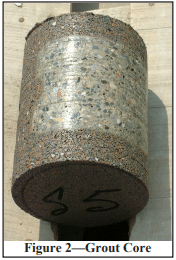
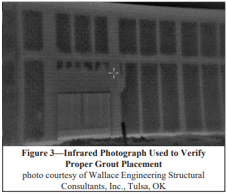
While following the grout lift height and pour height of Specification for Masonry Structures (ref. 8) is a prescriptive means of ensuring high quality grout placement, alternative grouting procedures, such as those permitted by Specification for Masonry Structures through the construction of a grout demonstration panel (refs. 8 and 9), may require supplementary means of documenting proper grout placement and consolidation. Obtaining physical specimens, such as grout cores (see Figure 2) or saw-cut samples (ref. 10), is one means of documenting proper grout placement when non-standardized grouting procedures are used, less destructive (and often less expensive) tests such as ultrasound, impact-echo and infrared photography can be highly efficient tools for measuring the subsurface characteristics of a masonry wall.

ASSEMBLIES

As with individual units, ASTM has published a guide for the selection and removal of masonry assemblies from existing construction, ASTM C 1532 (ref. 11). The procedures outlined in ASTM C 1532 are useful when physical examination of an assembly’s compressive strength, stiffness, flexural strength, or bond strength is needed on a representative sample of the actual construction (ref. 12). When conditions permit, or when less destructive means of evaluation are warranted, several testing alternatives are available.

Modulus of Elasticity

ASTM C 1197, Standard Test Method for In Situ Measurement of Masonry Deformability Properties Using the Flatjack Method, (ref. 13) can be used to evaluate the modulus of elasticity (stiffness) of a single wythe of unreinforced masonry constructed with solid units. To perform the test, two slots are cut into the mortar joints at the top and bottom of the section of masonry to be evaluated. Thin, bladder-like flatjack devices are inserted into these open mortar joints and then pressurized, inducing a controlled compressive stress on the masonry between them. Pressure in the flatjacks is gradually increased and the resulting masonry deformations are measured. The modulus of elasticity is calculated based on the resulting stress-strain relationship. Note that experimental and analytical investigations have indicated that this test typically overestimates the compressive modulus of masonry by up to 15 percent.

Mortar Joint Shear Strength

Guidelines for the Rehabilitation of Existing Buildings (ref. 14) contains a relationship between masonry bed joint shear strength measured in situ to the overall strength of a masonry shear wall. This relationship assumes the wall shear strength is limited by shear through the mortar joints rather than shear through the units. To measure the in situ mortar joint shear strength, ASTM C 1531, Standard Test Method for In Situ Measurement of Masonry Mortar Joint Shear Strength Index (ref. 15), is used. Included in ASTM C 1531 are three test methods for determining an index of the horizontal shear resistance of mortar bed joints in existing unreinforced solid-unit or ungrouted hollow-unit masonry.

In accordance with ASTM C 1531, the mortar bed joint shear strength index is determined by horizontally displacing a test unit relative to the surrounding masonry using a hydraulic jack or specialized flatjacks. The horizontal force required to displace the test unit provides a measured index of the mortar joint shear strength. Some studies have indicated that the in situ mortar joint shear strength may overestimate the actual shear strength index of a masonry wall. While a relationship has been established between the mortar joint shear strength and the shear strength of a masonry wall, there is currently insufficient data to define a similar correlation between the in situ measurement of bed joint shear strength and the actual bed joint shear strength.

Compressive Stress and Strength

For some engineering evaluations of existing masonry it may be necessary to estimate the compressive stress present in the wall. ASTM C 1196, Standard Test Method for In Situ Compressive Stress Within Solid Unit Masonry Estimated Using Flatjack Measurements (ref. 16), provides one such method to determine the average compressive stress in an unreinforced solid unit masonry wythe. The method uses flatjacks above and below the test region similar to ASTM C 1197 previously discussed. When the mortar joints above and below the test area are removed from the masonry to accommodate the flatjacks, the masonry deforms. The flatjack pressure required to move the masonry back to its original position is approximately equal to the compressive stress in the masonry.

The compressive strength of masonry can be evaluated by testing masonry prisms removed from the wall or by using cores cut from a grouted portion of the wall. If vertical reinforcement is present in the wall, testing a prism can be difficult because the vertical reinforcing steel carries load, hence the test is not a true evaluation of the masonry properties. In this case, cored samples may provide a better estimate, because the cores are tested in an orientation 90 degrees from the in situ position, so the reinforcing steel does not interfere with the test.

Limited research (ref. 10) on 6 inch (152-mm) diameter cores cut from grouted masonry compared the compressive strength of the core sample to that of masonry prisms constructed using the same materials. In these investigations, the average ratio of core to prism compressive strength was 1.04 for cores with an aspect ratio (height to diameter) of 1.27. Research on in situ masonry prism removal and testing (ref. 12) found a similar correlation factor when comparing both masonry prisms removed from existing construction to laboratory prepared prisms using similar materials.

NONDESTRUCTIVE EVALUATION

Obviously, the removal of units, prisms, cores, or other materials from a masonry structure is aesthetically detrimental and potentially structurally damaging. When possible, the physical evaluation of existing concrete masonry structures should provide the necessary information that results in the least cost and damage to the structure. A number of nondestructive evaluation procedures are applicable to masonry construction, which are often used in concert with the previously described test methods. The benefit of these techniques is the ability to evaluate portions of a structure with little or no damage.

Ultrasound and Impact-Echo

Ultrasound evaluations (pulse-velocity and pulse-echo) use a transmitter and receiver to pass ultrasonic energy through a wall. The density of the wall is estimated based on the velocity of the waves passing through the wall. Unlike the other methods discussed here, ultrasound requires access to both sides of the wall being evaluated.

Impact-echo differs in two ways from ultrasound: lower frequencies are used, which helps overcome the high signal attenuation and noise often encountered with ultrasound; and access to both sides of the wall is not required. Impact-echo uses elastic stress waves generated by a surface impact. These stress waves are reflected back to the receiver as they encounter internal anomalies or an exterior surface of the wall. Analysis of the reflected signal strength and shape allows evaluation of wall thickness and location of voids and grout areas.

Infrared

Infrared, or heat imaging, technologies measure thermal radiation from a wall surface, and record these emissions as different colors, corresponding to different surface temperatures (see Figure 3). Variations in temperature can be associated with factors such as wall solidity, moisture content, or a change in construction materials or insulation. Infrared cameras allow the user to survey an entire wall relatively quickly.

In order to provide a representative image of the wall, infrared measuring devices require heat to be transmitting through the wall (i.e., a warm interior and a relatively cool exterior ambient temperature). Generally, the larger the temperature flux, the better the resolution of subsurface anomalies.

Fiber Optics (Borescope and Fiberscope)

Borescopes (rigid optical scope) and fiberscopes (flexible optical scope) are useful for viewing interior void areas in a masonry wall. The scope is inserted into a small hole drilled into the wall, and can be attached to a camera or video recorder to document the observations. Borescopes and fiberscopes are often used to visually confirm anomalies detected using ultrasound, impact-echo or infrared methods, or to assess the condition of interior objects or cavities such as wall ties and collar joints.

Electromagnetic Devices (Rebar Locators)

Electromagnetic devices are commonly used to locate metal in masonry walls. Rebar locators generate a magnetic field, which is disturbed when a metallic object is encountered. The magnitude of the disturbance is related to the size of the object and its distance from the probe. Rebar locators can be used to: detect the location and orientation of reinforcing bars, prestress cables and other embedded metal items; measure the depth of embedded metal; and estimate the size of the metal items.

REFERENCES

  1. Evaluating the Compressive Strength of CM based on 2012IBC/2011 MSJC, TEK 18-01B. Concrete Masonry & Hardscapes Association, 2011.
  2. Sampling and Testing Concrete Masonry Units, TEK 1802C. Concrete Masonry & Hardscapes Association, 2014.
  3. Concrete Masonry Inspection, TEK 18-03B, Concrete Masonry & Hardscapes Association, 2014.
  4. Masonry Mortar Testing, TEK 18-05B, Concrete Masonry & Hardscapes Association, 2014.
  5. Standard Guide for Selection, Removal, and Shipment of Manufactured Masonry Units Placed in Usage, ASTM C 1420-99, ASTM International, 1999.
  6. Standard Test Method for Examination and Analysis of Hardened Masonry Mortar, ASTM C 1324-02a, ASTM International, 2002.
  7. Standard Specification for Mortar for Unit Masonry, C 270-02. ASTM International, 2002.
  8. Specification for Masonry Structures, ACI 530.1-02/ASCE 6-02/TMS 602-02. Reported by the Masonry Standards Joint Committee, 2002.
  9. Grouting Concrete Masonry Walls, TEK 03-02A, Concrete Masonry & Hardscapes Association, 2005.
  10. Research Evaluation of Various Grout Consolidation Techniques in Concrete Masonry, MR-13, Concrete Masonry & Hardscapes Association, 1999.
  11. Standard Guide for Selection, Removal, and Shipment of Masonry Assemblage Specimens from Existing Construction, ASTM C 1532-02, ASTM International, 2002.
  12. Research Evaluation of the Compressive Strength of In Situ Masonry, MR-8, Concrete Masonry & Hardscapes Association, 1993.
  13. Standard Test Method for In Situ Measurement of Masonry Deformability Properties Using the Flatjack Method, ASTM C 1197-03, ASTM International, 2003.
  14. Guidelines for the Rehabilitation of Existing Buildings, International Code Council, 2000.
  15. Standard Test Method for In Situ Measurement of Masonry Mortar Joint Shear Strength Index, ASTM C 1531-03, ASTM International, 2002.
  16. Standard Test Method for In Situ Compressive Stress Within Solid Unit Masonry Estimated Using Flatjack Measurements, ASTM C 1196-03, ASTM International, 2003.
  17. Nondestructive Evaluation and Testing of Masonry Structures, Suprenant, B.A., Schuller, M.P., Hanley-Wood, 1994.


Masonry Mortar Testing

INTRODUCTION

Masonry mortars are composed of cementitious materials, aggregates, water, and admixtures when specified. Cementitious materials include portland cement, masonry cement, mortar cement, slag cement, blended hydraulic cement, hydraulic cement, quicklime, hydrated lime and lime putty. Aggregates consist of natural sand or manufactured sand. Admixtures may include such materials as coloring pigments, water repellent agents, accelerators, retarders and air-entraining agents. These materials are described in Mortars for Concrete Masonry, TEK 09-01A (ref. 1).

Quality assurance testing of site-prepared mortar is fairly uncommon, except on large jobs or for essential facilities. When mortar testing is required, it is essential that all parties involved possess a thorough knowledge of the mortar specifications, test methods and standard industry practices. Misinterpretations of these standards can result in improper testing and confusion regarding compliance with specifications.

Typically, project specifications require mortar to comply with Standard Specification for Mortar for Unit Masonry, ASTM C270 (ref. 2). Two methods of demonstrating compliance with ASTM C270 are permitted: the proportion specification or the property specification. Note that these compliance options are completely independent of each other; the requirements from one should not be used in conjunction with the other. Of the two options, the proportion specification is much more commonly used. TEK 09-01A covers the proportion specification in detail.

Although physical testing of the mortar is not required to demonstrate compliance with the proportion specification, the mortar is often tested to verify consistency throughout the job, most often by cone penetration or compressive strength testing. The property specification requires testing to be performed on laboratory-prepared mortar to demonstrate compliance with a specified minimum compressive strength, minimum water retention and maximum air content. This information is required for submittals, so is performed prior to construction. Where special inspection is required in accordance with the International Building Code (ref. 3), the special inspector, as part of his duties, is required to verify compliance with the approved mix proportions for field-prepared mortar. Both consistency testing and testing to verify compliance with the property specification are covered in this TEK.

Field-prepared and preconstruction mortar should be evaluated using Standard Test Method for Preconstruction and Construction Evaluation of Mortars for Plain and Reinforced Unit Masonry, ASTM C780 (ref. 4), which includes the following test methods: consistency by cone penetration; consistency retention by cone penetration; consistency by modified concrete penetrometer; mortar-aggregate ratio and water content; air content; and compressive strength. Note that mortar compressive strength is not an accurate indication of mortar strength in the wall, nor of the masonry wall compressive strength. This is discussed in detail in the section Compressive Strength Testing of Field-Prepared Mortar, below.

Note that the physical properties of these field mortar evaluations cannot be compared to the values required by the ASTM C270 property specification. In fact, ASTM does not publish minimum compressive strength requirements for field-prepared mortar.

When fresh mortar is placed on concrete masonry units during construction, its characteristics immediately begin to change due to water absorption by the masonry units. Nearly all of the available mortar test methods, however, are performed on mortar before it comes into contact with masonry units. Therefore, the properties of the sampled and tested mortar can be expected to differ significantly from mortar in contact with masonry units. Because conditions of the units and environment can vary greatly from job to job, the properties of the plastic mortar may need to vary as well to ensure quality construction. For this reason, no pass/fail criteria exist for field tests of mortar.

Standard Guide for Quality Assurance of Mortars, ASTM C1586 (ref. 5) provides guidance on the proper use of ASTM C270 and C780 for evaluating masonry mortar produced in the laboratory and at the construction site.

MORTAR CONSISTENCY

The most important aspect of mortar quality control is consistency throughout the construction project. The test methods outlined in ASTM C780 are intended to evaluate that consistency. Test results acquired throughout construction are compared to a baseline preconstruction evaluation.

The cone penetration test offers a quantitative measure of mortar consistency. Test values indicate the mortar workability, which may be affected by water content, aggregate properties, batch properties and other factors. Tested values are likely to change throughout a project’s duration due to variable site conditions as well as variations in masonry unit moisture content and absorption characteristics.

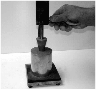
Cone penetration tests are performed by dropping a conical plunger from a specified height into a measured mortar sample and measuring the resulting depth of penetration, as shown in Figure 1.

MORTAR AGGREGATE RATIO

Mortar quality assurance often includes verification that mortar materials are proportioned as specified. ASTM C780 Annex A4 provides a method for sampling mortar from the field and determining the ratio of aggregate to cementitious material in the sample by weight. The mortar sample is passed through a No. 100 (150-µm) sieve to determine the percentage of material coarser than 150-µm. These results are compared to a sieve analysis of the aggregate used in the mortar to determine what fraction of the material passing the sieve is aggregate, and what fraction is cementitious material.

To complete the calculations in the test method, the mortar water content must also be determined, as detailed in Annex A4.

MORTAR COMPRESSIVE STRENGTH TESTING

One of the most universally recognized properties of masonry is compressive strength. While this property may not be the most important for masonry mortar, it is often perceived as such because compressive strength values are generally understood and are relatively easy to determine. Confusion and misinterpretation sometimes exist, however, when interpreting project specification requirements for mortar strength because there are several different compressive strength test methods included in ASTM Standards and model building codes. These methods were established to address specific needs, and they differ from each other in test requirements for obtaining, conditioning and testing mortar samples and specimens. Note that the mortar compressive strength determined in a laboratory is not indicative of either the strength of the mortar in the wall, nor of the masonry (i.e., wall) compressive strength. Specification for Masonry Structures (ref. 6) includes two alternatives for documenting masonry compressive strength; one based on the type of mortar and the compressive strength of the masonry units; the other based on compression testing of masonry prisms.

Compressive Strength Testing of Laboratory-Prepared mortar

Verifying compliance to the ASTM C270 property specification requires mortar compressive strength to be tested in accordance with Standard Test Method for Compressive Strength of Hydraulic Cement Mortars (Using 2-in. or 50-mm Cube Specimens), ASTM C 109 (ref. 7), with modifications regarding specimen storage and conditioning.

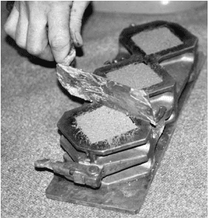
Compressive strength testing in accordance with ASTM C270 is conducted on specimens that are proportioned, mixed and conditioned in the testing laboratory. Water content of the mortar sample is such that the mortar flow must be 110 ± 5%. Compressive strength test specimens are 2 in. (51 mm) mortar cubes cast in nonabsorbent molds (see Figure 2) and cured in a moist room or moist cabinet meeting the requirements of ASTM C511, Standard Specification for Mixing Rooms, Moist Cabinets, Moist Rooms and Water Storage Tanks Used in the Testing of Hydraulic Cements and Concretes (ref. 9), until tested.

ASTM test methods emphasize the importance of extreme care in observing the testing procedures used to verify C270 requirements. According to Note 8 of ASTM C109: “Reliable strength results depend upon careful observance of all the specified requirements and procedures. Erratic results at a given test period indicate that some of the requirements and procedures have not been carefully observed, for example, those covering the testing of the specimens as prescribed in 10.6.2 and 10.6.3. Improper centering of specimens resulting in oblique fractures or lateral movement of one of the heads of the testing machine during loading will cause lower strength results.”

To facilitate centering the test specimens, the compression testing machine is required to have a spherically-seated upper bearing block attached at the center of the upper head. The bearing surface diagonal or diameter is required to be only slightly greater than the diagonal or diameter of the specimen.

Compressive Strength Testing of Field-Prepared Mortar

Compressive strength is one of the most commonly tested properties of field mortar. The test, described in ASTM C780, provides an indication of mortar consistency during construction, not as an indication of the compressive strength of the masonry, or even of the mortar in the wall. Compressive strength test results should be compared on a periodic basis to evaluate uniformity. These test results can be compared to preconstruction test results of similarly prepared mortar to provide a reference to a preapproved laboratory-prepared mortar strength.

Knowledgeable interpretations of results are necessary. As an example, consider the mortar’s water to cement ratio, which can have a significant effect on the tested strength. Mortar on site is adjusted to accommodate field conditions: on a hot sunny day, the mason may desire a more plastic mortar with a higher water content. Mortar sampled on this day will have a lower tested compressive strength than a similar mortar sampled on a cooler, damper day, which would likely be mixed using less water. However, the end result—the condition of the mortar in the wall—may be very comparable. These factors must be accounted for when interpreting compressive strength test results of field-prepared mortar.

Note that the results of these evaluations are not representative of the strength of the mortar in the wall, rather, they represent approximate mortar strengths only. The tested compressive strength of field-mixed mortar may be significantly less than that of hardened mortar joints for several reasons.

  • Mortar specimens are cast in nonabsorbent forms, whereas mortar in the wall is exposed to the suction from absorbent masonry units, reducing the water to cement ratio, which in turn increases the compressive strength.
  • The aspect ratio of the test specimens is greater than that of mortar joints. The typical mortar joint, at in. (9.5 mm) high with a depth of at least 1 in. (25 mm), results in a broad, stable configuration that is naturally able to carry more load than the comparatively taller and more slender mortar specimens used for material evaluation. When tested at an aspect ratio of :1, tested mortar compressive strength values are routinely 8,000 to 10,000 psi (55.16 to 68.95 MPa).

For these reasons as well as others, field mortar compressive strength test results should never be compared to the requirements in ASTM C270 Table 2, which apply to laboratory-prepared mortar only.

ASTM C780 permits the use of cube or cylinder molds. Cylinder molds of 2 or 3 in. (51 or 76 mm) diameter have heights twice their diameter. Due to the higher aspect ratio of cylinder specimens, tests on cylindrical specimens result in tested compressive strength values approximately 15% less than those of cube specimens of the same mortar. If cylinder test results are to be directly compared to those for cubes, correction factors should be applied to the cylinder specimen results.

Immediately after sampling the mortar, it is placed in the molds, consolidated and covered to prevent evaporation per the procedures dictated by C780. The filled molds are stored for 24 hours in conditions as close to laboratory conditions as possible, at which point they are transported to the laboratory and stored in a moist room for another 24 hours. The specimens are then stripped of their molds and stored in the moist room or closet until 2 hours prior to compressive strength testing.

Prior to testing, mortar cylinders are capped with a gypsum or sulfur capping compound to provide uniform parallel bearing surfaces. Mortar cubes, however, are tested without caps, as the molded cube surfaces provide a smooth and uniform bearing surface. The specimens are tested in a moist condition. The axis of the specimen is aligned with the center of thrust of the spherically-seated (upper) bearing block of the compression machine. Load is applied to the specimen continuously and without shock until failure, and the compressive strength, type of failure, and appearance of the mortar is reported.

Uniform Building Code Standard 21-16, Field Test Specimens For Mortar (ref. 10), contained another method to obtain mortar compressive strength test specimens. This method prescribes ½ to in. (13 to 16 mm) thickness of mortar to be spread on a masonry unit and allowed to stand for one minute. The mortar is then removed from the unit and placed in a cube or cylinder for compressive strength testing. The test method, however, is no longer used or referenced in current codes and standards and would not provide results that can be compared to C270 properties.

WATER RETENTION

The property specification of ASTM C270 requires a minimum water retention of 75% when tested in accordance with Standard Test Method for Water Retention of Hydraulic Cement-Based Mortars and Plasters, ASTM C1506 (ref. 15). This test was developed to measure the ability of a mortar to retain its mix water under the suction of the adjacent masonry unit. A certain amount of water absorption by the unit is beneficial, but too much may be detrimental.

Water retention is determined in the laboratory by measuring the mortar’s “initial flow,” and “flow after suction.” Initial flow is the percent increase in diameter of a mortar sample when it is placed on a flow table and dropped 25 times in 15 seconds. The same procedure is used to determine flow after some of the mortar’s mix water has been removed by an applied vacuum, which is meant to simulate the suction of masonry units on mortar. Water retention is the ratio of flow after suction to initial flow, expressed as a percentage.

AIR CONTENT

The ASTM C270 property specification includes a limit on the mortar air content. In general, greater air contents result in greater mortar durability and workability, but reduced mortar bond strength.

Air content is determined in accordance with ASTM C91, with the exception that the laboratory-prepared mortar is required to be of the materials and proportions used in the construction. The air content of the mortar is determined by calculation using the weight of a sample of mortar and accounting for all of the materials used. The calculation requires precise measurements of all materials and a knowledge of the specific gravity of those materials.

ASTM C780 also includes procedures for determining mortar air content using a pressure or volumetric method, either of which can be used in repetitive tests to evaluate the effects of changes in mixing time, mixing procedures, or other variables.

FLEXURAL BOND STRENGTH

ASTM C1329 Standard Specification for Mortar Cement (ref. 11) covers additional requirements for masonry mortars using mortar cement as a cementitious material. Although mortar cement is similar to masonry cement, it must achieve a minimum bond strength and must meet a lower air content than masonry cement. Mortar cement is permitted to be used in buildings assigned to Seismic Design Categories D, E or F, whereas masonry cement and Type N mortar cannot be used as part of the lateral force-resisting system for these buildings (ref. 12). Compliance testing for flexural bond strength is conducted in accordance with ASTM C1072 Standard Test Method for Measurement of Masonry Flexural Bond Strength (ref. 13). This method relies in turn on Standard Test Methods for Evaluating Masonry Bond Strength, ASTM C1357 (ref. 14). C1357 uses a prism constructed of “standard masonry units,” defined for this use as solid 3 x 2¼ x 7 in. (92 x 57 x 194 mm) units. Mortar bond is determined by calculating the modulus of rupture based on wrenching units from the prism using a bond wrench testing apparatus. C1072 includes detailed requirements for aggregates, mix design, manufacturing, size, curing and moisture content of the “standard” concrete masonry units used to determine compliance.

REFERENCES

  1. Mortars for Concrete Masonry, TEK 09-01A. Concrete Masonry & Hardscapes Association, 2004.
  2. Standard Specification for Mortar for Unit Masonry, ASTM C270-14. ASTM International, Inc., 2014.
  3. International Building Code. International Code Council, 2012.
  4. Standard Test Method for Preconstruction and Construction Evaluation of Mortars for Plain and Reinforced Unit Masonry, ASTM C780-14. ASTM International, Inc., 2014.
  5. Standard Guide for Quality Assurance of Mortars, ASTM C1586-05(2011). ASTM International, Inc., 2011.
  6. Specification for Masonry Structures, TMS 602-13/ACI 530.1-13/ASCE 6-13. Reported by the Masonry Standards Joint Committee, 2013.
  7. Standard Test Method for Compressive Strength of Hydraulic Cement Mortars (Using 2-in. or 50-mm Cube Specimens), ASTM C109/C109M-13. ASTM International, Inc., 2013.
  8. Standard Specification for Masonry Cement, ASTM C91/C91M-12. ASTM International, Inc., 2012.
  9. Standard Specification for Mixing Rooms, Moist Cabinets, Moist Rooms and Water Storage Tanks Used in the Testing of Hydraulic Cements and Concretes, ASTM C511-13. ASTM International, Inc., 2013.
  10. Field Test Specimens for Mortar, UBC Standard 21-16, International Conference of Building Officials, 1994.
  11. Standard Specification for Mortar Cement, ASTM C1329/C1329M-12. ASTM International, Inc., 2012.
  12. Building Code Requirements for Masonry Structures, TMS 402-13/ACI 530-13/ASCE 5-13. Reported by the Masonry Standards Joint Committee, 2013.
  13. Standard Test Method for Measurement of Masonry Flexural Bond Strength, ASTM C1072-13e1. ASTM International, Inc., 2013.
  14. Standard Test Methods for Evaluating Masonry Bond Strength, ASTM C1357-09. ASTM International, Inc., 2009.
  15. Standard Test Method for Water Retention of Hydraulic Cement-Based Mortars and Plasters, ASTM C1506-09. ASTM International, Inc., 2009.

Mortars for Concrete Masonry

INTRODUCTION

While mortar represents only a small proportion of the total wall area in concrete masonry construction (approximately 7 percent), its influence on the performance of a wall is significant. Mortar serves many important functions: it bonds units together into an integral structural assembly, seals joints against penetration by air and moisture, accommodates small movements within a wall, accommodates slight differences between unit sizes, and bonds to joint reinforcement, ties and anchors so that all elements perform as an assembly.

MORTAR MATERIALS

The American Society for Testing and Materials (ASTM) maintains national standards for mortars and materials commonly used in mortars, as follows:

Portland cement (ASTM C 150, ref. 4d) is a hydraulic cement (sets and hardens by chemical reaction with water) and is one of the main constituents of mortar. Types I (normal), II (moderate sulfate resistance), and III (high early strength) are permitted according to ASTM C 270 (ref. 4f). Air-entrained portland cements (IA, IIA, and IIIA) may be used as alternatives to each of these types.

Masonry cement (ASTM C 91, ref. 4b) is a hydraulic cement consisting of a mixture of portland cement or blended hydraulic cement and plasticizing materials (such as limestone, hydrated or hydraulic lime) together with other materials introduced to influence such properties as setting time, workability, water retention, and durability. Masonry cements are classified as Type M, Type S, or Type N according to ASTM C 270. In addition, Type N masonry cement can be combined with portland cement or blended hydraulic cement to produce Type S or M mortars.

Mortar cement (ASTM C 1329, ref. 4j) is a hydraulic cement similar to masonry cement, with the added requirement of a minimum bond strength requirement.

Blended hydraulic cements (ASTM C 595, ref. 4g) consist of standard portland cement or air-entrained portland cement (denoted by -A) combined through blending with such materials as blast furnace slag (S), or pozzolan (P & PM) which is usually fly ash. Types IS, IS-A, IP, IP-A, I(PM), or I(PM)-A blended cements may be used as alternatives to portland cement to produce ASTM C 270 compliant mortars. Types S or SA (slag cement) may also be used in mortars meeting the property specification requirements of ASTM C 270 (Table 2 of this TEK).

Quicklime (ASTM C 5, ref. 4a) is calcined (burneddecarbonated) limestone, the major constituents of which are calcium oxide (CaO) and magnesium oxide (MgO). Quicklime must be slaked (combined chemically with water) prior to use. The resultant lime putty must be stored and allowed to hydrate for at least 24 hours before use. Consequently, quicklime is rarely used in mortar.

Hydrated lime (ASTM C 207, ref. 4e) is a dry powder obtained by treating quicklime with enough water to satisfy its chemical affinity for water. ASTM C 207 designates Type N (normal), Type S (special), and air-entraining Type NA and Type SA hydrated limes. Slaking of hydrated lime is not required, thus hydrated lime is immediately usable and much more convenient than quicklime. ASTM C 207 limits the amount of unhydrated oxides in Type S or Type SA hydrated limes, assuring the soundness of mortar made using these limes. Types N or NA lime are not typically used in mortar; however, they are permitted if shown by test or performance record to not be detrimental to the soundness of the mortar. Air-entrained limes are only permitted in mortars containing nonair-entrained cement.

Aggregates (ASTM C 144, ref. 4c) for mortar consist of either natural or manufactured sand. Manufactured sand is the product obtained by crushing stone, gravel, or air cooled blast furnace slag. It is characterized by sharp, angular shaped particles. Gradation limits are established in ASTM C 144 for both natural and manufactured sands. Aggregates which fail these gradation limits may be used, as long as the resulting mortar complies with the property specification requirements of ASTM C 270, as shown in Table 2.

Water for masonry mortar (ASTM C 270, ref. 4f) must be clean and free of deleterious amounts of acids, alkalis, or organic materials. Potability of water is not in itself a consideration, but the water obtained from drinking supply sources is considered suitable for use.

Admixtures (also sometimes called modifiers or additives) for masonry mortars (ASTM C 1384, ref. 4k) are available for various purposes. Admixtures are functionally classified as bond enhancers, workability enhancers, set accelerators, set retarders, and water repellents. Since chlo-rides accelerate the corrosion of steel reinforcement and accessories ASTM C 1384 stipulates that admixtures add not more than 65 ppm (0.0065%) water-soluble chloride or 90 ppm (0.0090%) acidsoluble chloride by weight of portland cement. Similarly, the Specifications for Masonry Structures (ref. 3) limits admixtures to no more than 0.2% chloride ions. The document also limits pigments for coloring to no more than 1 to 10% by weight of cement depending upon the pigment type.

Effect of Materials on Mortar

With the diversity of materials available, masonry mortars can be formulated to produce the desired properties for most specific job requirements. Each of the individual ingredients (cement, lime, sand, water, and any modifiers present) contributes to the performance of the mortar. Portland cement provides strength and durability. Lime imparts workability, water retention, as well as some limited cementitious and autogenous healing properties. Sand acts as a filler and provides body to the mortar while helping to reduce shrinkage and control cracking. Water acts as a mixing agent, a lubricant, and is also needed for hydration of the portland cement.

The various material options alter the characteristics of the mortar in a predictable manner. Changes in cement type promote slight changes in setting characteristics, workability, color, and strength development. Use of air-entrained cement or lime generally results in decreased water demand, improved workability, increased freeze thaw resistance, and decreased bond strength. Masonry cements, used singly or in combination with portland cement, provide mortars with excellent workability and freeze-thaw durability; however, bond strengths may be reduced. Consequently, design allowable flexural tension values vary based on mortar type and cementitious materials or lime used for unreinforced masonry (ref. 1).

Changes in sand type and gradation affect mortar properties. Natural sand gives improved workability at a lower water demand because of the spherical particle shape, while manufactured sands require additional water due to their angular shape. In general, well graded aggregates reduce segregation in a plastic mortar, which in turn inhibits bleeding and improves workability. Sands deficient in fines generally produce harsh mortars, while sands with excessive fines typically result in mortars with lower compressive strengths.

TYPES OF MORTAR

Building codes generally specify mortar types as referenced in ASTM C 270, Standard Specification for Mortar for Unit Masonry (ref. 4f). Four mortar types, M, S, N and O are included in this standard. However, Types M, S, and N are typically required by building codes. Building codes also may restrict the use of some mortars for particular applications. For example, empirical design of foundation walls requires Type M or S mortar and glass unit masonry requires Type N or S mortar (ref. 1). In seismic design categories , D, E, and F portland cement/ lime or mortar cement mortar Types S or M are required (ref. 1).

PROPORTIONING MORTAR

All mortar types are governed by either of the two specifications contained in ASTM C 270: the proportion specification or the property specification. Only one of the specifications should be called for in the project documents, not both. The proportion specification (Table 1) prescribes the parts by volume of each ingredient required to provide a specific mortar type. A combination of portland cement and lime may be used as the cementing agent in each type of mortar. Also, masonry cements (ref. 4b) or mortar cements (ref. 4j) are available that meet the requirements of M, S, and N mortars with or without further addition of cement.

As an alternative, approved materials may be mixed in controlled percentages as long as the resultant mortar meets the physical requirements designated in ASTM C 270, as shown in Table 2. The aggregate ratio noted in Table 2 must be followed. Conformance to the property specification of ASTM C 270 is established by testing laboratory prepared mortar during a pre-construction evaluation of the mortar proposed for the project. The laboratory then establishes proportions for mortar, based on successful tests. These proportions are then followed when preparing field mortar.

MASONRY MORTAR PROPERTIES

Many properties of mortar are not precisely definable in quantitative terminology because of a lack of definitive standards by which to measure them. For example, mortars can be rated on the basis of obtaining visually satisfactory mortar joints.

Depending on the particular circumstances for a given project, the criteria for mortar selection are based on design considerations, mortar properties in the plastic state or mortar properties in a hardened state. Consideration of each is necessary to achieve a desired result.

Properties of Plastic Mortar

Workability is the property of mortar characterized by the smooth plastic consistency which makes it easy to spread. This is the property of most importance to the mason. A workable mortar spreads easily under the trowel; adheres to vertical surfaces during unit handling, placement, and bedding; maintains alignment as other units are positioned; and provides a watertight, closed joint when tooled.

Once mix proportions have been established, the addition of water should be consistent with that required to improve mortar placement without sacrificing the ability to support the masonry unit. Adequate water content promotes intimate contact between the unit and mortar, which is essential for satisfactory bond. While water content has the greatest influence on the workability of a mortar, cementitious materials, aggregate gradation, and air-entrainment also contribute to a lesser degree.

Water retention of mortar is a measure of the mortar’s ability to retain its plasticity when subjected to the atmosphere or the absorptive forces of a concrete masonry unit. Mortars with low water retention stiffen more quickly, making it difficult for the mason to bed and adjust the masonry unit during placement. Mortars with desired water retention characteristics allow the mason to lay a mortar bed two or three units ahead before placing subsequent units. Water retentivity is dependent on properties of the cementitious materials, sand gradation, and mortar proportions.

The time lapse between spreading a mortar bed and placing block should be kept to a minimum, because the workability will be reduced as water is absorbed into the block. If too much time elapses before a block is placed on a fresh mortar bed, units are less easily positioned and the bond will be reduced.

Evaporation of the mixing water from mortar may require retempering (mixing in additional water). This generally is not harmful as long as it is done prior to hydration of the mortar. To avoid the stiffening effects of hydration, mortar must be placed in final position within 21/2 hours after the original mixing (ref. 3) unless special set retarding admixtures are used.

Properties of Hardened Mortar

Properties of hardened mortar that affect the performance of the finished concrete masonry include bond, compressive strength, and durability. These properties are difficult to measure other than in laboratory or field specimens prepared under controlled conditions. However, ASTM C 1324, Standard Test Method for Examination and Analysis of Hardened Masonry Mortar, (ref. 4i) provides procedures for petrographic examination and chemical analysis for components of masonry mortar in the hardened state. A 0.35 oz. (10 g) sample is usually sufficient for both the petrographic and chemical analysis. When obtaining the sample, however, it is important to ensure that the sample is representative of the mortar in question, i.e. original mortar as opposed to pointing mortar or other mortars used on the project.

Bond is a term used to describe both the extent of contact between mortar and unit and the strength of adhesion. Bond is a function of several factors including mortar properties, unit surface characteristics, workmanship, and curing. Other factors being equal, bond strength will increase as the compressive strength of the mortar increases, although not in direct proportion. Bond may also be effectively increased through the use of properly designed mortars having water contents which provide good workability.

Compressive strength is perhaps the most commonly measured property of mortar but is perhaps the most misunderstood. Whenever compressive strength results are intended to be used to determine conformance of a mortar to the property specifications of ASTM C 270, compressive strength tests must be conducted in accordance with the laboratory procedures required by ASTM C 270. However, field mortar compressive testing is to be conducted in accordance with ASTM C 780, Standard Test Method for Preconstruction and Construction Evaluation of Mortars for Plain and Reinforced Unit Masonry, (ref. 4h) and is only to verify the consistency of materials and procedures, not to determine mortar strength (ref. 3). ASTM C 780 contains no requirement for minimum compressive strength of field mortar. The the mortar strength in the wall will be much higher than the field test because of the reduced water cement ratio due absorption of mix water into the masonry units and a greatly reduced shape factor in the mortar joint versus the mortar test cube. ASTM C 780 recognizes this and states that the strength should not be construed as being representative of the actual strength of the mortar.

Durability of mortar also is an important consideration for parapets or other walls with an extreme exposure to the weather. Oversanding or overtempering can decrease durability. High strength mortars and air entrained mortars provide increased durability. For more detailed discussion on field testing of mortar see TEK 18-05B, Masonry Mortar Testing (ref. 2).

REFERENCES

  1. Building Code Requirements for Masonry Structures, ACI 530-02/ASCE 5-02/TMS 402-02. Reported by the Masonry Standards Joint Committee, 2002.
  2. Masonry Mortar Testing, TEK 18-05B, Concrete Masonry & Hardscapes Association, 2014.
  3. Specifications for Masonry Structures, ACI 530.1-02/ASCE 6-02/TMS 602-02. Reported by the Masonry Standards Joint Committee, 2002.
  4. 2004 Annual Book of ASTM Standards, American Society for Testing and Materials:
    4a. C 5-03, Standard Specification for Quicklime for Structural Purposes.
    4b. C 91-03a, Standard Specification for Masonry Cement.
    4c. C 144-03, Standard Specification for Aggregate for Masonry Mortar.
    4d. C 150-04, Standard Specification for Portland Cement.
    4e. C 207-04, Standard Specification for Hydrated Lime for Masonry Purposes.
    4f. C 270-03b, Standard Specification for Mortar for Unit Masonry.
    4g. C 595-03, Standard Specification for Blended Hydraulic Cements.
    4h. C 780-02, Standard Test Method for Preconstruction and Construction Evaluation of Mortars for Plain and Reinforced Unit Masonry.
    4i. C 1324-03, Standard Test Method for Examination and Analysis of Hardened Masonry Mortar.
    4j. C 1329-04, Standard Specification for Mortar Cement.
    4k. C 1384-03, Standard Specification for Admixtures for Masonry Mortars.

Estimating Concrete Masonry Materials

INTRODUCTION

Estimating the quantity or volume of materials used in a typical masonry project can range from the relatively simple task associated with an unreinforced single wythe garden wall, to the comparatively difficult undertaking of a partially grouted multi-wythe wall coliseum constructed of varying unit sizes, shapes, and configurations.

Large projects, due to their complexity in layout and detailing, often require detailed computer estimating programs or an intimate knowledge of the project to achieve a reasonable estimate of the materials required for construction. However, for smaller projects, or as a general means of obtaining ballpark estimates, the rule of thumb methods described in this TEK provide a practical means of determining the quantity of materials required for a specific masonry construction project.

It should be stressed that the information for estimating materials quantities in this section should be used with caution and checked against rational judgment. Design issues such as non-modular layouts or numerous returns and corners can significantly increase the number of units and the volume of mortar or grout required. Often, material estimating is best left to an experienced professional who has developed a second hand disposition for estimating masonry material requirements.

ESTIMATING CONCRETE MASONRY UNITS

Probably the most straightforward material to estimate for most masonry construction projects is the units themselves. The most direct means of determining the number of concrete masonry units needed for any project is to simply determine the total square footage of each wall and divide by the surface area provided by a single unit specified for the project.

For conventional units having nominal heights of 8 in. (203 mm) and nominal lengths of 16 in. (406 mm), the exposed surface area of a single unit in the wall is 8/9 ft2 (0.083 m 2). Including a 5 percent allowance for waste and breakage, this translates to 119 units per 100 ft2 (9.29 m2) of wall area. (See Table 1 for these and other values.) Because this method of determining the necessary number of concrete masonry units for a given project is independent of the unit width, it can be applied to estimating the number of units required regardless of their width.

When using this estimating method, the area of windows, doors and other wall openings needs to be subtracted from the total wall area to yield the net masonry surface. Similarly, if varying unit configurations, such as pilaster units, corner units or bond beam units are to be incorporated into the project, the number of units used in these applications need to be calculated separately and subtracted from the total number of units required.

ESTIMATING MORTAR MATERIALS

Next to grout, mortar is probably the most commonly misestimated masonry construction material. Variables such as site batching versus pre-bagged mortar, mortar proportions, construction conditions, unit tolerances and work stoppages, combined with numerous other variables can lead to large deviations in the quantity of mortar required for comparable jobs.

As such, masons have developed general rules of thumb for estimating the quantity of mortar required to lay concrete masonry units. These general guidelines are as follows for various mortar types. Note that the following estimates assume the concrete masonry units are laid with face shell mortar bedding; hence, the estimates are independent of the concrete masonry unit width.

Masonry cement mortar
Masonry cement is typically available in bag weights of 70, 75 or 80 lb (31.8, 34.0 and 36.3 kg), although other weights may be available as well. One 70 lb (31.8 kg) bag of masonry cement will generally lay approximately 30 hollow units if face shell bedding is used. For common batching proportions, 1 ton (2,000 lb, 907 kg) of masonry sand is required for every 8 bags of masonry cement. If more than 3 tons (2,721 kg) of sand is used, add 1/2 ton (454 kg) to account for waste. For smaller sand amounts, simply round up to account for waste. This equates to about 240 concrete masonry units per ton of sand.

Preblended mortar
Preblended mortar mixes may contain portland cement and lime, masonry cement or mortar cement, and will always include dried masonry sand. Packaged dry, the mortars typically are available in 60 to 80 lb (27.2 to 36.3 kg) bags or in bulk volumes of 2,000 and 3,000 lb (907 and 1,361 kg).

Portland cement lime mortar
One 94 lb (42.6 kg) bag of portland cement, mixed in proportion with sand and lime to yield a lean Type S or rich Type N mortar, will lay approximately 62 hollow units if face shell bedding is used. This assumes a proportion of one 94 lb (42.6 kg) bag of portland cement to approximately one-half of a 50 lb (22.7 kg) bag hydrated lime to 4 1/4 ft3 (0.12 m3) of sand. For ease of measuring in the field, sand volumes are often correlated to an equivalent number of shovels using a cubic foot (0.03 m3) box, as shown in Figure 1.

ESTIMATING GROUT

The quantity of grout required on a specific job can vary greatly depending upon the specific circumstances of the project. The properties and configuration of the units used in construction can have a huge impact alone. For example, units of low density concrete tend to absorb more water from the mix than comparable units of higher density. Further, the method of delivering grout to a masonry wall (pumping versus bucketing) can introduce different amounts of waste. Although the absolute volume of grout waste seen on a large project may be larger than a comparable small project, smaller projects may experience a larger percentage of grout waste.

Table 3 provides guidance for the required volume of grout necessary to fill the vertical cells of walls of varying thickness. Additional grout may be necessary for horizontally grouting discrete courses of masonry. Note that walls constructed of 4-in. (102-mm) masonry units are not included in Table 3. Due to the small cell size and difficulty inadequately placing and consolidating the grout, it is not recommended to grout conventional 4-in. (102-mm) units.

Tables 4 and 5 contain estimated yields for bagged preblended grouts for vertical and horizontal grouting, respectively.

REFERENCES

  1. Kreh, D. Building With Masonry, Brick, Block and Concrete. The Taunton Press, 1998.
  2. Annotated Design and Construction Details for Concrete Masonry, CMU-MAN-001-03, Concrete Masonry & Hardscapes Association, 2003.

Concrete Masonry Screen Walls

INTRODUCTION

Concrete masonry screen walls are used in every part of every country on the globe, on every conceivable style of building, and for a wide variety of purposes. Created originally as a functional building element, the screen wall combines privacy with observation, interior light with shade and solar heat reduction, and airy comfort with wind control for both interior and exterior applications. Curtain walls, fences, sun screens, and room dividers are just a few of the limitless applications for a concrete masonry screen wall. The scope of this TEK focuses on the design and detailing of non-loadbearing concrete masonry screen walls. For loadbearing screen wall applications, users are referred to the applicable engineering analysis provisions of TMS 402 (Ref. 5).

Extra attention to the design of screen walls is warranted because of the relatively high percentage of open area in their face. The open area is created usually by the use of special screen units with decorative openings in their face. Screen walls should be designed to resist wind pressure and seismic forces to which they are exposed to while providing a durable and attractive architectural finish. Strength and stability is provided by: (1) incorporating steel reinforcement (either conventional reinforcing bars, bed joint reinforcement, and/or anchors); (2) limiting the clear span of screen walls; and/or (3) providing a separate support system capable of carrying lateral loads from the assembly to the backup support(s).

MATERIALS

Screen Wall Units – Due to the virtually limitless number of shapes and sizes for concrete masonry screen wall units, designers are encouraged to check on the availability of any specific shape during the early planning stages of a project. Some shapes are available only in certain localities and others may be restricted by patent or copyright. Figure 1 illustrates a general overview of some of the shapes that may be encountered for screen wall design. Note that these unit configurations can come in various thicknesses depending upon availability.

Despite screen wall units being used predominately in onloadbearing applications, they still should be of high quality for their intended construction. At a minimum, concrete masonry units used for screen walls should meet the requirements of ASTM C90, Standard Specification for Loadbearing Concrete Masonry (Ref. 1). Verification of unit properties should be in accordance with ASTM C140, Standard Test Methods for Sampling and Testing Concrete Masonry Units and Related Units, Annex A1 (Ref. 2). Due to their unique configuration full-size testing of screen wall block is not feasible, thus requiring that coupons be removed from the screen wall block for compressive strength testing. The coupon must meet the specimen size requirements of a height to thickness ratio equal to two (2) to one (1) and a length to thickness ratio equal to four (4) to one (1). In some situations, the length requirement for a specimen may not be able to be attained. In these cases, the length should be greater than or equal to the height of the specimen.

When tested in accordance with ASTM C140, screen units must attain a minimum average net area compressive strength of 2000 psi (13.7 MPa) based on three units tested. In addition to the above compressive strength requirements, the recommended minimum thickness of any part of the screen wall unit should not be less than 3/4 inches (19 mm).

Figure 2 presents a visual representation of where the coupon for a given screen block wall unit can be extracted. Per ASTM C140, the height of the coupon must be in the same orientation as the height of the screen block when it is placed.

Further information on ASTM C90, ASTM C140, and concrete masonry units can be found in CMU-TEC-001-23 (Ref. 7), TEK 18 01D (Ref. 16), and TEK 18-02C (Ref. 17).

Mortar – ASTM C270, Standard Specification for Mortar for Unit Masonry (Ref. 3), contains non-mandatory recommendations for the type of mortar to use for various applications. Type N mortar is the recommended type for exterior and interior nonloadbearing walls, which would encompass screen walls.

Alternatives such as Type S or M mortar can be used where the design variable or exposure conditions warrant.

For additional information on mortar, see TEK 09-01A (Ref. 9).

Grout – Grout for embedding steel reinforcement in horizontal or vertical cells should comply with ASTM C476, Standard Specification for Grout for Masonry (Ref. 4).

For additional information on grout, see TEK 09-04A (Ref. 10) and TEK 18-08A (Ref. 9).

Reinforcement and Anchor – Reinforcing steel comes in three different forms for screen walls: 1) Steel wire reinforcement that is prefabricated consisting of cold-drawn wire, 2) reinforcing bars, and 3) anchors. During the design, the designer must be cognizant of the cover and protective coating requirements for the steel. These requirements are largely dependent on the type of weather the screen wall will encounter during the life of the assembly and these requirements may affect the design of the wall.

For additional information on reinforcement steel, see TEK 12-01B (Ref. 12), TEK 12-02B (Ref. 13), TEK 12-04D (Ref. 14), and TEK 12-

06A (Ref. 15).

DESIGN

The design of a screen block wall depends upon a number of factors: function, location (exterior or interior), aesthetic requirements, and provisions of local building codes. They are used extensively for the following types of construction: (1) interior partitions, (2) free-standing walls supported on their own foundations, (3) and enclosed panels in masonry walls or external frames.

Screen wall partitions are designed as non-loadbearing panels with primary consideration given to adequate anchorage at panel ends and/or top edge, depending upon the type of lateral support furnished. Free-standing walls include such assemblies as fences and other exterior non-loadbearing screens that receive lateral stability from a structural frame braced to an adjacent structure or designed as a cantilever from the foundation.

Non-loadbearing screen walls should have a minimum nominal thickness of 4 in. (102 mm). Based on the nominal thickness of the unit and design method to be used, Table 1 was derived to determine the maximum height or length that can be built for a screen wall that has its units placed on a full mortar bed. This chart has been broken down into four separate distinct design categories: (1) Vertically Spanning per Allowable Stress Design (ASD) method, (2) Horizontally Spanning per Allowable Stress Design (ASD) method, (3) Vertically Spanning per Strength Design method, and (4) Horizontally Spanning per Strength Design method.

The use of Table 1 requires the following:

1) The tables assume the wall is either vertically spanning (supported at the top and bottom of the wall) or horizontally spanning and laid in a running bond (supported at the sides of the wall). If the wall is to be horizontally spanning using a bond pattern other than running bond, then the table is not valid and cannot be used.
2) The table assumes the screen wall units are placed on a full mortar bed with no open spaces between units.
3) The wind pressure and seismicity pressure expected to be encountered for the wall must be known.
4) The design pressure can be from either seismic or wind out-of place loading.
5) The screen walls are not designed to carry axial loads other than their own weight and are not part of the lateral force resisting system (shear walls).

Wind and seismic loads are typically the most frequently encountered external force that will interact with the wall. Wind pressures are calculated using the provisions ASCE 7, Minimum Design Loads for Buildings and Other Structures (Ref. 6) for open signs or lattice structures thus taking into account the open area of the screen wall. Seismic forces are also determined in accordance with ASCE 7 for architectural components based upon the installed weight of the screen wall. Based on the calculated loads, the designer should use the higher of the two loads to determine the maximum height to thickness or length to thickness ratio for a given design method.

For example, when building a horizontally spanning screen block wall with nominal 4 in. (102 mm) thick units placed with Type S portland cement mortar in an area that encounters 15 psf (0.718 kPa) wind pressure, the maximum length span of the screen wall is 12 ft (3.66 m) using the ASD method. Determined as follows:

Per Table 1a for a horizontally spanning wall,

Another example, when building a vertically spanning screen block wall with nominal 5 in. (127 mm) thick units placed with Type N portland cement mortar in an area that encounters 40 psf (1.915 kPa) wind pressure, the maximum height span of the screen wall is 6 ft 8 in. (2.03 m) using the Strength Design method. Determined as follows:

Per Table 1b for a vertically spanning wall,

Adequate anchorage should be provided between screen walls and lateral supports, and the supports should be designed to transfer loads to the structure and into the ground. Examples of anchorage of free-standing screens to their supporting framework is accomplished by various means as illustrated in Figure 3, with alternate support conditions shown in Figures 4, 5, 6, and 7. Lateral support may be obtained from cross walls, piers, columns, posts, or buttresses for horizontal spans, and from floors, foundations, roofs, or spandrel beams for screen walls spanning the vertical direction. Consideration should be given to expansion caused by temperature change and by deflection under load when screen wall panels are enclosed in a structural framing system.

CRACK CONTROL

The use of steel reinforcement is permitted where it can be embedded in mortar joints, in bond beam courses, or grouted into continuous vertical cells. Horizontal bed joint reinforcement consisting of two No. 9 gauge wires or equivalent, placed 16 inches o.c. is recommended when screen wall units are laid in stack bond. Horizontal bed joint reinforcement is not required for running bond masonry; however, the use of it helps with crack control in a masonry wall.

Ladder-type joint reinforcement and truss-type bed joint reinforcement are both acceptable forms of joint reinforcement as the reinforcement will lie on a solid face and not interfere with vertical reinforcement.

Control joints can be used at the discretion of the designer to mitigate cracking potential. Figures 6 and 7 illustrate options for supporting screen walls while incorporating control joints. For more information on crack control see, CMU-TEC-009-23 (Ref. 11).

REFERENCES

  1. Standard Specification for Loadbearing Concrete Masonry
    Units, ASTM C90-15. ASTM International, Inc., 2015.
  2. Standard Test Methods for Sampling and Testing Concrete
    Masonry Units and Related Units, ASTM C140-15. ASTM
    International, Inc., 2015.
  3. Standard Specification for Mortar for Unit Masonry, ASTM
    C270-14a. ASTM International, Inc., 2014.
  4. Standard Specification for Grout for Masonry, ASTM
    C476-10. ASTM International, Inc., 2010.
  5. Building Code Requirements for Masonry Structures, TMS
  6. The Masonry Society, 2016.
  7. Minimum Design Loads and Associated Criteria for
    Buildings and Other Structures, ASCE 7. American Society
    of Civil Engineers, 2016.
  8. Concrete Masonry Unit Shapes, Sizes, Properties, and
    Specifications, CMU-TEC-001-23, Concrete Masonry &
    Hardscapes Association, 2023.
  9. Grout Quality Assurance, TEK 18-08B, Concrete Masonry
    & Hardscapes Association, 2005.
  10. Mortars for Concrete Masonry, TEK 09-01A, Concrete
    Masonry & Hardscapes Association, 2004.
  11. Grout for Concrete Masonry, TEK 09-04A, Concrete
    Masonry & Hardscapes Association, 2005.
  12. Crack Control Strategies for Concrete Masonry
    Construction, CMU-TEC-009-23, Concrete Masonry &
    Hardscapes Association, 2023.
  13. Anchors and Ties for Masonry, TEK 12-01B, Concrete
    Masonry & Hardscapes Association, 2011.
  14. Joint Reinforcement for Concrete Masonry, TEK 12-02B,
    Concrete Masonry & Hardscapes Association, 2005.
  15. Steel Reinforcement for Concrete Masonry, TEK 12-04D,
    Concrete Masonry & Hardscapes Association, 2006.
  16. Splices, Development & Standard Hooks for Concrete
    Masonry Based on the 2009 & 2012 IBC, TEK 12-06A,
    Concrete Masonry & Hardscapes Association, 2013.
  17. Evaluating the Compressive Strength of Concrete
    Masonry, TEK 18-01D, Concrete Masonry & Hardscapes
    Association, 2017.
  18. Sampling and Testing Concrete Masonry Units, TEK 18-
    02C, Concrete Masonry & Hardscapes Association, 2014.

Concrete Masonry Construction

INTRODUCTION

Concrete masonry is a popular building material because of its strength, durability, economy, and its resistance to fire, noise, and insects. To function as designed however, concrete masonry buildings must be constructed properly.

This TEK provides a brief overview of the variety of materials and construction methods currently applicable to concrete masonry. In addition, a typical construction sequence is described in detail.

MATERIALS

The constituent masonry materials: concrete block, mortar, grout, and steel, each contribute to the performance of a masonry structure. Concrete masonry units provide strength, durability, fire resistance, energy efficiency, and sound attenuation to a wall system. In addition, concrete masonry units are manufactured in a wide variety of sizes, shapes, colors, and architectural finishes achieve any number of appearances and functions. The Concrete Masonry Shapes and Sizes Manual (ref. 4) illustrates a broad sampling of available units.

While mortar constitutes approximately 7% of a typical masonry wall area, its influence on the performance of a wall is significant. Mortar bonds the individual masonry units together, allowing them to act as a composite structural assembly. In addition, mortar seals joints against moisture and air leakage and bonds to joint reinforcement, anchors, and ties to help ensure all elements perform as a unit.

Grout is used to fill masonry cores or wall cavities to improve the structural performance and/or fire resistance of masonry. Grout is most commonly used in reinforced construction, to structurally bond the steel reinforcing bars to the masonry, allowing the two elements to act as one unit in resisting loads.

Reinforcement incorporated into concrete masonry structures increases strength and ductility, providing increased resistance to applied loads and, in the case of horizontal reinforcement, to shrinkage cracking.

Specifications governing material requirements are listed in Table 1.

CONSTRUCTION METHODS

Mortared Construction

Most concrete masonry construction is mortared construction, i.e., units are bonded together with mortar. Varying the bond or joint pattern of a concrete masonry wall can create a wide variety of interesting and attractive appearances. In addition, the strength of the masonry can be influenced by the bond pattern. The most traditional bond pattern for concrete masonry is running bond, where vertical head joints are offset by half the unit length.

Excluding running bond construction, the most popular bond pattern with concrete masonry units is stack bond. Although stack bond typically refers to masonry constructed so that the head joints are vertically aligned, it is defined as masonry laid such that the head joints in successive courses are horizontally offset less than one quarter the unit length (ref. 2). Concrete Masonry Bond Patterns (ref. 3), shows a variety of bond patterns and describes their characteristics.

Dry-Stacked Construction

The alternative to mortared construction is dry-stacked (also called surface bonded) construction, where units are placed without any mortar, then both surfaces of the wall are coated with surface bonding material. Shims or ground units are used to maintain elevations. This construction method results in faster construction, and is less dependent on the skill of the laborer than mortared construction. In addition, the surface bonding coating provides excellent rain penetration resistance. Surface Bonded Concrete Masonry Construction (ref. 9), contains further information on this method of construction.

CONSTRUCTION SEQUENCE

Mixing Mortar

To achieve consistent mortar from batch to batch, the same quantities of materials should be added to the mixer, and they should be added in the same order. Mortar mixing times, placement methods, and tooling must also be consistent to achieve uniform mortar for the entire job.

In concrete masonry construction, site-mixing of mortar should ideally be performed in a mechanical mixer to ensure proper uniformity throughout the batch. Mortar materials should be placed in the mixer in a similar manner from batch to batch to maintain consistent mortar properties. Typically, about half the mixing water is added first into a mixer. Approximately half the sand is then added, followed by any lime. The cement and the remainder of the sand are then added. As the mortar is mixed and begins to stiffen, the rest of the water is added. Specification for Masonry Structures (ref. 7) requires that these materials be mixed for 3 to 5 minutes. If the mortar is not mixed long enough, the mortar mixture may not attain the uniformity necessary for the desired performance. A longer mixing time can increase workability, water retention, and board life.

The mortar should stick to the trowel when it is picked up, and slide off the trowel easily as it is spread. Mortar should also hold enough water so that the mortar on the board will not lose workability too quickly, and to allow the mason to spread mortar bed joints ahead of the masonry construction. The mortar must also be stiff enough to initially support the weight of the concrete masonry units.

To help keep mortar moist, the mortarboard should be moistened when a fresh batch is loaded. When mortar on the board does start to dry out due to evaporation, it should be retempered. To retemper, the mortar is mixed with a small amount of additional water to improve the workability. After a significant amount of the cement has hydrated, retempering will no longer be effective. For this reason, mortar can be retempered for only 1 ½ to 2 ½ hours after initial mixing, depending on the site conditions. For example, dry, hot, and windy conditions will shorten the board life, and damp, cool, calm conditions will increase the board life of the mortar. Mortar should be discarded if it shows signs of hardening or if 2 ½ hours have passed since the original mixing.

Placing Mortar

Head and bed joints are typically in. (10 mm) thick, except at foundations. Mortar should extend fully across bedding surfaces of hollow units for the thickness of the face shell, so that joints will be completely filled. Solid units are required to be fully bedded in mortar.

Although it is important to provide sufficient mortar to properly bed concrete masonry units, excessive mortar should not extend into drainage cavities or into cores to be grouted. For grouted masonry, mortar protrusions extending more than ½ in. (13 mm) into cells or cavities to be grouted should be removed (ref. 7).

The Importance of Laying to the Line

Experienced masons state that they can lay about five times as many masonry units when working to a mason line than when using just their straightedge. The mason line gives the mason a guide to lay the block straight, plumb, at the right height, and level. The line is attached so that it gives a guide in aligning the top of the course.

If a long course is to be laid, a trig may be placed at one or more points along the line to keep the line from sagging. Before work begins, the mason should check to see that the line is level, tight, and will not pull out.

Each mason working to the same line needs to be careful not to lay a unit so it touches the line. This will throw the line off slightly and cause the rest of the course to be laid out of alignment. The line should be checked from time to time to be certain it has remained in position.

PLACING UNITS

The Foundation

Before building the block wall, the foundation must be level, and clean so that mortar will properly adhere. It must also be reasonably level. The foundation should be free of ice, dirt, oil, mud, and other substances that would reduce bond.

Laying Out the Wall

Taking measurements from the foundation or floor plan and transferring those measurements to the foundation, footing, or floor slab is the first step in laying out the wall.

Once two points of a measurement are established, corner to corner, a chalk line is marked on the surface of the foundation to establish the line to which the face of the block will be laid. Since a chalk line can be washed away by rain, a grease crayon, line paint, nail or screwdriver can mark the surface for key points along the chalk line, and a chalk line re-snapped along these key points. After the entire surface is marked for locations of walls, openings, and control joints, a final check of all measurements should be made.

The Dry Run—Stringing Out The First Course

Starting with the corners, the mason lays the first course without any mortar so a visual check can be made between the dimensions on the floor or foundation plan and how the first course actually fits the plan. During this dry layout, concrete blocks will be strung along the entire width and length of the foundation, floor slab, and even across openings. This will show the mason how bond will be maintained above the opening. It is helpful to have in. (10 mm) wide pieces of wood to place between block as they are laid dry, to simulate the mortar joints.

At this dry run the mason can check how the block will space for openings which are above the first course—windows, etc., by taking away block from the first course and checking the spacing for the block at the higher level. These checks will show whether or not units will need to be cut. Window and door openings should be double checked with the window shop drawings prior to construction.

When this is done, the mason marks the exact location and angle of the corners. It is essential that the corner be built as shown on the foundation or floor plan, to maintain modular dimensions.

Laying the Corner Units

Building the corners is the most precise job facing the mason as corners will guide the construction of the rest of the wall. A corner pole can make this job easier. A corner pole is any type of post which can be braced into a true vertical position and which will hold a taut mason’s line without bending. Corner poles for concrete block walls should be marked every 4 or 8 in. (102 to 203 mm), depending on the course height, and the marks on both poles must be aligned such that the mason’s line is level between them.

Once the corner poles are properly aligned, the first course of masonry is laid in mortar. Typically, a mortar joint between ¼ and ¾ in. (6.4 to 19 mm) is needed to make up for irregularities of the footing surface. The initial bed joint should be a full bed joint on the foundation, footing, or slab. In some areas, it is common practice to wet set the initial course of masonry directly in the still damp concrete foundation.

Where reinforcing bars are projecting from the foundation footing or slab, the first course is not laid in a full mortar bed. In this case, the mason leaves a space around the reinforcing bars so that the block will be seated in mortar but the mortar will not cover the area adjacent to the dowels. This permits the grout to bond directly to the foundation in these locations.

After spreading the mortar on the marked foundation, the first block of the corner is carefully positioned. It is essential that this first course be plumb and level.

Once the corner block is in place, the lead blocks are set— three or four blocks leading out from each side of the corner. The head joints are buttered in advance and each block is lightly shoved against the block in place. This shove will help make a tighter fit of the head joint, but should not be so strong as to move the block already in place. Care should be taken to spread mortar for the full height of the head joint so voids and gaps do not occur.

If the mason is not working with a corner pole, the first course leads are checked for level, plumb, and alignment with a level.

Corners and leads are usually built to scaffold height, with each course being stepped back one half block from the course below. The second course will be laid in either a full mortar bed or with face shell bedding, as specified.

Laying the Wall

Each course between the corners can now be laid easily by stretching a line between. It should be noted that a block has thicker webs and face shells on top than it has on the bottom. The thicker part of the webs should be laid facing up. This provides a hand hold for the mason and more surface area for mortar to be spread. The first course of block is thereafter laid from corner to corner, allowing for openings, with a closure block to complete the course. It is important that the mortar for the closure block be spread so all edges of the opening between blocks and all edges of the closure block are buttered before the closure block is carefully set in place. Also, the location of the closure block should be varied from course to course so as not to build a weak spot into the wall.

The units are leveled and plumbed while the mortar is still soft and pliable, to prevent a loss of mortar bond if the units need to be adjusted.

As each block is put in place, the mortar which is squeezed out should be cut off with the edge of the trowel and care should be taken that the mortar doesn’t fall off the trowel onto the wall or smear the block as it is being taken off. Should some mortar get on the wall, it is best to let it dry before taking it off.

All squeezed out mortar which is cut from the mortar joints can either be thrown back onto the mortar board or used to butter the head joints of block in place. Mortar which has fallen onto the ground or scaffold should never be reused.

At this point, the mason should:

  • Use a straightedge to assure the wall is level, plumb and aligned.
  • Be sure all mortar joints are cut flush with the wall, awaiting tooling, if necessary.
  • Check the bond pattern to ensure it is correct and that the spacing of the head joints is right. For running bond, this is done by placing the straightedge diagonally across the wall. If the spacing of head joints is correct, all the edges of the block will be touched by the straightedge.
  • Check to see that there are no pinholes or gaps in the mortar joints. If there are, and if the mortar has not yet taken its first set, these mortar joint defects should be repaired with fresh mortar. If the mortar has set, the only way they can be repaired is to dig out the mortar joint where it needs repairing, and tuckpoint fresh mortar in its place.
Tooling Joints

When the mortar is thumbprint hard, the head joints are tooled, then the horizontal joints are finished with a sled runner and any burrs which develop are flicked off with the blade of the trowel. When finishing joints, it is important to press firmly, without digging into the joints. This compresses the surface of the joint, increasing water resistance, and also promotes bond between the mortar and the block. Unless otherwise required, joints should be tooled with a rounded jointer, producing a concave joint. Once the joints are tooled, the wall is ready for cleaning.

Cleanup

Masonry surfaces should be cleaned of imperfections that may detract from the final appearance of the masonry structure including stains, efflorescence, mortar droppings, grout droppings, and general debris.

Cleaning is most effective when performed during the wall construction. Procedures such as skillfully cutting off excess mortar and brushing the wall clean before scaffolding is raised, help reduce the amount of cleaning required.

When mortar does fall on the block surface, it can often be removed more effectively by letting it dry and then knocking it off the surface. If there is some staining on the face of the block, it can be rubbed off with a piece of broken block, or brushed off with a stiff brush.

Masons will sometimes purposefully not spend extra time to keep the surface of the masonry clean during construction because more aggressive cleaning methods may have been specified once the wall is completed. This is often the case for grouted masonry construction where grout smears can be common and overall cleaning may be necessary.

The method of cleaning should be chosen carefully as aggressive cleaning methods may alter the appearance of the masonry. The method of cleaning can be tested on the sample panel or in an inconspicuous location to verify that it is acceptable.

Specification for Masonry Structures (ref. 7) states that all uncompleted masonry work should be covered at the top for protection from the weather.

DIMENSIONAL TOLERANCES

While maintaining tight construction tolerances is desirable to the appearance, and potentially to the structural integrity of a building, it must be recognized that factors such as the condition of previous construction and nonmodularity of the project may require the mason to vary the masonry construction slightly from the intended plans or specifications. An example of this is when a mason must vary head or bed joint thicknesses to fit within a frame or other preexisting construction. The ease and flexibility with which masonry construction accommodates such change is one advantage to using masonry. However, masonry should still be constructed within certain tolerances to ensure the strength and appearance of the masonry is not compromised.

Specification for Masonry Structures (ref. 7) contains site tolerances for masonry construction which allow for deviations in the construction that do not significantly alter the structural integrity of the structure. Tighter tolerances may be required by the project documents to ensure the fi- nal overall appearance of the masonry is acceptable. If site tolerances are not being met or cannot be met due to previous construction, the Architect/Engineer should be notified.

Mortar Joint Tolerances

Mortar joint tolerances are illustrated in Figure 1. Al- though bed joints should be constructed level, they are permitted to vary by ± ½ in. (13 mm) maximum from level provided the joint does not slope more than ± ¼ in. (6.4 mm) in 10 ft (3.1 m).

Collar joints, grout spaces, and cavity widths are permitted to vary by –¼ in. to + in. (6.4 to 9.5 mm). Provisions for cavity width are for the space between wythes of non-composite masonry. The provisions do not apply to situations where the masonry extends past floor slabs or spandrel beams.

Dimensions of Masonry Elements

Figure 2 shows tolerances that apply to walls, columns, and other masonry building elements. It is important to note that the specified dimensions of concrete masonry units are  in. (9.5 mm) less than the nominal dimensions. Thus a wall specified to be constructed of 8 in. (203 mm) concrete masonry units should not be rejected because it is 7 in. (194 mm) thick, less than the apparent minimum of 7 ¾ in. (197 1 mm) (8 in. (203 mm) minus the ¼ in. (6.4 mm) tolerance). Instead the tolerance should be applied to the 7 in. (194 mm) specified dimension.

Plumb, Alignment, and Levelness of Masonry Elements

Tolerances for plumbness of masonry walls, columns, and other building elements are shown in Figure 3. Masonry building elements should also maintain true to a line within the same tolerances as variations from plumb.

Columns and walls continuing from one story to another may vary in alignment by ± ¾ in. (19 mm) for nonloadbearing walls or columns and by ± ½ in. (13 mm) for bearing walls or columns.

The top surface of bearing walls should remain level within a slope of ± ¼ in. (6.4 mm) in 10 ft (3.1 m), but no more than ± ½ in. (13 mm).

Location of Elements

Requirements for location of elements are shown in Figures 4 and 5.

REFERENCES

  1. Building Block Walls, VO 6. National Concrete Masonry Association, 1988.
  2. Building Code Requirements for Masonry Structures, ACI 530-99/ASCE 5-99/TMS 402-99. Reported by the Masonry Standards Joint Committee, 1999.
  3. Concrete Masonry Bond Patterns, TEK 14-06, Concrete Masonry & Hardscapes Association, 2004.
  4. Nolan, K. J. Masonry & Concrete Construction. Craftsman Book Company, 1982.
  5. Specification for Masonry Structures, ACI 530.1-99/ASCE 6-99/TMS 602-99. Reported by the Masonry Standards Joint Committee, 1999.
  6. Standard Specification for Loadbearing Concrete Masonry Units, ASTM C 90-00. American Society for Testing and Materials, 2000.
  7. Surface Bonded Concrete Masonry Construction, TEK 03-05A, Concrete Masonry & Hardscapes Association,1998.

Surface Bonded Concrete Masonry Construction

INTRODUCTION

Surface bonding is an economical construction technique which was first introduced in the late sixties by the U. S. Department of Agriculture for use in low cost housing. In surface bonded construction, concrete masonry units are laid dry and stacked, without mortar, to form walls. Walls are constructed with units that have been precision ground or honed to achieve a uniform bearing surface, or with shims placed periodically to maintain a level and plumb condition. Both sides of the wall are then coated with a thin layer of reinforced surface bonding mortar. The synthetic fibers which reinforce the surface bonding mortar impart a tensile strength of about 1500 psi (10.3 MPa), producing a strong wall despite the relatively thin thickness of material on each side. The surface coating on each side of the wall bonds the concrete masonry units together in a strong composite construction, and serves as a protective water resistant shield.

Surface bonded concrete masonry has a number of advantages:

  • Less time and skill are required for wall construction. In a 1972 study of mason productivity sponsored by the U. S. Department of Housing and Urban Development and other interested organizations, it was found that surface bonded concrete masonry construction resulted in 70 percent greater productivity than that achievable with conventional construction.
  • The surface bonding mortar provides excellent resistance to water penetration in addition to its function of holding the units together. Tests of surface bonded walls have repeatedly shown their resistance to wind driven rain to be “excellent” even with wind velocities as great as 100 mph (161 km/h), and over test periods of 8 hours.
  • Colored pigment can be incorporated into the surface bonding mortar to produce a finished surface without the need to paint.

Surface bonded concrete masonry construction offers all of the benefits and advantages of conventional concrete masonry construction, such as:

  • fire safety
  • acoustic insulation
  • energy efficiency
  • lasting durability and beauty

DESIGN STRENGTH

Many structural and nonstructural tests have been performed on surface bonded walls to establish design parameters for the system.

The nonstructural properties, such as sound transmission class, fire resistance period, and energy efficiency, of surface bonded concrete masonry can be considered equivalent to a conventional mortared concrete masonry wall.

There are a few differences between the structural properties of the two types of construction. These differences are discussed in the following paragraphs, and are illustrated in Figure 1 for ungrouted, unreinforced walls. Although national building codes, such as the BOCA National Building Code and the Standard Building Code (refs. 1, 3) do not specifically address reinforced or grouted surface bonded walls, manufacturers of surface bonding mortars may have code-approved criteria for their products.

Compressive Loads

Resistance to vertical compressive loads depends primarily on the compressive strength of the concrete block used in the wall construction. Stronger units make stronger walls. With mortared construction, a rule of thumb is that the wall strength will generally be about seventy percent of the unit strength. In comparison, surface bonded walls built with unground concrete masonry units develop approximately thirty percent of the strength of the individual block. This reduced wall strength is depicted in Figure 1 for walls constructed with unground concrete masonry units.

The lower value obtained with the unground units is due to a lack of solid bearing contact between units, due to the natural roughness of the concrete units. The mortar bed used in conventional construction compensates for this roughness and provides a uniform bearing between units. If the masonry unit bearing surfaces are ground flat and smooth before the wall is erected, results similar to those for a mortared wall can be expected. In Figure 1, note that surface bonded walls built with precision ground concrete masonry units are equally as strong in compression as the conventional construction.

Flexural Resistance

The flexural strength of a surface bonded wall is about the same as that of a conventional mortared wall, as shown in Figure 1. When walls are tested in the vertical span (i.e., a horizontal force, such as wind, is applied to a wall that is supported at the top and bottom) surfaced bonded walls and mortared walls have about the same average strength; failure occurs in the surface bonded coating due to tensile stress at or near one of the horizontal joints. With mortared construction, failure occurs at a horizontal joint with bond failure between the mortar and the masonry units. The data from numerous tests on surface bonded constructions led to an allowable stress of 18 psi (0.12 MPa) based on the gross area.

When walls are laid in a running bond pattern, either with mortar joints or with surface bonding, and tested in the horizontal span, (i.e., a wall supported at each end is subjected to a horizontal wind force) the strength in bending depends primarily on the strength of the units. This is due to the interlocking of the masonry units laid when in a running bond configuration. In such tests in the horizontal span, the wall strength of the surface bonded wall is exactly the same as the conventional construction. In Table 1, an allowable flexural stress of 30 psi (0.21 MPa) is recommended for horizontal span when the units have been laid in running bond.

Shear Strength

The shear resistance of surface bonded construction is the same as that of conventional walls. With face shell mortar bedding, conventional concrete masonry walls averaged 42 psi (0.29 MPa) shear resistance, based on gross area. Nine surface bonded walls, 8 in. (203 mm) in thickness, had an average shear resistance of 39 psi (0.27 MPa), and three 6 in. (152 mm) thick surface bonded walls averaged 40 psi (0.28 MPa). These data are compared in Figure 1, and led to a recommended allowable shear stress of 10 psi (0.07 MPa) on the gross area (see Table 1).

Compression:45 psi (0.31 MPa)
Shear:10 psi (0.07 MPa)
Flexural Tension:
Horizontal span:30 psi (0.21 MPa)
Vertical span:18 psi (0.12 MPa)
a References 1 & 3

Table 1—Allowable Stress, Gross Cross-Sectional Area, Dry-Stacked, Surface-Bonded Concrete Masonry Walls

CONSTRUCTION

The construction procedure for surface bonded walls is similar to that of conventional, except that mortar is not placed between the masonry units. Standard Practice for Construction of Dry-Stacked, Surface-Bonded Walls, ASTM C946 (ref. 4), governs the construction methods. Care should be taken to ensure uncoated walls are adequately braced.

Because the walls are constructed without mortar joints, surface bonded wall dimensions do not conform to the standard 4 in. (102 mm) design module. Wall and opening dimensions should be based on actual unit dimensions, which are typically 7 in. high by 15 in. long (194 by 397 mm).

Materials

Surface bonding mortar should comply with Standard Specification for Packaged, Dry, Combined Materials for Surface Bonding Mortar, ASTM C887 (ref. 6), which governs flexural and compressive strength, sampling, and testing. ASTM C946 requires Type I, moisture-controlled, concrete masonry units be used for surface bonded construction. Type I units must be in a dry condition when delivered to the job site. Walls laid using dry units will undergo less drying shrinkage after construction, hence minimizing cracks. Standard Specification for Loadbearing Concrete Masonry Units, ASTM C90 (ref. 5) governs these requirements.

As for mortared masonry construction, materials should be properly stored on site to prevent contamination by rain, ground water, mud, and other materials likely to cause staining or to have other deleterious effects.

If the bearing surfaces of the concrete masonry units are unground, metal or plastic shims or mortar may occasionally be required between units to maintain the wall level and plumb. Shims must have a minimum compressive strength of 2,000 psi (13.8 MPa) to ensure their long term durability after the wall is loaded. Metal shims, if used, should be corrosion resistant to reduce the possibility that they will corrode and bleed through the finished masonry at a later time.

Leveling

Because the footing is not typically level enough to lay up the dry units without additional leveling, the first course of masonry units is laid in a mortar bed or set in the fresh footing concrete to obtain a level base for the remainder of the wall. Vertical head joints should not be mortared, even when the first course is mortar bedded, since mortar in the head joints will misalign the coursing along the wall length.

When required, additional leveling courses are constructed in the wall. Leveling courses should be placed when:

  • the wall is out of level by more than ½ in. (13 mm) in 10 ft,
  • at each floor level, and
  • at a horizontal change in wall thickness (see Figure 2).

After the first course of masonry units is laid level in a mortar bed, dry stacking proceeds with the remaining courses beginning with the corners, and followed by stacking, in running bond, between the corners. As they are dry stacked, the ends of the concrete masonry units should be butted together tightly. Small burrs should be removed prior to placement.

After every fourth course, the wall should be checked for plumb and level.

Crack Control

Temperature and moisture movements have the potential to cause small vertical cracks in a masonry wall. These cracks are an aesthetic, rather than a structural, concern. In exposed concrete masonry, where shrinkage cracks may be objectionable, horizontal joint reinforcement, control joints, or bond beams are used to control cracking. The absence of a mortar bed joint in surface bonded walls means that there is no space in the wall for joint reinforcement, so control joints or bond beams are used for crack control.

Control joints should be placed:

  1. at wall openings and at changes in wall height and thickness
  2. at wall intersections, at pilasters, chases, and recesses
  3. in walls without openings, at intervals of 20 ft (6.1 m) when there are no bond beams in the construction, and at intervals of 60 ft (18.3 m) when bond beams are incorporated every 4 ft (1.2 m) vertically.

Control joints for surface bonded walls are similar to those for mortared concrete masonry. At the control joint location, the surface bonding mortar should be raked out and the joint caulked.

Placing Accessories & Utilities

The absence of a mortar bed joint in the construction also requires that the face shell and/or the cross web of the concrete masonry units be notched or depressed whenever wall ties or anchors must be embedded in the wall. A coarse rasp is typically used to make small notches, while deeper notches are cut with a masonry saw. Cores containing anchors or wall ties should be grouted, or other adequate anchorage should be provided.

Electrical lines and plumbing are often located in the cores of concrete masonry units. These lines should be placed before the surface bonding mortar is applied, so that the masonry units are visible.

Applying Surface Bonding Mortar

Manufacturer’s recommendations should be followed for job site mixing of the premixed surface bonding mortar and application to the dry stacked concrete masonry wall.

As with mortared masonry construction, clean water and mixing equipment should be used to prevent foreign materials from being introduced into the mortar. Batches should be mixed in full bag multiples only, to compensate for any segregation of materials within a bag.

All materials should be mixed for 1 to 3 minutes, until the mixture is creamy, smooth, and easy to apply. Note that mixing time should be kept to a minimum, as overmixing can damage the reinforcing fibers.

The stacked concrete masonry units should be clean and free of any foreign matter which would inhibit bonding of the plaster. Contrary to recommended practice with conventional mortared walls, the dry stacked concrete masonry units should be damp when the surface bonding plaster is applied to prevent water loss from the mortar due to suction of the units. Care should be taken to avoid saturating the units.

It is very important that the surface bonding mortar be applied to both sides of the dry stacked wall since the wall strength and stability depend entirely on this coating.

Premixed surface bonding mortars are smooth textured and easily applied by hand with a trowel. The workability is due to the short ½ in. (13 mm) glass fibers which reinforce the mixture. The mortar should be troweled on smoothly with a minimum thickness of in. (3 mm).

Surface bonding mortar can also be sprayed on. On large projects, use of a power sprayer greatly increases the coverage rate of the mortar and further reduces wall costs. As applied, the “sprayed-on” surface bonding mortar usually has a rougher surface texture than a troweled finish, and possesses slightly less tensile strength due to the lack of fiber orientation in the plane of the mortar coating. This can be overcome by troweling, hand or mechanical, following spray application of the mortar. Hand or mechanical troweling of the sprayed coating also assures that all gaps and crevices are filled.

When a second coat of surface bonding mortar is applied, either by trowel or spray, it should be applied after the first coat is set, but before it is completely hardened or dried out. The second coat may be textured to achieve a variety of finishes.

Joints in surface bonding mortar are weaker than a continuous mortar surface, and, for this reason, should not align with joints between masonry units. If application of the surface bonding mortar is discontinued for more than one hour, the first application should be stopped at least 1 ¼ in. (32 mm) from the horizontal edge of the concrete masonry unit. At the foundation, the surface bonding mortar should either form a cove between the wall and the footer or, for a slab on grade, should extend below the masonry onto the slab edge, as shown in Figure 3. These details help prevent water penetration at the wall/footer interface.

Curing

After surface bonding application, the wall must be properly cured by providing sufficient water for full hydration of the mortar, to ensure full strength development. The wall should be dampened with a water mist between 8 and 24 hours after surface bonding mortar application. In addition, the wall should be fog sprayed twice within the first 24 hours, although with pigmented mortar, this may be extended to 48 hours.

The recommendations above may need to be modified for either cold or hot weather conditions. For example, dry, warm, windy weather accelerates the water evaporation from the mortarrequiring more frequent fog spraying.

At the end of the day, tops of walls should be covered to prevent moisture from entering the wall until the top is permanently protected. Typically, a tarp is placed over the wall, extending at least 2 ft (0.6 m) down both sides of the wall, and weighted down with lumber or masonry units.

REFERENCES

  1. BOCA National Building Code. Country Club Hills, IL: Building Officials and Code Administrators International, Inc. (BOCA), 1996.
  2. Building Code Requirements for Masonry Structures, ACI 530-95/ASCE 5-95/TMS 402-95. Reported by the Masonry Standards Joint Committee, 1995.
  3. Standard Building Code. Birmingham, AL: Southern Building Code Congress International, Inc. (SBCCI), 1997.
  4. Standard Practice for Construction for Dry-Stacked, Surface-Bonded Walls, ASTM C946-91 (1996)e1. American Society for Testing and Materials, 1996.
  5. Standard Specification for Loadbearing Concrete Masonry Units, ASTM C90-97. American Society for Testing and Materials, 1997.
  6. Standard Specification for Packaged, Dry, Combined Materials for Surface Bonding Mortar, ASTM C887-79a (1996)e1 American Society for Testing and Materials, 1996.

All-Weather Concrete Masonry Construction

INTRODUCTION

Masonry construction can continue during hot, cold, and wet weather conditions. The ability to continue masonry construction in adverse weather conditions requires consideration of how environmental conditions may affect the quality of the finished masonry. In some cases, environmental conditions may warrant the use of special construction procedures to ensure that the masonry work is not adversely affected.


One of the prerequisites of successful all-weather construction is advance knowledge of local conditions. Work stoppage may be justified if a short period of very cold or very hot weather is anticipated. The best source for this type of information is the U.S. Weather Bureau, Environmental Science Services Administration (ESSA) of the U.S. Department of Commerce which can be accessed at their web site (http://www.ncdc.noaa.gov).

In the following discussion, ambient temperature refers to the surrounding jobsite temperature when the preparation activities and construction are in progress. Similarly the mean daily temperature is the average of the hourly temperatures forecast by the local weather bureau over a 24 hour period following the onset of construction. Minimum daily temperature is the lowest temperature expected during the period. Temperatures between 40° and 90°F (4.4° and 32.2°C) are considered “normal” temperatures for masonry construction and therefore do not require special procedures or protection protocols.

COLD WEATHER CONSTRUCTION

When ambient temperatures fall below 40°F (4.4°C), the Specification for Masonry Structures (ref. 3) requires consideration of special construction procedures to help ensure the final construction is not adversely affected. Similarly when the minimum daily temperature for grouted masonry or the mean temperature for ungrouted masonry falls below 40°F (4.4°C) during the first 48 or 24 hours after construction respectively, special protection considerations are required.

Mortar and Grout Performance

Hydration and strength development in mortar and grout generally occurs at temperatures above 40°F (4.4°C) and only when sufficient water is available. However, masonry construction may proceed when temperatures are below 40°F (4.4°C) provided cold weather construction and protection requirements of reference 3 are followed.

Mortars and grouts mixed at low temperatures have longer setting and hardening times, and lower early strength than those mixed at normal temperatures. However, mortars and grouts produced with heated materials exhibit performance characteristics identical to those produced during warm weather.

Effects of Freezing

The initial water content of mortar can be a significant contributing factor to the resulting properties and performance of mortar, affecting workability, bond, compressive strength, and susceptibility to freezing. Research has shown a resulting disruptive expansion effect on the cement-aggregate matrix when fresh mortars with water contents in excess of 8 %mortar are frozen (ref. 2). This disruptive effect increases as the water content increases. Therefore, mortar should not be allowed to freeze until the mortar water content is reduced from the initial 11% to 16% range to a value below 6%. Dry concrete masonry units have a demonstrated capacity to achieve this moisture reduction in a relatively short time. It is for this reason that the specification requires protection from freezing of mortar for only the first 24 hours (ref. 3).

Grout is a close relative of mortar in composition and performance characteristics. During cold weather, however, more attention must be directed toward the protection of grout because of the higher water content and resulting disruptive expansion that can occur from freezing of that water. Therefore, grouted masonry needs to be protected for longer periods to allow the water content to be dissipated.

Cement

During cold weather masonry construction, Type III, high- early strength portland cement should be considered in lieu of Type I portland cement in mortar or grout to accelerate setting. The acceleration not only reduces the curing time but generates more heat which is beneficial in cold weather.

Admixtures

The purpose of an accelerating type of admixture is to hasten the hydration of the portland cement in mortar or grout. However, admixtures containing chlorides in excess of 0.2% chloride ions are not permitted to be used in mortar (ref. 3) due to corrosion of embedded metals and contribution to efflorescence. While specifically not addressed by the Specification, the use of chloride admixtures in grout is generally discouraged.

Noncloride accelerators are available but they must be used in addition to cold weather procedures and not as a replacement for them. Antifreezes are not recommended for use in mortars and are prohibited for use in grouts.

Material Storage

Construction materials should be protected from water by covering. Bagged materials and masonry units should be protected from precipitation and ground water by storage on pallets or other acceptable means.

Coverings for materials include tarpaulins, reinforced paper, polyethylene, or other water repellent sheet materials. If the weather and size of the project warrant, a shelter may be provided for the material storage and mortar mixing areas.

Material Heating

When the ambient temperature falls below 40°F (4.4°C) during construction, or mean daily temperature is predicted to fall below 40°F (4.4°C) during the first 24 hours following construction of ungrouted masonry, or the minimum daily temperature is predicted to fall below 40°F (4.4°C) during the first 48 hours for grouted masonry, Specification for Masonry Structures (ref. 3) requires specific construction and protection procedures to be implemented as summarized in Tables 1a and 1b. As indicated in Table 1a, the temperature of dry masonry units may be as low as 20°F (-6.7°C) at the time of placement. However, wet frozen masonry units should be thawed before placement in the masonry. Also, even o o when the temperature of dry units approaches the 20°F (-6.7°C) threshold, it may be advantageous to heat the units for greater mason productivity.

Masonry should never be placed on a snow or ice-covered surface. Movement occurring when the base thaws will cause cracks in the masonry. Furthermore, the bond between the mortar and the supporting surface will be compromised.

Glass Unit Masonry

For glass unit masonry, both the ambient temperature and the unit temperature must be above 40°F (4.4°C) and maintained above that temperature for the first 48 hours (ref. 3).

HOT WEATHER CONSTRUCTION

High temperatures, solar radiation, and ambient relative humidity influence the absorption characteristics of the masonry units and the setting time and drying rate for mortar. When mortar gets too hot, it may lose water so rapidly that the cement does not fully hydrate. Early surface drying of the mortar results in decreased bond strength and less durable mortar. Hot weather construction procedures involve keeping masonry materials as cool as possible and preventing excessive water loss from the mortar. Specific hot weather requirements of the Specification for Masonry Structures (ref. 3) are shown in Tables 2a and 2b.

Additional Recommendations

Store masonry materials in a shaded area. Use a water barrel as water hoses exposed to direct sunlight can result in water with highly elevated temperatures. The barrel may be filled with water from a hose, but the hot water resulting from hose inactivity should be flushed and discarded first. Additionally, mortar mixing times should be no longer than 3 to 5 minutes and smaller batches will help minimize drying time on the mortar boards.

To minimize mortar surface drying, past requirements contained within Specification for Masonry Structures (ref. 3) were to not spread mortar bed joints more than 4 feet (1.2 m) ahead of masonry and to set masonry units within one minute of spreading mortar. This is no longer a requirement in the current document but the concept still merits consideration. If surface drying does occur, the mortar can often be revitalized by wetting the wall but care should be taken to avoid washout of fresh mortar joints.

WET WEATHER CONSTRUCTION

Even when ambient temperatures are between 40 and 90°F (4.4 and 32.2°C), the presence of rain, or the likelihood of rain, should receive special consideration during masonry construction. Unless protected, masonry construction should not continue during heavy rains, as partially set or plastic mortar is susceptible to washout, which could result in reduced strength or staining of the wall. However, after approximately 8 to 24 hours of curing (depending upon environmental conditions), mortar washout is no longer of concern. Further, the wetting of masonry by rainwater provides beneficial curing conditions for the mortar (ref. 2).

When rain is likely, all construction materials should be covered. Newly constructed masonry should be protected from rain by draping a weather-resistant covering over the assemblage. The cover should extend over all mortar that is susceptible to washout.

Recommended Maximum Unit Moisture Content

When the moisture content of a concrete masonry unit is elevated to excessive levels due to wetting by rain or other sources, several deleterious consequences can result including increased shrinkage potential and possible cracking, decreased mason productivity, and decreased mortar/unit bond strength. While reinforced masonry construction does not rely on mortar/unit bond for structural capacity, this is a design consideration with unreinforced masonry. As such, the concerns associated with structural bond in reinforced masonry construction are diminished.

As a means of determining if a unit has acceptable moisture content at the time of installation, the following industry recommended guidance should be used. This simple field procedure can quickly ascertain whether a concrete masonry unit has acceptable moisture content at the time of installation.

A concrete masonry unit for which 50% or more of the surface area is observed to be wet is considered to have unacceptable moisture content for placement. If less than 50% of the surface area is wet, the unit is acceptable for placement. Damp surfaces are not considered wet surfaces.

For this application, a surface would be considered damp if some moisture is observed, but the surface darkens when additional free water is applied. Conversely, a surface would be considered wet if moisture is observed and the surface does not darken when free water is applied.

It should be noted that these limitations on maximum permissible moisture content are not intended to apply to intermittent masonry units that are wet cut as needed for special fit.

WINDY WEATHER CONSTRUCTION

In addition to the effects of wind on hot and cold weather construction, the danger of excessive wind resulting in structural failure of newly constructed masonry prior to the development of strength or before the installation of supports must be considered. TEK 03-04C Bracing Concrete Masonry Walls During Construction (ref. 1) provides guidance in this regard.

REFERENCES

  1. Bracing Concrete Masonry Walls Under Construction, CMHA TEK 03-04C, Concrete Masonry & Hardscapes Association, 2023.
  2. Hot & Cold Weather Masonry Construction. Masonry Industry Council, 1999.
  3. Specification for Masonry Structures, ACI 530.1-02/ASCE 6-02/TMS 602-02. Reported by the Masonry Standards Joint Committee, 2002.