Resources

Reinforced Composite Concrete Masonry Walls

INTRODUCTION

Reinforced composite concrete masonry walls can provide geometric diversity. Composite walls consist of multiple wythes of masonry connected such that they act as a single structural member. There are prescriptive requirements in both the International Building Code (ref. 1) and Building Code Requirements for Masonry Structures (ref. 2) for connecting the wythes. General information on composite walls is included in TEK 16-01A, Multi-Wythe Concrete Masonry Walls (ref. 3) which is intended to be used in conjunction with this TEK.

Reinforced composite masonry walls are designed by the same procedures as all reinforced masonry walls. They must meet the same construction requirements for reinforcing placement, tolerances, grout placement, and workmanship as all reinforced concrete masonry walls.

Although composite walls can be reinforced or unreinforced, this TEK discusses the requirements for reinforced composite walls. Unreinforced composite walls are discussed in TEK 1602B, Structural Design of Unreinforced Composite Masonry (ref. 4).

DESIGN CONSIDERATIONS

Composite masonry is defined as “multicomponent masonry members acting with composite action” (ref. 2). For a multiwythe wall section to act compositely, the wythes of masonry must be adequately connected. Provisions for properly bonding the wythes are discussed in TEK 16-01A. When wall ties are used, the collar joint – the vertical space between the two wythes of masonry – must be filled solid with grout or mortar (refs. 1, 2). However, when reinforcement is placed in the collar joint, grout must be used to fill the collar joint.

Considerations When Choosing a Cross Section

Unlike single wythe walls, where the geometric cross section is set by the product as manufactured, the cross section of a composite wall is determined by the combination of units and collar joint which can theoretically be any thickness. Practically speaking, code, structural and architectural requirements will narrow the options for wall sections. In addition to structural capacity, criteria specific to cross-section selection for reinforced composite walls include:

• location of reinforcement in collar joint or in unit cores;

• collar joint thickness;

• unit selection for each wythe.

Structural Reinforcement Location

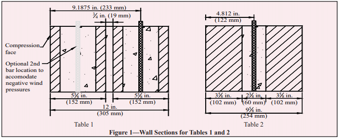
The engineer has the option of locating the structural reinforcing steel in the collar joint or in one or both wythes. While there is no direct prohibition against placing reinforcement in both the collar joint and the unit cores, practically speaking there is rarely a structural reason to complicate the cross section with this configuration.

With some units, it may be easier to install reinforcement in the collar joint, such as when both wythes are solid or lack sufficient cell space for reinforcing bars. Depending on the units selected, the collar joint may or may not provide the option to center the reinforcement within the wall cross section. For example, when the units are not the same thickness, the collar joint does not necessarily span the center of the section.

Conversely, if off-set reinforcing is preferred, perhaps to accommodate unbalanced lateral loads, it may be benefi cial to place the vertical bars in the unit cores. Placing reinforcement in the unit cores permits a thinner collar joint and possibly a thinner overall cross-section. Unit cores may provide a larger and less congested opening for the reinforcing bars and grout since the collar joint will be crossed with connecting wall ties. There is also the possibly that for a given geometry, centered reinforcement does end up in a core space.

Reinforcement can also be placed in the cells of each wythe, providing a double curtain of steel to resist lateral loads from both directions, as in the case of wind pressure and suction.

Collar Joint Width

There are no prescriptive minimums or maximums explicit to collar joint thickness in either Building Code Requirements for Masonry Structures or the International Building Code, however there are some practical limitations for constructability and also code compliance in reinforcing and grouting that effect the collar joint dimension. Many of these are covered in TEK 16-01A but a few key points from the codes that are especially relevant for reinforced composite masonry walls included below:

  • Wall tie length: Noncomposite cavity walls have a cavity thickness limit of 4½ in. (114 mm) unless a wall tie analysis is performed. There is no such limitation on width for filled collar joints in composite construction since the wall ties can be considered fully supported by the mortar or grout, thus eliminating concern about local buckling of the ties. Practically speaking, since cavity wall construction is much more prevalent, the availability of standard ties may dictate collar joint thickness maximums close to 4½ in. (114 mm).
  • Pour and lift height: Since the collar joint must be fi lled, the width of the joint infl uences the lift height. Narrow collar joints may lead to low lift or pour heights which could impact cost and construction schedule. See Table 1 in TEK 03-02A, Grouting Concrete Masonry Walls (ref. 5) for more detailed information.
  • Course or fine grout: Codes require a minimum clear distance of ¼-in. (6.3-mm) for fine grout and ½-in. (13-mm) for coarse grout between reinforcing bars and any face of the masonry unit.
  • Course or fine grout: Codes require a minimum clear distance of ¼-in. (6.3-mm) for fine grout and ½-in. (13-mm) for coarse grout between reinforcing bars and any face of the masonry unit.
  • Grout or mortar fill: Although codes permit collar joints to be filled with either mortar or grout, grout is preferred because it helps ensure complete filling of the collar joint without creating voids. Note that collar joints less than ¾ in. (19 mm), unless otherwise required, are to be filled with mortar as the wall is built. Increasing the slump of the mortar to achieve a solidly filled joint is preferred. This effectively requires a ¾-in. (19-mm) minimum on collar joints with structural reinforcing since it is also a code requirement that reinforcing bars be placed in grout, not mortar.
  • Reinforcing bar diameter: The reinforcing bar diameter cannot exceed one-half the least clear dimension of the collar joint.
  • Horizontal bond beams: Bond beams may be required to meet prescriptive code requirements such as seismic detailing. The collar joint then must be wide enough to accommodate the horizontal and vertical reinforcement along with the accompanying clearances for embedment in grout.  

Unit Selection for Each Wythe

Aesthetic criteria may play a primary role in unit selection for reinforced composite walls. Designing the composite wall to match modular dimensions may make detailing of interfaces much easier. Window and door frames, foundations, connectors and other accessories may coordinate better if typical masonry wall thicknesses are maintained. Additional criteria that influence the selection of units for reinforced composite walls include:

  • Size and number of reinforcing bars to be used and the cell space required to accommodate them.
  • Cover requirements (see ref. 6) may come into play when reinforcement is placed in the cells off-center. Cover requirements could affect unit selection, based on the desired bar placement; face shell thickness and cell dimensions.
  • If double curtains of vertical reinforcement are used, it is preferable to use units of the same thickness to produce a symmetrical cross section.

Structural Considerations

Some structural considerations were addressed earlier in this TEK during the discussion of cross section determination. Since reinforced composite masonry by definition acts as one wall to resist loads, the design procedures are virtually the same as for all reinforced masonry walls. TEK 14-07C, ASD of Concrete Masonry (2012 IBC & 2011 MSJC) (ref. 7) details design procedures. A few key points should be stressed, however:

  • Analysis: Empirical design methods are not permitted to be used for reinforced multiwythe composite masonry walls.
  • Section properties: Section properties must be calculated using the transformed section method described in TEK 1601A (ref. 3).
  • Shear stresses: Shear stress in the plane of interface between wythes and collar joint is limited to 5 psi (34.5 kPa) for mortared collar joints and 10 psi (68.9 kPa) for grouted collar joints.

DESIGN TABLES

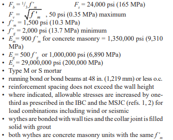
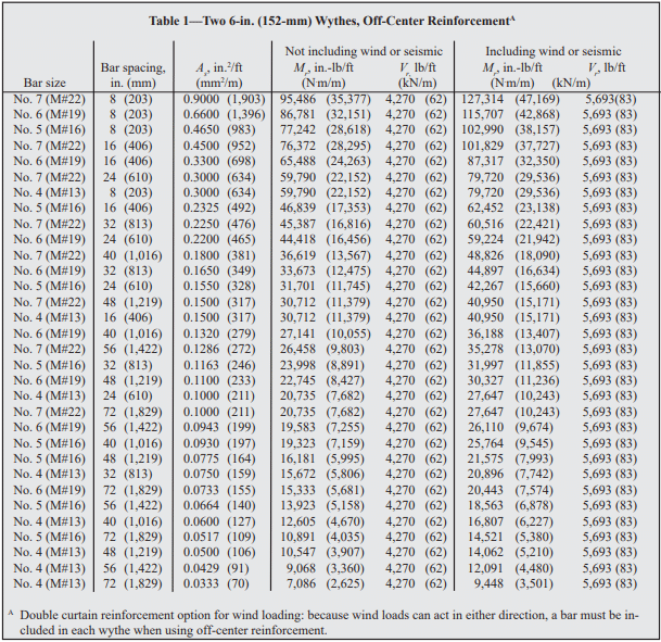
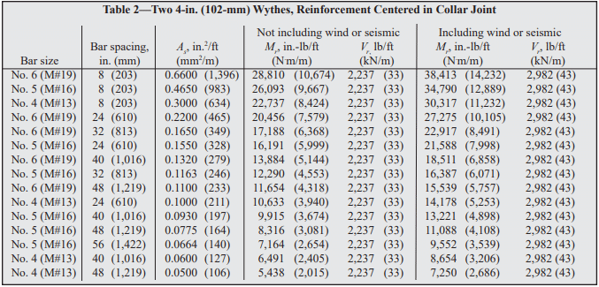
Design tables for select reinforced composite walls are included below. The tables include maximum bending moments and shear loads that can be sustained without exceeding the allowable stresses defined in the International Building Code and Building Code Requirements for Masonry Structures. These can be compared to Tables 1 and 2 of TEK 14-19B, ASD Tables for Reinforced CM Walls (2012 IBC & 2011 MSJC) (ref. 8) for wall subjected to uniform lateral loads to ensure the wall under consideration is not loaded beyond its design capacity. The examples are based on the following criteria:

The examples are based on the following criteria:

• Allowable stresses:

In addition to these tables, it is important to check all code requirements governing grout space dimensions and maximum reinforcement size to ensure that the selected reinforcing bar is not too large for the collar joint. The designer must also check shear stress at the unit/grout interface to ensure it does not exceed the code allowable stress for the design loading.

CONSTRUCTION AND DETAILING REQUIREMENTS

With composite wall construction, the two masonry wythes are not required to be built at the same time unless the collar joint is less than ¾ in. (19 mm), as the code mandates that those collar joints be mortared as the wall is built. Practically speaking it is easier to build both wythes at the same time to facilitate placing either the grout or the mortar in the collar joint at the code required pour heights.

It can be more complex to grout composite walls. Consider that a composite wall may have requirements to grout the collar joint for the full wall height and length but the cores of the concrete masonry units may only need to be partially grouted at reinforcing bar locations. Installing reinforcement and grout in the collar joint space can also be more time-consuming because of congestion due to the wall ties.

Nonmodular composite wall sections may cause diffi culty at points where they interface with modular elements such as window and door frames, bonding at corners and bonding with modular masonry walls. 

NOTATIONS

As     = effective cross-sectional area of reinforcement, in.²/ft (mm²/m)
d       = distance from extreme compression fiber to centroid of tension reinforcement, in. (mm)
Eg     = modulus of elasticity of grout, psi (MPa)
Em    = modulus of elasticity of masonry in compression, psi (MPa)
Es     = modulus of elasticity of steel, psi (MPa)
Fb     = allowable compressive stress due to flexure only, psi (MPa)
Fs     = allowable tensile or compressive stress in reinforcement, psi (MPa)
Fv     = allowable shear stress in masonry, psi (MPa)
f’g     = specified compressive strength of grout, psi (MPa)
f’m    = specified compressive strength of masonry, psi (MPa)
Mr    = resisting moment of wall, in.-lb/ft (kNm/m)
Vr     = resisting shear of wall, lb/ft (kN/m)

REFERENCES

  1. International Building Code 2003. International Code Council, 2003.
  2. Building Code Requirements for Masonry Structures, ACI 530-05/ASCE 5-05/TMS 402-05. Reported by the Masonry Standards Joint Committee, 2005.
  3. Multi-Wythe Concrete Masonry Walls, TEK 16-01A. Concrete Masonry & Hardscapes Association, 2005.
  4. Structural Design of Unreinforced Composite Masonry, TEK 16-02B, Concrete Masonry & Hardscapes Association, 2001
  5. Grouting Concrete Masonry Walls, TEK 03-02A, Concrete Masonry & Hardscapes Association, 2005.
  6. Steel Reinforcement for Concrete Masonry, TEK 12-04D, Concrete Masonry & Hardscapes Association, 2006.
  7. ASD of Concrete Masonry (2012 IBC & 2011 MSJC), TEK 14-07C, Concrete Masonry & Hardscapes Association, 2004.
  8. ASD Tables for Reinforced CM Walls (2012 IBC & 2011 MSJC), TEK 14-19B, Concrete Masonry & Hardscapes Association, 2011.
Anchors and Ties for Masonry

INTRODUCTION

Masonry connectors can be classified as wall ties, anchors or fasteners. Wall ties connect one masonry wythe to an adjacent wythe. Anchors connect masonry to a structural support or frame. Fasteners connect an appliance to masonry. This TEK covers metal wall ties and anchors. Fasteners are discussed in TEK 12-05 (ref. 1).

The design of anchors and ties is covered by the International Building Code and Building Code Requirements for Masonry Structures (refs. 2, 3).These provisions require that connectors be designed to resist applied loads and that the type, size and location of connectors be shown or indicated on project drawings. This TEK provides a guide to assist the designer in determining anchor and tie capacity in accordance with the applicable standards and building code requirements.

DESIGN CRITERIA

Connectors play a very important role in providing structural integrity and good serviceability. As a result, when selecting connectors for a project, designers should consider a number of design criteria. Connectors should:

  1. Transmit out-of-plane loads from one wythe of masonry to another or from masonry to its lateral support with a minimum amount of deformation. It is important to reduce the potential for cracking in masonry due to deflection. There is no specific criteria on connector stiffness, but some authorities suggest that a stiffness of 2,000 lb/in. (350 kN/m) is a reasonable target.
  2. Allow differential in-plane movement between two masonry wythes connected with ties. This is especially significant as more insulation is used between the outer and inner wythes of cavity walls and where wythes of dissimilar materials are anchored together. On the surface, it may appear that this criterion is in conflict with Item 1, but it simply means that connectors must be stiff in one direction (out-of-plane) and flexible in the other (in plane). Note that some connectors allow much more movement than unreinforced masonry can tolerate (see ref. 27 for a discussion of potential masonry wall movements). In order to preserve the in-plane and out-of-plane wall tie stiffness, current codes (refs. 2, 3) allow cavity widths up to 4 1/2 in. (114 mm) without performing wall tie analysis. With an engineered analysis of the wall ties, cavity widths may be significantly increased to accommodate thicker insulation.
  3. Meet applicable material requirements:
  • plate and bent-bar anchors—ASTM A36 (ref. 4)
  • sheet-metal anchors and ties—ASTM A1008 (ref. 5)
  • wire anchors and ties—ASTM A82 (ref. 6), and adjustable wire ties must also meet the requirements illustrated in Figure 1
  • wire mesh ties – ASTM A185 (ref. 7)
  1. Provide adequate corrosion protection. Where carbon steel ties and anchors are specified, corrosion protection must be provided by either galvanizing or epoxy coating in conformance with the following (ref. 8):

A. Galvanized coatings:

  • Joint reinforcement in interior walls exposed to a mean relative humidity of 75% or less—ASTM A641 (ref. 13), 0.1 oz zinc/ft2 (0.031 kg zinc/m2)
  • Joint reinforcement, wire ties and wire anchors, exterior walls or interior walls exposed to a mean relative humidity greater than 75%—ASTM A153 (ref. 14), 1.5 oz zinc/ft2 (458 g/m2)
  • Sheet metal ties or anchors, interior walls exposed to a mean relative humidity of 75% or less—ASTM A653 (ref. 15) Coating Designation G60
  • Sheet metal ties or anchors, exterior walls or interior walls exposed to a mean relative humidity greater than 75%—ASTM A153 Class B
  • Steel plates and bars, exterior walls or interior walls exposed to a mean relative humidity greater than 75%—ASTM A123 (ref. 16) or ASTM A153 Class B
  • Plate and bent-bar anchors—ASTM A480 and ASTM A666 (refs. 10, 11)
  • Sheet metal anchors and ties—ASTM A480 and ASTM A240 (refs. 10, 12)
  • Wire ties and anchors—ASTM A580

B. Epoxy coatings:

  • Joint reinforcement—ASTM A884 (ref. 17) Class A
    Type 1 > 7 mils (175 µm)
  • Wire ties and anchors—ASTM A899 (ref. 18) Class C
    20 mils (508 µm)
  • Sheet metal ties and anchors—20 mils (508 µm) per
    surface or per manufacturer’s specification
  • Where stainless steel anchors and ties are specified,
    Specification for Masonry Structures (ref. 8) requires
    that AISI Type 304 or 316 stainless steel be provided
    that complies with:
  • Joint reinforcement—ASTM A580 (ref. 9)
  1. Accommodate construction by being simple in design and easy to install. Connectors should not be so large and cumbersome as to leave insufficient room for mortar in the joints, which can result in a greater tendency to allow water migration into the wall. In the same way, connectors should readily accommodate insulation in wall cavities.

WALL TIE AND ANCHOR REQUIREMENTS

Multiwythe Masonry Wall Types

Wall ties are used in all three types of multiwythe walls (composite, noncomposite and veneer), although some requirements vary slightly depending on the application. The primary differences between these wall systems are in construction details and how the applied loads are assumed to be distributed.

Composite walls are designed so that the masonry wythes act together as a single structural member. This requires the masonry wythes to be connected by masonry headers or by a mortar- or grout filled collar joint and wall ties to help ensure adequate load transfer. TEKs 16-01A and 16-02B (refs. 19, 20) more fully describe composite walls.

In noncomposite masonry (also referred to as a cavity wall), wythes are connected with metal wall ties, but they are designed such that each wythe individually resists the loads imposed on it. Noncomposite walls are discussed in TEKs 16-01A and 16-04A (refs. 19, 21).

In a veneer wall, the backup wythe is designed as the load-resisting system, with the veneer providing the architectural wall finish. Information on veneer walls can be found in TEKs 05-01B and 03 06C (refs. 22, 23). Note that although a cavity wall is defined as a noncomposite masonry wall (ref. 3), the term cavity wall is also commonly used to describe a veneer wall with masonry backup.

Building Code Requirements for Masonry Structures also includes empirical requirements for wire wall ties and strap-type ties used to connect intersecting walls. These requirements are covered in TEK 14-08B (ref. 24).

Wall Ties

Wire wall ties can be either one piece unit ties, adjustable two piece ties, joint reinforcement or prefabricated assemblies made up of joint reinforcement and adjustable ties (see Figure 2). Note that the 2011 edition of Specification for Masonry Structures allows adjustable pintle ties to have only one leg (previously, two legs were required for this type of wall tie).

Wall ties do not have to be engineered unless the nominal width of the wall cavity is greater than 4 1/2 in. (114 mm). These wall tie analyses are becoming more common as a means to accommodate more thermal insulation in the wall cavity. Masonry cavities up to 14 in. (356 mm) have been engineered. Of note for these analyses is that the span of wire is a more critical factor than cavity width, i.e. the span length of the pintel component typically controls the mode of failure.

The prescribed size and spacing is presumed to provide connections that will be adequate for the loading conditions covered by the code. These wall tie spacing requirements can be found in TEK 03-06C (for veneers) and TEK 16-01A (for composite and noncomposite walls). Note that truss-type joint reinforcement is stiffer in the plane of a wall compared to ladder-type, so it is more restrictive of differential movement. For this reason, laddertype joint reinforcement is recommended when significant differential movement is expected between the two wythes or when vertical reinforcement is used. See TEK 12-02B (ref. 25) for more information.

Additional tests are needed for adjustable anchors of different configurations and for one piece anchors. Proprietary anchors are also available. Manufacturers of proprietary anchors should furnish test data to document comparability with industry-tested anchors.

Anchors are usually designed based on their contributory area. This is the traditional approach, but some computer models suggest that this approach does not always reflect the actual behavior of the anchorage system. However, there is currently no accepted computer program to address this point, so most designers still use the contributory area approach with a factor of safety of three. The use of additional anchors near the edges of wall panels is also recommended and required around large openings and within 12 in. (305 mm) of unsupported edges.

CONSTRUCTION

When typical ties and anchors are properly embedded in mortar or grout, mortar pullout or pushout will not usually be the controlling mode of failure. Specification for Masonry Structures requires that connectors be embedded at least 1 1/2 in. (38 mm) into a mortar bed of solid units. The required embedment of unit ties in hollow masonry is such that the tie must extend completely across the hollow units. Proper embedment can be easily attained with the use of prefabricated assemblies of joint reinforcement and unit ties. Because of the magnitude of loads on anchors, it is recommended that they be embedded in filled cores of hollow units. See TEK 03-06C for more detailed information.

REFERENCES

  1. Fasteners for Concrete Masonry, TEK 12-05. Concrete Masonry & Hardscapes Association, 2005.
  2. International Building Code. International Code Council, 2012.
  3. Building Code Requirements for Masonry Structures, TMS 402-11/ACI 530-11/ASCE 5-11. Reported by the Masonry Standards Joint Committee, 2011.
  4. Standard Specification for Carbon Structural Steel, A36-ASTM International, 2008.
  5. Standard Specification for Steel, Sheet, Cold-Rolled, Carbon, Structural, High-Strength Low-Alloy with Improved Formability, A1008-11. ASTM International, 2011.
  6. Standard Specification for Steel Wire, Plain for Concrete Reinforcement, A82-07. ASTM International, 2007.
  7. Standard Specification for Steel Welded Wire Reinforcement, Plain, for Concrete, A185-07. ASTM International, 2007.
  8. Specification for Masonry Structures, TMS 602 -11/ACI 530.1-11/ASCE 6-11. Reported by the Masonry Standards Joint Committee, 2011.
  9. Standard Specification for Stainless Steel Wire, ASTM A580-08. ASTM International, 2008.
  10. Standard Specification for General Requirements for Flat Rolled Stainless and Heat-Resisting Steel Plate, Sheet, and Strip, ASTM A480-11a. ASTM International, 2011.
  11. Standard Specification for Annealed or Cold-Worked Austenitic Stainless Steel, Sheet, Strip, Plate and Flat Bar, ASTM A666-10. ASTM International, 2010.
  12. Standard Specification for Chromium and Chromium Nickel Stainless Steel Plate, Sheet and Strip for Pressure Vessels and for General Applications, ASTM A240-11a. ASTM International, 2011.
  13. Standard Specification for Zinc-Coated (Galvanized) Carbon Steel Wire, ASTM A641-09a. ASTM International, 2009.
  14. Standard Specification for Zinc Coating (Hot-Dip) on Iron and Steel Hardware, ASTM A153-09. ASTM International, 2009.
  15. Standard Specification for Steel Sheet, Zinc-Coated Galvanized or Zinc-Iron Alloy-Coated Galvannealed by the Hot-Dip Process, ASTM A653-10. ASTM International, 2010.
  16. Standard Specification for Zinc (Hot-Dip Galvanized) Coating on Iron and Steel Products, ASTM A123-09. ASTM International, 2009.
  17. Standard Specification for Epoxy-Coated Steel Wire and Welded Wire Fabric for Reinforcement, ASTM A884-06. ASTM International, 2006.
  18. Standard Specification for Steel Wire Epoxy Coated, ASTM A899-91(2007). ASTM International, 2007.
  19. Multiwythe Concrete Masonry Walls, TEK 16-01A, Concrete Masonry & Hardscapes Association, 2005.
  20. Structural Design of Unreinforced Composite Masonry, TEK 16-02B, Concrete Masonry & Hardscapes Association, 2002.
  21. Design of Concrete Masonry Noncomposite (Cavity) Walls, TEK 16-04A, Concrete Masonry & Hardscapes Association, 2004.
  22. Concrete Masonry Veneer Details, TEK 05-01B, Concrete Masonry & Hardscapes Association, 2003.
  23. Concrete Masonry Veneers, TEK 03-06C, Concrete Masonry & Hardscapes Association, 2012.
  24. Empirical Design of Concrete Masonry Walls, TEK 14-08B, Concrete Masonry & Hardscapes Association, 2008.
  25. Joint Reinforcement for Concrete Masonry, TEK 12-02B, Concrete Masonry & Hardscapes Association, 2005.
  26. Porter, Max L., Lehr, Bradley R., Barnes, Bruce A., Attachments for Masonry Structures, Engineering Research Institute, Iowa State University, February 1992.
  27. Crack Control Strategies for Concrete Masonry Construction, CMU-TEC-009-23, Concrete Masonry & Hardscapes Association, 2023.

Insulating Conrete Masonry Walls

INTRODUCTION

The variety of concrete masonry wall constructions provides for
a number of insulating strategies, including: interior insulation,
insulated cavities, insulation inserts, foamed-in-place insulation,
granular fills in block core spaces, and exterior insulation
systems. Each masonry wall design has different advantages
and limitations with regard to each of these insulation
strategies. The choice of insulation will depend on the desired
thermal properties, climate conditions, ease of construction,
cost, and other design criteria. Note that insulation position
within the wall can impact dew point location, and hence affect
the condensation potential. See TEK 06-17B, Condensation
Control in Concrete Masonry Walls
(ref. 1) for more detailed
information. Similarly, some insulations can act as an air barrier
when installed continuously and with sealed joints. See TEK
06-14B, Control of Infiltration in Concrete Masonry Walls, (ref.
2) for further information.

MASONRY THERMAL PERFORMANCE

The thermal performance of a masonry wall depends on its steady state thermal characteristics (described by R-value or U-factor) as well as the thermal mass (heat capacity) characteristics of the wall. The steady state and mass performance are influenced by the size and type of masonry unit, type and location of insulation, finish materials, and density of masonry. Lower density concrete masonry mix designs result in higher R-values (i.e., lower U-factors) than higher density concretes. Thermal mass describes the ability of materials to store heat. Because of its comparatively high density and specific heat, masonry provides very effective thermal storage. Masonry walls remain warm or cool long after the heat or airconditioning has shut off. This, in turn, effectively reduces heating and cooling loads, moderates indoor temperature swings, and shifts heating and cooling loads to off-peak hours. Due to the significant benefits of concrete masonry’s inherent thermal mass, concrete masonry buildings can provide similar performance to more heavily insulated frame buildings.

The benefits of thermal mass have been incorporated into energy code requirements as well as sophisticated computer models. Energy codes and standards such as the International Energy Conservation Code (IECC) (ref. 5) and Energy Efficient Standard for Buildings Except Low-Rise Residential Buildings, ASHRAE/IESNA Standard 90.1 (ref. 6), permit concrete masonry walls to have less insulation than frame wall systems to meet the energy requirements.

Although the thermal mass and inherent R-value/U-factor of concrete masonry may be enough to meet energy code requirements (particularly in warmer climates), concrete masonry walls often require additional insulation. When they do, there are many options available for insulating concrete masonry construction. When required, concrete masonry can provide walls with R-values that exceed code minimums (see refs. 3, 4). For overall project economy, however, the industry suggests a parametric analysis to determine reasonable insulation levels for the building envelope elements.

The effectiveness of thermal mass varies with factors such as climate, building design and insulation position. The effects of insulation position are discussed in the following sections. Note, however, that depending on the specific code compliance method chosen, insulation position may not be reflected in a particular code or standard.

There are several methods available to comply with the energy requirements of the IECC. One of the options, the IECC prescriptive R-values (IECC Table 502.2(1)) calls for “continuous insulation” on concrete masonry and other mass walls. This refers to insulation uninterrupted by furring or by the webs of concrete masonry units. Examples include rigid insulation adhered to the interior of the wall with furring and drywall applied over the insulation, continuous insulation in a masonry cavity wall, and exterior insulation and finish systems. If the concrete masonry wall will not include continuous insulation, there are several other options to comply with the IECC requirements—concrete masonry walls are not required to have continuous insulation in order to meet the IECC. See TEK 06-12E, Concrete Masonry in the 2012 Edition of the IECC and TEK 06-04B, Energy Code Compliance Using COMcheck (refs. 7, 8).

INTERIOR INSULATION

Interior insulation refers to insulation applied to the interior side of the concrete masonry, as shown in Figure 1. The insulation may be rigid board (extruded or expanded polystyrene or polyisocyanurate), closed-cell spray polyurethane foam, cellular glass, fibrous batt, or fibrous blown-in insulation (note, however, that fibrous insulation is susceptible to moisture). The interior wall surface is usually finished with gypsum wallboard or paneling.

Interior insulation allows for exposed masonry on the exterior, but isolates the masonry from the building’s interior and so may reduce the effects of thermal mass.

With rigid board insulation, an adhesive is used to temporarily hold the insulation in place while mechanical fasteners and a protective finish are applied. Furring may be used and held away from the face of the masonry with spacers. The space created by the spacers provides moisture protection, as well as a convenient and economical location for additional insulation, wiring or pipes.

As an alternative, wood or metal furring can be installed with insulation placed between the furring. The furring size is determined by the type of insulation and R-value required. Because the furring penetrates the insulation, the furring properties must be considered in analyzing the wall’s thermal performance. Steel penetrations through insulation significantly affect the thermal resistance by conducting heat from one side of the insulation to the other. Although not as conductive as metal, the thermal resistance of wood and the cross sectional area of the wood furring penetration should be taken into account when determining overall R-values. See TEK 06-13B, Thermal Bridges in Wall Construction (ref. 9) for more information.

Closed cell spray polyurethane foam is typically installed between interior furring. The foam is applied as a liquid and expands in-place. Proper training helps ensure a quality installation. The foam is resistant to both air and water vapor transmission.

When using interior insulation, concrete masonry can accommodate both vertical and horizontal reinforcement with partial or full grouting without interrupting the insulation layer. The durability, weather resistance, and impact resistance of the exterior of a wall remain unchanged with the addition of interior insulation. Impact resistance on the interior surface is determined by the interior finish.

INTEGRAL INSULATION

Figure 2 illustrates some typical integral insulations in single-wythe masonry walls. Integral insulation refers to insulation placed between two layers of thermal mass. Examples include insulation placed in concrete masonry cores and continuous insulation in a masonry cavity wall (note that an insulated masonry cavity wall can also be considered as exterior insulation if the thermal mass effect of the veneer is disregarded).

With integral insulation, some of the thermal mass (masonry) is directly in contact with the indoor air, which provides excellent thermal mass benefits, while allowing exposed masonry on both the exterior and interior.

Multi-wythe cavity walls contain insulation between two wythes of masonry. The continuous cavity insulation minimizes thermal bridging. The cavity width can be varied to achieve a wide range of R-values. Cavity insulation can be rigid board, closed cell spray polyurethane foam, or loose fill. To further increase the thermal performance, the cores of the backup wythe may be insulated.

When rigid board insulation is used in the cavity, the inner masonry wythe is typically completed first. The insulation is precut or scored by the manufacturer to facilitate placement between the wall ties. The board insulation may be attached with an adhesive or mechanical fasteners. Tight joints between the insulation boards maximize the thermal performance and reduce air leakage. In some cases, the joints between boards are set into an expandable bead of sealant, or caulked or taped to act as an air barrier.

Integral insulations placed in masonry cores are typically molded polystyrene inserts, foams, or expanded perlite or vermiculite granular fills. As for the furring used for interior insulation, the thermal resistance of the concrete masonry webs and any grouted cores should be accounted for when determining the thermal performance of the wall (see TEK 06-02C, ref. 3, for tabulated R-values of walls with core insulation). When using core insulation, the insulation should occupy all ungrouted core spaces (although some rigid inserts are configured to accommodate reinforcing steel and grout in the same cell).

Foamed-in-place insulation is installed in masonry cores after the wall is completed. The installer either fills the cores from the top of the wall or pumps the foam through small holes drilled into the masonry. Foams may be sensitive to temperature, mixing conditions, or other factors. Therefore, manufacturers’ instructions should be carefully followed to avoid excessive shrinkage due to improper mixing or placing of the foam.

Polystyrene inserts may be placed in the cores of conventional masonry units or used in specially designed units. Inserts are available in many shapes and sizes to provide a range of R-values and accommodate various construction conditions. In pre-insulated masonry, the inserts are installed by the manufacturer. Inserts are also available which are installed at the construction site.

Specially designed concrete masonry units may incorporate reduced height webs to accommodate inserts in the cores. Such webs also reduce thermal bridging through masonry, since the reduced web area provides a smaller cross-sectional area for heat flow through a wall. To further reduce thermal bridging, some manufacturers have developed concrete masonry units with two cross webs rather than three.

Vertical and horizontal reinforcement grouted into the concrete masonry cores may be required for structural performance. Cores to be grouted are isolated from cores to be insulated by placing mortar on the webs to confine the grout. Granular or foam insulation is placed in the ungrouted cores within the wall. Thermal resistance is then determined based on the average R-value of the wall area (see TEK 06-02C, ref. 3, for an explanation and example calculation). Some rigid inserts are configured to accommodate reinforcing steel and grout, to provide both thermal protection and structural performance. When inserts are used in grouted construction, the coderequired minimum grout space dimensions must be met (see TEK 03-02A, ref. 10).

Granular fills are placed in masonry cores as the wall is laid up. Usually, the fills are poured directly from bags into the cores. A small amount of settlement usually occurs, but has a relatively small effect on overall performance. Granular fills tend to flow out of any holes in the wall system. Therefore, weep holes should have noncorrosive screens on the interior or wicks to contain the fill while allowing water drainage. Bee holes or other gaps in the mortar joints should be filled. In addition, drilled-in anchors placed after the insulation require special installation procedures to prevent loss of the granular fill.

EXTERIOR INSULATION

Exterior insulated masonry walls are walls that have insulation on the exterior side of the thermal mass. In these walls, continuous exterior insulation envelopes the masonry, minimizing the effect of thermal bridges. This places the thermal mass inside the insulation layer. Exterior insulation keeps masonry directly in contact with the interior conditioned air, providing the most thermal mass benefit of the three insulation strategies.

Exterior insulation also reduces heat loss and moisture movement due to air leakage when joints between the insulation boards are sealed. Exterior insulation negates the aesthetic advantage of exposed masonry. In addition, the insulation requires a protective finish to maintain the durability, integrity, and effectiveness of the insulation.

For exterior stucco installation, a reinforcing mesh is applied to reinforce the finish coating, improving the crack and impact resistance. Fiberglass mesh, corrosion-resistant woven wire mesh or metal lath is used for this purpose. After the mesh is installed, mechanical fasteners are placed through the insulation, to anchor securely into the concrete masonry. Mechanical fasteners can be either metal or nylon, although nylon limits the heat loss through the fasteners.

After the insulation and reinforcing mesh are mechanically fastened to the masonry, a finish coating is troweled onto the surface. This surface gives the wall its final color and texture, as well as providing weather and impact resistance.

BELOW GRADE APPLICATIONS

Below grade masonry walls typically use single-wythe wall construction, which can accommodate interior, integral, or exterior insulation.

Exterior or integral insulation is effective in moderating interior temperatures and in shifting peak energy loads. The typical furring used for interior insulation provides a place to run electric and plumbing lines, as well as being convenient for installing drywall or other interior finishes.

When using exterior or integral insulation strategies, architectural concrete masonry units provide a finished surface on the interior. Using smooth molded units at the wall base facilitates screeding the slab. After casting the slab, a molding strip, also serving as an electric raceway, can be placed against the smooth first course. The remainder of the wall may be constructed of smooth, split-face, split ribbed, ground faced, scored or other architectural concrete masonry units.

Insulation on the exterior of below grade portions of the wall is temporarily held in place by adhesives until the backfill is placed. That portion of the rigid board which extends above grade should be mechanically attached and protected.

REFERENCES

  1. Condensation Control in Concrete Masonry Walls, TEK 06-17B, Concrete Masonry & Hardscapes Association, 2011.
  2. Control of Infiltration in Concrete Masonry Walls, TEK 06-14A, Concrete Masonry & Hardscapes Association, 2011.
  3. R-Values and U-Factors of Single Wythe Concrete Masonry Walls, TEK 06-02C, Concrete Masonry & Hardscapes Association, 2013.
  4. R-Values of Multi-Wythe Concrete Masonry Walls, TEK 06-01C, Concrete Masonry & Hardscapes Association, 2013.
  5. International Energy Conservation Code. International Code Council, 2003, 2006 and 2009.
  6. Energy Efficient Standard for Buildings Except LowRise Residential Buildings, ASHRAE/IESNA Standard 90.1. American Society of Heating, Refrigerating and Air Conditioning Engineers and Illuminating Engineers Society, 2001, 2004 and 2007.
  7. International Energy Conservation Code and Concrete Masonry, TEK 6-12C. Concrete Masonry & Hardscapes Association, 2007.
  8. Energy Code Compliance Using COMcheck TEK 06-04B, Concrete Masonry & Hardscapes Association, 2012.
  9. Thermal Bridges in Wall Construction, TEK 06-13B, Concrete Masonry & Hardscapes Association, 2010.
  10. Grouting Concrete Masonry Walls, TEK 03-02A, Concrete Masonry & Hardscapes Association, 2005.