Allowable Stress Design of Pier and Panel Highway Sound Barrier Walls
INTRODUCTION
Sound barrier walls are increasingly being used to reduce the impact of traffic noise on properties abutting major urban traffic routes. Because concrete masonry possesses many desirable features and properties—excellent sound resistance, low cost, design flexibility, structural capability and durability, it is an excellent material for the design and construction of highway sound barrier walls.
Aesthetics is also an important consideration. Noise barriers significantly impact a highway’s visual impression. Visual qualities of noise barriers include overall shape, end conditions, color, texture, plantings and artistic treatment.
The variety of concrete masonry surface textures, colors and patterns has led to its extensive use in sound barrier walls.
Various types of concrete masonry walls may be used for sound barriers. Pier and panel walls are relatively easy to build and are economical due to the reduced thickness of the walls and the intermittent pier foundations. In addition, the piers can be offset with respect to the panels to achieve desired aesthetic effects. Pier and panel walls are also easily adapted to varying terrain conditions and are often used in areas that have expansive soils.
This TEK presents information on the structural design of concrete masonry pier and panel sound barrier walls. Requirements and considerations for reduction of highway traffic noise are discussed in TEK 13-03A, Concrete Masonry Highway Noise Barriers (ref. 2).
DESIGN
Building Code Requirements for Masonry Structures, ACI 530/ASCE 5/TMS 402 (ref. 1) includes requirements for allowable stress design, strength design and prestressed approaches. The allowable stress design approach was used to develop the designs in this TEK. Allowable stresses were increased by one-third, as permitted for load combinations which include wind or seismic loads. Allowable Stress Design of Concrete Masonry, TEK 14-07C (ref. 4), describes the basic design approach.
Materials and Workmanship
Since concrete masonry sound barrier walls are subject to a wide range of load conditions, temperatures and moisture conditions, the selection of proper materials and proper workmanship is very important to ensure durability and satisfactory structural performance. Accordingly, it is recommended that materials (concrete masonry units, mortar, grout and reinforcement) comply with applicable requirements contained in Building Code Requirements for Masonry Structures (ref. 1).
Lateral Loads
Design lateral loads should be in accordance with those specified by local or state building and highway departments. If design lateral loads are not specified, it is recommended that they conform to those specified in Minimum Design Loads for Buildings and Other Structures, ASCE 7 (ref. 3). Wind and earthquake loads required in this standard are briefly described in the following paragraphs.
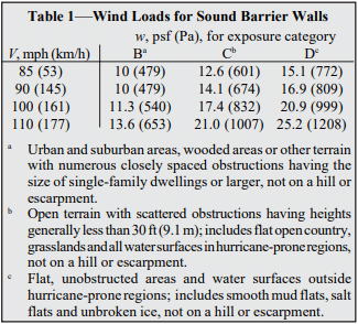
Design wind loads (F) on sound barrier walls may be determined as follows:

For the wall designs in this TEK, G is taken as 0.85 and C as 1.2. The minimum wind load specified in ASCE 7 is f 10 psf (479 Pa). For basic wind speeds of 85 mph (minimum), 90 mph, 100 mph, and 110 mph (53, 145, 161, and 177 kmph), the corresponding wind loads are listed in Table 1.
Earthquake loads (F ) on sound barrier walls may be p determined as follows, considering the wall system as a reinforced masonry non-building structure (ref. 3):

Seismic loads for a range of conditions are listed in Table 3.


Deflections
Deflection considerations typically govern wall design for long spans and taller walls with greater lateral loads. Deflections are imposed to limit the development of vertical flexure cracks within the wall panel and horizontal flexure cracks near the base of the pier. The design information presented in this TEK is based on a maximum allowable deflection of L/240, where L is the wall span between piers.
DESIGN TABLES
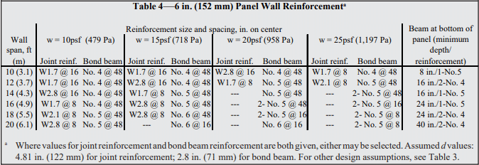
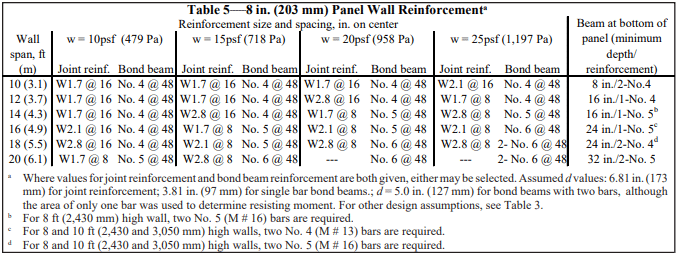
Design information for pier and panel walls is presented in Tables 4 through 7. Tables 4 and 5 provide horizontal reinforcing steel requirements for 6 in. and 8 in. (152 and 203 mm) panels, respectively. Horizontal reinforcement requirements can be met using either joint reinforcement or bond beams with reinforcing bars.
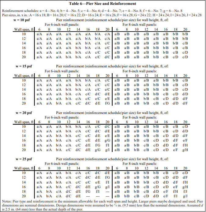
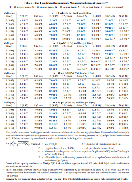
Table 6 provides pier size and reinforcement requirements for various lateral loads. Table 7 lists minimum sizes for pier foundations, as well as minimum embedment depths. These components of pier and panel walls are illustrated in Figure 1.
When pier and panels are used, walls are considered as deep beams, spanning horizontally between piers. Walls support their own weight, vertically, and also must resist lateral out-of-plane wind or seismic loads. The panels are built to be independent of the piers to accommodate masonry unit shrinkage and soil movement. For this design condition, wall reinforcement is located either in the horizontal bed joints or in bond beams. Wall reinforcement is based on maximum moments (M) and shears (V) in the wall panels, determined as follows:

The wall panels themselves are analyzed as simply supported beams, spanning from pier to pier.
In addition to the horizontal reinforcement, which transfers lateral loads to the piers, vertical reinforcement in the panels is required in Seismic Design Categories (SDC) C, D, E and F. Building Code Requirements for Masonry Structures (ref. 1) includes minimum prescriptive reinforcement as follows. In SDC C, vertical No. 4 (M #13) bars are located within 8 in. (203 mm) of the wall ends, and at 10 ft (3.0 m) on center along the length of the wall; minimum horizontal reinforcement requirements are satisfied by the primary reinforcement listed in Tables 4 and 5. In SDC D, E and F, vertical No. 4 (M #13) bars are located within 8 in. (203 mm) of the wall ends, and at 4 ft (1.22 m) on center along the length of the wall.
Table 6 shows pier size and vertical reinforcement requirements. Piers are designed as vertical cantilevers, not bonded with the walls, and pier reinforcement is based on maximum moment and shear, determined as follows:

Design assumptions for the pier and panel walls are given in Table 2. Note that allowable stresses were increased by one-third, as permitted for load combinations which include wind or seismic loads (ref. 1).
Requirements for concrete foundations supporting the concrete masonry piers are given in Table 7. These foundations can be constructed economically by drilling. The concrete foundation piers should contain vertical reinforcement (same as shown in Table 6) which should be properly lapped with vertical reinforcement in the concrete masonry piers. The embedment depths given in Table 7 are based on an allowable lateral passive soil pressure of 300 psf (14.4 kPa).
DESIGN EXAMPLE
A pier and panel highway sound barrier is to be designed using the following parameters:
- 6 in. (152 mm) panel thickness
- 10 ft (3.05 m) wall height
- 14 ft (4.27 m) wall span
- open terrain, stiff soil
- basic wind speed is 90 mph (145 km/h)
- SS = 0.25, SDC B
From Table 1, the design wind load is 14.1 psf (674 Pa) for a basic wind speed of 90 mph (145 km/h) and exposure C. Using Table 3, the design seismic load is determined to be 2.8 psf (0.13 kPa) for a 6 in. (152 mm) wall grouted at 48 in. (1219 mm), or less, on center, for SS = 0.25. Since the wind load is s greater, the wall will be designed for 14.1 psf (674 Pa).
Using Table 4, minimum horizontal panel reinforcement is either W1.7 (MW 11) joint reinforcement at 8 in. (203 mm) on center, or bond beams at 48 in. (1220 mm) on center reinforced with one No. 5 (M #16) bar. At the bottom, the panel requires a beam 16 in. (406 mm), or two courses, deep reinforced with one No. 5 (M # 16) bar (last column of Table 4). Because the wall is located in SDC B, vertical reinforcement is not required to meet prescriptive seismic requirements.
The minimum pier size is 16 x 18 in. (406 x 460 mm), reinforced with four No. 4 (M #13) bars, per Table 6. The pier foundation diameter is 18 in. (457 mm), and should be embedded at least 7.5 ft (2.29 m), per Table 7.
NOTATIONS
Af = area normal to wind direction, ft² (m²)
Cf = force coefficient (see ref. 3)
d = distance from extreme compression fiber to centroid of tension reinforcement, in. (mm)
Em = modulus of elasticity of masonry in compression, psi (MPa)
Es = modulus of elasticity of steel, psi (MPa)
F = design wind load, psf (Pa) (see ref. 3)
Fa = acceleration-based site factor (at 0.3 second period) (see ref. 3)
Fm = allowable masonry flexural compression stress, psi (Pa)
Fp = seismic force, psf (Pa) (see ref. 3)
Fs = allowable tensile or compressive stress in reinforcement, psi (MPa)
Fv = allowable shear stress in masonry, psi (MPa)
f’m = specified compressive strength of masonry, psi (MPa)
G = gust effect factor (see ref. 3)
H = wall height, ft (m)
I = importance factor (see ref. 3)
Ip = component importance factor (assume equal to 1.0 for sound barrier walls) (see ref. 3)
Kd = wind directionality factor (see ref. 3)
Kz = velocity pressure exposure coefficient (see ref. 3)
Kzt = hill and escarpment factor (see ref. 3)
L = wall span, ft (m)
M = maximum moment at the section under consideration, in.-lb (N-mm)
n = ratio of elastic moduli, Es/Em
P = applied lateral force, lb (N)
qz = velocity pressure, psf (Pa) (see ref. 3)
= 0.00256K KzKztKdv²I
R = response modification coefficient (see ref. 3)
Rp = component response modification factor (equal to 3.0 for reinforced masonry non-building structures) (see ref. 3)
SDS = design short period spectral acceleration =⅔(FaSS), where SS varies from less than 0.25 to greater than 1.25, and Fa is dependent on SS and soil conditions at the site (see ref. 3)
Ss = mapped maximum considered earthquake spectral response acceleration at short periods (see ref. 3)
V = shear force, lb (N)
v = basic wind speed, mph (km/h) (see ref. 3)
Wp = weight of wall, psf (Pa)
w = wind or seismic load, psf (Pa)
REFERENCES
- Building Code Requirements for Masonry Structures, ACI 530-02/ASCE 5-02/TMS 402-02. Reported by the Masonry Standards Joint Committee, 2002.
- Concrete Masonry Highway Noise Barriers, TEK 13-03A. Concrete Masonry & Hardscapes Association, 1999.
- Minimum Design Loads for Buildings and Other Structures, ASCE 7-02. American Society of Civil Engineers, 2002.
- Allowable Stress Design of Concrete Masonry, TEK 14-07C Concrete Masonry & Hardscapes Association, 2002.


