Creep Properties of Post-Tensioned and High-Rise Concrete Masonry
INTRODUCTION
Time dependent deformations such as creep are generally only designed for in prestressed (post-tensioned) concrete masonry and high-rise loadbearing masonry buildings. Ordinary concrete masonry units with grout-filled cores and steel reinforcement and designs based on well known engineering principles have been used extensively in loadbearing concrete masonry up to 20 stories in height without analysis for creep. However, as concrete masonry is used for increasingly large and tall buildings, consideration of the time-dependent deformations that occur becomes more important.
Creep is proportional to masonry dimensions and applied stress and therefore increases as height and loads increase. Prestressing (post-tensioning) of concrete masonry is another relatively new innovation where the creep properties must be taken into consideration. This procedure involves the introduction compressive forces into the masonry using prestressing tendons in order to place the masonry into a compressive mode where it is most effective.
Due to the relatively recent advent of these specialized construction procedures, creep properties of masonry have been actively studied only in the last 25 years. Much of the information prior to this was based on the documented properties of concrete. Although the properties of the two are similar, concrete masonry is composed of hollow, cementitious units that are substantially cured at the time of placement and mortar which is plastic at the time of placement. This makes the time-dependent properties somewhat different from concrete.
The majority of the effects of creep occur within the first three to five years (ref. 9). The effects are most dramatic within the first 30 days and about 90% complete at the end of the first year. The effect of these deformations on concrete masonry if they are not designed for is the potential for undesirable cracking.
TOTAL TIME-DEPENDENT DEFORMATIONS
Creep and shrinkage are deformations that occur over time and must be addressed in these specialized construction processes. There are two forms of shrinkage. 1). Drying shrinkage refers to the shrinkage that occurs as the moisture content of the masonry assemblage decreases over time. 2). Carbonation shrinkage is the reaction between the cementitious materials in the masonry and carbon dioxide in the atmosphere. Shrinkage properties are discussed extensively in CMHA’s CMU-TEC-009-23 Crack Control Strategies for Concrete Masonry Construction (ref. 4).
In research, creep is determined by measuring the total deformation on a loaded specimen and the shrinkage effects on a companion “control” specimen not subjected to loading. The creep then is determined by taking the difference in the two values.
One of the first of these studies was conducted in 1976 sponsored by the Portland Cement Association laboratories and the Concrete Masonry & Hardscapes Association to ascertain the technical and economical feasibility of constructing reinforced concrete masonry buildings as high as 50 stories (ref. 7). The research was to determine the engineering properties of the very high strength materials that would be required under the heavy sustained loading. Since that time a number of other studies have been conducted, particularly in regard to prestressed masonry construction (ref. 1, 2, 6, 7, 9, 10, 12).
CREEP
Creep refers to the increase in strain over time that occurs under sustained constant load. The deformations due to creep are normally three to five times the amount of the initial strain for concrete masonry most of which occurs within 1 year of constant stress (ref. 5). Mortar has a higher proportionate amount of creep than concrete masonry units. Even though mortar joints make up only about 7% of the area of a wall, they typically account for about 20% of the creep (ref. 10). The final creep value of masonry increases with increasing proportion of mortar.
Creep of concrete masonry is influenced by several factors:
- Unit Strength – Creep is reduced when higher strength units are used (ref. 10).
- Type of Mortar – Creep is reduced when higher strength mortar is used (ref 10).
- Percentage of Reinforcement – The presence of reinforcement reduces creep as it helps to carry some of the vertical load (ref. 2).
- Relative Humidity – The effect of relative humidity is slight on creep, however, creep tends to increase with an increase moisture content (ref. 1).
- Level of Stress – Creep of concrete masonry is proportional to stress (ref. 1 5, 7, 10).
- Age at loading – Research indicates that creep is reduced for masonry subjected to stress after 14 days of age (ref. 1, 2, 5, 7, 9). Schubert proposes that “the influence of the age at loading is slight from a masonry age of about 2 weeks onwards, as there is only a slight increase in the strength of both units and mortar after this time” (ref. 9).
- Pore Structure – An increase in pore structure of unit and mortar tends to increase creep (ref. 10).
- Aggregate Type – Little difference was found in the amount of creep between lightweight and normal weight aggregate (ref. 1, 7) and in some cases lightweight exhibited less creep (ref. 1). However, the total deformation of lightweight concrete masonry typically is greater due to the higher initial deformation.
More recent research on more conventionally strengthed concrete masonry ( f’m of 1500 psi) (10.34 MPa) produced values of creep somewhat higher (ref. 1, 10). Based on his research, Badger (ref. 1) recommends a value of 13 x 10-7 per psi (1.87 x 10⁻⁴ per MPa) for concrete masonry. The average tested prism strength was 2080 psi (14.34 MPa) for the normal weight prisms and 1580 psi (10.89 MPa) for the lightweight. Sustained stress levels of 0, 50, 150, and 250 psi (0, 0.34, 1.03, and 1.72 MPa) were applied for a period of 300 days. Test results are as shown in Figures 2 through 5. The negative creep indicated for the first 100 days in Figures 4 & 5 is not really happening. It is an aberration attributed to the more rapid drying shrinkage of the control specimens due to open cores at the top whereas the loaded specimens were covered by the loading plate. This allowed the control specimens to dry out from the inside as well as the outside as opposed to the loaded specimens which dried from the outside only.
Schultz and Scolforo (ref. 10) recommend a creep coefficient of 2.5 for Type M mortar and 4 for Type N mortar based their research. As indicated earlier, this is the ratio of creep to the amount of initial strain. The corresponding specific creep coefficient is obtained by simply dividing the creep coefficient by the modulus of elasticity. For 1500 f’m and a creep coefficient of 2.5, the specific creep coefficient kc then becomes 18.5 x 10⁻⁷ per psi (2.68 x 10⁻⁵ per MPa). A 2500 f’m with Type M mortar results in a kc of 11.1 x 10⁻⁷ per psi (16.1 x 10⁻⁵ per MPa). Since the modulus of elasticity is a function of the specified masonry strength f’m, this approach makes creep dependent on both mortar strength and masonry strength.


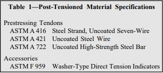
Prestressed Concrete Masonry
Creep is of particular importance in prestressed concrete masonry where it contributes to prestress losses. Prestressed concrete masonry typically involves the application of compressive stresses by a prestressing tendon to a masonry wall prior to application of the building loads. This compressive stress counteracts the applied tensile stress and increases shear capacity, providing an economical alternative to traditional reinforcement. Creep loss in prestressed masonry occurs when the prestressing tendon shortens with the masonry (ref. 1) and must be accounted for in the design. This differs from mild reinforcement which helps to minimize creep by carrying some of the load as opposed to prestressing which adds to the load carried by the masonry. Consequently creep associated with prestressed masonry is typically higher than that of reinforced masonry.
Fairly accurate estimates of creep in prestressed masonry are needed as overestimating the creep may contribute to overstressing the wall in compression when it is fully loaded. Underestimating creep can result in the wall having less available capacity than assumed which can lead to tensile cracking. Historically, in practice for concrete masonry it has been found that the sum of individual component losses determined by approved methods average between 30 to 35% of the total prestress force. This is often used as a check to ensure that all of the prestress losses are accurately accounted for.
CONCLUSIONS
Creep generally only needs to be considered in loadbearing concrete masonry high-rise buildings or in prestressed masonry construction to determine the prestress losses. Factors to consider to minimize the amount and rate of creep are as follows:
- Allow units to dry for a period (at least 14 days) after manufacture and before placing to limit creep and initial deformation due to drying shrinkage.
- Prior to the application of super-imposed loads, cure completed concrete masonry by fogging or other acceptable means to reduce the rate and amount of creep when possible.
- Increasing the amount of vertical mild reinforcement tends to decrease creep.
- Creep is reduced when higher strength units and mortar are used.
- Creep is more pronounced within the first 14 days of placement of masonry.
- Research indicates that creep in lightweight and normal weight concrete masonry are about the same.
- In high-rise buildings, the absolute shortening of the walls should not be critical, provided that all members are shortening about the same amount. This can be achieved by using walls containing similar percentages of reinforcing steel and by ensuring that all walls are subjected to similar stresses. The effects of differential shortening on continuous floor slabs can be minimized by using long spans (ref 7).
REFERENCES
- Badger, C. C.R., “Creep of Prestressed Concrete Masonry”. Thesis submitted to Department of Civil Engineering at The University of Wyoming, August 1997.
- Ben-Omran, H., Glanville, J. I., and Hatzinikolas, M. A., “Effects of Time-Dependent Deformations on the Behavior of Reinforced Masonry Columns”, TMS Journal, February 1994.
- Building Code Requirements for Masonry Structures, ACI 530-99 / ASCE 5-99 / TMS 402-99. Reported by the Masonry Standards Joint Committee, 1999.
- Crack Control Strategies for Concrete Masonry Construction, CMU-TEC-009-23, Concrete Masonry & Hardscapes Association, 2023..
- Drysdale, R. G., Hamid, A. A., and Baker, L. R., Masonry Structures: Behavior and Design. Prentice Hall, Inc., 1999.
- Forth, J. P., Bingel, P.R., and Brooks, J. J., “Influence of Age at Loading on Long-Term Movements of Clay Brick and Concrete Block Masonry”, Proceedings, Seventh North American Masonry Conference, June 1996.
- Helgason, T. and Russell, H. G., High Strength Reinforced Concrete Masonry Walls. Portland Cement Association, May 1976.
- Post-Tensioned Concrete Masonry Wall Design, TEK 1420A, Concrete Masonry & Hardscapes Association, 2002.
- Schubert, P., “Strength and Deformation Properties of Masonry Made From Lightweight Concrete Units”, Proceedings, Sixth Canadian Symposium, June 1992.
- Schultz, A. E. and Scolforo, M. J., “Engineering Design Provisions for Prestressed Masonry Part 2: Steel Stresses and Other Considerations”, TMS Journal, February, 1992.
- Van der Pluijm, R. and Vermeltfoort, A., “Influence of the Type of Mortar Joint on the Time Dependent Behaviour of Masonry”, Proceedings, Eighth Canadian Masonry Symposium, May, 1998.