Segmental retaining walls (SRWs) are gravity retaining walls which can be classified as either: conventional (structures that resist external destabilizing forces due to retained soils solely through the self-weight and batter of the SRW units); or geosynthetic reinforced soil SRWs (composite systems consisting of SRW units in combination with a mass of reinforced soil stabilized by horizontal layers of geosynthetic reinforcement materials). Both types of SRWs use dry-stacked segmental units that are typically constructed in a running bond configuration. The majority of available SRW units are dry-cast machine-produced concrete.
Conventional SRWs are classified as either single depth or multiple depth. The maximum wall height that can be constructed using a single depth unit is directly proportional to its weight, width, unit-to-unit shear strength and batter for any given soil and site geometry conditions. The maximum height can be increased by implementing a conventional crib wall approach, using multiple depths of units to increase the weight and width of the wall.
Reinforced soil SRWs utilize geosynthetic reinforcement to enlarge the effective width and weight of the gravity mass. Geosynthetic reinforcement materials are high tensile strength polymeric sheet materials. Geosynthetic reinforcement products may be geogrids or geotextiles, although most SRW construction has used geogrids. The geosynthetic reinforcement extends through the interface between the SRW units and into the soil to create a composite gravity mass structure. This enlarged composite gravity wall system, comprised of the SRW units and the reinforced soil mass, can provide the required resistance to external forces associated with taller walls, surcharged structures or more difficult soil conditions.
Segmental retaining walls afford many advantages, including design flexibility, aesthetics, economics, ease of installation, structural performance and durability. To function as planned, SRWs must be properly designed and installed. Inspection is one means of verifying that the project is constructed as designed using the specified materials.
This Tech Note is intended to provide minimum levels of design and construction inspection for segmental retaining walls. The inspection parameters follow the Design Manual for Segmental Retaining Walls (ref. 1) design methodology. This information does not replace proper design practice, but rather is intended to provide a basic outline for field use by installers, designers and inspectors.
INSPECTION
Many masonry projects of substantial size require a quality assurance program, which includes the owner’s or designer’s efforts to require a specified level of quality and to determine the acceptability of the final construction. As part of a quality assurance program, inspection includes the actions taken to ensure that the established quality assurance program is met. As a counterpart to inspection, quality control includes the contractor’s or manufacturer’s efforts to ensure that a product’s properties achieve a specified requirement. Together, inspection and quality control comprise the bulk of the procedural requirements of a typical quality assurance program.
SRW UNIT PROPERTIES
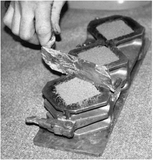
SRW units comply with the requirements of ASTM C1372, Standard Specification for Dry-Cast Segmental Retaining Wall Units (ref. 2), which governs dimensional tolerances, finish and appearance, compressive strength, absorption, and, where applicable, freeze-thaw durability. These requirements are briefly summarized below. A more thorough discussion is included in SRW-TEC-001-15, Segmental Retaining Wall Units (ref. 3). The user should refer to the most recent edition of ASTM C1372 to ensure full compliance with the standard.
Dimensional tolerances: ±1/8 in. (3.2 mm) from the specified standard overall dimensions for width, height and length (waived for architectural surfaces).
Finish and appearance:
free of cracks or other defects that interfere with proper placement or significantly impair the strength or permanence of the construction (minor chipping excepted),
when used in exposed construction, the exposed face or faces are required to not show chips, cracks or other imperfections when viewed from at least 20 ft (6.1 m) under diffused lighting,
5% of a shipment may contain chips 1 in. (25.4 mm) or smaller, or cracks less than 0.02 in. (0.5 mm) wide and not longer than 25% of the nominal unit height,
the finished exposed surface is required to conform to an approved sample of at least four units, representing the range of texture and color permitted
Minimum net area compressive strength: 3,000 psi (20.7 MPa) for an average of three units with a minimum of 2,500 psi (17.2 MPa) for an individual unit. When higher compressive strengths are specified, the tested average net area compressive strength of three units is required to equal or exceed the specified compressive strength, and the minimum required single unit strength is:
the specified compressive strength minus 500 psi (3.4 MPa) for specified compressive strengths less than 5,000 psi (34.4 MPa), or
90% of the specified compressive strength when the specified compressive strength is 5,000 psi (34.4 MPa) or greater.
Maximum water absorption:
18 lb/ft3 (288 kg/m3) for lightweight units (< 105 pcf (1,680 kg/m3))
15 lb/ft3 (240 kg/m3) for medium weight units (105 to less than 125 pcf (1,680 to 2,000 kg/m3))
13 lb/ft3 (208 kg/m3) for normal weight units ( > 125 pcf (2,000 kg/m3 or more))
Freeze-thaw durability—In areas where repeated freezing and thawing under saturated conditions occur, freeze- thaw durability is required to be demonstrated by test or by proven field performance. When testing is required, the units are required to meet the following when tested in accordance with ASTM C 1262, Standard Test Method for Evaluating the Freeze-Thaw Durability of Manufactured Concrete Masonry Units and Related Concrete Units (ref. 4):
weight loss of each of five test specimens at the conclusion of 100 cycles < 1% of its initial weight; or
weight loss of each of four of the five test specimens at the end of 150 cycles < 1.5 % of its initial weight.
Standard Test Method for Evaluating the Freeze-Thaw Durability of Dry Cast Segmental Retaining Wall Units and Related Concrete Units, ASTM C1262. ASTM International, Inc., 2017.
International Building Code. International Code Council, 2012.
Two field tests are commonly performed for conventional grout—the slump test and the compressive strength test. Information about types of grout, grout properties and grout admixtures can be found in Grout for Concrete Masonry, TEK 09-04A (ref. 1). Information on grout mixing and placement is contained in Grouting Concrete Masonry Walls, TEK 03-02A (ref. 2).
SAMPLING GROUT
Grout should be sampled by a qualified technician. A minimum bulk sample size of ½ ft³ (0.014 m3) is required for slump and compressive strength tests (ref. 3). Two or more grout portions are taken at regularly spaced intervals during grout discharge, and are then combined to form a bulk sample. No more than 15 minutes should elapse between obtaining the first and last portion. To help ensure the sample is representative, the portions should be taken from the middle of the batch; no samples should be taken from the first nor last 10% of the discharge.
If sampled in the field, the incremental samples are transported to the testing location, with care to protect them from sun, wind and other potential sources of evaporation and contamination. The portions are then combined and remixed to form the bulk sample. The slump test must be started within 5 minutes of obtaining the final portion. Preparation of compressive strength specimens must begin within 15 minutes of obtaining the final portion.
GROUT CONSISTENCY
The slump test gives an indication of the consistency, water to cement ratio and/or fluidity of the field grout batch. Standard Test Method for Slump of Hydraulic-Cement Concrete, ASTM C 143 (ref. 4), provides test procedures to test grout slump in either the laboratory or the field. The measured grout slump should be between 8 and 11 in. (203 and 279 mm) to facilitate complete filling of the grout space and proper performance (ref. 5). When a 12 ft-8-in. (3.9 m) grout lift height is used as permitted in the 2005 edition of Specification for Masonry Structures (ref. 5), grout slump must be maintained between 10 and 11 in. (254 and 279 mm). When the rate of water loss may be high, such as when temperatures are elevated and/or the concrete masonry units are highly absorptive, slumps in the upper part of the range (i.e., more fluid) may be desirable, although care should be taken that the grout does not segregate because the slump is too high. High-slump grouts are advantageous when grout spaces are small or highly congested. When water will be absorbed at a slower rate, such as with lower absorptive concrete masonry units, grouts in the lower slump range are good selections. If grout spaces are large, or the lifts are short, slumps in the lower part of the range also can work well.
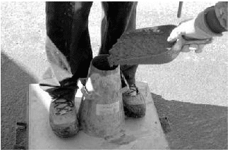
To perform the slump test, the cone, shown in Figures 1 and 2, is dampened and placed on a flat, rigid, nonabsorbent surface. The technician stands on the mold’s foot pieces to hold the mold firmly in place while filling the mold in three layers of equal volume (see Figure 1). The first layer should fill the mold to a depth of about 2 ⅝ in. (67 mm), the second to 6 ⅛ in. (156 mm) and the top layer should slightly overfill the mold. Each layer is rodded 25 times with a round steel tamping rod to consolidate the grout before the next layer is placed.
The middle and top layers are rodded through the depth of the layer, penetrating into the layer below. If the grout level falls below the top of the cone while rodding the top layer, grout is added to keep excess grout heaped above the top of the mold at all times. After the top layer is rodded, any excess grout is struck off flush with the top of the cone. Any grout which accumulates around the base of the mold is removed so that it does not interfere with the movement of the slumping grout.
Immediately after striking off and clearing grout from the base of the mold, the mold is lifted in 3 to 7 seconds by raising it vertically using a steady upward lift. The mold should not be twisted or moved sideways during lifting.
The slump is the vertical distance between the top of the cone and the displaced original center of the top surface of the specimen, as shown in Figure 2.
The entire test must be completed within 2 ½ minutes, from start of mold filling to measurement. If there is a decided falling away or shearing off of grout from one side or portion of the grout mass, the test should be disregarded and repeated with a fresh grout sample.
Figure 1—Filling the Slump Cone
Figure 2—Measuring Grout Slump for Conventional Grout
COMPRESSIVE STRENGTH TESTING
When grout compressive strength testing is required, the procedures of ASTM C 1019, Standard Test Method for Sampling and Testing Grout (ref. 3) are used. The Standard contains procedures for both field and laboratory grout compression testing and can be used either to help select grout proportions during preconstruction or as a quality control test for grout preparation uniformity during construction.
When used as part of a quality assurance program, the number of grout samples to be tested should be specified before the start of construction. One grout sample, as previously described, is used to make three compressive strength specimens. Grout specimens are formed in molds made from concrete masonry units with the same absorption and moisture content characteristics as those being used on the job (see Figures 3, 4).
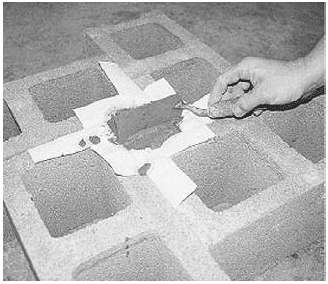
Because the absorption characteristics of the grout mold must be similar to those experienced by the grout in the wall, when walls are constructed using both concrete and clay masonry units, the grout mold is constructed using both types of units, as shown in Figure 4.
The molds should be located where they can remain undisturbed for 24 to 48 hours, in a level area free from perceptible vibration.
Units for the mold are laid out to form a space with a square cross section, 3 in. (76 mm) or larger on each side, with a height twice its width. Nonabsorbent spacers are placed at the bottom of the square space if needed to achieve the required specimen height. Permeable liners, such as paper towels, are taped to the surrounding masonry units to break the bond between the grout specimen and the masonry units, but still allow water to be absorbed into the units.
Grout is poured into the mold in two lifts of approximately equal depth, with each layer rodded 15 times to eliminate any air bubbles, distributing the strokes uniformly over the cross section of the mold. When rodding the upper layer, the rod should penetrate about ½ in. (13 mm) into the bottom layer. After the upper layer is rodded, the top of the specimen is leveled with a straight edge as shown in Figure 5, such that there are no projections or depressions exceeding ⅛ in. (3.2 mm). The specimen is then immediately covered with damp fabric or similar material to promote curing.
Within 30 minutes of filling the mold, grout is added to completely fill any depression which may have formed due to initial water absorption. The top of the specimen is leveled again and re-covered to keep it damp until testing.
The specimens should remain undisturbed until the molds are removed, and should be protected from temperature extremes. After 24 to 48 hours, the molds are removed and the specimens are carefully packed for transport, keeping them damp, and shipped to the laboratory for testing.
Within 8 hours of removing the molds, laboratory personnel should store the specimens in a moist room, moist cabinet or water storage tank prior to testing.
Specimen width, height and out-of-plumb are measured and recorded. Average widths are used to calculate the average cross-sectional area, which is used to determine compressive strength based on the maximum compressive load.
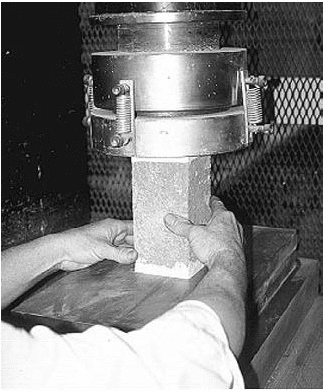
Prior to testing, the specimens should be capped in accordance with the applicable provisions of ASTM C 617, Standard Method of Capping Cylindrical Concrete Specimens, (ref. 6), and tested according to ASTM C 39, Standard Method of Test for Compressive Strength of Molded Concrete Cylinders (ref. 7) (see Figure 6). More detail on the test method and procedures are included in ASTM C 1019.
When approved, other methods of obtaining grout samples, such as drilling cores, may be used to test grout compressive strength. Because test results vary with the method of forming the specimen and with specimen geometry, these test results cannot be directly compared unless previous testing has established a relationship between the two methods of forming and specimen geometries.
Concrete test methods should not be used for grout as they do not simulate water absorption into masonry units. Grout cubes or cylinders formed in nonabsorptive molds will give unreliable results.
Figure 3—Grout Mold for Compressive Strength Testing with Concrete Masonry Units
Figure 4—Grout Mold Constructed Using Concrete Masonry and Clay Brick
Figure 5—Leveling the Top of the Grout Specimen
Figure 6—Capped Grout Specimen Being Placed In Compression Testing Machine
SELF-CONSOLIDATING GROUTS
Self-consolidating grout (SCG) is a highly fluid and stable grout mix that is easy to place and does not require consolidation or reconsolidation. SCG is similar in nature to conventional grout, although the mix design is significantly different: proportions of constituent materials are highly controlled and admixtures (typically in the form of superplasticizers with or without viscosity modifiers) are used to produce a plastic grout with desired properties. Controlled aggregate gradation is also important to maintain fluidity without segregation, to produce a mix that results in consistent properties throughout the grout lift.
Because of the fluid nature of the material, traditional measures of consistency and flow such as the slump cone test (ASTM C 143) are not applicable to SCG.
SCG is a relatively new material, which is not yet incorporated into building codes and standards. To date, compliance has been achieved in several cases by using the grout demonstration panel option in Specification for Masonry Structures (ref. 5). Quality assurance provisions are being developed. It is anticipated that SCG testing procedures will be similar to those for self-consolidating concrete, as the two materials are very similar.
REFERENCES
Grout for Concrete Masonry, TEK 09-04A. Concrete Masonry & Hardscapes Association, 2005.
Masonry mortars are composed of cementitious materials, aggregates, water, and admixtures when specified. Cementitious materials include portland cement, masonry cement, mortar cement, slag cement, blended hydraulic cement, hydraulic cement, quicklime, hydrated lime and lime putty. Aggregates consist of natural sand or manufactured sand. Admixtures may include such materials as coloring pigments, water repellent agents, accelerators, retarders and air-entraining agents. These materials are described in Mortars for Concrete Masonry, TEK 09-01A (ref. 1).
Quality assurance testing of site-prepared mortar is fairly uncommon, except on large jobs or for essential facilities. When mortar testing is required, it is essential that all parties involved possess a thorough knowledge of the mortar specifications, test methods and standard industry practices. Misinterpretations of these standards can result in improper testing and confusion regarding compliance with specifications.
Typically, project specifications require mortar to comply with Standard Specification for Mortar for Unit Masonry, ASTM C270 (ref. 2). Two methods of demonstrating compliance with ASTM C270 are permitted: the proportion specification or the property specification. Note that these compliance options are completely independent of each other; the requirements from one should not be used in conjunction with the other. Of the two options, the proportion specification is much more commonly used. TEK 09-01A covers the proportion specification in detail.
Although physical testing of the mortar is not required to demonstrate compliance with the proportion specification, the mortar is often tested to verify consistency throughout the job, most often by cone penetration or compressive strength testing. The property specification requires testing to be performed on laboratory-prepared mortar to demonstrate compliance with a specified minimum compressive strength, minimum water retention and maximum air content. This information is required for submittals, so is performed prior to construction. Where special inspection is required in accordance with the International Building Code (ref. 3), the special inspector, as part of his duties, is required to verify compliance with the approved mix proportions for field-prepared mortar. Both consistency testing and testing to verify compliance with the property specification are covered in this TEK.
Field-prepared and preconstruction mortar should be evaluated using Standard Test Method for Preconstruction and Construction Evaluation of Mortars for Plain and Reinforced Unit Masonry, ASTM C780 (ref. 4), which includes the following test methods: consistency by cone penetration; consistency retention by cone penetration; consistency by modified concrete penetrometer; mortar-aggregate ratio and water content; air content; and compressive strength. Note that mortar compressive strength is not an accurate indication of mortar strength in the wall, nor of the masonry wall compressive strength. This is discussed in detail in the section Compressive Strength Testing of Field-Prepared Mortar, below.
Note that the physical properties of these field mortar evaluations cannot be compared to the values required by the ASTM C270 property specification. In fact, ASTM does not publish minimum compressive strength requirements for field-prepared mortar.
When fresh mortar is placed on concrete masonry units during construction, its characteristics immediately begin to change due to water absorption by the masonry units. Nearly all of the available mortar test methods, however, are performed on mortar before it comes into contact with masonry units. Therefore, the properties of the sampled and tested mortar can be expected to differ significantly from mortar in contact with masonry units. Because conditions of the units and environment can vary greatly from job to job, the properties of the plastic mortar may need to vary as well to ensure quality construction. For this reason, no pass/fail criteria exist for field tests of mortar.
Standard Guide for Quality Assurance of Mortars, ASTM C1586 (ref. 5) provides guidance on the proper use of ASTM C270 and C780 for evaluating masonry mortar produced in the laboratory and at the construction site.
MORTAR CONSISTENCY
The most important aspect of mortar quality control is consistency throughout the construction project. The test methods outlined in ASTM C780 are intended to evaluate that consistency. Test results acquired throughout construction are compared to a baseline preconstruction evaluation.
The cone penetration test offers a quantitative measure of mortar consistency. Test values indicate the mortar workability, which may be affected by water content, aggregate properties, batch properties and other factors. Tested values are likely to change throughout a project’s duration due to variable site conditions as well as variations in masonry unit moisture content and absorption characteristics.
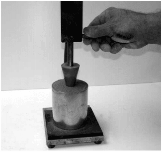
Cone penetration tests are performed by dropping a conical plunger from a specified height into a measured mortar sample and measuring the resulting depth of penetration, as shown in Figure 1.
Figure 1—Mortar Consistency as Measured Using Cone Penetrometer
MORTAR AGGREGATE RATIO
Mortar quality assurance often includes verification that mortar materials are proportioned as specified. ASTM C780 Annex A4 provides a method for sampling mortar from the field and determining the ratio of aggregate to cementitious material in the sample by weight. The mortar sample is passed through a No. 100 (150-µm) sieve to determine the percentage of material coarser than 150-µm. These results are compared to a sieve analysis of the aggregate used in the mortar to determine what fraction of the material passing the sieve is aggregate, and what fraction is cementitious material.
To complete the calculations in the test method, the mortar water content must also be determined, as detailed in Annex A4.
MORTAR COMPRESSIVE STRENGTH TESTING
One of the most universally recognized properties of masonry is compressive strength. While this property may not be the most important for masonry mortar, it is often perceived as such because compressive strength values are generally understood and are relatively easy to determine. Confusion and misinterpretation sometimes exist, however, when interpreting project specification requirements for mortar strength because there are several different compressive strength test methods included in ASTM Standards and model building codes. These methods were established to address specific needs, and they differ from each other in test requirements for obtaining, conditioning and testing mortar samples and specimens. Note that the mortar compressive strength determined in a laboratory is not indicative of either the strength of the mortar in the wall, nor of the masonry (i.e., wall) compressive strength. Specification for Masonry Structures (ref. 6) includes two alternatives for documenting masonry compressive strength; one based on the type of mortar and the compressive strength of the masonry units; the other based on compression testing of masonry prisms.
Compressive Strength Testing of Laboratory-Prepared mortar
Verifying compliance to the ASTM C270 property specification requires mortar compressive strength to be tested in accordance with Standard Test Method for Compressive Strength of Hydraulic Cement Mortars (Using 2-in. or 50-mm Cube Specimens), ASTM C 109 (ref. 7), with modifications regarding specimen storage and conditioning.
Compressive strength testing in accordance with ASTM C270 is conducted on specimens that are proportioned, mixed and conditioned in the testing laboratory. Water content of the mortar sample is such that the mortar flow must be 110 ± 5%. Compressive strength test specimens are 2 in. (51 mm) mortar cubes cast in nonabsorbent molds (see Figure 2) and cured in a moist room or moist cabinet meeting the requirements of ASTM C511, Standard Specification for Mixing Rooms, Moist Cabinets, Moist Rooms and Water Storage Tanks Used in the Testing of Hydraulic Cements and Concretes (ref. 9), until tested.
ASTM test methods emphasize the importance of extreme care in observing the testing procedures used to verify C270 requirements. According to Note 8 of ASTM C109: “Reliable strength results depend upon careful observance of all the specified requirements and procedures. Erratic results at a given test period indicate that some of the requirements and procedures have not been carefully observed, for example, those covering the testing of the specimens as prescribed in 10.6.2 and 10.6.3. Improper centering of specimens resulting in oblique fractures or lateral movement of one of the heads of the testing machine during loading will cause lower strength results.”
To facilitate centering the test specimens, the compression testing machine is required to have a spherically-seated upper bearing block attached at the center of the upper head. The bearing surface diagonal or diameter is required to be only slightly greater than the diagonal or diameter of the specimen.
Figure 2—Striking Off Mortar Cube Specimens for Compressive Strength Testing
Compressive Strength Testing of Field-Prepared Mortar
Compressive strength is one of the most commonly tested properties of field mortar. The test, described in ASTM C780, provides an indication of mortar consistency during construction, not as an indication of the compressive strength of the masonry, or even of the mortar in the wall. Compressive strength test results should be compared on a periodic basis to evaluate uniformity. These test results can be compared to preconstruction test results of similarly prepared mortar to provide a reference to a preapproved laboratory-prepared mortar strength.
Knowledgeable interpretations of results are necessary. As an example, consider the mortar’s water to cement ratio, which can have a significant effect on the tested strength. Mortar on site is adjusted to accommodate field conditions: on a hot sunny day, the mason may desire a more plastic mortar with a higher water content. Mortar sampled on this day will have a lower tested compressive strength than a similar mortar sampled on a cooler, damper day, which would likely be mixed using less water. However, the end result—the condition of the mortar in the wall—may be very comparable. These factors must be accounted for when interpreting compressive strength test results of field-prepared mortar.
Note that the results of these evaluations are not representative of the strength of the mortar in the wall, rather, they represent approximate mortar strengths only. The tested compressive strength of field-mixed mortar may be significantly less than that of hardened mortar joints for several reasons.
Mortar specimens are cast in nonabsorbent forms, whereas mortar in the wall is exposed to the suction from absorbent masonry units, reducing the water to cement ratio, which in turn increases the compressive strength.
The aspect ratio of the test specimens is greater than that of mortar joints. The typical mortar joint, at ⅜ in. (9.5 mm) high with a depth of at least 1 in. (25 mm), results in a broad, stable configuration that is naturally able to carry more load than the comparatively taller and more slender mortar specimens used for material evaluation. When tested at an aspect ratio of ⅜:1, tested mortar compressive strength values are routinely 8,000 to 10,000 psi (55.16 to 68.95 MPa).
For these reasons as well as others, field mortar compressive strength test results should never be compared to the requirements in ASTM C270 Table 2, which apply to laboratory-prepared mortar only.
ASTM C780 permits the use of cube or cylinder molds. Cylinder molds of 2 or 3 in. (51 or 76 mm) diameter have heights twice their diameter. Due to the higher aspect ratio of cylinder specimens, tests on cylindrical specimens result in tested compressive strength values approximately 15% less than those of cube specimens of the same mortar. If cylinder test results are to be directly compared to those for cubes, correction factors should be applied to the cylinder specimen results.
Immediately after sampling the mortar, it is placed in the molds, consolidated and covered to prevent evaporation per the procedures dictated by C780. The filled molds are stored for 24 hours in conditions as close to laboratory conditions as possible, at which point they are transported to the laboratory and stored in a moist room for another 24 hours. The specimens are then stripped of their molds and stored in the moist room or closet until 2 hours prior to compressive strength testing.
Prior to testing, mortar cylinders are capped with a gypsum or sulfur capping compound to provide uniform parallel bearing surfaces. Mortar cubes, however, are tested without caps, as the molded cube surfaces provide a smooth and uniform bearing surface. The specimens are tested in a moist condition. The axis of the specimen is aligned with the center of thrust of the spherically-seated (upper) bearing block of the compression machine. Load is applied to the specimen continuously and without shock until failure, and the compressive strength, type of failure, and appearance of the mortar is reported.
Uniform Building Code Standard 21-16, Field Test Specimens For Mortar (ref. 10), contained another method to obtain mortar compressive strength test specimens. This method prescribes ½ to ⅝ in. (13 to 16 mm) thickness of mortar to be spread on a masonry unit and allowed to stand for one minute. The mortar is then removed from the unit and placed in a cube or cylinder for compressive strength testing. The test method, however, is no longer used or referenced in current codes and standards and would not provide results that can be compared to C270 properties.
WATER RETENTION
The property specification of ASTM C270 requires a minimum water retention of 75% when tested in accordance with Standard Test Method for Water Retention of Hydraulic Cement-Based Mortars and Plasters, ASTM C1506 (ref. 15). This test was developed to measure the ability of a mortar to retain its mix water under the suction of the adjacent masonry unit. A certain amount of water absorption by the unit is beneficial, but too much may be detrimental.
Water retention is determined in the laboratory by measuring the mortar’s “initial flow,” and “flow after suction.” Initial flow is the percent increase in diameter of a mortar sample when it is placed on a flow table and dropped 25 times in 15 seconds. The same procedure is used to determine flow after some of the mortar’s mix water has been removed by an applied vacuum, which is meant to simulate the suction of masonry units on mortar. Water retention is the ratio of flow after suction to initial flow, expressed as a percentage.
AIR CONTENT
The ASTM C270 property specification includes a limit on the mortar air content. In general, greater air contents result in greater mortar durability and workability, but reduced mortar bond strength.
Air content is determined in accordance with ASTM C91, with the exception that the laboratory-prepared mortar is required to be of the materials and proportions used in the construction. The air content of the mortar is determined by calculation using the weight of a sample of mortar and accounting for all of the materials used. The calculation requires precise measurements of all materials and a knowledge of the specific gravity of those materials.
ASTM C780 also includes procedures for determining mortar air content using a pressure or volumetric method, either of which can be used in repetitive tests to evaluate the effects of changes in mixing time, mixing procedures, or other variables.
FLEXURAL BOND STRENGTH
ASTM C1329 Standard Specification for Mortar Cement (ref. 11) covers additional requirements for masonry mortars using mortar cement as a cementitious material. Although mortar cement is similar to masonry cement, it must achieve a minimum bond strength and must meet a lower air content than masonry cement. Mortar cement is permitted to be used in buildings assigned to Seismic Design Categories D, E or F, whereas masonry cement and Type N mortar cannot be used as part of the lateral force-resisting system for these buildings (ref. 12). Compliance testing for flexural bond strength is conducted in accordance with ASTM C1072 Standard Test Method for Measurement of Masonry Flexural Bond Strength (ref. 13). This method relies in turn on Standard Test Methods for Evaluating Masonry Bond Strength, ASTM C1357 (ref. 14). C1357 uses a prism constructed of “standard masonry units,” defined for this use as solid 3⅝ x 2¼ x 7⅝ in. (92 x 57 x 194 mm) units. Mortar bond is determined by calculating the modulus of rupture based on wrenching units from the prism using a bond wrench testing apparatus. C1072 includes detailed requirements for aggregates, mix design, manufacturing, size, curing and moisture content of the “standard” concrete masonry units used to determine compliance.
REFERENCES
Mortars for Concrete Masonry, TEK 09-01A. Concrete Masonry & Hardscapes Association, 2004.
Standard Specification for Mortar for Unit Masonry, ASTM C270-14. ASTM International, Inc., 2014.
International Building Code. International Code Council, 2012.
Standard Test Method for Preconstruction and Construction Evaluation of Mortars for Plain and Reinforced Unit Masonry, ASTM C780-14. ASTM International, Inc., 2014.
Standard Guide for Quality Assurance of Mortars, ASTM C1586-05(2011). ASTM International, Inc., 2011.
Specification for Masonry Structures, TMS 602-13/ACI 530.1-13/ASCE 6-13. Reported by the Masonry Standards Joint Committee, 2013.
Standard Test Method for Compressive Strength of Hydraulic Cement Mortars (Using 2-in. or 50-mm Cube Specimens), ASTM C109/C109M-13. ASTM International, Inc., 2013.
Standard Specification for Masonry Cement, ASTM C91/C91M-12. ASTM International, Inc., 2012.
Standard Specification for Mixing Rooms, Moist Cabinets, Moist Rooms and Water Storage Tanks Used in the Testing of Hydraulic Cements and Concretes, ASTM C511-13. ASTM International, Inc., 2013.
Field Test Specimens for Mortar, UBC Standard 21-16, International Conference of Building Officials, 1994.
Standard Specification for Mortar Cement, ASTM C1329/C1329M-12. ASTM International, Inc., 2012.
Building Code Requirements for Masonry Structures, TMS 402-13/ACI 530-13/ASCE 5-13. Reported by the Masonry Standards Joint Committee, 2013.
Standard Test Method for Measurement of Masonry Flexural Bond Strength, ASTM C1072-13e1. ASTM International, Inc., 2013.
Standard Test Methods for Evaluating Masonry Bond Strength, ASTM C1357-09. ASTM International, Inc., 2009.
Standard Test Method for Water Retention of Hydraulic Cement-Based Mortars and Plasters, ASTM C1506-09. ASTM International, Inc., 2009.
Concrete masonry is a popular building material in part because of its strength, versatility, durability, economy and resistance to fire, impact, noise and termites. To function as designed, however, concrete masonry buildings must be constructed properly.
Concrete masonry is used in projects ranging from small single story buildings to multistory loadbearing projects and is used in every building type and occupancy, including institutional, residential, commercial and manufacturing facilities. Because of the varying nature of these facilities, masonry construction continues to evolve, becoming more detailed and multifaceted. Reinforced masonry requires masons to not only lay masonry units, but to also properly place reinforcing steel and grout. As the intricacy and variety of masonry systems continues to expand, so does the need for educated and knowledgable inspectors to verify that masonry is being constructed as designed. Likewise, ensuring that the physical properties of the masonry materials comply with project specifications requires detailed knowledge of testing procedures.
Many masonry projects of substantial size requires the implementation of a quality assurance program. A quality assurance program includes the owner’s or designer’s efforts to require a specified level of quality and to determine the acceptability of the final construction. As part of a quality assurance program, inspection includes the actions taken to ensure that the established quality assurance program is met. As a counterpart to inspection, quality control includes the contractor’s or manufacturer’s efforts to ensure that the final properties of a product achieve a specified goal under a quality assurance program. Together, inspection and quality control comprise the bulk of the procedural requirements of a typical quality assurance program.
INSPECTION
Inspection is one part of a quality assurance program, which are the administrative and procedural requirements set up by the architect or engineer to assure the owner that the project is constructed in accordance with the contract documents. Inspection is one means of verifying that the project is constructed as designed using the specified materials.
Inspection assures that masonry materials and construction practices comply with the requirements of the contract documents. Inspectors, the inspection program, and inspection records should be addressed in the quality assurance program. Local municipalities may have minimum inspection requirements that augment or complement minimum code requirements to ensure the safety of the public. Additionally, the amount of inspection required depends on the owner’s needs. The architect or engineer will typically specify the degree of inspection necessary to meet the owner’s quality assurance program, local ordinances and code requirements. (See Required Levels of Inspection below.)
Concrete Masonry Inspectors
A variety of individuals may review the progress of masonry construction. The mason, general contractor, and often the architect, engineer and owner will periodically observe the progress to verify that the masonry construction is proceeding as planned. Municipal or jurisdictional building inspectors may also be required to verify that the constructed project meets local building code requirements. In addition to these individuals, special masonry inspectors are sometimes required by the local building code or by the owner through the architect or engineer.
Each of these “inspectors” tends to look at the masonry construction differently. For example, architects, owners, and masons and general contractors may focus on aesthetic aspects of the masonry, such as color of units, color and size of mortar joints, tolerances, etc. Municipal building inspectors and engineers may concentrate more on verifying structural-related items, such as proper connections, reinforcing steel size and location and connector spacing. Individuals designated as masonry inspectors also closely inspect structural-related items but may also inspect aesthetic, weatherproofing and serviceability aspects of the masonry project as outlined in the contract documents.
The following helps address the level of inspection that may be required by masonry inspectors. It can also serve as a guide for engineers, architects, contractors and building officials engaged in masonry construction or inspection.
Required Levels of Inspection
Local municipalities may have minimum inspection requirements to ensure public safety. Additionally, the amount of inspection required depends on the owner’s needs. The architect or engineer will typically specify the degree of inspection necessary to meet the owner’s quality assurance program and local code requirements.
How long an inspector should be on a job site and what should be inspected has, however, been a source of confusion in many areas of the country. To clarify how much inspection should be required on masonry projects, Specification for Masonry Structures (ref. 1) includes detailed inspection guidelines that provide an excellent basis for the degree of inspection that should be provided on masonry projects.
The 2003 International Building Code (IBC) (ref. 2) Section 1704.5 inspection requirements are virtually identical to those in Specification for Masonry Structures. The corresponding designations are:
IBC special inspection Level 1 requirements correspond to Specification for Masonry Structures Level B.
IBC special inspection Level 2 requirements correspond to Specification for Masonry Structures Level C.
Although there is no special inspection requirement corresponding to Specification for Masonry Structures Level A, this basic requirement is covered in IBC section 109.
In addition, in the 2002 edition of Specification for Masonry Structures the three levels of quality assurance were designated Levels 1, 2 and 3, which were replaced by Levels A, B and C, respectively, in the 2005 edition. This change in nomenclature is wholly editorial and does not affect the requirements specified for each level.
Three levels of inspection are defined within Specification for Masonry Structures:
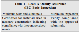
Level A (IBC Basic) – These requirements are the least stringent, requiring verification that the masonry construction complies with the plans and specifications (see Table 1). This level of inspection can only be applied to empirically designed masonry, glass unit masonry and masonry veneer used in facilities defined as nonessential by the building code. When masonry is designed by engineered methods or is part of an essential facility, Level B or C inspection is required.
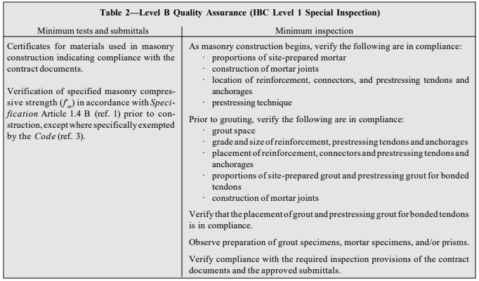
Level B (IBC Level 1) – These requirements provide a periodic-type inspection for engineered masonry used in nonessential facilities (as defined in the building code) and for empirically designed masonry, glass unit masonry and masonry veneer used in essential facilities. Key inspection items include assurance that required reinforcement, anchors, ties and connectors are in place and that appropriate grouting procedures are used (see Table 2).
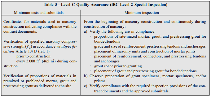
Level C (IBC Level 2) – The most comprehensive inspection procedures are required for essential facilities (as defined in the building code) that are designed by engineered design methods (see Table 3). Items inspected under a Level C quality assurance program are similar to those of Level B, with the added requirement that inspection be continuous during all phases of masonry construction.
These inspection levels are minimum criteria and may be increased when deemed necessary by the owner or designer. In this case, the contract documents must indicate the inspection level and tests that are required to assure that the masonry work conforms with the project requirements. Due to their relative importance or potential hazard, more significant inspection and quality assurance measures are required for essential facilities.
Table 1—Level A Quality Assurance (IBC Basic Inspection)
Table 2—Level B Quality Assurance (IBC Level 1 Special Inspection)
Table 3—Level C Quality Assurance (IBC Level 2 Special Inspection)
Responsibilities and Qualifications of Masonry Inspectors
Proper construction techniques are essential for a building to function as designed. Unfortunately, buildings are sometimes poorly constructed because of oversight, miscommunication, or occasionally because of unscrupulous behavior. Accordingly, inspection of the construction process can be vital to the success of a project.
An inspector’s main duty is to observe the construction to verify that the materials and completed project are, to the best of the inspector’s knowledge, in conformance wit h the contract documents and applicable building code. The inspector is not required to determine the adequacy of either the design or application of products and cannot revoke or modify any requirement nor accept or reject any portion of the work. To function effectively, the inspector must be familiar with proper construction techniques and materials, with the requirements of the local building codes, Building Code Requirements for Masonry Structures (ref. 3) and Specification for Masonry Structures. Although not required by Specification for Masonry Structures or the International Building Code, inspectors may be qualified or certified under nationally recognized education programs offered through such organizations as the International Code Council. Completion of such a program may be required by a local jurisdiction or by a building official.
Although vague, Section 1704.1 of the 2003 International Building Code provides general guidance on the minimum qualifications for inspectors, as follows:
“The special inspector shall be a qualified person who shall demonstrate competence, to the satisfaction of the building official, for inspection of the particular type of construction or operation requiring special inspection.”
The nonspecific nature of this code provision has been a source of confusion on various construction projects due to the wide variety of interpretations of a ‘qualified person.’ Some equate qualification with a nationally recognized certification, while others have allowed a noncertified individual with sufficient experience to serve as an inspector.
As a minimum, however, a masonry inspector must be familiar with masonry construction and be able to read plans and specifications effectively in order to judge whether the construction is in conformance with the contract documents. As part of this task, an inspector should always review the contract documents thoroughly before construction begins.
Inspectors must keep complete and thorough records of observations regarding the construction process. An effective way to accomplish this is by keeping a daily log when the inspector visits the project. Items such as the date, weather, temperature, work in progress (location and what was accomplished), meetings (attendees and topics of discussion), as well as overall observations and test results should be recorded in a neat, orderly manner since these notes may be needed later.
At the completion of the project or at predetermined stages of construction, inspectors must submit a signed report stating whether the construction requiring inspection was, to the best of the inspector’s knowledge, in conformance with the contract documents and applicable workmanship standards. Specific services and duties required by an inspection agency are outlined in Article 1.6 B of Specification for Masonry Structures.
TESTING AND QUALITY CONTROL
Material testing may be necessary either before, during or after the construction of a building. For example, preconstruction testing may be requested to verify compliance of materials with the contract documents and is typically the responsibility of the contractor or producer of the product. Testing during construction, as part of the owner’s quality assurance program, may also be required to ensure that materials supplied throughout the construction process comply with the contract documents. These tests are the owner’s responsibility. Additionally, testing may be necessary to determine the in-place condition of the building materials after the building is complete or during the building’s life.
Standards for sampling and testing concrete masonry materials and assemblages are developed by the technical committees of ASTM International in accordance with consensus procedures. These standards reflect the expertise of researchers, concrete masonry manufacturers, designers, contractors and others with an interest in quality standards for masonry.
Specific testing procedures for concrete masonry units and related materials are covered in detail in references 4 through 8.
REFERENCES
Specification for Masonry Structures, ACI 530.1-05/ASCE 6-05/TMS 602-05. Reported by the Masonry Standards Joint Committee, 2005.
2003 International Building Code. International Code Council, 2003.
Building Code Requirements for Masonry Structures, ACI 530-05/ASCE 5-05/TMS 402-05. Reported by the Masonry Standards Joint Committee, 2005.
Evaluating the Compressive Strength of CM based on 2012IBC/2011 MSJC, TEK 18-01B, Concrete Masonry & Hardscapes Association, 2011.
Sampling and Testing Concrete Masonry Units, TEK 1802C, Concrete Masonry & Hardscapes Association, 2014.
Prestressing is the general term used when a structural element is compressed prior to being subjected to building loads. This initial state of compression offsets tensile stresses from applied loads. Post-tensioning is a specific method of prestressing where tendons are stressed after the wall has been placed. The other type of prestressing, called pretensioning, involves tensioning the tendon prior to construction of the masonry. Because virtually all prestressed masonry built to date has been post-tensioned, the two terms are often used interchangeably as they apply to this form of masonry design and construction.
Post-tensioned concrete masonry walls have been built for schools, retail, manufacturing, highway sound barriers, warehouses and other types of structures. In addition, posttensioning has been used to strengthen and repair existing masonry walls. This TEK addresses new concrete masonry walls laid in running bond and built with unbonded vertical posttensioning tendons. Post-Tensioned Concrete Masonry Wall Design, TEK 14-20A (ref. 1) addresses the structural design of vertically post-tensioned walls.
POST-TENSIONING
In post-tensioned construction, hollow concrete masonry units are laid conventionally and prestressing tendons are either placed in the concrete masonry cells or in the cavity between multiple wythes. Current design codes (ref. 3) typically address post-tensioning of masonry walls laid in running bond. The cells or cavity containing the tendons may or may not be grouted. Grouting helps increase cross-sectional area for shear and compressive resistance, but increases construction cost and time.
Prestressing tendons are either installed during wall construction, or access ports are left in the walls so the tendons can be slipped in after the walls are completed. In either case, the tendons are tensioned only after the walls have cured for approximately three to seven days.
MATERIALS
Construction of a post-tensioned wall proceeds similarly to that of conventional masonry. The materials are the same, with the addition of hardware to develop the posttensioning forces, steel prestressing tendons which can be wires, bars or strands, and sometimes prestressing grout.
Concrete Masonry Units
Open-ended (Aand H-shaped) concrete masonry units (Figure 1) are particularly suited to post-tensioned masonry, as these units can be placed around the tendons without having to lift the units over the tendons. While these two-core units are commonly used, proprietary units are also being developed that are specifically intended for use with tendons.
The net area strength of concrete masonry units must be at least 1,900 psi (13.1 MPa) per Standard Specification for Loadbearing Concrete Masonry Units (ref. 2). However, stronger units are often specified for post-tensioned walls to utilize the higher compressive strength.
Mortar and Grout
Type S mortar is commonly used for conventional loadbearing masonry, and Type S is a good choice for posttensioned masonry as well. Higher early strength mortars can accommodate earlier stressing.
Because mortar must be placed on concrete masonry webs adjacent to grouted cores to contain the fluid grout, full mortar bedding is sometimes specified when grout is used. Mortar bedding is a design issue as well, as the section properties of a wall with face shell mortar bedding are different from those of a fully bedded wall.
Because this TEK addresses unbonded tendons only, the grout discussed here is conventional grout (ASTM C 476, ref. 6), not prestressing grout. Prestressing grout is only used with bonded tendons. Encasing tendons in conventional grout restrains the tendons, but they are still considered unbonded.
Tendons
In the United States, tendons are usually high-strength bars joined by couplers, although Building Code Requirements for Masonry Structures (ref. 3) also allows steel strands or wires to be used. Couplers allow the use of shorter bars which minimizes the height of lifting. To date, there are no code provisions for tendons which are not steel.
Important features of the tendons are their size, strength, and relaxation characteristics. Most tendons currently available in the United States are bars between 7/16 and 1 in. (11 and 25 mm) in diameter, with strengths between 60,000 and 100,000 psi (413 and 690 MPa), depending on the supplier. Steel strand tendons are generally 270,000 psi (1,860 MPa). Tendons are usually placed in hollow cells of masonry units with little or no grouting, except for certain shear walls (these must be identified on the design drawings). In addition, the open-ended units shown in Figure 1 must be grouted to meet minimum web requirements in ASTM C 90 (ref. 2).
Tendon Corrosion Protection
Tendons must be protected from moisture deterioration, and the design documents should indicate the type of protection required. Tendons in walls with a likelihood of high moisture levels (single wythe exterior walls in areas of high humidity and interior walls around swimming pools, locker rooms, etc.) must have corrosion protection in addition to that provided by the masonry cover, such as hot-dipped galvanizing (ref. 3). In practice, most prestressing tendons are supplied with a hotdipped galvanized coating. It is considered good practice to use additional corrosion protection, such as flexible epoxy-type coatings, for tendons in moist environments.
Grouting
While the need for grouting is minimized compared to conventionally reinforced walls, grout is still needed for mild reinforcement, anchorages for the tendons, such as in bond beams, and tendon restraints.
Anchorages
Each tendon is anchored at the foundation and extends to the top of the wall. Building Code Requirements for Masonry Structures (ref. 3) requires that tendons be anchored by mechanical embedments or bearing devices or by bond development in concrete. Tendons can not be anchored by bond development into the masonry. The foundation anchorage is embedded in the wall or footing while the top anchorage utilizes a special block, a precast concrete spreader beam or a grouted bond beam.
Unless the design documents call out specific bottom anchors, the contractor must select the anchor appropriate to the conditions. The cast-in-place bottom anchor (Figure 2a) is preferred for shear walls and for fire walls. While they are the best anchors for capacity, cast-in-place anchors are the most difficult to align. Cast-in-place anchors are often set by the foundation contractor, not the mason. Thus, quality control is a concern with these anchors.
The mason controls bottom anchor placement when either adhesive anchors are installed in the foundation (Figure 2c), or when an anchor is used which does not rely on the foundation for support (Figure 2b). If the anchor in Figure 2b is used, foundation dowels are grouted into the wall to lock it in place. In some instances, tendons can also begin at an upper floor and not at the foundation. In this case, the foundationless anchor is used with a bond beam, similar to Figure 2b.
The mechanical post-installed anchors can be used for nearly all applications, while the adhesive type should not be used for fire walls.
CONSTRUCTION
Key steps of post-tensioning concrete masonry walls include: selecting and setting the bottom anchorages; installing the tendons; selecting and setting the top anchorages; and a tensioning the tendons.
Bottom Anchors
Bottom anchors are most critical to the proper construction of post-tensioned walls. Alignment is essential to ensure that the tendons are placed exactly as intended.
Tendons
Tendons are usually placed concentric with the wall. However, they may be placed off-center to counteract bending moments due to eccentric vertical forces or lateral forces from a single direction. However, tendons should not be placed such that tensile stresses develop in the wall due to the combination of prestressing force and dead load.
Laterally-unrestrained tendons are free to move within the cell or cavity and are the simplest to construct. Laterally restrained tendons are not free to move within a cell or cavity. Restraint is accomplished by grouting the full height of the tendon or by providing intermittent restraints—either grout plugs or mechanical restraints—at the quarter points of the wall height.
Placing tendons is much like that of mild reinforcement. They may be installed after the masonry is constructed provided the design allows laterally-unrestrained tendons. If laterally restrained tendons are required, the tendon placement should proceed simultaneously with the masonry to allow the restraints to be installed unless the cells will be grouted.
Tendon positioners (see Figure 3) are useful to maintain the tendon location within the wall during construction of the masonry. Positioners may also function as restraints if their capacity is determined by testing.
In all details, the tendons must be able to slip freely. If grout encases the tendon either totally or at restraints or bond beams, a bond breaker such as poly tape should be used to allow the tendon to slip.
Tendons can also be either bonded or unbonded. Bonded tendons are encapsulated by prestressing grout in a corrugated duct which is bonded to the surrounding masonry by grout. Both the prestressing grout inside the duct and the grout around the duct must be cured before the tendons are stressed. Thus, bonded tendons are also laterally-restrained. All other tendons are unbonded. However, unbonded tendons may be either laterally-restrained or unrestrained. Walls with laterally unrestrained and unbonded tendons do not require grouting and are generally the most economical to construct. However, the wall performance will not be as good as with laterally restrained tendons. The designer must specify which system will be used.
For some conditions, primarily seismic, grouted conventional reinforcement is used in addition to post-tensioning tendons to provide minimum requirements of bonded reinforcement. However, post-tensioned walls are most economical when the grouting is minimized or eliminated totally in comparison to a conventionally reinforced wall. The higher cost of the post-tensioning materials is more than offset by the savings of placing fewer tendons compared to reinforcing bars and eliminating most of the grouting.
Top Anchors
The top anchor must be placed on solid masonry, a grouted bond beam or a precast concrete unit. The anchor should not be supported by mortar.
Figure 4 shows a means for supporting the top of a wall when the top anchor is placed on a bond beam in a lower course. This detail can also be used for interior partitions.
Tensioning
At the time the tendons are stressed, the masonry is considered to have its initial strength (f ‘mi). The project specification should include either the minimum f ‘mi and minimum specified compressive strength of masonry ( f ‘m), or the amount of curing required before stressing can occur.
The sequence of tensioning, whether it is accomplished by fully stressing each tendon sequentially or by stressing the tendons in stages, is a function of the design specifications. Prestressed masonry design, and therefore the structural integrity of these walls, relies on an accurate measure of the prestress in the tendons. To ensure the required level of accuracy, Specification for Masonry Structures (ref. 4) requires that the following two methods be used to evaluate the tendon prestressing force:
1. measure the tendon elongation and compare it with required elongation based on average load-elongation curves for the prestressing tendons, and either:
2a. use a calibrated dynamometer to measure the jacking force on a calibrated gage, or
2b. for prestressing tendons using bars of less than 150 ksi (1,034 MPa) tensile strength, use load-indicating washers complying with Standard Specification for Compressible-Washer-Type Direct Tension Indicators for Use with Structural Fasteners, ASTM F 959 (ref. 5). If the two values determined by methods 1 and 2 are not within 7 percent of each other, the cause of the difference must be corrected.
QUALITY ASSURANCE
Post-tensioned walls must be constructed in conformance with masonry standards applicable to conventionally reinforced masonry. In addition to these, Specification for Masonry Structures (ref. 4) requires the following for posttensioned masonry:
In the out-of-plane direction, the tolerance for the tendon placement shall be + 1/4 in. (6 mm) for masonry beams, columns, walls, and pilasters with cross-sectional dimensions less than 8 in. (203 mm). For cross-sectional dimensions greater than 8 in. (203 mm), the tolerance increases to + 3/8 in. (10 mm).
In the in-plane direction, the tolerance for tendon placement is +1in. (25 mm).
If tolerances exceed these amounts, the Architect/Engineer should evaluate the effect on the structure.
Standard Specification for Loadbearing Concrete Masonry Units, ASTM C 90-01a. ASTM International, 2001.
Building Code Requirements for Masonry Structures, ACI 530-02/ASCE 5-02/TMS 402-02. Reported by the Masonry Standards Joint Committee, 2002.
Specification for Masonry Structures, ACI 530.1-02/ASCE 6-02/TMS 602-02. Reported by the Masonry Standards Joint Committee, 2002.
Standard Specification for Compressible-Washer- Type Direct Tension Indicators for Use with Structural Fasteners, ASTM F 959-01a. ASTM International, 2001.
Standard Specification for Grout for Masonry, ASTM C 476-01. ASTM International, 2001.