Resources

Concrete Masonry Basement Wall Construction

Introduction

Basements allow a building owner to significantly increase usable living, working, or storage space at a relatively low cost. Old perceptions of basements have proven outdated by stateofthe-art waterproofing, improved drainage systems, and natural lighting features such as window wells. Other potential benefits of basements include room for expansion of usable space, increased resale value, and safe haven during storms.

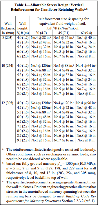
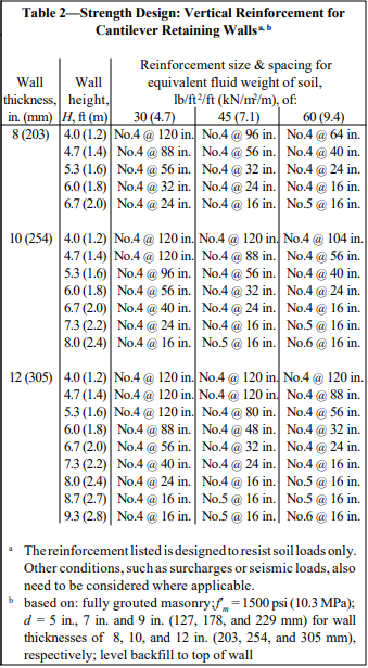
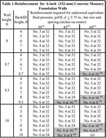
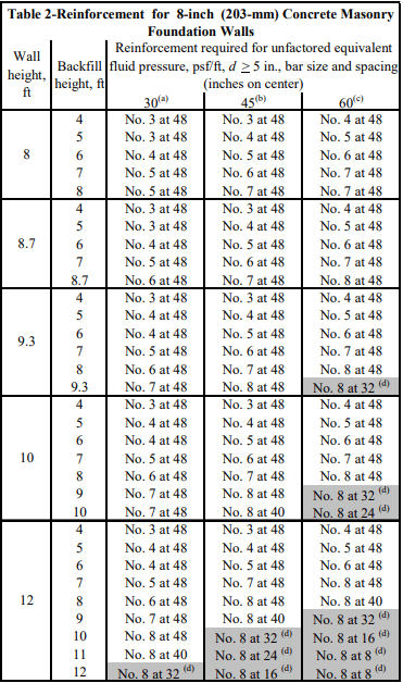
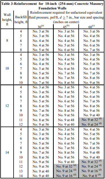
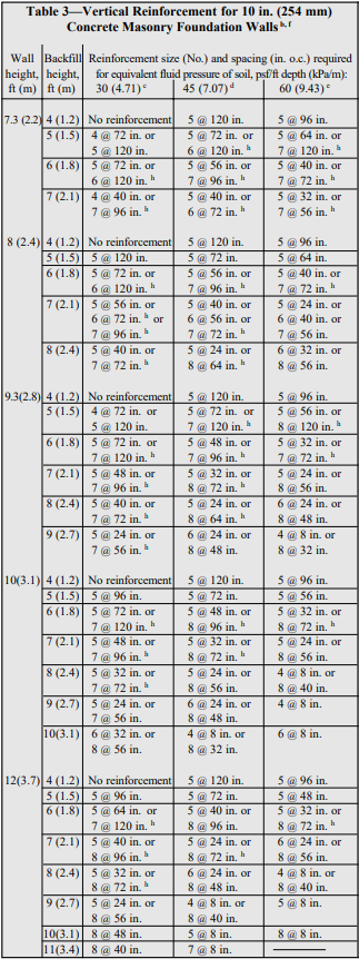
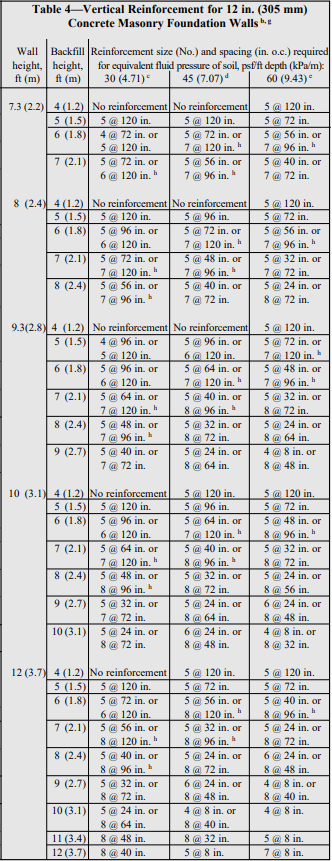
Historically, plain (unreinforced) concrete masonry walls have been used to effectively resist soil loads. Currently, however, reinforced walls are becoming more popular as a way to use thinner walls to resist large backfill pressures. Regardless of whether the wall is plain or reinforced, successful performance of a basement wall relies on quality construction in accordance with the structural design and the project specifications.

Materials

Concrete Masonry Units: Concrete masonry units should comply with Standard Specification for Loadbearing Concrete Masonry Units, ASTM C 90 (ref. 8). Specific colors and textures may be specified to provide a finished interior to the basement. Drywall can also be installed on furring strips, if desired. A rule of thumb for estimating the number of concrete masonry units to order is 113 units for every 100 ft2 (9.3 m2) of wall area. This estimate assumes the use of 3/8 in. (9.5 mm) mortar joints.

Mortar: Mortar serves several important functions in a concrete masonry wall; it bonds the units together, seals joints against air and moisture penetration, and bonds to joint reinforcement, ties, and anchors so that all components perform as a structural element.

Mortar should comply with Standard Specification for Mortar for Unit Masonry, ASTM C 270 (ref. 9). In addition, most building codes require the use of Type M or S mortar for construction of basement walls (refs. 2, 4, 5, 9, 13), because Type M and S mortars provide higher compressive strengths. Table 1 lists mortar proportions.

Typical concrete masonry construction uses about 8.5 ft3 (0.24 m3) of mortar for every 100 ft2 (9.3 m2) of masonry wall area. This figure assumes 3/8 in. (9.5 mm) thick mortar joints, face shell mortar bedding, and a 10% allowance for waste.

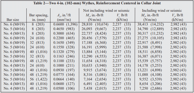
Grout: In reinforced concrete masonry construction, grout is used to bond the reinforcement and the masonry together. Grout should conform to Standard Specification for Grout for Masonry, ASTM C 476 (ref. 10), with the proportions listed in Table 2. As an alternative to complying with the proportion requirements in Table 2, grout can be specified to have a minimum compressive strength of 2000 psi (13.8 MPa) at 28 days. Enough water should be added to the grout so that it will have a slump of 8 to 11 in. (203 to 279 mm). The high slump allows the grout to be fluid enough to flow around reinforcing bars and into small voids. This initially high water-to-cement ratio is reduced significantly as the masonry units absorb excess mix water. Thus, grout gains high strengths despite the initially high waterto-cement ratio.

Construction

Prior to laying the first course of masonry, the top of the footing must be cleaned of mud, dirt, ice or other materials which reduce the bond between the mortar and the footing. This can usually be accomplished using brushes or brooms, although excessive oil or dirt may require sand blasting.

Masons typically lay the corners of a basement first so that alignment is easily maintained. This also allows the mason to plan where cuts are necessary for window openings or to fit the building’s plan.

To make up for surface irregularities in the footing, the first course of masonry is set on a mortar bed joint which can range from 1/4 to 3/4 in. (6.4 to 19 mm) in thickness. This initial bed joint should fully bed the first course of masonry units, although mortar should not excessively protrude into cells that will be grouted.

All other mortar joints should be approximately 3/8 in. (9.5 mm) thick and, except for partially grouted masonry, need only provide face shell bedding for the masonry units. In partially grouted construction, webs adjacent to the grouted cells are mortared to restrict grout from flowing into ungrouted cores. Head joints must be filled solidly for a thickness equal to a face shell thickness of the units.

Tooled concave joints provide the greatest resistance to water penetration. On the exterior face of the wall, mortar joints may be cut flush if parging coats are to be applied.

When joint reinforcement is used, it should be placed directly on the block with mortar placed over the reinforcement in the usual method. A mortar cover of at least 5/8 in. (15.9 mm) should be provided between the exterior face of the wall and the joint reinforcement. A mortar cover of 1/2 in. (12.7 mm) is needed on the interior face of the wall. For added safety against corrosion, hot dipped galvanized joint reinforcement is recommended.

See Figures 1-4 for construction details.

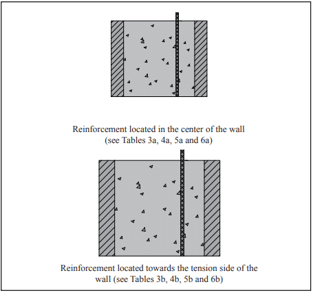
Reinforced Masonry: For reinforced masonry construction, the reinforcing bars must be properly located to be fully functional. In most cases, vertical bars are positioned towards the interior face of basement walls to provide the greatest resistance to soil pressures. Bar positioners at the top and bottom of the wall prevent the bars from moving out of position during grouting. A space of at least 1/2 in. (12.7 mm) for coarse grout and 1/4 in. (6.4 mm) for fine grout should be maintained between the bar and the face shell of the block so that grout can flow completely around the reinforcing bars.

As mix water is absorbed by the units, voids can form in the grout. Accordingly, grout must be puddled or consolidated after placement to eliminate these voids and to increase the bond between the grout and the masonry units. Most codes permit puddling of grout when it is placed in lifts less than about 12 in. (305 mm). Lifts over 12 inches (305 mm) should be mechanically consolidated and then reconsolidated after about 3 to 10 minutes.

Surface Bonding: Another method of constructing concrete masonry walls is to dry stack units (without mortar) and then apply surface bonding mortar to both faces of the wall. The surface bonding mortar contains thousands of small glass fibers. When the mortar is applied properly to the required thickness, these fibers, along with the strength of the mortar itself, help produce walls of comparable strength to conventionally laid plain masonry walls. Surface bonded walls offer the benefits of excellent dampproof coatings on each face of the wall and ease of construction.

Dry-stacked walls should be laid in an initial full mortar bed to level the first course. Level coursing is maintained by using a rubbing stone to smooth small protrusions on the block surfaces and by inserting shims every two to four courses.

Water Penetration Resistance: Protecting below grade walls from water entry involves installation of a barrier to water and water vapor. An impervious barrier on the exterior wall surface can prevent moisture entry.

The barrier is part of a comprehensive system to prevent water penetration, which includes proper wall construction and the installation of drains, gutters, and proper grading.

Building codes (refs. 2, 4 , 5, 9, 13) typically require that basement walls be dampproofed for conditions where hydrostatic pressure will not occur, and waterproofed where hydrostatic pressures may exist. Dampproofing is appropriate where groundwater drainage is good, for example where granular backfill and a subsoil drainage system are present. Hydrostatic pressure may exist due to a high water table, or due to poorly draining backfill, such as heavy clay soils. Materials used for waterproofing are generally elastic, allowing them to span small cracks and accommodate minor movements.

When choosing a waterproof or dampproof system, consideration should be given to the degree of resistance to hydrostatic head of water, absorption characteristics, elasticity, stability in moist soil, resistance to mildew and algae, impact or puncture resistance, and abrasion resistance. A complete discussion of waterproofing, dampproofing, and drainage systems is included in TEK 19-03A (ref. 6).

All dampproofing and waterproofing systems should be applied to walls that are clean and free from dirt, mud and other materials which may reduce bond between the coating and the concrete masonry wall.

Draining water away from basement walls significantly reduces the pressure the walls must resist and reduces the possibility of water infiltration into the basement if the waterproofing (or dampproofing) system fails. Perforated pipe has historically proven satisfactory when properly installed. When placed on the exterior side of basement walls, perforated pipes are usually laid in crushed stone to facilitate drainage. To prevent migration of fine soil into the drains, filter fabrics are often placed over the gravel.

Drainage pipes can also be placed beneath the slab and connected into a sump. Pipes through the footing or the wall drain water from the exterior side of the basement wall.

The drainage and waterproofing systems should always be inspected prior to backfilling to ensure they are adequately placed. Any questionable workmanship or materials should be repaired at this stage since repairs are difficult and expensive after backfilling.

Backfilling: One of the most crucial aspects of basement construction is how and when to properly backfill. Walls should be properly braced or have the first floor in place prior to backfilling. Otherwise, a wall which is designed to be supported at the top may crack or even fail from the large soil pressures. Figure 5 shows one bracing scheme which has been widely used for residential basement walls. More substantial bracing may be required for high walls or large backfill pressures.

The backfill material should be free-draining soil without large stones, construction debris, organic materials, and frozen earth. Saturated soils, especially saturated clays, should generally not be used as backfill materials since wet materials significantly increase the hydrostatic pressure on the walls.

Backfill materials should be placed in several lifts and each layer should be compacted with small mechanical tampers. Care should be taken when placing the backfill materials to avoid damaging the drainage, waterproofing or exterior insulation systems. Sliding boulders and soil down steep slopes should thus be avoided since the high impact loads generated can damage not only the drainage and waterproofing systems but the wall as well. Likewise, heavy equipment should not be operated within about 3 feet (0.9 m) of any basement wall system.

The top 4 to 8 in. (102 to 203 mm) of backfill materials should be low permeability soil so rain water is absorbed into the backfill slowly. Grade should be sloped away from the basement at least 6 in. (152 mm) within 10 feet (3.1 m) of the building. If the ground naturally slopes toward the building, a shallow swale can be installed to redirect runoff.

Construction Tolerances

Specifications for Masonry Structures (ref. 8) specifies tolerances for concrete masonry construction. These tolerances were developed to avoid structurally impairing a wall because of improper placement.

  1. Dimension of elements in cross section or elevation
    …………………………………….¼ in. (6.4 mm), +½ in. (12.7 mm)
  2. Mortar joint thickness: bed………………………..+⅛ in. (3.2 mm)
    head………………………………..-¼ in (6.4 mm), + in. (9.5 mm)
  3. Elements
    • Variation from level: bed joints……………………………………….
      ±¼ in. (6.4 mm) in 10 ft (3.1 m), ±½ in. (12.7 mm) max
      top surface of bearing walls……………………………………………..
      ±¼ in.(6.4 mm), +⅜ in.(9.5 mm), ±½ in.(12.7mm) max
    • Variation from plumb………….±¼ in. (6.4 mm) 10 ft (3.1 m)
      ………………………………………±⅜ in. (9.5 mm) in 20 ft (6.1 m)
      ……………………………………………±½ in. (12.7 mm) maximum
    • True to a line…………………..±¼ in. (6.4 mm) in 10 ft (3.1 m)
      ………………………………………±⅜ in. (9.5 mm) in 20 ft (6.1 m)
      ……………………………………………±½ in. (12.7 mm) maximum
    • Alignment of columns and bearing walls (bottom versus top)
      ……………………………………………………………..±½ in (12.7 mm)
  4. Location of elements
    • Indicated in plan……………..±½ in (12.7 mm) in 20 ft (6.1 m)
      …………………………………………….±¾ in. (19.1 mm) maximum
    • Indicated in elevation
      ……………………………………….±¼ in. (6.4 mm) in story height
      …………………………………………….±¾ in. (19.1 mm) maximum

Insulation: The thermal performance of a masonry wall depends on its R-value as well as the thermal mass of the wall. Rvalue describes the ability to resist heat flow; higher R-values give better insulating performance. The R-value is determined by the size and type of masonry unit, type and amount of insulation, and finish materials. Depending on the particular site conditions and owner’s preference, insulation may be placed on the outside of block walls, in the cores of hollow units, or on the interior of the walls.

Thermal mass describes the ability of materials like concrete masonry to store heat. Masonry walls remain warm or cool long after the heat or air-conditioning has shut off, keeping the interior comfortable. Thermal mass is most effective when insulation is placed on the exterior or in the cores of the block, where the masonry is in direct contact with the interior conditioned air.

Exterior insulated masonry walls typically use rigid board insulation adhered to the soil side of the wall. The insulation requires a protective finish where it is exposed above grade to maintain durability, integrity, and effectiveness.

Concrete masonry cores may be insulated with molded polystyrene inserts, expanded perlite or vermiculite granular fills, or foamed-in-place insulation. Inserts may be placed in the cores of conventional masonry units, or they may be used in block specifically designed to provide higher R-values.

Interior insulation typically consists of insulation installed between furring strips, finished with gypsum wall board or panelling. The insulation may be fibrous batt, rigid board, or fibrous blown-in insulation.

Design Features

Interior Finishes: Split faced, scored, burnished, and fluted block give owners and designers added options to standard block surfaces. Colored units can be used in the entire wall or in sections to achieve specific patterns.

Although construction with staggered vertical mortar joints (running bond) is standard for basement construction, the appearance of continuous vertical mortar joints (stacked bond pattern) can be achieved by using of scored units or reinforced masonry construction.

Natural Lighting: Because of the modular nature of concrete masonry, windows and window wells of a variety of shapes and sizes can be easily accommodated, giving basements warm, natural lighting. For additional protection and privacy, glass blocks can be incorporated in lieu of traditional glass windows.

References

  1. Basement Manual-Design and Construction Using Concrete Masonry, CMU-MAN-002-01, Concrete Masonry & Hardscapes Association, 2001.
  2. BOCA National Building Code. Country Club Hills, IL: Building Officials and Code Administrators International, Inc. (BOCA), 1999.
  3. Building Code Requirements for Masonry Structures, ACI 530-02/ASCE 5-02/TMS 402-02. Reported by the Masonry Standards Joint Committee, 2002.
  4. International Residential Code. Falls Church, VA: International Code Council, 2000.
  5. International Building Code. Falls Church, VA: International Code Council, 2000.
  6. Preventing Water Penetration in Below-Grade Concrete Masonry Walls, TEK 19-03A. Concrete Masonry & Hardscapes Association, 2001.
  7. Seismic Design Provisions for Masonry Structures, TEK 14-18B, Concrete Masonry & Hardscapes Association, 2009.
  8. Specifications for Masonry Structures, ACI 530.1-02/ASCE 6-99/TMS 602-02. Reported by the Masonry Standards Joint Committee, 2002.
  9. Standard Building Code. Birmingham, AL: Southern Building Code Congress International, Inc. (SBCCI), 1999.
  10. Standard Specification for Grout for Masonry, ASTM C 476-01. American Society for Testing and Materials, 2001.
  11. Standard Specification for Load-Bearing Concrete Masonry Units, ASTM C 90-01. American Society for Testing and Materials, 2001.
  12. Standard Specification for Mortar for Unit Masonry, ASTM C 270-00. American Society for Testing and Materials, 2000.
  13. Uniform Building Code. Whittier, CA: International Conference of Building Officials (ICBO), 1997.

Design of Concrete Masonry Noncomposite (Cavity) Walls

INTRODUCTION

When selecting a building enclosure, concrete masonry cavity walls are considered to be one of the best solutions available for all types of buildings. From both an initial cost and life-cycle cost perspective, cavity wall construction is highly regarded as the prime choice in many applications.

Cavity walls typically consist of an inner wythe of concrete masonry units that are tied to an exterior wythe of architectural masonry units. The cavity space between the wythes is normally 2 to 4 ½ in. (51 to 114 mm) wide, easily accommodating rigid board insulation. The two wythes together provide a wall that is highly resistant to wind driven rain, absorbs and reflects sound, provides good thermal performance, and has excellent fire resistance characteristics.

Masonry walls constructed of two or more wythes can technically be classified in one of three ways, depending on how the wythes are designed and detailed. These wall types include composite, noncomposite and veneer assemblies. In noncomposite construction, covered in this TEK, each wythe is connected to the adjacent wythe with metal wall ties, but they are designed such that each wythe individually resists the loads imposed on it. Composite walls are designed so that the wythes act together as a single element to resist structural loads. This requires the masonry wythes to be connected by masonry headers or by a mortar- or grout-filled collar joint and wall ties (see ref. 4). In a veneer wall, the backup wythe is designed as the loadbearing system while the veneer provides a nonloadbearing architectural wall finish that transfers loads to the backup wythe through wall ties (see refs. 5, 6). Although Building Code Requirements for Masonry Structures (ref. 1) defines a cavity wall as a noncomposite masonry wall, the term cavity wall is also commonly used to describe a veneer wall with masonry backup.

This TEK illustrates the design of noncomposite concrete masonry walls based on Building Code Requirements for Masonry Structures (ref. 1), referred to here as the MSJC code. Each wythe of a noncomposite wall system can be designed to accommodate all types of loads, including gravity loads from roofs, walls and floors, as well as lateral loads from wind or earthquakes. The MSJC code design provisions are used to size these masonry walls.

STRUCTURAL DESIGN

The MSJC code includes noncomposite design provisions for both allowable stress design (Chapter 2) and empirical design (Chapter 5). The assumptions and relevant governing equations for each of these design approaches is given in references 2 and 3 respectively.

Concrete masonry cavity walls can be designed as either reinforced or unreinforced walls. For unreinforced design, flexural tensile stresses in masonry are resisted by bond developed between the masonry units and mortar; axial tension is not permitted (ref. 1). If direct axial tension is encountered in a design, reinforcement must be used. In reinforced masonry design, all tension is assumed to be resisted by reinforcement.

Empirical Design

Empirical design can be an expedient approach for typical loadbearing structures subjected to nominal wind loads (basic wind speed ≤ 110 mph, (177 km/h) (MSJC 5.1.2.2) and located in areas of low seismic risk, as it cannot be used for the design of seismic force resisting systems in SDC (Seismic Design Category) B or higher (MSJC 5.1.2.1). Empirical design utilizes prescriptive provisions, outlining criteria such as wall height to thickness ratios, minimum wall thickness and maximum building height.

References 1 and 3 contain maximum length-to-thickness or height-to-thickness ratios for empirically designed walls. When using these ratios for noncomposite multiwythe walls, the total wall thickness is taken as the sum of the nominal thicknesses of each wythe, neglecting the presence of any cavity thickness. Compressive stress is based on the gross cross-sectional area of all wythes, including hollow cells but not including the cavity between the wythes. When floor or roof loads are carried on only one wythe, only the gross cross-sectional area of that wythe is used to check the axial capacity. In addition, these walls must meet the following requirements for wall ties connecting the wythes:

  • wall ties of wire size W2.8 (3/16 in., MW 18), or metal wire of equivalent stiffness, spaced at a maximum of 24 in. (610 mm) o.c. vertically and 36 in. (914 mm) o.c. horizontally, with at least one wall tie for each 4½ ft² (0.42 m²) of wall area,
  • walls constructed with hollow units must use rectangular ties,
  • walls constructed with solid units must use Z-shaped ties with hooks at least 2 in. (51 mm) long,
  • wall ties may not have drips,
  • additional ties are required within 12 in. (305 mm) of all openings and must be spaced no more than 3 ft (914 mm) apart around the perimeter of the opening.

Requirements for bonding with joint reinforcement are the same as those for wall ties with the following exceptions: cross wire size may not be smaller than W1.7 (9 gage, MW 11) and the supported wall area per cross wire may not exceed 2 ft² (0.25 m²). In addition, the longitudinal wires must be embedded in mortar.

Allowable Stress Design

Similar to empirical design, MSJC allowable stress design includes prescriptive requirements for bonding wythes of noncomposite walls via wall ties, adjustable ties and joint reinforcement.

For rectangular ties, Z ties (for use with other than hollow units) and ladder or tab-type joint reinforcement, ties or cross wires of joint reinforcement, ties must be placed with a maximum spacing of 36 in. (914 mm) horizontally and 24 in. (610 mm) vertically. The minimum number of ties is one per:

  • 2 ft² (0.25 m²) of wall for wire size W 1.7 (9 gage, MW 11), and
  • 4½ ft² (0.42 m²) of wall for wire size W 2.8 (3/16 in., MW 18).

For adjustable ties, one tie must be provided for each 1.77 ft² (0.16 m²) of wall; maximum horizontal and vertical spacing is 16 in. (406 mm); misalignment of bed joints from one wythe to the other may not exceed 1 ¼ in. (31.8 mm); the maximum clearance between connecting parts of the tie is 1/16 in. (1.6 mm); and pintle ties must have at least two pintle legs of wire size W2.8 (3/16 in., MW 18) (see also Figure 1).

For noncomposite masonry walls, the following additional requirements apply.

  • Collar joints are not to contain headers, or be filled with mortar or grout.
  • Gravity loads from supported horizontal members are to be resisted by the wythe nearest the center of the span.
  • Bending moments about the weak axis of the wall and transverse loads are distributed to each wythe according to relative stiffness. This can be determined by:
    Wi = WT [EmIi/(EmIi+ EmI0)]
    Wo = WT [EmI0/(EmIi+ EmI0)]
  • Loads acting parallel to the wall are resisted by the wythe to which they are applied.
  • The cavity width between the wythes is limited to 4½ in. (114 mm) unless a detailed wall tie analysis is performed.

DESIGN EXAMPLES

The following examples illustrate the use of noncomposite masonry employing empirical and allowable stress design methods. Although there are no specific provisions in MSJC for noncomposite wall design using strength design, strength design could be used provided the same load distribution principles as presented for allowable stress design are employed.

Empirical Design Design Example:
Design the top story of a two-story noncomposite double wythe masonry wall system supported on continuous footings. Note that the design of the lower story, though not shown, is performed in the same manner, except that the floor live and dead loads from the upper story are also accounted for.

Given:

unsupported wall height= 10 ft (3.01 m)
superimposed gravity dead load= 220 plf (3.2 kN/m)
superimposed gravity live load= 460 plf (6.7 kN/m)
net superimposed uplift from wind= 120 plf (1.8 kN/m)
wind pressure= 24 psf (1,149 Pa)
eccentricity of all gravity loads= 0
f’m= 1,500 psi (10.3 MPa)
Em= 1,350 ksi (9,308 MPa)


Wall lateral support requirement: l/t or h/t < 18, so minimum required wall thickness = h/18
= 10 ft (12 in./ft)/18
= 6.7 in. (169 mm)

Try a 4-in. (102 mm) outer wythe and 6-in. (152 mm) inner wythe (providing a total nominal wall thickness of 10 in. (254 mm)), and check allowable axial compressive stress due to dead and live loads (gravity loads are carried by the inner wythe only):

dead:roof220 lb/ft
 wythe = 10 ft x 26 psf (ref. 8)260 lb/ft
live:roof460 lb/ft
total load: 940 lb/ft (13.7 kN/m)


Gross area of 6-in. (152-mm) wythe = 67.5 in.²/ft (ref. 7)
fa = 940 lb/ft/(67.5 in.²/ft) = 13.9 psi (0.096 MPa)
Fa = 75 psi (0.52 MPa) for Type M or S mortar, 70 psi (0.48 MPa) for Type N mortar (ref. 1)
fa < Fa (OK for all mortar types)

Per MSJC code section 5.8.3.1, the net uplift on the roof must be resisted by an anchorage system. Use a bond beam at the top of the inner wythe with vertical reinforcement to the foundation to provide this resistance.

ASD Reinforced Design Example:
Given:

unsupported wall height= 18 ft (5.5 m)
wind load, w= 36 psf (1,724 Pa)
net roof uplift at top of wall= 400 plf (5.8 kN/m) )
eccentricity of all vertical loads= 0
f’m= 1,500 psi (0.0718 MPa )
unit density= 115 pcf (1,842 kg/m³)
Grade 60 reinforcement 

Note: The 36 psf (1,724 Pa) wind load is much higher than is generally applicable when using empirical design.

Design the inside wythe first, as it must resist the uplift in addition to the flexural loads. Try two 6-in. (152 mm) wythes with No. 5 (M #16) reinforcement at 32 in. (813 mm) o.c.

Determine reinforcement needed for uplift at midheight:
uplift = 400 lb/ft – 34 lb/ft² (18 ft/2) = 94 lb/ft (1.37 kN/m) (ref. 8)
reinforcement needed = [(94 lb/ft)(32 in.)/(12 in./ft)]/[1.333(24,000 psi)] = 0.0078 in.²
As available for flexure = 0.31 – 0.0078 = 0.3022 in.²
Ms = FsAsjd = 1.333 (24,000 psi) (0.3022 in.²)(0.894)(2.813 in.)
= 24,313 lb-in. for 32 in. width
= 9,117 lb-in./ft (3,378 N⋅m/m) > 8,996 lb-in./ft (3,333 N⋅m/m), therefore Mm controls

Determine applied moment:
Since the wythes are identical, each would carry ½ the lateral load or ½ (36 psf) = 18 psf (124 kPa)
Mmax = wl²/8 = (18 psf)(18 ft)²(12 in./ft)/8
= 8,748 lb-in./ft (3,241 N⋅m/m) < 8,996 lb-in./ft (3,333 N⋅m/m) OK

Check shear:
Vmax = wl/2 = (18psf)(18 ft)/2 = 162 lb/ft (2.36 kN/m)
fv = Vmax/bd = 162 lb/ft/(12 in.)(2.813 in.) = 4.80 psi (33 kPa)
Fv = 37 x 1.333 = 51 psi (351 kPa)
4.80 psi (33 kPa) < 51 psi (351 kPa) OK

A quick check of the outside wythe shows that the same reinforcement schedule will work for it as well. Therefore, use two 6-in. (152-mm) wythes with No. 5 (M #16) vertical reinforcement at 32 in. (813 mm) o.c.

This wall could be designed using an unreinforced 4-in. (102 mm) outside wythe and a reinforced 8-in. (203-mm) inside wythe, with lateral loads distributed to each wythe according to the uncracked stiffness per MSJC section 1.9.2. Experience has shown, however, that the design would be severely limited by the capacity of the unreinforced outside wythe. Additionally, such a design could be used only in SDC A or B since 4-in. (102 mm) concrete masonry does not have cores large enough to reinforce.

Another alternative would be to design this system treating the 4 in. (102 mm) outer wythe as a nonloadbearing veneer. Designing this wall as a 4-in. (102 mm) veneer with an 8-in. (203 mm) reinforced structural backup wythe would result in No. 5 bars at 16 in. (M #16 at 406 mm) on center. This is the same amount of reinforcement used in the example above (two 6-in. (152 mm) wythes with No. 5 (M #16) at 32 in. (813 mm) on center). However, because the 6-in. (152 mm) units have smaller cores, 30% less grout is required.

The design using two 6-in. (152-mm) reinforced wythes has the following advantages over veneer with structural backup:

  • no limitation on SDC as when a veneer or an unreinforced outer wythe is used,
  • no limitation on wind speed as with a veneer,
  • equal mass on both sides of the wall permitting the use of the prescriptive energy tables for integral insulation, and
  • the flexibility of using units with different architectural finishes on each side.

NOMENCLATURE

As          = effective cross-sectional area of reinforcement, in.²(mm²)
b            = width of section, in. (mm)
d            = distance from extreme compression fiber to centroid of tension reinforcement, in. (mm)
Em         = modulus of elasticity of masonry, psi (MPa)
Es          = modulus of elasticity of steel, psi (MPa)
Fa          = allowable compressive stress due to axial load only, psi (kPa)
Fb          = allowable compressive stress due to flexure only, psi (kPa)
Fs          = allowable tensile or compressive stress in reinforcement, psi (kPa)
Fv          = allowable shear stress in masonry, psi (MPa)
fa           = calculated compressive stress in masonry due to axial load only, psi (kPa)
f’m         = specified compressive strength of masonry, psi (kPa)
h            = effective height, in. (mm)
fv           = calculated shear stress in masonry, psi (MPa)
Ii            = average moment of inertia of inner wythe, in.4/ft (m4/m)
Io           = average moment of inertia of outer wythe, in.4/ft (m4/m)
j             = ratio of distance between centroid of flexural compressive forces and centroid of tensile forces to depth d
k           = ratio of distance between compression face of wall and neutral axis to depth d
l            = clear span between supports, in. (mm)
M          = moment at the section under consideration, in.-lb/ft (N⋅m/m)
Mm       = flexural capacity (resisting moment) when masonry controls, in.-lb/ft (N⋅m/m)
Mmax   = maximum moment at the section under consideration, in.-lb/ft (N⋅m/m)
Ms        = flexural capacity (resisting moment) when reinforcement controls, in.-lb/ft (N⋅m/m)
t            = nominal thickness of a member, in. (mm)
Vmax    = maximum shear at the section under consideration, lb/ft (kN/m)
Wi        = percentage of transverse load on inner wythe
Wo       = percentage of transverse load on outer wythe
WT       = total transverse load
w         = wind pressure, psf (Pa)
ρ          = reinforcement ratio

REFERENCES

  1. Building Code Requirements for Masonry Structures, ACI 530-02/ASCE 5-02/TMS 402-02. Reported by the Masonry Standards Joint Committee, 2002.
  2. ASD of Concrete Masonry (2012 IBC & 2011 MSJC), TEK 14-07C, Concrete Masonry & Hardscapes Association, 2004.
  3. Empirical Design of Concrete Masonry Walls, TEK 1408B, Concrete Masonry & Hardscapes Association, 2003
  4. Structural Design of Unreinforced Composite Masonry, TEK 16-02B, Concrete Masonry & Hardscapes Association, 2001.
  5. Concrete Masonry Veneers, TEK 03-06C, Concrete Masonry & Hardscapes Association, 2012.
  6. Reinforced Composite Concrete Masonry Walls, TEK 1603B, Concrete Masonry & Hardscapes Association, 2006.
  7. Weights and Section Properties of Concrete Masonry Assemblies, CMU-TEC-002-23, Concrete Masonry & Hardscapes Association, 2023.


Reinforced Composite Concrete Masonry Walls

INTRODUCTION

Reinforced composite concrete masonry walls can provide geometric diversity. Composite walls consist of multiple wythes of masonry connected such that they act as a single structural member. There are prescriptive requirements in both the International Building Code (ref. 1) and Building Code Requirements for Masonry Structures (ref. 2) for connecting the wythes. General information on composite walls is included in TEK 16-01A, Multi-Wythe Concrete Masonry Walls (ref. 3) which is intended to be used in conjunction with this TEK.

Reinforced composite masonry walls are designed by the same procedures as all reinforced masonry walls. They must meet the same construction requirements for reinforcing placement, tolerances, grout placement, and workmanship as all reinforced concrete masonry walls.

Although composite walls can be reinforced or unreinforced, this TEK discusses the requirements for reinforced composite walls. Unreinforced composite walls are discussed in TEK 1602B, Structural Design of Unreinforced Composite Masonry (ref. 4).

DESIGN CONSIDERATIONS

Composite masonry is defined as “multicomponent masonry members acting with composite action” (ref. 2). For a multiwythe wall section to act compositely, the wythes of masonry must be adequately connected. Provisions for properly bonding the wythes are discussed in TEK 16-01A. When wall ties are used, the collar joint – the vertical space between the two wythes of masonry – must be filled solid with grout or mortar (refs. 1, 2). However, when reinforcement is placed in the collar joint, grout must be used to fill the collar joint.

Considerations When Choosing a Cross Section

Unlike single wythe walls, where the geometric cross section is set by the product as manufactured, the cross section of a composite wall is determined by the combination of units and collar joint which can theoretically be any thickness. Practically speaking, code, structural and architectural requirements will narrow the options for wall sections. In addition to structural capacity, criteria specific to cross-section selection for reinforced composite walls include:

• location of reinforcement in collar joint or in unit cores;

• collar joint thickness;

• unit selection for each wythe.

Structural Reinforcement Location

The engineer has the option of locating the structural reinforcing steel in the collar joint or in one or both wythes. While there is no direct prohibition against placing reinforcement in both the collar joint and the unit cores, practically speaking there is rarely a structural reason to complicate the cross section with this configuration.

With some units, it may be easier to install reinforcement in the collar joint, such as when both wythes are solid or lack sufficient cell space for reinforcing bars. Depending on the units selected, the collar joint may or may not provide the option to center the reinforcement within the wall cross section. For example, when the units are not the same thickness, the collar joint does not necessarily span the center of the section.

Conversely, if off-set reinforcing is preferred, perhaps to accommodate unbalanced lateral loads, it may be benefi cial to place the vertical bars in the unit cores. Placing reinforcement in the unit cores permits a thinner collar joint and possibly a thinner overall cross-section. Unit cores may provide a larger and less congested opening for the reinforcing bars and grout since the collar joint will be crossed with connecting wall ties. There is also the possibly that for a given geometry, centered reinforcement does end up in a core space.

Reinforcement can also be placed in the cells of each wythe, providing a double curtain of steel to resist lateral loads from both directions, as in the case of wind pressure and suction.

Collar Joint Width

There are no prescriptive minimums or maximums explicit to collar joint thickness in either Building Code Requirements for Masonry Structures or the International Building Code, however there are some practical limitations for constructability and also code compliance in reinforcing and grouting that effect the collar joint dimension. Many of these are covered in TEK 16-01A but a few key points from the codes that are especially relevant for reinforced composite masonry walls included below:

  • Wall tie length: Noncomposite cavity walls have a cavity thickness limit of 4½ in. (114 mm) unless a wall tie analysis is performed. There is no such limitation on width for filled collar joints in composite construction since the wall ties can be considered fully supported by the mortar or grout, thus eliminating concern about local buckling of the ties. Practically speaking, since cavity wall construction is much more prevalent, the availability of standard ties may dictate collar joint thickness maximums close to 4½ in. (114 mm).
  • Pour and lift height: Since the collar joint must be fi lled, the width of the joint infl uences the lift height. Narrow collar joints may lead to low lift or pour heights which could impact cost and construction schedule. See Table 1 in TEK 03-02A, Grouting Concrete Masonry Walls (ref. 5) for more detailed information.
  • Course or fine grout: Codes require a minimum clear distance of ¼-in. (6.3-mm) for fine grout and ½-in. (13-mm) for coarse grout between reinforcing bars and any face of the masonry unit.
  • Course or fine grout: Codes require a minimum clear distance of ¼-in. (6.3-mm) for fine grout and ½-in. (13-mm) for coarse grout between reinforcing bars and any face of the masonry unit.
  • Grout or mortar fill: Although codes permit collar joints to be filled with either mortar or grout, grout is preferred because it helps ensure complete filling of the collar joint without creating voids. Note that collar joints less than ¾ in. (19 mm), unless otherwise required, are to be filled with mortar as the wall is built. Increasing the slump of the mortar to achieve a solidly filled joint is preferred. This effectively requires a ¾-in. (19-mm) minimum on collar joints with structural reinforcing since it is also a code requirement that reinforcing bars be placed in grout, not mortar.
  • Reinforcing bar diameter: The reinforcing bar diameter cannot exceed one-half the least clear dimension of the collar joint.
  • Horizontal bond beams: Bond beams may be required to meet prescriptive code requirements such as seismic detailing. The collar joint then must be wide enough to accommodate the horizontal and vertical reinforcement along with the accompanying clearances for embedment in grout.  

Unit Selection for Each Wythe

Aesthetic criteria may play a primary role in unit selection for reinforced composite walls. Designing the composite wall to match modular dimensions may make detailing of interfaces much easier. Window and door frames, foundations, connectors and other accessories may coordinate better if typical masonry wall thicknesses are maintained. Additional criteria that influence the selection of units for reinforced composite walls include:

  • Size and number of reinforcing bars to be used and the cell space required to accommodate them.
  • Cover requirements (see ref. 6) may come into play when reinforcement is placed in the cells off-center. Cover requirements could affect unit selection, based on the desired bar placement; face shell thickness and cell dimensions.
  • If double curtains of vertical reinforcement are used, it is preferable to use units of the same thickness to produce a symmetrical cross section.

Structural Considerations

Some structural considerations were addressed earlier in this TEK during the discussion of cross section determination. Since reinforced composite masonry by definition acts as one wall to resist loads, the design procedures are virtually the same as for all reinforced masonry walls. TEK 14-07C, ASD of Concrete Masonry (2012 IBC & 2011 MSJC) (ref. 7) details design procedures. A few key points should be stressed, however:

  • Analysis: Empirical design methods are not permitted to be used for reinforced multiwythe composite masonry walls.
  • Section properties: Section properties must be calculated using the transformed section method described in TEK 1601A (ref. 3).
  • Shear stresses: Shear stress in the plane of interface between wythes and collar joint is limited to 5 psi (34.5 kPa) for mortared collar joints and 10 psi (68.9 kPa) for grouted collar joints.

DESIGN TABLES

Design tables for select reinforced composite walls are included below. The tables include maximum bending moments and shear loads that can be sustained without exceeding the allowable stresses defined in the International Building Code and Building Code Requirements for Masonry Structures. These can be compared to Tables 1 and 2 of TEK 14-19B, ASD Tables for Reinforced CM Walls (2012 IBC & 2011 MSJC) (ref. 8) for wall subjected to uniform lateral loads to ensure the wall under consideration is not loaded beyond its design capacity. The examples are based on the following criteria:

The examples are based on the following criteria:

• Allowable stresses:

In addition to these tables, it is important to check all code requirements governing grout space dimensions and maximum reinforcement size to ensure that the selected reinforcing bar is not too large for the collar joint. The designer must also check shear stress at the unit/grout interface to ensure it does not exceed the code allowable stress for the design loading.

CONSTRUCTION AND DETAILING REQUIREMENTS

With composite wall construction, the two masonry wythes are not required to be built at the same time unless the collar joint is less than ¾ in. (19 mm), as the code mandates that those collar joints be mortared as the wall is built. Practically speaking it is easier to build both wythes at the same time to facilitate placing either the grout or the mortar in the collar joint at the code required pour heights.

It can be more complex to grout composite walls. Consider that a composite wall may have requirements to grout the collar joint for the full wall height and length but the cores of the concrete masonry units may only need to be partially grouted at reinforcing bar locations. Installing reinforcement and grout in the collar joint space can also be more time-consuming because of congestion due to the wall ties.

Nonmodular composite wall sections may cause diffi culty at points where they interface with modular elements such as window and door frames, bonding at corners and bonding with modular masonry walls. 

NOTATIONS

As     = effective cross-sectional area of reinforcement, in.²/ft (mm²/m)
d       = distance from extreme compression fiber to centroid of tension reinforcement, in. (mm)
Eg     = modulus of elasticity of grout, psi (MPa)
Em    = modulus of elasticity of masonry in compression, psi (MPa)
Es     = modulus of elasticity of steel, psi (MPa)
Fb     = allowable compressive stress due to flexure only, psi (MPa)
Fs     = allowable tensile or compressive stress in reinforcement, psi (MPa)
Fv     = allowable shear stress in masonry, psi (MPa)
f’g     = specified compressive strength of grout, psi (MPa)
f’m    = specified compressive strength of masonry, psi (MPa)
Mr    = resisting moment of wall, in.-lb/ft (kNm/m)
Vr     = resisting shear of wall, lb/ft (kN/m)

REFERENCES

  1. International Building Code 2003. International Code Council, 2003.
  2. Building Code Requirements for Masonry Structures, ACI 530-05/ASCE 5-05/TMS 402-05. Reported by the Masonry Standards Joint Committee, 2005.
  3. Multi-Wythe Concrete Masonry Walls, TEK 16-01A. Concrete Masonry & Hardscapes Association, 2005.
  4. Structural Design of Unreinforced Composite Masonry, TEK 16-02B, Concrete Masonry & Hardscapes Association, 2001
  5. Grouting Concrete Masonry Walls, TEK 03-02A, Concrete Masonry & Hardscapes Association, 2005.
  6. Steel Reinforcement for Concrete Masonry, TEK 12-04D, Concrete Masonry & Hardscapes Association, 2006.
  7. ASD of Concrete Masonry (2012 IBC & 2011 MSJC), TEK 14-07C, Concrete Masonry & Hardscapes Association, 2004.
  8. ASD Tables for Reinforced CM Walls (2012 IBC & 2011 MSJC), TEK 14-19B, Concrete Masonry & Hardscapes Association, 2011.

Concrete Masonry Cantilever Retaining Walls

INTRODUCTION

Using concrete masonry in retaining walls, abutments and other structural components designed primarily to resist lateral pressure permits the designer and builder to capitalize on masonry’s unique combination of structural and aesthetic features—excellent compressive strength; proven durability; and a wide selection of colors, textures and patterns. The addition of reinforcement to concrete masonry greatly increases the tensile strength and ductility of a wall, providing higher load resistance.

In cantilever retaining walls, the concrete base or footing holds the vertical masonry wall in position and resists overturning and sliding caused by lateral soil loading. The reinforcement is placed vertically in the cores of the masonry units to resist the tensile stresses developed by the lateral earth pressure.

DESIGN

Retaining walls should be designed to safely resist overturning and sliding due to the forces imposed by the retained backfill. The factors of safety against overturning and sliding should be no less than 1.5 (ref. 7). In addition, the bearing pressure under the footing or bottom of the retaining wall should not exceed the allowable soil bearing pressure.

Recommended stem designs for reinforced cantilever retaining walls with no surcharge are contained in Tables 1 and 2 for allowable stress design and strength design, respectively. These design methods are discussed in detail in ASD of Concrete Masonry (2012 IBC & 2011 MSJC), TEK 14-07C, and Strength Design Provisions for Concrete Masonry, TEK 14-04B (refs. 5, 6).

Figure 1 illustrates typical cantilever retaining wall detailing requirements.

DESIGN EXAMPLE

The following design example briefly illustrates some of the basic steps used in the allowable stress design of a reinforced concrete masonry cantilever retaining wall.

Example: Design the reinforced concrete masonry cantilever retaining wall shown in Figure 2. Assume level backfill, no surcharge or seismic loading, active earth pressure and masonry laid in running bond. The coefficient of friction between the footing and foundation soil, k1, is 0.25, and the allowable soil bearing pressure is 2,000 psf (95.8 kPa) (ref. 7).

a. Design criteria:

Wall thickness = 12 in. (305 mm)
f’m = 1,500 psi (10.3 MPa)

Assumed weights:
Reinforced masonry: 130 pcf (2,082 kg/m³) (solid grout to increase overturning and sliding resistance)
Reinforced concrete: 150 pcf (2,402 kg/m³)

Required factors of safety (ref. 7)
F.S. (overturning) = 1.5
F.S. (sliding) = 1.5

b. Rankine active earth pressure

c. Resisting moment (about toe of footing)

Component weights:
masonry: (0.97)(8.67 ft)(130 pcf) = 1,093 lb/ft (16 kN/m)
earth: (2.69)(8.67 ft)(120 pcf) = 2,799 lb/ft (41 kN/m)
footing: (1.0)(5.33 ft)(150 pcf) = 800 lb/ft (12 kN/m)

Weight (lb/ft)XArm (ft)=Moment (ft-lb/ft)
masonry:1,093X2.67=2,918
earth:2,799X3.98=11,140
footing:800X2.67=2,136
4,69216,194
Total resisting moment16,194 ft-lb/ft
Overturning moment– 5,966 ft-lb/ft
10,228 ft-lb/ft (45.5 kN m/m)

d. Check factors of safety (F.S.)

F.S. (overturning)
= total resisting moment about toe/overturning moment
= 14,670/5,966
= 2.4 > 1.5 O.K.

e. Pressure on footing

f. Determine size of key

Passive lateral soil resistance = 150 psf/ft of depth and may be increased 150 psf for each additional foot of depth to a maximum of 15 times the designated value (ref. 7). The average soil pressure under the footing is: ½ (1,356 + 404) = 880 psf (42.1 kPa).

Equivalent soil depth: 880 psf/120 pcf = 7.33 ft (2.23 m)

Pp = (150 psf/ft)(7.33 ft) = 1,100 psf (52.7 kPa)

For F.S. (sliding) = 1.5, the required total passive soil resistance is: 1.5(1,851 lb/ft) = 2,776 lb/ft (41 kN/m)

The shear key must provide for this value minus the frictional resistance: 2,776 – 1,248 = 1,528 lb/ft (22 kN/m).

Depth of shear key = (1,528 lb/ft)/(1,100 psf) = 1.39 ft (0.42 m), try 1.33 ft (0.41 m).

At 1.33 ft, lateral resistance = (1,100 psf) + (150 psf/ft)(1.33 ft) = 1,300 lb/ft (19 kN/m)
Depth = (1,528 lb/ft)/[½ (1,100 + 1,300)] = 1.27 ft (0.39 m) < 1.33 ft (0.41 m) O.K.

g. Design of masonry

Tables 1 and 2 can be used to estimate the required reinforcing steel based on the equivalent fluid weight of soil, wall thickness, and wall height. For this example, the equivalent fluid weight = (Ka)(º) = 0.33 x 120 = 40 pcf (6.2 kN/m³).

Using allowable stress design (Table 1) and the conservative equivalent fluid weight of soil of 45 pcf (7.1 kN/m³), this wall requires No. 6 bars at 16 in. o.c. (M #19 at 406 mm o.c.). Using strength design (Table 2), this wall requires No. 5 bars at 16 in. o.c. (M #16 at 406 mm o.c.).

h. Design of footing

The design of the reinforced concrete footing and key should conform to American Concrete Institute requirements. For guidance, see ACI Standard 318 (ref. 2) or reinforced concrete design handbooks.

CONSTRUCTION

Materials and construction practices should comply with applicable requirements of Specification for Masonry Structures (ref. 4), or applicable local codes.

Footings should be placed on firm undisturbed soil, or on adequately compacted fill material. In areas exposed to freezing temperatures, the base of the footing should be placed below the frost line. Backfilling against retaining walls should not be permitted until the masonry has achieved sufficient strength or the wall has been adequately braced. During backfilling, heavy equipment should not approach closer to the top of the wall than a distance equal to the height of the wall. Ideally, backfill should be placed in 12 to 24 in. (305 to 610 mm) lifts, with each lift being compacted by a hand tamper. During construction, the soil and drainage layer, if provided, also needs to be protected from saturation and erosion.

Provisions must be made to prevent the accumulation of water behind the face of the wall and to reduce the possible effects of frost action. Where heavy prolonged rains are anticipated, a continuous longitudinal drain along the back of the wall may be used in addition to through-wall drains.

Climate, soil conditions, exposure and type of construction determine the need for waterproofing the back face of retaining walls. Waterproofing should be considered: in areas subject to severe frost action; in areas of heavy rainfall; and when the backfill material is relatively impermeable. The use of integral and post-applied water repellents is also recommended. The top of masonry retaining walls should be capped or otherwise protected to prevent water entry.

REFERENCES

  1. Building Code Requirements for Masonry Structures, ACI 530-05/ASCE 5-05/TMS 402-05. Reported by the Masonry Standards Joint Committee, 2005.
  2. Building Code Requirements for Structural Concrete and Commentary, ACI 318-02. Detroit, MI: American Concrete Institute, 2002.
  3. Das, B. M. Principles of Foundation Engineering. Boston, MA: PWS Publishers, 1984.
  4. Specification for Masonry Structures, ACI 530.1-05/ASCE 6-05/TMS 602-05. Reported by the Masonry Standards Joint Committee, 2005.
  5. ASD of Concrete Masonry (2012 IBC & 2011 MSJC), TEK 14-07C, Concrete Masonry & Hardscapes Association, 2004.
  6. Strength Design Provisions for Concrete Masonry, TEK 14-04B, Concrete Masonry & Hardscapes Association, 2008.
  7. 2003 International Building Code. International Code Council, 2003.

NOTATIONS

a     length of footing toe, in. (mm)
B     width of footing, ft (m)
d     distance from extreme compression fiber to centroid of tension reinforcement, in. (mm)
e       eccentricity, in. (mm)
F.S.  factor of safety
f’m     specified compressive strength of masonry, psi (MPa)
H       total height of backfill, ft (m)
I         moment of inertia, ft4 (m4)
Ka      active earth pressure coefficient
k1       coefficient of friction between footing and foundation soil
M       maximum moment in section under consideration, ft-lb/ft (kN⋅m/m)
Pa       resultant lateral load due to soil, lb/ft (kN/m)
Pp       passive earth pressure, lb/ft (N/m)
p         pressure on footing, psf (MPa)
T         thickness of wall, in. (mm)
t          thickness of footing, in. (mm)
W       vertical load, lb/ft (N/m)
x         location of resultant force, ft (m)
º         density of soil, pcf (kg/m³)
¤         angle of internal friction of soil, degreesDisclaimer: Although care has been taken to ensure the enclosed information is as accurate and complete as possible, NCMA does not assume responsibility for errors or omissions resulting from the use of this TEK.

Strength Design of Reinforced Concrete Masonry Foundation Walls

INTRODUCTION

Although concrete masonry foundation walls can be constructed without reinforcing steel, reinforcement may be required for walls supporting large soil backfill loads. The strength design provisions found in Chapter 3 of Building Code Requirements for Masonry Structures (ref. 1) typically provides increased economy over the allowable stress design method, as thinner walls or larger reinforcing bar spacings often result from a strength design analysis. Strength design criteria are presented in detail in TEK 14-04B, Strength Design Provisions for Concrete Masonry (ref. 2).

DESIGN LOADS

Soil imparts lateral loads on foundation walls. The load is assumed to increase linearly with depth, resulting in a triangular load distribution on the wall. This lateral soil load is expressed as an equivalent fluid pressure, with units of pounds per square foot per foot of depth (kN/m²/m). For strength design analysis, this lateral soil pressure is increased by multiplying by a load factor, which provides a factor of safety against overload conditions. The maximum moment on the wall depends on the total wall height, the soil backfill height, the wall support conditions, the factored soil load, the existence of any surcharges on the soil and the presence of saturated soils.

Foundation walls also provide support for the structure above the foundation, transferring vertical loads to the footing. Vertical compression counteracts flexural tension, increasing the wall’s resistance to flexure. In low-rise construction, these vertical loads are typically small in relation to the compressive strength of the concrete masonry. Vertical load effects are not addressed in this TEK.

DESIGN TABLES

Tables 1 through 4 present reinforcement schedules for 6, 8, 10 and 12-in. (152, 203, 254 and 305-mm) walls, respectively. Additional reinforcement alternatives may be appropriate, and can be verified with an engineering analysis. Walls from 8 to 16 ft (2.4 to 4.9 m) high and soil pressures of 30, 45 and 60 psf/ft (4.7, 7.0, and 9.4 kN/m²/m) are included.

The effective reinforcement depth, d, assumed for the analyses are practical values, taking into account variations in face shell thickness, a range of reinforcing bar sizes, minimum required grout cover and construction tolerances for placing the reinforcement.

The following assumptions also apply to the values in Tables 1 through 4:

  1. there are no surcharges on the soil adjacent to the wall,
  2. there are negligible axial loads on the wall,
  3. the wall is simply supported at top and bottom,
  4. the wall is grouted at cells containing reinforcement (although solid grouting is acceptable),
  5. section properties are based on minimum face shell and web thickness requirements of ASTM C 90 (ref. 3),
  6. the specified compressive strength of masonry, f’m, is 1500 psi (10.3 MPa),
  7. Grade 60 (413 MPa) reinforcement,
  8. reinforcement requirements listed account for a soil load factor of 1.6 (ref. 6),
  9. the maximum width of the compression zone is limited to six times the wall thickness, or a 72 in. (1,829 mm) vertical bar spacing, whichever is smaller,
  10. reinforcing steel is placed toward the tension (interior) face of the wall (as shown in Figure 1), and
  11. the soil is well drained to preclude the presence of saturated soil.

DESIGN EXAMPLE

Wall: 12-in. (305 mm) thick concrete masonry foundation wall, 12 ft (3.66 m) high

Soil: equivalent fluid pressure is 45 psf/ft (7.0 kN/m²/m) (excluding soil load factors), 10 ft (3.05 m) backfill height

Using Table 4, the wall can be adequately reinforced using No. 9 bars at 72 in. o.c. (M# 29 at 1,829 mm).

CONSTRUCTION ISSUES

This section discusses those issues which directly relate to structural design assumptions. See TEK 03-11, Concrete Masonry Basement Wall Construction and TEK 05-03A, Concrete Masonry Foundation Wall Details (refs. 4, 5) for more complete information on building concrete masonry foundation walls.

Figure 1 illustrates wall support conditions, drainage and protection from water. Before backfilling, the floor diaphragm must be in place, or the wall must be properly braced to resist the soil load. Ideally, the backfill should be free-draining granular material, free from expansive soils or other deleterious materials.

The assumption that there are no surcharges on the soil means that heavy equipment should not be operated directly adjacent to any basement wall system. In addition, the backfill materials should be placed and compacted in several lifts. Care should be taken when placing backfill materials to prevent damaging the drainage, waterproofing or exterior insulation systems.

REFERENCES

  1. Building Code Requirements for Masonry Structures, ACI 530-02/ASCE 5-02/TMS 402-02. Reported by the Masonry Standards Joint Committee, 2002.
  2. Strength Design Provisions for Concrete Masonry, TEK 14-04B, Concrete Masonry & Hardscapes Association, 2008.
  3. Standard Specification for Loadbearing Concrete Masonry Units, ASTM C 90-03. ASTM International, 2003.
  4. Concrete Masonry Basement Wall Construction, TEK 0311, Concrete Masonry & Hardscapes Association, 2001.
  5. Concrete Masonry Foundation Wall Details, TEK 05-03A, Concrete Masonry & Hardscapes Association, 2003.
  6. Minimum Design Loads for Buildings and Other Structures, ASCE 7-02. American Society of Civil Engineers, 2002.


Allowable Stress Design of Concrete Masonry Foundation Walls

INTRODUCTION

Basements provide: economical living, working and storage areas; convenient spaces for mechanical equipment; safe havens during tornadoes and other violent storms; and easy access to plumbing and ductwork. Concrete masonry is well suited to basement and foundation wall construction due to its inherent durability, compressive strength, economy, and resistance to fire, termites, and noise.

Traditionally, residential basement walls have been constructed of plain (unreinforced) concrete masonry, often designed empirically. Walls over 8 ft (2.4 m) high or with larger soil loads are typically designed using reinforced concrete masonry or using design tables included in building codes such as the International Building Code (ref. 4).

DESIGN LOADS

Soil imparts a lateral load on foundation walls. For design, the load is traditionally assumed to increase linearly with depth resulting in a triangular load distribution. This lateral soil load is expressed as an equivalent fluid pressure, with units of pounds per square foot per foot of depth (kPa/m). The maximum force on the wall depends on the total wall height, soil backfill height, wall support conditions, soil type, and the existence of any soil surcharges. For design, foundation walls are typically assumed to act as simple vertical beams laterally supported at the top and bottom.

Foundation walls also provide support for the structure above, transferring vertical loads to the footing. When foundations span vertically, this vertical compression counteracts flexural tension, increasing the wall’s resistance to flexure. In low-rise construction, these vertical loads are typically small in relation to the compressive strength of concrete masonry. Further, if the wall spans horizontally, vertical compression does not offset the flexural tension. Vertical load effects are not included in the tables and design example presented in this TEK (references 2 and 3 include vertical load effects).

EMPIRICAL DESIGN

The empirical design method uses historical experience to proportion and size masonry elements. Empirical design is often used to design concrete masonry foundation walls due to its simplicity and history of successful performance.

Table 1 lists the allowable backfill heights for 8, 10 and 12-inch (203, 254 and 305 mm) concrete masonry foundation walls. Table 1 may be used for foundation walls up to 8 feet (2.4 m) high under the following conditions (ref. 1):

  1. terrain surrounding the foundation wall is graded to drain surface water away from foundation walls,
  2. backfill is drained to remove ground water away from foundation walls,
  3. tops of foundation walls are laterally supported prior to backfilling,
  4. the length of foundation walls between perpendicular masonry walls or pilasters is a maximum of 3 times the foundation wall height,
  5. the backfill is granular and soil conditions in the area are non-expansive,
  6. masonry is laid in running bond using Type M or S mortar, and
  7. units meet the requirements of ASTM C 90 (ref. 6).

Where these conditions cannot be met, the wall must be engineered using either an allowable stress design (see following section) or strength design procedure (see ref. 5).

WALL DESIGN

Tables 2 through 4 of this TEK have been rationally designed in accordance with the allowable stress design provisions of Building Code Requirements for Masonry Structures (ref. 1) and therefore meet the requirements of the International Building Code even though the latter limits reinforcment spacing to 72 in. (1829 mm) when using their tables. Additional reinforcement alternatives may be appropriate and can be verified with an engineering analysis.

Tables 2, 3 and 4 list reinforcement options for 8, 10 and 12-in. (203, 254 and 305-mm) thick walls, respectively. The effective depths of reinforcement, d, (see Table notes) used are practical values, taking into account variations in face shell thickness, a range of bar sizes, minimum required grout cover, and construction tolerances for placing the reinforcing bars.

Tables 2 through 4 are based on the following:

  1. no surcharges on the soil adjacent to the wall and no hydrostatic pressure,
  2. negligible axial loads on the wall,
  3. wall is simply supported at top and bottom,
  4. wall is grouted only at reinforced cells,
  5. section properties are based on minimum face shell and web thicknesses in ASTM C 90 (ref. 6),
  6. specified compressive strength of masonry, f’m, is 1,500 psi (10.3 MPa),
  7. reinforcement yield strength, fy, is 60,000 psi (414 MPa),
  8. modulus of elasticity of masonry, Em, is 1,350,000 psi (9,308 MPa),
  9. modulus of elasticity of steel, Es, is 29,000,000 psi (200,000 MPa),
  10. maximum width of compression zone is six times the wall thickness (where reinforcement spacing exceeds this distance, the ability of the plain masonry outside the compression zone to distribute loads horizontally to the reinforced section was verified assuming two-way plate action),
  11. allowable tensile stress in reinforcement, Fs, is 24,000 psi (165 MPa),
  12. allowable compressive stress in masonry, Fb, is f’m (500 psi, 3.4 MPa),
  13. grout complies with ASTM C 476 (2,000 psi (14 MPa) if property spec is used) (ref. 7), and
  14. masonry is laid in running bond using Type M or S mortar and face shell mortar bedding.

DESIGN EXAMPLE

Wall: 12-inch (305 mm) thick, 12 feet (3.7 m) high.

Loads: equivalent fluid pressure of soil is 45 pcf (7.07 kPa/ m), 10 foot (3.1 m) backfill height. No axial, seismic, or other loads.

Using Table 4, #8 bars at 40 in. (M 25 at 1016 mm) o.c. are sufficient.

CONSTRUCTION ISSUES

This section is not a complete construction guide, but rather discusses those issues directly related to structural design assumptions. Figures 1 and 2 illustrate typical wall support conditions, drainage, and water protection.

Before backfilling, the floor diaphragm must be in place or the wall must be properly braced to resist the soil load. In addition to the absence of additional dead or live loads following construction, the assumption that there are no surcharges on the soil also means that heavy equipment should not be operated close to basement wall systems that are not designed to carry the additional load. In addition, the backfill materials should be placed and compacted in several lifts, taking care to prevent wall damage. Care should also be taken to prevent damaging the drainage, waterproofing, or exterior insulation systems, if present.

REFERENCES

  1. Building Code Requirements for Masonry Structures, ACI 530-99/ASCE 5-99/TMS 402-99. Reported by the Masonry Standards Joint Committee, 1999.
  2. International Building Code. International Code Council, 2000.
  3. Strength Design of Reinforced CM Foundation Walls, TEK 15-02B, Concrete Masonry & Hardscapes Association, 2004.
  4. Standard Specification for Loadbearing Concrete Masonry Units, ASTM C 90-01. American Society for Testing and Materials, 2001.
  5. Standard Specification for Grout Masonry, ASTM C476- 01. American Society for Testing and Materials, 2001.

ASD Tables for Reinforced Concrete Masonry Walls Based on the 2012 IBC & 2011 MSJC

INTRODUCTION

The combination of concrete masonry and steel reinforcement provides a strong structural system capable of resisting large compressive and flexural loads. Reinforced masonry structures have significantly higher flexural strength and ductility than similarly configured unreinforced structures and provide greater reliability in terms of expected load carrying capacity at failure.

Concrete masonry elements can be designed using several methods in accordance with the International Building Code (IBC, ref. 1) and, by reference, Building Code Requirements for Masonry Structures (MSJC Code, ref. 2): allowable stress design, strength design, direct design, empirical design, or prestressed masonry. The design tables in this TEK are based on allowable stress design provisions.

The content presented in this edition of TEK 14-19B is based on the requirements of the 2012 IBC (ref. 1a), which in turn references the 2011 edition of the MSJC Code (ref. 2a). For designs based on the 2006 or 2009 IBC (refs. 1b, 1c), which reference the 2005 and 2008 MSJC (refs. 2b, 3c), respectively, the reader is referred to TEK 14-19B (ref. 3).

Significant changes were made to the allowable stress design (ASD) method between the 2009 and 2012 editions of the IBC. These are described in detail in TEK 14-07C, ASD of Concrete Masonry (2012 IBC & 2011 MSJC) (ref. 4), along with a detailed presentation of all of the allowable stress design provisions of the 2012 IBC.

LOAD TABLES

Tables 1 and 2 list the maximum bending moments and shears, respectively, imposed on walls simply supported at the top and bottom and subjected to uniform lateral loads with no applied axial loads.

WALL CAPACITY TABLES

Tables 3, 4, 5 and 6 contain the maximum bending moments and shear loads that can be sustained by 8-, 10-, 12-, and 16-in. (203-, 254-, 305-, 406 mm) walls, respectively, without exceeding the allowable stresses defined in the 2012 IBC and 2011 MSJC (refs. 1a, 2a). These wall strengths can be compared to the loads in Tables 1 and 2 to ensure the wall under consideration has sufficient design capacity to resist the applied load.

The values in Tables 3 through 6 are based on the following criteria:

  • Maximum allowable stresses:
  • f’m = 1500 psi (10.3 MPa)
  • Em  = 900f’m or 1,350,000 psi (9,310 MPa)
  • Es = 29,000,000 psi (200,000 MPa)
  • Type M or S mortar
  • running bond or bond beams at 48 in. (1,219 mm) max o.c.
  • reinforcement spacing does not exceed the wall height
  • only cores containing reinforcement are grouted.

Reinforcing Steel Location

Two sets of tables are presented for each wall thickness. Tables 3a, 4a, 5a and 6a list resisting moment and resisting shear values for walls with the reinforcing steel located in the center of the wall. Centered reinforcing bars are effective for providing tensile resistance for walls which may be loaded from either side, such as an above grade exterior wall which is likely to experience both wind pressure and suction.

Tables 3b, 4b, 5b and 6b list resisting moment and resisting shear values for walls with the reinforcing steel offset from the center.

Placing the reinforcement farther from the compression face of the masonry provides a larger effective depth of reinforcement, d, and correspondingly larger capacities. A single layer of off-center reinforcement can be used in situations where the wall is loaded from one side only, such as a basement wall with the reinforcement located towards the interior. For walls where loads can be in both directions (i.e. pressure or suction), two layers of reinforcement are used: one towards the wall exterior and one towards the interior to provide increased capacity under both loading conditions. In Tables 3b, 4b, 5b and 6b, the effective depth of reinforcement, d, is a practical value which takes into account construction tolerances and the reinforcing bar diameter.

Figure 1 illustrates the two steel location cases.


DESIGN EXAMPLE

A warehouse wall will span 34 ft (10.4 m) between the floor slab and roof diaphragm. The walls will be constructed using 12 in. (305 mm) concrete masonry units. What is the required reinforcing steel size and spacing to support a wind load of 20 psf (0.96 kPa)?

From interpolation of Tables 1 and 2, respectively, the wall must be able to resist:
M = 34,800 lb-in./ft (12.9 kN-m/m)
V = 340 lb/ft (4.96 kN/m)

Assuming the use of offset reinforcement, from Table 5b, No. 6 bars at 40 in. on center (M#19 at 1,016 mm) or No. 7 bars at 48 in. (M#22 at 1,219 mm) on center provides sufficient strength: for No. 6 bars at 40 in. o.c. (M#19 at 1,016 mm):
Mr = 35,686 lb-in./ft (13.3 kN-m/m) > M             OK
Vr = 2,299 lb/ft (33.5 kN/m) > V                           OK

for No. 7 bars at 48 in. (M#22 at 1,219 mm) :
Mr = 40,192 lb-in./ft (14.9 kN-m/m) > M              OK
Vr = 2,133 lb/ft (31.1 kN/m) > V                            OK

As discussed above, since wind loads can act in either direction, two bars must be provided in each cell when using off-center reinforcement—one close to each faceshell.

Alternatively, No. 6 bars at 24 in (M#19 at 610 mm) or No. 8 at 40 in (M#25 at 1,016 mm) could have been used in the center of the wall.

NOTATION

As   = area of nonprestressed longitudinal reinforcement, in.² (mm²)
b     = effective compressive width per bar, in. (mm)
d     = distance from extreme compression fiber to centroid of tension reinforcement, in. (mm)
Em  = modulus of elasticity of masonry in compression, psi (MPa)
Es   = modulus of elasticity of steel, psi (MPa)
Fb   = allowable compressive stress available to resist flexure only, psi (MPa)
Fs    = allowable tensile or compressive stress in reinforcement, psi (MPa)
Fv    = allowable shear stress, psi (MPa)
f’m   = specified compressive strength of masonry, psi (MPa)
M    = maximum calculated bending moment at section under consideration, in.-lb, (N-mm)
Mr   = flexural strength (resisting moment), in.-lb (N-mm)
V     = shear force, lb (N)
Vr    = shear capacity (resisting shear) of masonry, lb (N)

REFERENCES

  1. International Building Code. International Code Council.
    • 2012 Edition
    • 2009 Edition
    • 2006 Edition
  2. Building Code Requirements for Masonry Structures. Reported by the Masonry Standards Joint Committee.
    • 2011 Edition: TMS 402-11/ACI 530-11/ASCE 5-11
    • 2008 Edition: TMS 402-08 /ACI 530-08/ASCE 5-08
    • 2005 Edition: ACI 530-05/ASCE 5-05/TMS 402-05
  3. Allowable Stress Design Tables for Reinforced Concrete Masonry Walls, TEK 14-19B. Concrete Masonry & Hardscapes Association, 2009.
  4. Allowable Stress Design of Concrete Masonry Based on the 2012 IBC & 2011 MSJC, TEK 14-07C. Concrete Masonry & Hardscapes Association, 2011.


Seismic Design and Detailing Requirements for Masonry Structures

INTRODUCTION

Historically, degree of seismic risk and the resulting design loads have been linked to seismic zones, with higher seismic zones associated with higher anticipated ground motion. More recently, design codes and standards (refs. 1, 2, 3) have replaced the use of seismic zones with Seismic Design Categories (SDCs). While seismic zones and design categories share similar concepts, there are also specific considerations that make each unique. The information that follows outlines the procedure for defining a project’s SDC, the permissible design methods that can be used with each SDC, and the prescriptive reinforcement associated with each SDC level.

This TEK is based on the requirements of the 2006 and 2009 editions of the International Building Code (IBC) (refs. 3a, 3b). While the applicable seismic provisions covered have not changed significantly over the last several code cycles, designers and contractors should be aware of several key revisions that have been introduced in recent years.

SEISMIC DESIGN CATEGORIES

SDCs range from SDC A (lowest seismic risk) through SDC F (highest seismic risk). Several factors contribute to defining the seismic design category for a particular project, including:

  • Maximum earthquake ground motion. Ground acceleration values are obtained from maps published in the IBC (ref. 3) or the ASCE 7 Minimum Design Loads for Buildings and Other Structures (ref. 2).
  • Local soil profile. Soil profiles are classified as Site Class A (hard rock) through Site Class F (organic or liquefiable soils). When the soil properties are not know in sufficient detail to determine the site class, Site Class D (moderately stiff soil) is assumed.
  • Use or occupancy hazard of the structure. Each structure is assigned to one of four unique Occupancy Categories corresponding to its use or hazard to life safety. Structures assigned to Occupancy Category I include those with a very low hazard to human life in the event of failure (including many agricultural buildings and minor storage facilities). Structures assigned to Occupancy Category III include those that would present a substantial public hazard including schools, jails, and structures with an occupancy load greater than 5,000. Structures assigned to Occupancy Category IV are designated essential facilities (such as hospitals and fire stations) and structures that contain substantial quantities of hazardous materials. Structures assigned to Occupancy Category II are those not included in any of the other three categories.

Figures 1 and 2 define the SDC for 0.2 and 1 second spectral response acceleration, respectively. Each figure is based on Site Class D (the default class when the soil profile is not known) and is applicable to structures assigned to Occupancy Categories I, II, and III (buildings other than high hazard exposure structures). Note that if the soil profile is known and is lower than D, a correspondingly lower SDC may be realized.

Structures are assigned to the highest SDC obtained from either Figure 1 or Figure 2. Alternatively, Section 1613.5.6.1 of the 2006 or 2009 IBC (refs. 3a, 3b) permits the SDC to be determined based solely on Figure 1 (0.2 second spectral response acceleration) for relatively short, squat structures (common for masonry buildings) meeting the requirements of that section. Table 1 may be used to apply Figures 1 and 2 to structures assigned to Occupancy Category IV.

DESIGN LIMITATIONS

Based on the assigned SDC, limitations are placed on the design methodology that is permitted to be used for the design of the seismic force-resisting system (i.e., the masonry shear walls).

Designers have the option of using several design methods for masonry structures: empirical design (ref. 4); allowable stress design (ref. 5); strength design (ref. 6); or prestressed masonry design (ref. 7), each of which is based on the provisions contained in the Masonry Standards Joint Committee Building Code Requirements for Masonry Structures (MSJC) (ref. 1). There are, however, restrictions placed on the use of both empirical design and unreinforced masonry, neither of which considers reinforcement, if present, as contributing to the structure’s strength or ductility. Table 2 summarizes the design procedures that may be used for each SDC.

Similarly, as the seismic risk/hazard increases, codes require more reinforcement to be incorporated into the structure. This reinforcement is prescriptively required as a minimum and is not a function of any level of determined loading on the structure. That is, design loads may require a specific reinforcement schedule to safely resist applied loads, which cannot be less than the minimum prescriptive seismic reinforcement triggered by the assigned SDC. For convenience, each level of prescriptive seismic reinforcement is given a unique name as summarized in Table 3.

The following discussion reviews in detail the seismic design requirements for loadbearing and nonloadbearing concrete masonry assemblies as required under the 2006 and 2009 IBC, which in turn reference the 2005 and 2008 MSJC, respectively. While many of the seismic design and detailing requirements between these two code editions are similar, there are unique differences that need to be considered when using one set of provisions over the other. The information presented covers the seismic design and detailing requirements for all concrete masonry construction with the exception of concrete masonry veneers, which is addressed in TEK 03-06C, Concrete Masonry Veneers (ref. 8).

The requirements listed below for each SDC and shear wall type are cumulative. That is, masonry assemblies in structures assigned to SDC B must meet the requirements for SDC A as well as those for SDC B. Buildings assigned to SDC C must meet the requirements for Categories A, B and C, and so on.

2006 IBC SEISMIC DESIGN AND DETAILING REQUIREMENTS

The seismic design and detailing provisions for masonry are invoked through Section 2106 of the IBC (ref. 3a), which in turn references the 2005 MSJC (ref. 1a). The IBC provisions detail a series of modifications and additions to the seismic requirements contained in the MSJC, which include:

  • IBC Section 2106.1 requires all masonry walls, regardless of SDC, not designed as part of the seismic force-resisting system (partition and nonloadbearing walls, eg.) to be structurally isolated, so that in-plane loads are not inadvertently imparted to them. The MSJC, conversely, requires isolation of such elements only for SDC C and higher.
  • IBC Section 2106.1.1 outlines minimum prescriptive detailing requirements for three prestressed masonry shear wall types: ordinary plain, intermediate, and special prestressed masonry shear walls. While the MSJC contains general design requirements for prestressed masonry systems, it does not contain prescriptive seismic requirements applicable to this design approach.
  • Anchorage requirements are addressed by Section 2106.2 of the IBC. Although analogous requirements are included in MSJC Section 1.14.3.3, the MSJC requirements are based on antiquated design loads that are no longer compatible with those of the IBC.
  • For structures assigned to SDC C and higher that include columns, pilasters and beams, and that are part of the seismic force-resisting system and support discontinuous masonry walls, IBC Section 2106.4.1 requires these elements to have a minimum transverse reinforcement ratio of 0.0015, with a maximum transverse reinforcement spacing of one-fourth the least nominal dimension for columns and pilasters and one-half the nominal depth for beams.
  • For structures assigned to SDC D and higher, IBC Section 2106.5 includes modifications that are an indirect means of attempting to increase the flexural ductility of elements that are part of the seismic force-resisting system. For elements designed by allowable stress design provisions (MSJC Chapter 2), in-plane shear and diagonal tension stresses are required to be increased by 50 percent. For elements designed by strength design provisions (MSJC Chapter 3) that are controlled by flexural limit states, the nominal shear strength at the base of a masonry shear wall is limited to the strength provided by the horizontal shear reinforcement in accordance with Eqn. 1.

Due to a shear capacity check in MSJC Section 3.1.3 that requires the nominal shear strength of a shear wall to equal or exceed the shear corresponding to the development of approximately 156% of the nominal flexural strength, Equation 1 controls except in cases where the nominal shear strength equals or exceeds 250% of the required shear strength. For such cases, the nominal shear strength is determined as a combination of the shear strength provided by the masonry and the shear reinforcement.

2005 MSJC Seismic Design and Detailing Requirements

The majority of the prescriptive seismic design and detailing requirements for masonry assemblies are invoked by reference to Section 1.14 of the 2005 MSJC. The following summarizes these requirements as they apply to concrete masonry construction.

Masonry Shear Wall Types

In addition to the prestressed masonry shear walls outlined by the IBC, the MSJC includes detailing requirements for six different shear wall options. A summary of these shear wall types follows. Table 3 summarizes the SDCs where each shear wall type may be used.

Empirically Designed Masonry Shear Walls—Masonry shear walls designed by the empirical design method (MSJC Chapter 5). Empirically designed masonry shear walls do not account for the contribution of reinforcement (if present) in determining the strength of the system.

Ordinary Plain (Unreinforced) Masonry Shear Walls—Ordinary plain masonry shear walls are designed as unreinforced elements, and as such rely entirely on the masonry to carry and distribute the anticipated loads. These shear walls do not require any prescriptive reinforcement. As such, they are limited to SDCs A and B.

Detailed Plain (Unreinforced) Masonry Shear Walls—Detailed plain masonry shear walls are also designed as unreinforced elements, however some prescriptive reinforcement is mandated by the MSJC to help ensure a minimum level of inelastic deformation capacity and energy dissipation in the event of an earthquake. As the anticipated seismic risk increases (which corresponds to higher SDCs), the amount of prescriptive reinforcement also increases. The minimum prescriptive reinforcement for detailed plain masonry shear walls is shown in Figure 3.

Ordinary Reinforced Masonry Shear Walls—Ordinary reinforced masonry shear walls, which are designed using reinforced masonry procedures, rely on the reinforcement to carry and distribute anticipated tensile stresses, and on the masonry to carry compressive stresses. Although such walls contain some reinforcement, the MSJC also mandates prescriptive reinforcement to ensure a minimum level of performance during a design level earthquake. The reinforcement required by design may also serve as the prescriptive reinforcement. The minimum prescriptive vertical and horizontal reinforcement requirements are identical to those for detailed plain masonry shear walls (see Figure 3).

Intermediate Reinforced Masonry Shear Walls—Intermediate reinforced masonry shear walls are designed using reinforced masonry design procedures. Intermediate reinforced shear wall reinforcement requirements differ from those for ordinary reinforced in that the maximum spacing of vertical reinforcement is reduced from 120 in. (3,048 mm) to 48 in. (1,219 mm) (see Figure 4).

Special Reinforced Masonry Shear Walls—Prescriptive reinforcement for special reinforced masonry shear walls must comply with the requirements for intermediate reinforced masonry shear walls and the following (see also Figure 5):

  • The sum of the cross-sectional area of horizontal and vertical reinforcement must be at least 0.002 times the gross cross- sectional wall area.
  • The cross-sectional reinforcement area in each direction must be at least 0.0007 times the gross cross-sectional wall area.
  • The vertical and horizontal reinforcement must be uniformly distributed.
  • The minimum cross-sectional area of vertical reinforcement must be one-third of the required horizontal reinforcement.
  • All horizontal reinforcement must be anchored around the vertical reinforcement with a standard hook.

The following additional requirements pertain to stack bond masonry shear walls assigned to SDC D, E or F. These walls must be constructed using fully grouted open-end units, fully grouted hollow units laid with full head joints, or solid units. The maximum reinforcement spacing for stack bond masonry shear walls assigned to SDC D is 24 in. (610 mm). For those assigned to SDC E or F, the cross-sectional area of horizontal reinforcement must be at least 0.0025 times the gross cross-sectional area of the masonry, and it must be spaced at 16 in. (406 mm) o.c., maximum.

Prescriptive Seismic Detailing for Nonloadbearing Elements

When incorporated into structures assigned to SDC C, D, E or F, masonry partition walls and other nonloadbearing masonry elements (i.e., those not designed to resist loads other than those induced by their own mass) must be isolated from the lateral force-resisting system. This helps ensure that forces are not inadvertently transferred from the structural to the nonstructural system. Nonstructural elements, such as partition walls, assigned to SDC C and above must be reinforced in either the horizontal or vertical direction (see Figure 6).

2009 IBC SEISMIC DESIGN AND DETAILING REQUIREMENTS

Unlike the 2006 IBC, the 2009 edition, which references the 2008 MSJC, contains no modifications to the seismic design and detailing provisions of the referenced standard. A summary of the substantive differences between the seismic design and detailing provisions of the 2005 and 2008 editions of the MSJC follows.

2008 MSJC Seismic Design and Detailing Requirements

The 2008 MSJC includes a comprehensive reorganization of the seismic design and detailing requirements intended to clarify the scope and intent of these provisions. In addition to the reorganization, several substantive changes applicable to concrete masonry construction have been incorporated, and these are detailed below. The prescriptive seismic detailing requirements for masonry shear walls remains substantially the same as under the 2005 MSJC and 2006 IBC.

Participating versus Nonparticipating Members—Elements of a masonry structure must now be explicitly classified either as participating in the seismic force-resisting system (for example, shear walls) or as nonparticipating members (for example, nonloadbearing partition walls). Elements designated as shear walls must satisfy the requirements for one of the designated shear wall types. Nonparticipating members must be appropriately isolated to prevent their inadvertent structural participation. This provision is similar in intent to the 2006 IBC requirement to isolate partition walls in SDC A and higher.

Connections—In previous editions of the MSJC, a minimum unfactored (service level) connection design force of 200 lb/ ft (2,919 N/m) was prescribed for all masonry shear wall assemblies except ordinary plain (unreinforced) masonry shear walls. In the 2008 MSJC, this minimum design load has been removed and replaced with a reference to the minimum loads prescribed by the adopted model building code. When the adopted model building code does not prescribe such loads, the requirements of ASCE 7 are to be used, which require a factored design force (strength level) of 280 lb/ft (4,087 N/m).

Story Drift—Due to the inherent stiffness of masonry structures, designers are no longer required to check the displacement of one story relative to adjacent stories for most masonry systems, simplifying the design process. Shear wall systems that are not exempted from checks for story drift include prestressed masonry shear walls and special reinforced masonry shear walls.

Stack Bond Prescriptive Detailing—Special reinforced masonry shear walls constructed of masonry laid in stack bond must now have a minimum area of horizontal reinforcement of 0.0015 times the gross cross-sectional wall area. This is an increase from the 0.0007 required in such walls in structures assigned to SDC D, and is a decrease from the 0.0025 required in such walls in structures assigned to SDC E and F by earlier editions of the MSJC.

Shear Capacity Check—In the 2005 MSJC, all masonry elements (both reinforced and unreinforced) designed by the strength design method were required to have a design shear strength exceeding the shear corresponding to the development of 125 percent of the nominal flexural strength, but need not be greater than 2.5 times the required shear strength. Because this provision is related primarily to the seismic performance of masonry structures, the 2008 MSJC requires it only for special reinforced masonry shear walls. Similarly, when designing special reinforced masonry shear walls by the allowable stress design method, the shear and diagonal tension stresses resulting from in-plane seismic forces are required to be increased by a factor of 1.5. Each of these checks is intended to increase flexural ductility while decreasing the potential for brittle shear failure.

Stiffness Distribution—In Chapter 1 of the 2008 MSJC, prescriptive seismic detailing requirements for masonry shear walls are related to an implicit level of inelastic ductile capacity. Because these detailing provisions apply primarily to shear walls, which in turn provide the principal lateral force-resistance mechanism for earthquake loads, the 2008 MSJC requires that the seismic lateral force-resisting system consist mainly of shear wall elements. At each story, and along each line of lateral resistance within a story, at least 80 percent of the lateral stiffness is required to be provided by shear walls. This requirement is intended to ensure that other elements, such as masonry piers and columns, do not contribute a significant amount of lateral stiffness to the system, which might in turn inadvertently change the seismic load distribution from that assumed in design. The 2008 MSJC does permit, however, the unlimited use of non-shear wall elements such as piers and columns provided that design seismic loads are determined using a seismic response modification factor, R, of 1.5 or less, consistent with the assumption of essentially elastic response to the design earthquake. In previous editions of the MSJC, these requirements were imposed only for masonry designed by the strength design method. In the 2008 MSJC, this requirement applies to all structures assigned to SDC C or higher.

Support of Discontinuous Elements—New to the 2008 MSJC, which was previously found in the 2006 IBC provisions, are the prescriptive detailing requirements for masonry columns, pilasters, and beams supporting discontinuous stiff elements that are part of the seismic force-resisting system. Such elements can impose actions from gravity loads, and also from seismic overturning, and therefore require that the columns, pilasters and beams supporting them have stricter prescriptive reinforcement requirements. These requirements apply only to structures assigned to SDC C and higher.

System Response Factors for Prestressed Masonry—In determining seismic base shear and story drift for structures whose seismic lateral force-resisting system consists of prestressed masonry shear walls, the value of the response modification coefficient, R, and of the deflection amplification factor, Cd, are required to be taken equal to those used for ordinary plain (unreinforced) masonry shear walls. The requirement previously existed as a recommendation in the MSJC Code Commentary. These values, as they apply to all types of masonry shear walls, are summarized in Table 4.

REFERENCES

  1. Building Code Requirements for Masonry Structures, Reported by the Masonry Standards Joint Committee.
    1. 2005 Edition: ACI 530-05/ASCE 5-05/TMS 402-05
    2. 2008 Edition: TMS 402-08/ACI 530-08/ASCE 5-08
  2. Minimum Design Loads for Buildings and Other Structures, ASCE 7-05. American Society of Civil Engineers, 2005.
  3. International Building Code. International Code Council.
    1. 2006 Edition
    2. 2009 Edition
  4. Empirical Design of Concrete Masonry Walls, TEK 14-08B. Concrete Masonry & Hardscapes Association, 2008.
  5. ASD of Concrete Masonry (2012 IBC & 2011 MSJC), TEK 14-07C, Concrete Masonry & Hardscapes Association, 2004.
  6. Strength Design of Concrete Masonry, TEK 14-04B. Concrete Masonry & Hardscapes Association, 2008.
  7. Post-Tensioned Concrete Masonry Wall Design, TEK 14-20A. Concrete Masonry & Hardscapes Association, 2002.
  8. Concrete Masonry Veneers, TEK 03-06C. Concrete Masonry & Hardscapes Association, 2012.

Impact Resistance of Concrete Masonry for Correctional Facilities

INTRODUCTION

Communities across the nation rely on concrete masonry for their prisons and detention centers. In addition to its strength and durability, the layout of concrete masonry walls and cells can be cost-effectively tailored to meet the facility’s needs. Concrete masonry is a proven product for correctional facilities, providing secure construction with a minimum of long-term maintenance.

Concrete masonry walls designed as security barriers are most often fully grouted and reinforced. Typically, vertical grouted cells with steel reinforcing in every cell are provided, although reinforced horizontal bond beams may also be specified. This type of construction is found in prisons, secure facilities or other areas where the integrity of the building envelope or wall partition is vital to secure an area.

Recent testing (refs. 1, 2) confirms the impact resistance of concrete masonry construction, and quantifies the performance of various concrete masonry wall systems.

IMPACT TESTING

Standard Test Methods for Physical Assault on Fixed Barriers for Detention and Correctional Facilities (ref. 3) is being developed to help quantify levels of security for walls designed to incarcerate inmates in detention and correctional institutions. The standard is intended to help ensure that detention security walls perform at or above minimum acceptable levels to: control passage of unauthorized or secure areas, to confine inmates, to delay and frustrate escape attempts and to resist vandalism.

The test method is intended to closely simulate a sustained battering ram style attack, using devices such as benches, bunks or tables. It addresses only those threats which would be anticipated based on the limited weapons, tools and resources available to inmates within detention and correctional facilities.

The draft security wall standard includes provisions to test monolithic wall panels as well as wall panels with simulated window openings. The standard assigns various security grades for fixed barriers based on the wall’s ability to withstand the simulated attack (see Table 1).  Attack is simulated via a series of impacts from a pendulum testing ram apparatus. The testing ram is fitted with two heads: a blunt impactor to simulate a sledge hammer, and a sharp impactor simulating a fireman’s axe. The testing protocol calls for blows from both the blunt and sharp impactors, applied in sequences of 50 blows each.

Failure of a wall assembly is defined as an opening through the wall which allows a 5 in. x 8 in. x 8 in. (127 x 203 x 203 mm) rigid rectangular box to be passed through the wall with no more than 10 lb (44.5 N) of force.

The draft standard also assigns a representative barrier duration time, based on an historical testing observation that sustained manpower can deliver 400 blows of 200 ft-lb (271.2 J) each in 45 minutes. The element of time assigned to the various security grades is adjusted to achieve more manageable time periods than actual calculations provide. The amount of time is estimated and is offered solely as supplementary design information to assist the user in matching security grades with the attack resistance times and staff response times required for each barrier in the facility.

CONCRETE MASONRY SECURITY GRADES

Using the test method described above, 8-in. (203- mm) concrete masonry walls, with and without window openings, have been shown to meet the highest security rating, Grade 1, with a representative barrier duration time of at least 60 minutes.

Typical Federal Bureau of Prisons masonry wall systems include: Type A, 8-in. (203-mm) normal weight concrete masonry with No. 4 (M #13) reinforcement at 8 in. (203 mm) on center both vertically and horizontally; and Type B, 8-in. (203-mm) normal weight concrete masonry with No. 4 (M #13) reinforcement at 8 in. (203 mm) on center vertically. Note that although both of these wall designs call for normal weight concrete masonry units, test results on a wall constructed using lightweight units (ref. 1) exceed the minimum requirements for a Grade 1 barrier, as do those for normal weight units.

Test Results

Five concrete masonry wall assemblies were tested (refs. 1, 2), and are described in Table 2. All five concrete masonry walls were able to withstand 600 blows and therefore achieve the Grade 1 rating in accordance with the draft ASTM standard for security walls. Additionally, the back side of each wall assembly was monitored after each sequence of 50 blows and no penetration or damage, including minor cracks, was observed during the 600 blows.

Subsequent to this testing, two of the wall assemblies were taken to failure. That is, walls #1 and #4 were subject to the blunt and sharp impactors in cycles of 50 blows apiece until the forcible breach defined in the draft security wall standard was observed. Wall #1 failed at 1,134 blows. Extrapolating the criteria in the draft ASTM standard, this corresponds to a rating of 1.8 hours. Wall #4 failed at 924 blows, which corresponds to a security rating of approximately 1.5 hours.

Test Specimens

All walls were constructed using 8 in. (203 mm) thick concrete masonry units with grout and one No. 4 (M #13) vertical reinforcing bar in each cell. Typical security wall construction provides stiffness at both the top and bottom of the wall through interconnection with the foundations below and the floor slab above. Rather than constructing individual flat wall panels with both a foundation below and a slab above as well as end returns (simulating stiffness provided by wall intersections), two four-sided closed cells were constructed: one for the wall panels without openings and one for the wall panels with simulated window openings. The walls were grouted into a reinforced concrete foundation and a reinforced concrete cap was used to fix the tops of the concrete masonry walls. Figure 1 shows the test panel configuration for the walls without window openings.

The four wall assemblies without openings differed in the types of concrete masonry units used and/or the grout strength used. These differences are fully described in Table 2. Three of the walls used normal weight concrete masonry units (with a concrete density of approximately 130 pcf (2,082 kg/m³)), and the fourth used lightweight units (with a concrete density of 90.5 pcf (1,450 kg/m³)).

For testing the walls without openings, the impacts were applied to the intersection of a bed and head joint at the midpoint of the wall. This location was chosen to be the predicted weak point of the wall assembly. Therefore, using the testing ram, a series of strikes were set against the target area and each strike was within ± 2 in. (51 mm) horizontally and vertically from the designated target area.

For the panel with the typical prison window frame (ref. 2), the window frame was manufactured to meet Guide Specifications for Detention Security Hollow Metal Doors and Frames, ANSI/HMMA– 863 (ref. 6) as required by the draft ASTM security wall standard. The nominal dimensions of the frame were 14 in. wide, 38 in. high, with a jamb width of 8 ¾ in (356 x 965 x 222 mm). The window frame was constructed of ¼ in. (6.4 mm) thick steel. The frame came equipped with masonry anchors that accommodated the vertical reinforcing bars in the masonry and then attached to the window frame. Once installed, the hollow area at the jamb was grouted solid. The intent of this impact testing is to check the integrity of the frame-to-masonry connection by striking at a corner of the window frame.

SPECIALIZED CONCRETE MASONRY UNITS FOR PRISON WALL CONSTRUCTION

Concrete masonry units are manufactured in many different shapes and sizes. Although conventional concrete masonry units are often used for prison construction, some specialized units may also be available which are particularly well-suited for prison construction, such as those shown in Figure 2. Shapes intended to easily accommodate vertical and/or horizontal reinforcement include open-ended units and bond beam units. Open-ended units, such as the A- and H- shaped units shown in Figure 2a, allow the units to be threaded around vertical reinforcing bars. This eliminates the need to lift units over the top of the reinforcing bar, or to thread the reinforcement through the masonry cores after the wall is constructed. Horizontal reinforcement and bond beams in concrete masonry walls can be accommodated either by sawcutting out of a standard unit or by using bond beam units (Figure 2b). Bond beam units are either manufactured with reduced webs or with “knock-out” webs, which are removed prior to placement in the wall. Horizontal bond beam reinforcement is easily accommodated in these units.

Figures 2c and 2d show special Y-shaped and corner units developed specifically for prison construction. The Y-shaped units (with one 90° angle and two 135° angles) were developed to allow one corner of a rectangular prison cell to be used as a triangular chase for plumbing, electrical and HVAC service. By truncating the cell corner in this way, all repairs and maintenance can be accomplished without tradesmen ever having to enter the cell, thus reducing additional security risks. The Y-shaped and corner units allow this construction, as well as construction of nonrectangular cells, without creating continuous vertical joints in the wall.

REFERENCES

  1. Prison Wall Impact Investigation. National Concrete Masonry Association, May 2001.
  2. Prison Wall Impact Investigation, Phase 2 . National Concrete Masonry Association, December 2002.
  3. Revision No. 12 Standard Test Methods for Physical Assault on Fixed Barriers for Detention and Correctional Facilities. ASTM International, 2001.
  4. Standard Specification for Loadbearing Concrete Masonry Units, C 90-02. ASTM International, 2002.
  5. Standard Specification for Mortar for Unit Masonry, C 270-02. ASTM International, 2002.
  6. Guide Specifications for Detention Security Hollow Metal Doors and Frames, ANSI/HMMA– 863-98. Hollow Metal Manufacturers Association, 1998.

Designing Concrete Masonry Walls for Wind Loads

INTRODUCTION

Traditionally, empirical requirements have been used for the selection of masonry wall dimensions and lateral support spacing for resistance to wind pressures. These empirical requirements provide satisfactory results for buildings less than 35 ft (11 m) in height where the basic wind pressure does not exceed 25 psf (1197 Pa). This TEK addresses those cases where it is necessary or desirable to undertake a more thorough structural analysis of the lateral wind resistance of a concrete masonry wall or wall-pilaster combination.

Such analysis involves a knowledge of the magnitude and distribution of the wind force to various elements of a masonry structure and the flexural and shear strength of these elements. The information in this TEK provides guidelines for the design of masonry walls supported in both the vertical and horizontal directions.

WALLS

The need to investigate the lateral wind resistance capacity of a wall is usually greater in the case of plain (unreinforced) nonbearing or lightly loaded masonry walls because the vertical load on the wall may be insufficient to completely offset the development of flexural tension. Analysis of masonry walls is often based on the assumption that lateral loads are transmitted in the vertical direction with no end fixity at the lateral supports. Although this approach is straightforward, it may be overly conservative when the ratio of horizontal to vertical distances between lateral supports is relatively small and end fixity is developed. In such cases, end fixity and two-way bending can be utilized.

When wind loads are applied normal to a masonry wall surface, the loads are transmitted to horizontal supports (floors, roofs, beams) and/or vertical supports (cross walls, pilasters). Wall panels are usually assumed to function structurally as thin plates or slabs. For simplicity, walls are often designed to span horizontally between vertical supports or to span vertically between horizontal supports. However, walls can be designed assuming two-way bending using pilasters or cross walls as well as the roof structure and footing as supports. Assuming that the flexural resistance and rigidity of the walls in both the vertical and horizontal spans are known, the lateral load capacity and the proportion of the lateral load transmitted vertically and horizontally to the edge supports will depend on the restraint developed at the edges, the horizontal to vertical span ratio of the panel, and the distribution of the loads applied to the wall panels.

The curves in Figure 1 can be used to approximate the proportion of wind load transmitted in the vertical and horizontal directions. These curves are based on the assumption that the moment of inertia and modulii of elasticity of the walls will be the same in both the horizontal and vertical directions. The curves were derived by equating the theoretical formulas for calculating the maximum deflection for a strip of wall in both directions. It was further assumed that the walls either have no openings, or that any wall openings are located so that their effect on the stiffness of the wall panel is the same in both directions, and that the wall panels on each side of the support are similar in length and height.

When calculating the wind load to be carried by a vertical support, such as a pilaster, a value for K corresponding to the assumed support conditions at the edges of the wall panels and the appropriate wall panel length-to-height ratio is selected from the curves. Then, the value of wp is determined from the formula given at the top of Figure 1. This value, wp, represents the load which, when applied as a uniformly distributed load over the height of the pilaster, will approximate the actual wind load transmitted to the pilaster by the walls under the design conditions.

Design Example

To illustrate the use of the curves and formula given in Figure 1, assume a building with exterior walls spanning 12 ft (3.7 m) vertically between the floor and the roof is designed to resist a wind pressure of 20 psf (958 Pa). The walls are also supported horizontally at 18 ft (5.5 m) by pilasters which are built integrally with the wall. The roof loads will be carried by trusses simply supported on the pilasters, so the walls will be considered free at the top and fixed at the bottom and at the pilasters.

Selecting the appropriate value for K from the curve given for Case 1-A and a wall length-to-height ratio of 18/12 or 1.50, the wind load per foot of height to be carried by the pilasters, wp, may be calculated as follows:

wp =KwX
wp = (0.91) (20 psf) (18 ft)
= 328 lb/ft (4787 N/m)

The value of 328 lb/ft (4787 N/m) represents the uniformly distributed load which, when considered to be applied over the full height of the pilaster, will approximate the actual load transmitted to the pilasters by the adjacent walls under the design conditions. The moment and shear developed in the pilasters as a result of this load will depend on the assumed top and bottom support conditions for the pilaster.

The wall construction consists of 12 in. (305 mm) hollow concrete masonry units laid in running bond with face shell mortar bedding, using Type N portland cement lime mortar. Additional design information includes:

Section modulus, S = 159.9 in.³/ft (0.009 m³/m)
Net area, An = 36 in.²/ft (0.08 m²/m)
Allowable tensile stress parallel to bed joints = 1.33 x 38 psi = 50.5 psi (0.35 MPa) (ref. 1)
Allowable tensile stress normal to bed joints = 1.33 x 19 psi = 25.3 psi (0.17 MPa) (ref. 1)

As already determined, the horizontal span carries 91% of the wind load. With the wall fixed at the ends, the maximum moment, M, in the horizontal span (from Figure 2) is:

The flexural tensile stress in the horizontal span, ft, is:

The allowable tensile stress for hollow units, Type N mortar, tension parallel to bed joints, was determined to be 50.5 psi (0.35 MPa). Since the calculated tensile stress is less than the allowable, the design meets the code criteria.

In the vertical span, the wall described above carries 9% (1 – 0.91) of the wind load. Since the wall is free at the top and fixed at the base, the maximum moment is:

The flexural tensile stress in the vertical span is:

This value can be reduced by the dead load stress on the wall at the point of maximum moment. Assuming that the wall weighs 50 lb/ft² (2394 N/m²):

This results in a net axial compressive stress of 7 psi (48.3 Pa).

PILASTERS

A pilaster is a thickened wall section or vertical support built contiguous with and forming a part of the masonry wall. Pilasters are often used to stiffen masonry walls and to provide all or part of the lateral support. They may be built of hollow or solid units (manufactured in one or two pieces), grouted hollow units or reinforced hollow units. Pilasters function primarily as flexural members when used only for lateral support although they can also be used to support vertical compressive loads.

When designing pilasters, the lateral loads transmitted to the pilasters by the adjacent wall panels must be determined. Figure 1 can be used to approximate the proportion of wind load which is transmitted horizontally to pilasters and to calculate the approximate wind load carried by a pilaster.

The formulas given in Figure 2 can be used to calculate the maximum moment and shear on a pilaster after wp and the support conditions for the pilaster have been determined.

Consider the design described in the previous design example. From Figure 1, it was determined that for Case 1-A with span ratio of 1.5, approximately 91% of the wind load is transmitted in the horizontal span. If the pilasters in the above example are assumed to be fixed at the bottom and simply supported at the top, the maximum moment and shear values are as follows:

The pilaster, therefore, should be designed to provide an allowable moment and shear resistance equal to or greater than the above values.

NOTATION:

An     = net cross-sectional area of masonry, in.²/ft (m²/m)
ft       = flexural tension in masonry, psi (MPa)
H      = height of wall, ft (m)
K       = proportion of wind load transmitted horizontally to pilasters or cross walls
M      = moment, in.-lb/ft (N•m/m)
S        = section modulus, in.³/ft (m³/m)
Vmax = maximum shear, lb/ft (N/m)
w       = uniformly distributed wind load, psf (Pa)
wd     = design wind load on wall, psf (Pa)
wp     = uniform lateral load which approximates the actual wind load transmitted by the walls to the pilasters or cross walls, lb/ft of height (N/m)
X       = horizontal span of wall, from center to center of pilasters or cross walls, ft (m)

REFERENCES

  1. Building Code Requirements for Masonry Structures, ACI 530-92/ASCE 5-92/TMS 402-92. Reported by the Masonry Standards Joint Committee, 1992.

TEK 14-03A, Revised 1995.