Strength Design Provisions for Concrete Masonry
INTRODUCTION
Concrete masonry elements can be designed using one of several methods in accordance with Building Code Requirements for Masonry Structures (ref. 1): empirical design, strength design or allowable stress design. This TEK provides a basic overview of design criteria and requirements for concrete masonry structures designed using the strength design provisions contained in Chapter 3 of the 2002 edition of Building Code Requirements for Masonry Structures (also referred to as the MSJC Code) (ref. 1) as referenced and modified in Section 2108 of the 2003 International Building Code (IBC) (ref. 2). In addition, changes to the strength design method incorporated into the 2005 edition of the MSJC Code (ref. 3) through Section 2108 of the 2006 International Building Code (ref. 4) are also reviewed, as are modifications included in the 2008 MSJC Code (ref. 5).
For empirical and allowable stress design requirements, the user is referred to TEK 14-08B, Empirical Design of Concrete Masonry Walls (ref. 6), and TEK 14-07C, ASD of Concrete Masonry (2012 IBC & 2011 MSJC) (ref. 7), respectively. Tables, charts, and additional design aids specific to the design of various concrete masonry elements can be found in other related TEK.
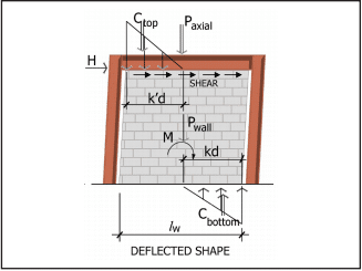
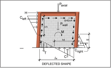
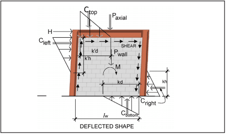
Strength design is based on the following design assumptions in conjunction with basic principles of engineering mechanics (refs. 1, 3, 5), as shown in Figure 1 for a reinforced element:
- Plane sections before bending remain plane after bending. Therefore, strain in the masonry and in reinforcement, if present, is directly proportional to the distance from the neutral axis.
- For unreinforced masonry, the flexural stresses in the masonry are assumed to be directly proportional to strain. For reinforced masonry, the tensile strength of the masonry is neglected when calculating flexural strength, but considered when calculating deflection.
- The units, mortar, grout and reinforcement for reinforced masonry act compositely to resist applied loads.
- The nominal strength of masonry cross-sections for combined flexure and axial load is based on applicable conditions of equilibrium.
- The maximum masonry compressive stress is 0.80f’m for both reinforced and unreinforced masonry.
- The maximum usable strain, εmu, at the extreme compression fiber of concrete masonry is 0.0025.
- For reinforced masonry, compression and tension stresses in the reinforcement below the specified yield strength, fy, are taken equal to the modulus of elasticity of the reinforcement, Es, times the steel strain εs. For strains greater than the yield strain corresponding to fy, stress in the reinforcement is taken equal to fy.
- For reinforced masonry, the compressive stress is rectangular and uniformly distributed over an equivalent compression zone, bounded by the compression face of the masonry with a depth of a = 0.80c.
Based on the prescribed design model outlined above, the internal distribution of stresses and strains is illustrated in Figure 1 for a reinforced masonry element. A more comprehensive review of the design model is provided in Masonry Structures, Behavior and Design (ref. 8).

2003 IBC STRENGTH DESIGN MODIFICATIONS
The 2003 IBC adopts the 2002 MSJC Code with two modifications specific to the strength design procedure in IBC Section 2108. The two modifications are as follows.
- Section 2108.2 introduces a maximum effective compression width for out-of-plane bending of six times the nominal wall thickness, not to exceed the reinforcement spacing. This is similar to limits historically used by the allowable stress design provisions in the MSJC Code as well as those adopted into the 2005 MSJC Code for strength design, as reviewed below.
- Welded and mechanical splices incorporated into masonry elements designed by the strength design method must also comply with Section 2108.3 of the 2003 IBC. For welded splices, the reinforcement to be welded must comply with ASTM A 706 (ref. 9). Splicing by mechanical connectors is classified as either Type 1 or Type 2 mechanical splices in accordance with ACI 318, Building Code Requirements for Structural Concrete (ref. 10). Type 1 mechanical splices are only required to develop 125 percent of the nominal yield strength of the reinforcement being spliced. Type 2 mechanical splices, conversely, must develop the full specified tensile strength of the reinforcement. Welded and Type 1 mechanical splices are not permitted to be used in the plastic hinge region of intermediate or special reinforced masonry shear walls.
2002 MSJC CODE STRENGTH DESIGN CRITERIA
Using strength design, the design strength of a masonry element is compared to the required (or factored) strength (indicated by the subscript u), which includes load factors to account for the uncertainty in predicting design loads and the probability of more than one design load acting simultaneously. The required strength is based on the strength design load combinations as required by Section 1605 of the IBC. At the option of the designer, or when the MSJC Code is used in conjunction with another building code that does not contain load combinations, masonry structures are designed to resist the load combination specified in ASCE 7, Minimum Design Loads for Buildings and Other Structures (ref. 11). For strength design, these load combinations are effectively the same.
The design strength of masonry is the nominal strength (indicated by the subscript n) multiplied by an appropriate strength reduction factor, Φ. The design is acceptable when the design strength equals or exceeds the factored strength (i.e., when ΦMn ≥ Mu) for all prescribed load combinations. The following sections cover the general strength design requirements applicable to both unreinforced and reinforced masonry assemblies, with the exception of design requirements for anchor bolts and lap splices. For these topics, the user is referred to TEK 12-03C, Design of Anchor Bolts Embedded in Concrete Masonry (ref. 12) and TEK 12-06A, Splices, Development and Standard Hooks for CM Based on the 2009 & 2012 IBC (ref. 13), respectively.
Strength Reduction Factors
To account for uncertainties in construction, material properties, calculated versus actual strengths and anticipated failure modes, the nominal strength of a masonry element is multiplied by an appropriate strength reduction factor, Φ. Strength reduction factors are used in conjunction with the load factors applied to the design loads. The values of the strength reduction factors for various types of loading conditions are:
- for reinforced masonry elements subjected to flexure or axial loads; Φ = 0.90;
- for unreinforced masonry elements subjected to flexure or axial loads; Φ = 0.60;
- for masonry elements subjected to shear loads; Φ = 0.80;
- for bearing on masonry elements; Φ = 0.60.
Drift and Deflection
When designing for earthquakes, the story drift (the relative displacement of adjacent stories) must be checked against the IBC prescribed allowable story drifts. When the MSJC Code is used in conjunction with a building code that does not contain allowable story drifts, the provisions of ASCE 7 are used. For masonry buildings with cantilevered shear walls, the IBC limits the story drift to 0.01hsx, where hsx is the height of the story below the level for which the drift is being calculated. For other types of masonry shear wall buildings, except masonry frames, the allowable story drift is limited to 0.007hsx. While the IBC includes story drift limits for masonry frame wall buildings, such structural configurations are rarely used. When calculating story drift, the calculated elastic deflection is multiplied by the deflection amplification factor, Cd, as prescribed in the IBC for the type of structural system being designed. The deflection amplification factor approximates the additional deflection due to inelastic response (if applicable) of the system during an earthquake. Due to the inherent in-plane stiffness of masonry assemblies, in-plane deflection and story drift are rarely a controlling limit unless a relatively large number of openings is incorporated that reduces the strength and stiffness along a line of lateral resistance.
Unlike allowable stress design, which permits deflections to be calculated assuming uncracked sections for both reinforced and unreinforced masonry, strength design requires that deflections of reinforced masonry elements be based on cracked section properties, which are limited to one-half of the gross section properties unless a rigorous cracked section analysis is performed. The deflection of unreinforced masonry elements, which are required to remain uncracked, use uncracked section properties.
Because unreinforced masonry elements must be designed to remain uncracked, deflection is rarely a controlling design limit for these systems. Reinforced masonry elements, however, particularly tall, slender walls bending in the out-of-plane direction, may exhibit excessive deflection even at relatively low applied loads. As such, the MSJC Code limits the mid-height deflection, δs, of reinforced masonry elements bending in the out-of-plane direction due to service level lateral and axial loads to 0.007h. Second order effects due to P-delta contributions must also be taken into account, which is usually accomplished through iteration until convergence is achieved.
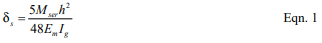
When the applied moment, Mser, is less than the moment required to cause cracking, Mcr, (Mser < Mcr) then the mid-height deflection of a masonry element subjected to a uniform out-of-plane load can be determined using Equation 1.
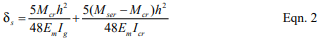
Conversely, when the applied moment, Mser, is greater than the moment required to cause cracking, Mcr, but less than the nominal moment strength of the assembly (Mcr < Mser < Mn) the mid-height deflection of a masonry element subjected to a uniform out-of-plane load can be determined using Equation 2.
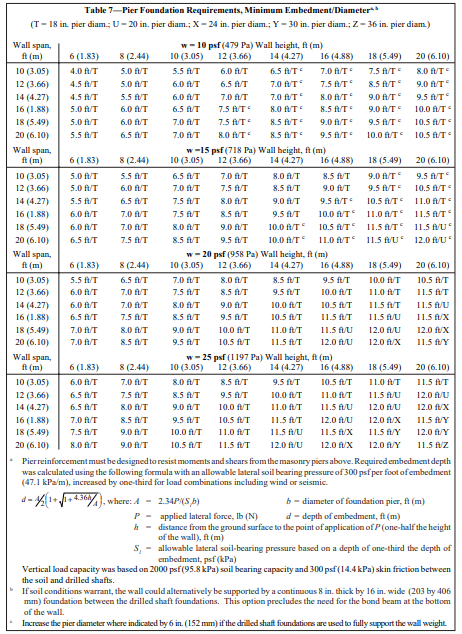
The MSJC does not prescribe a method of determining the cracked moment of inertia, Icr. As such, any rational method of determining cracked section properties is permitted. CMUTEC-002-23, Weights and Section Properties of Concrete Masonry Assemblies (ref. 14), provides typical section properties for various uncracked wall sections. For use in Equations 1 and 2, the cracking moment can be taken as:

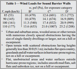
Where the modulus of rupture, fr, is obtained from Table 1 for the type of mortar and construction under consideration.
Material Properties
Due to the lack of available research data substantiating its use, the specified compressive strength of concrete masonry, f’m, designed by the strength design method is required to be at least 1,500 psi (10.34 MPa), but not larger than 4,000 psi (27.58 MPa). In addition, when used in a structural role, the specified compressive strength of grout is required to be at least equal to the specified compressive strength of concrete masonry, but not greater than 5,000 psi (34.47 MPa). For each of these upper limits on masonry assembly or grout compressive strength, the actual tested strength is permitted to exceed these values: the restriction applies only to specified strengths upon which the design is based. Note that these provisions are included in the 2005 MSJC Code as well.
Strength design of reinforced masonry is based on the specified yield strength of reinforcement, fy, which is limited to 60,000 psi (413.7 MPa). The actual yield strength of the reinforcement is limited to 1.3 times the specified yield strength. The combination of these requirements effectively precludes the use of bed joint reinforcement to be used as primary structural steel in masonry designed by the strength design method, because the nominal yield strength of bed joint reinforcement exceeds these limits. The compressive resistance of steel reinforcement is not permitted to be used unless lateral reinforcement is provided in compliance with Chapter 2 of the MSJC Code, except as permitted when checking the maximum reinforcement limits as described later.
Unreinforced Masonry
For unreinforced masonry, the masonry assembly (units, mortar and grout, if used) is designed to carry all applied stresses. The additional capacity from the inclusion of reinforcing steel, if present (such as reinforcement added to control shrinkage cracking or prescriptively required by the code), is neglected when designing unreinforced masonry elements. Because the masonry resists both tension and compression stresses resulting from applied loads, the masonry must be designed to remain uncracked.
Unreinforced Nominal Flexural Strength
The nominal flexural tensile strength of unreinforced concrete masonry is given by the modulus of rupture as prescribed in the MSJC Code, which varies with the direction of span, mortar type, bond pattern and percentage of grouting as shown in Table 1. These values apply to masonry subject to out-of-plane bending. For walls spanning horizontally between supports, the code conservatively assumes that stack bond masonry has no flexural bond strength across the mortared head joints, thus only the grout area (for horizontally grouted sections) is used. For this case, the modulus of rupture of the grout is taken equal to 250 psi (1720 kPa). Likewise, for masonry subjected to in-plane bending, the modulus of rupture normal and parallel to the bed joints is taken as 250 psi (1720 kPa).
For masonry elements subjected to a factored bending moment, Mu, and a compressive axial force, Pu, the resulting flexural bending stress is determined using Equation 4.
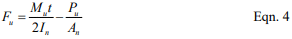
If the resulting value of Fu is positive, then the masonry section is controlled by tension and the modulus of rupture values of Table 1, reduced by the appropriate strength reduction factor (Φ = 0.60), must be satisfied. Conversely, if Fu as given by Equation 4 is negative, the masonry section is in compression and the design compressive stress of 0.80f’m applies. When using axial load to offset flexural bending stresses as described above, only dead loads or other permanent loads should be included in Pu.
Unreinforced Nominal Axial Strength
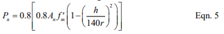
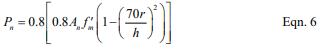
When unreinforced masonry walls are subjected to compressive axial loads only, the nominal axial compressive strength, Pn, is determined using equation 5 or 6, as appropriate. Unreinforced masonry is not permitted to carry net axial tension forces.
For elements with h/r not greater than 99:
For elements with h/r greater than 99:
Unreinforced Nominal Shear Strength
Shear stresses on unreinforced masonry elements are calculated using the net cross-sectional properties of the masonry in the direction of the applied shear force using:
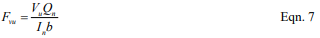
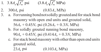
Equation 7 is applicable to determining both in-plane and out-of-plane shear stresses. Because unreinforced masonry is designed to remain uncracked, it is not necessary to perform a cracked section analysis to determine the net section properties. In turn, the applied shear stresses (factored accordingly for the appropriate load combination) are compared to the nominal shear strength, Vn, of an unreinforced masonry section, which is the least of:

Reinforced Masonry
The design of reinforced masonry in accordance with the MSJC Code neglects the tensile resistance provided by the masonry units, mortar and grout in determining the strength of the masonry assemblage. (The tensile strength of the units, mortar, and grout is considered, however, in determining the stiffness and deflection of a reinforced masonry element.) Thus, for design purposes, the portion of masonry subject to net tensile stress is assumed to have cracked, transferring all tensile forces to the reinforcement.
Using strength design, reinforcing bars used in masonry may not be larger than No. 9 (M #29) and bars may not be bundled. Further, the nominal bar diameter is not permitted to exceed one-eighth of the nominal member thickness or one-quarter of the least clear dimension of the cell, course or collar joint in which it is placed. The total area of reinforcing bars placed in a single cell or in a course of hollow unit construction may not exceed 4% of the cell area. Note that this limit does not apply at sections where lap splices occur. At lap splices, the maximum reinforcing bar area is increased to 8%, in both the 2002 and 2005 editions of the MSJC Code.
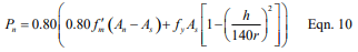
Maximum Flexural Reinforcement Ratio
To provide for a prescribed level of reinforced masonry ductility in the event of failure, the maximum reinforcement ratio, ρmax, is limited in accordance with Equation 8 or 9, as appropriate. Equation 8 applies to masonry cross sections that are fully grouted or where the neutral axis falls within the face shell of the masonry units in partially grouted construction. When the neutral axis falls within the cores of partially grouted construction, Equation 9 is used.
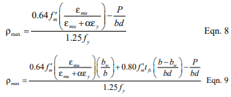
The tension reinforcement yield strain factor, α, varies with the seismic response modifi cation factor, R, masonry element, and type of loading as follows:
- α = 1.3 for walls subjected to out-of-plane forces and designed using an R value greater than 1.5,
- α = 5.0 for walls subjected to in-plane forces, for columns and for beams designed using an R > 1.5,
- α = 2.0 for masonry structures designed using an R ≤ 1.5.
In the above set of requirements, R is larger for out-of-plane loads when R is less than or equal to 1.5, which is contrary to the underlying intent of providing increased ductility for systems and elements whose ductility demand may be relatively high. Several updates and revisions to the maximum have been incorporated into subsequent editions to the 2002 MSJC Code as reviewed below.
Reinforced Nominal Axial Strength
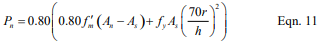
The nominal axial strength, Pu, of masonry walls, piers and columns, modified to account for the effects of slenderness, is determined using equation 10 or 11, as appropriate. The MSJC Code also limits the factored axial stress to 0.20f’m.
For elements with h/r not greater than 99:
For elements with h/r greater than 99:
Note that the reinforcing steel area, As, is included in the nominal axial strength calculation only if it is laterally confined in accordance with Chapter 2 of the MSJC Code.
Reinforced Nominal Flexural Strength
The nominal flexural strength, Mn, of a reinforced masonry element is determined as outlined below. In addition, the nominal flexural strength at any section along a member must be at least one-fourth of the maximum nominal flexural strength at the critical section.
When there are no axial loads, or when axial loads are conservatively neglected as may be appropriate in some cases, there are several circumstances to consider when determining the nominal flexural strength of reinforced masonry walls. For a fully grouted element, the internal moment arm between the resulting compressive and tensile forces is resolved to determine the resisting capacity of the section. Partially grouted walls are analyzed in the same way, but with the additional consideration of the possible influence of the ungrouted cores on the strength of the section. For partially grouted masonry bending out-of-plane, there are two types of behavior to consider.
- In the first case, when the neutral axis (the location of zero stress) lies within the compression face shell, the wall is analyzed and designed using the procedures for a fully grouted wall.
- In the second case, when the neutral axis lies within the core area, the portion of the ungrouted cells must be deducted from the area of masonry capable of carrying compression stresses.
The neutral axis location depends on the reinforcement spacing as well as the reinforcement ratio, ρ, and the distance between the reinforcement and the extreme compression fiber, d.
When analyzing partially grouted walls, it is typically initially assumed that the neutral axis lies within the compression face shell, as the analysis is more straightforward. The value of c is then calculated based on this assumption. If it is determined that the neutral axis lies outside the compression face shell, the more rigorous tee beam analysis is performed. Otherwise, the rectangular beam analysis is carried out.
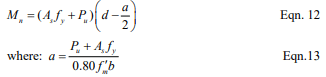
Rectangular Beam Analysis
For fully grouted masonry elements and for partially grouted masonry walls with the neutral axis in the compression face shell, the nominal flexural strength, Mn, is calculated using equations 12 and 13 as follows:
Tee Beam Analysis
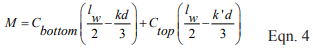
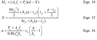
For partially grouted masonry walls where the neutral axis is located within the cores, the nominal flexural strength, Mn, is calculated using equations 14, 15, and 16 as follows:
To account for deflection resulting from out-of-plane loads and the additional bending moment due to eccentrically applied axial loads, the factored bending moment at the mid-height of a simply supported wall under uniform loading is required to be determined by Equation 17.
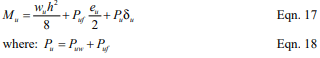
Multiple iterations may be necessary to determine the converging value of the resulting deflection.
Reinforced Nominal Shear Strength
Shear acting on reinforced masonry members is resisted by the masonry and shear reinforcement, if provided, in accordance with the following:

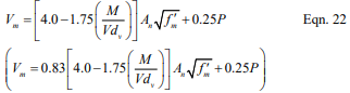
Where Vn may not exceed the values given by Equations 20 or 21, as appropriate.
Where M/Vdv is less than or equal to 0.25:

Where M/Vdv is greater than 1.00:

For values of M/Vdv between 0.25 and 1.00, the maximum value of Vn may be linearly interpolated.
The nominal shear strength provided by the masonry is determined in accordance with the following.
Where the value of M/Vdv need not be taken greater than 1.0.
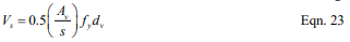
When shear reinforcement is incorporated into reinforced masonry construction, the shear strength provided by the reinforcement is calculated in accordance with the following.
2006 IBC REQUIREMENTS
The following is a brief summary of the changes and modifications adopted into the 2005 MSJC Code as referenced in the 2006 IBC. The majority of the basic design provisions remain unchanged, with several notable exceptions as reviewed below.
2006 IBC Strength Design Modifications
The same modifications for welded and mechanical splices previously discussed in the 2003 IBC Strength Design Modifications section remain in the 2006 IBC. In addition, Section 2108 of the 2006 IBC has incorporated a limit of 72db on the maximum required length of lap splices used in masonry designed by the strength design method as determined by the 2005 MSJC lap splice provisions. While this limit is typically not triggered for relatively small bar diameters, it can reduce the required lap length of large diameter reinforcing bars or in cases where small cover distances are used. Refer to TEK 12-06A (ref. 13) for detailed splice length requirements.
Other changes to Section 2108 of the 2006 IBC reflect updates and modifications to the 2005 MSJC Code to remove redundant or conflicting requirements.
2005 MSJC Code Strength Design Criteria Bearing Strength
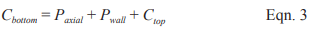
Due primarily to oversight, the 2002 MSJC Code did not include explicit provisions for determining the bearing strength of masonry subjected to concentrated loads. The bearing strength requirements adopted into the 2005 MSJC Code are similar to those used for allowable stress design, modified as necessary for use in strength design. The nominal bearing strength of masonry is taken as the greater of Equations 24 and 25:
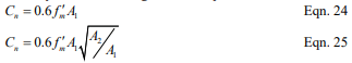
The value of 0.6 in Equations 24 and 25 is a design coefficient, not the strength reduction factor, Φ, which also happens to be equal to 0.6 for determining the design bearing strength. For use in Equation 25, the following expression must also be satisfied:

Where A1 is the actual bearing area directly under the bearing plate and A2 is the effective bearing area, defined as a right o pyramid having A1 as a top plane and sloping at 45 . For walls laid in stack bond, the area defined by A2 is terminated at head joints unless a bond beam or other means of distributing stresses is used. The concentrated stresses are distributed over a length equal to the width of the bearing area plus four times the thickness of the supporting element, but not to exceed the center-to-center distance between the concentrated loads.
Modulus of Rupture
The 2005 MSJC Code incorporated a few modifications to the modulus of rupture values presented in Table 1 for flexural tension stresses normal to the bed joints of hollow, fully grouted assemblies, as shown in Table 2. These modifications recognize that the type of mortar has less of an influence on the modulus of rupture when the element is fully grouted.
In addition, instead of prescribing a single value of 250 psi (1.72 MPa) for masonry subjected to in-plane bending as in the 2002 MSJC Code, the 2005 MSJC Code requires the use of Table 1, as modified by Table 2, for all cases of in-plane and out-of-plane bending.

Maximum Flexural Reinforcement Limits
The maximum flexural reinforcement requirements in the 2005 MSJC employ the same strain gradient approach as reviewed above, with several notable revisions.
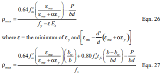
- Reinforcement is permitted to carry compression stresses, with or without lateral confining reinforcement. Further, the 1.25 factor on the nominal yield stress of the reinforcement as been removed. The resulting equations for the maximum flexural reinforcement limits are given by Equation 26 for fully grouted members or members subjected to in-plane loads, and Equation 27 for partially grouted masonry assemblies subjected to out-of-plane loads where the neutral axis falls in an open cell.
- The tension reinforcement yield strain factor, α, is taken equal to the following values when Mu/Vudv ≥ 1.0 (indicating performance is dominated by flexure):
- for intermediate reinforced masonry shear walls subjected to in-plane loads: α = 3.0,
- for special reinforced masonry shear walls subjected to in-plane loads: α = 4.0,
- for other masonry elements and loading conditions: α= 1.5.
- For cases where Mu/Vudv ≤ 1.0 (indicating shear dominated performance) and R > 1.5: α = 1.5.
- For masonry members where Mu/Vudv ≤ 1.0 and R ≤ 1.5, there is no limit on the amount of reinforcement permitted.
- The axial load, P, for use in Equations 26 and 27, is the gravity axial load component determined from the following load combination: D + 0.75L + 0.525QE.
Effective Compression Width per Reinforcing Bar
Section 2108 of the 2003 IBC included limits on the effective compression width per reinforcing bar, which were subsequently removed from the 2006 IBC, as similar provisions were incorporated into the 2005 MSJC Code. For masonry construction in running bond, and for masonry in stack bond construction with bond beams space no further than 48 in. (1,219 mm) on center, the maximum width of the compression area used is limited to the least of:
- the center-to-center spacing of the reinforcement;
- six times the nominal thickness of the element; or
- 72 in. (1,829 mm).
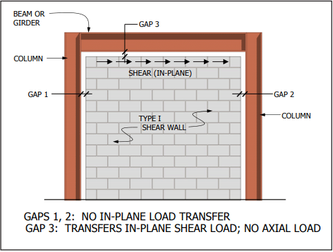
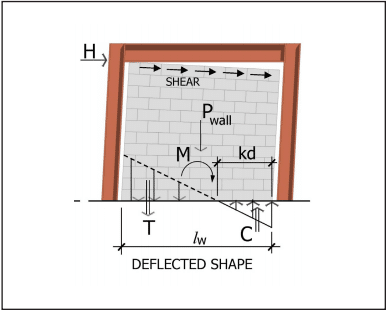
Boundary Elements
New to the 2005 MSJC Code are design provisions for boundary elements incorporated into the end zones of masonry shear walls. Because the MSJC does not include minimum prescriptive reinforcement detailing requirements for boundary elements, it requires that when used, their performance be verified by testing. In addition, when meeting the requirements for geometrical symmetry, axial load and flexural performance, the MSJC Code permits the maximum reinforcement limits as reviewed above to be waived. This exception may or may not require the incorporation of special boundary elements, depending on the design circumstances.
2008 MSJC STRENGTH DESIGN REQUIREMENTS
At the time of publication, the 2008 edition of the MSJC Code had been finalized, but the 2009 edition of the IBC had not. In anticipation of the 2009 IBC adopting the 2008 MSJC by reference, following is a brief overview of changes to the strength design provisions of the 2008 MSJC Code. In addition to some reorganization, substantive revisions to the strength design method include:
- The shear strength check to help preclude brittle failure of a masonry element during an earthquake was revised to apply only to special reinforced masonry shear walls. Previously, this check applied to both reinforced and unreinforced masonry elements regardless of seismic considerations.
- The requirement to provide at least 80 percent of the lateral stiffness through shear walls was revised to apply only to Seismic Design Categories C and higher.
- Instead of requiring that the deflection of all reinforced masonry elements be calculated on cracked section properties, the 2008 MSJC Code simply requires that the design “consider the effects of cracking and reinforcement on member stiffness,” thereby permitting more flexibility in design application.
- A moment magnifier approach was incorporated for unreinforced masonry design in determining the influence of P-delta effects. The magnified moment, Mc, is determined either through a second-order analysis, or by the following:
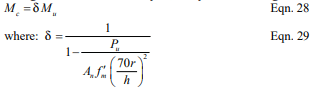
For members with h/r ≤ 45, it is permitted to take δ = 1.0. For members with 45 < h/r ≤ 60, it is permitted to take δ = 1.0 provided that the maximum factored axial stress on the element does not exceed 0.72f’m.
NOTATIONS
An = net cross-sectional area of masonry, in.² (mm²)
As = effective cross-sectional area of reinforcement, in.² (mm²)
Av = cross-sectional area of shear reinforcement, in.² (mm²)
A1 = bearing area under bearing plate, in.² (mm²)
A2 = effective bearing area, in.² (mm²)
a = depth of an equivalent compression zone at nominal strength, in. (mm)
b = width of section, in. (mm)
bw = for partially grouted walls, width of grouted cell plus each web thickness within the compression zone, in. (mm)
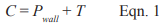
C = resultant compressive force, lb (N)
c = distance from the fiber of maximum compressive strain to the neutral axis, in. (mm)
Cd = seismic deflection amplification factor
Cn = nominal bearing strength, lb (N)
D = dead load, lb (N)
d = distance from the extreme compression fiber to centroid of tension reinforcement, in. (mm)
db = nominal diameter of reinforcement, in. (mm)
dv = actual depth of masonry in direction of shear considered, in. (mm)
d’ = distance from the extreme tension fiber to centroid of compression reinforcement, in. (mm)
Em = modulus of elasticity of masonry, psi (MPa)
Es = modulus of elasticity of reinforcement, psi (MPa)
eu = eccentricity of Puf in. (mm)
Fu = net flexural bending stress due to factored loads, psi (MPa)
Fvu = shear stress on unreinforced masonry elements, psi (MPa)
f’m = specified compressive strength of masonry, psi (MPa)
fr = modulus of rupture, psi (MPa)
fy = specified yield strength of reinforcement, psi (MPa)
h = effective height of masonry element, in. (mm)
hsx = effective height of masonry element below level x, in. (mm)
Icr = moment of inertia of cracked cross-sectional area of a member, in.4 (mm4)
Ig = moment of inertia of gross cross-sectional area of a member, in.4 (mm4)
In = moment of inertia of net cross-sectional area of a member, in.4 (mm4)
L = live load, lb (N)
M = unfactored maximum calculated bending moment at the section under consideration, in.-lb (N-mm)
Mc = factored moment magnified for the effects of member curvature, in.-lb (N-mm)
Mcr = cracking bending moment, in.-lb (N-mm)
Mn = nominal moment strength, in.-lb (N-mm)
Mser = applied bending moment, in.-lb (N-mm)
Mu = factored moment, in.-lb (N-mm)
Nv = compressive force acting normal to the shear surface, lb (N)
P = unfactored axial load, lb (N)
Pn = nominal axial strength, lb (N)
Pu = factored axial load, lb (N)
Puf = factored load from tributary floor or roof areas, lb (N)
Puw = factored weight of wall area tributary to wall section under consideration, lb (N)
QE = the effect of horizontal seismic forces, lb (N)
Qn = first moment about the neutral axis of a section of that portion of the net cross section lying between the neutral axis and extreme fiber, in.³ (mm³)
R = seismic response modification factor
r = radius of gyration, in. (mm)
Sn = section modulus of cross-section, in.³ (mm³)
s = spacing of shear reinforcement, in. (mm)
T = tension in reinforcement, lb (N)
t = specified thickness of masonry element, in. (mm)
tfs = concrete masonry face shell thickness, in. (mm)
V = unfactored shear force, lb (N)
Vm = shear strength provided by masonry, lb (N)
Vn = nominal shear strength, lb (N)
Vs = shear strength provided by shear reinforcement, lb (N)
Vu = factored shear, lb (N)
wu = out-of-plane factored uniformly distributed load, lb/in. (N/mm)
X = for partially grouted masonry, distance from extreme compression fiber to centroid of the compression resultant, in. (mm)
α = tension reinforcement yield strain factor
δ = moment magnification factor
δs = deflection due to service loads, in. (mm)
δu = deflection due to factored loads, in. (mm)
εmu = maximum usable compressive strain of masonry
εs = steel strain
εy = yield strain of reinforcement
ρ = reinforcement ratio
ρmax = maximum reinforcement ratio
Φ = strength reduction factor
REFERENCES
- Building Code Requirements for Masonry Structures, ACI 530-02/ASCE 5-02/TMS 402-02. Reported by the Masonry Standards Joint Committee, 2002.
- 2003 International Building Code. International Code Council, 2003.
- Building Code Requirements for Masonry Structures, ACI 530-05/ASCE 5-05/TMS 402-05. Reported by the Masonry Standards Joint Committee, 2005.
- 2006 International Building Code. International Code Council, 2006.
- Building Code Requirements for Masonry Structures, ACI 530-08/ASCE 5-08/TMS 402-08. Reported by the Masonry Standards Joint Committee, 2008.
- Empirical Design of Concrete Masonry Walls, TEK 1408B, Concrete Masonry & Hardscapes Association, 2008.
- ASD of Concrete Masonry (2012 IBC & 2011 MSJC), TEK 14-07C, Concrete Masonry & Hardscapes Association, 2004.
- Drysdale, R. G., Hamid, A. A. and Baker L. R., Masonry Structures, Behavior and Design, Second Edition. The Masonry Society, 1999.
- Standard Specification for Low-Alloy Steel Deformed and Plain Bars for Concrete Reinforcement, ASTM A 706/A 706M-01. ASTM International, 2001.
- Building Code Requirements for Structural Concrete, ACI 318-02. American Concrete Institute, 2002.
- Minimum Design Loads for Buildings and Other Structures, ASCE 7-02. Structural Engineering Institute of the American Society of Civil Engineers, 2002.
- Design of Anchor Bolts Embedded in Concrete Masonry, TEK 12-03C. Concrete Masonry & Hardscapes Association, 2013.
- Splices, Development and Standard Hooks for CM Based on the 2009 & 2012 IBC, TEK 12-06A, Concrete Masonry & Hardscapes Association, 2013.
- Weights and Section Properties of Concrete Masonry Assemblies, CMU-TEC-002-23, Concrete Masonry & Hardscapes Association, 2023.