Design of Reinforced Concrete Masonry Diaphragm Walls
INTRODUCTION
Masonry is a versatile and robust structural system. The available variety of materials, shapes and strengths offers countless opportunities to create many types of masonry elements. Masonry’s versatility offers a continuous spectrum of systems from unreinforced to reinforced or post-tensioned. One example of such versatility is reinforced diaphragm walls. While not specifically mentioned in Building Code Requirements for Masonry Structures (ref. 1), reinforced diaphragm walls can be designed and constructed using criteria in that standard.
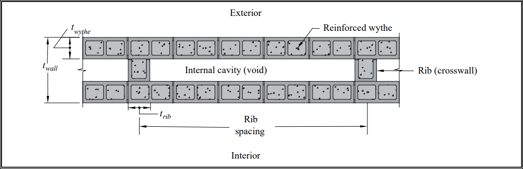
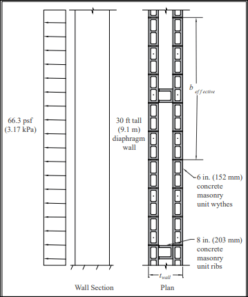
Diaphragm walls are cellular walls composed of two wythes of masonry with a large cavity or void; the wythes are bonded together with masonry ribs or crosswalls (see Figure 1). The ribs are connected to the wythes in such a way that the two wythes act compositely, thereby giving a fully composite section. This TEK covers the structural design of reinforced diaphragm walls. See TEK 03-15, Construction of Reinforced Concrete Masonry Diaphragm Walls, (ref. 2) for construction.
Figure 1 shows an example of a diaphragm wall constructed with concrete masonry units and its associated terminology. The reinforced wythes can be fully or partially grouted. The exterior face can be treated as the weathering side of the wall as shown in Figure 1, or a drainage cavity and anchored veneer can be used on the exterior face. The internal cavity (void) of the diaphragm wall is left open for utilities.
ADVANTAGES
Reinforced diaphragm walls present several opportunities for masonry design.
These include:
1. Diaphragm construction can efficiently create strong, stiff walls with individual units bonded together. Consider the economy of building a 24-in. (610-mm) thick wall with two 6 in. (152 mm) wythes and a 12 in. (305 mm) cavity rather than a solid 24 in. (610 mm) wall.
2. Thick diaphragm walls can be designed to span much further horizontally or vertically than single wythe walls or conventional composite walls. It is also possible to make very tall walls by virtue of the large sectional stiffness (ref. 3).
3. The greater thickness of diaphragm walls can also be used to replicate historic walls (buildings of Gothic style, monasteries, etc.) using modern methods.
4. The walls can have exposed, finished surfaces inside and out, and those finishes can be different because they are created by two individual wythes of masonry units.
5. The exterior wythe can be flashed and drained similar to the conventional back-up of an anchored veneer in cavity wall construction as detailed in TEK 19-05A, Flashing Details for Concrete Masonry Walls, or for single wythe walls per TEK 19-02B, Design for Dry SIngle-Wythe Concrete Masonry Walls, (refs. 4, 5).
6. The large interior voids allow for placement of insulation and utilities.
7. These walls can generate significant out-of-plane load capacity while supporting in-plane lateral loads.
8. The two distinct wythes provide a resilient system that can resist debris penetration from a high wind event and also provide great protection to potential blasts. With the high out-of-plane lateral load resistance, these walls can provide a good option for safe rooms or community rooms in tornado and hurricane regions.
HISTORICAL PERSPECTIVE
Unreinforced diaphragm walls have been used in Great Britain for decades. Many have been built using both concrete and clay masonry (Reference 3 provides wall diaphragm design criteria for concrete masonry assemblies used in Great Britain). The philosophy for unreinforced masonry in flexure is that the mortar controls the flexural tensile resistance and the composite of masonry and mortar controls both the compressive and shear stresses.
Valuable characteristics of unreinforced diaphragm walls are that the net section properties are easily calculated and they have a large moment of inertia. Given that they are thick, unreinforced diaphragm walls are effective at resisting out-of-plane loads and are inherently very stiff. However, unreinforced walls often crack before deflections control the performance. To further increase the bending resistance of unreinforced diaphragm walls, many walls in Great Britain have been posttensioned. The post-tensioning tendons are often placed in the void, unbounded and unrestrained, and protected from corrosion.
Unreinforced diaphragm walls have been used for sports halls, swimming pools, theaters, cinemas and other buildings that require tall walls. Other applications include tall freestanding walls, retaining walls, and replicating historical construction.
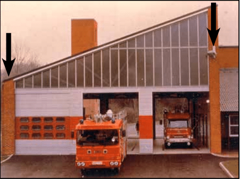
Figure 2 shows a fire station in Great Britain with posttensioned diaphragm sidewalls (arrows). These walls provide lateral stability for the building in both directions. As with traditional masonry buildings, the sidewalls are shear walls and resist loads acting on the front and rear of the building. In the transverse direction (plane of the overhead doors), the large openings leave short pier sections. Therefore, the diaphragm walls are designed to act as cantilever walls to provide the transverse building stability. This is a unique design solution because most masonry buildings do not depend upon the out-of-plane strength and stiffness of the walls to provide stability against lateral loads. Diaphragm walls, however, can be designed with sufficient thickness to develop the necessary out-of-plane strength and stiffness.
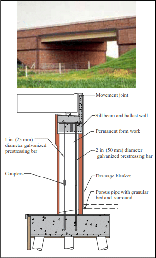
Figure 3 shows a cross-section of a bridge abutment and a photograph of the completed bridge where unreinforced post-tensioned brick diaphragm walls were used. Various bridges also use diaphragm walls for the cantilever wingwalls.
Unreinforced diaphragm walls have not been specifically addressed by name in codes and standards in the United States. Even the definition of a diaphragm wall does not exist. However, Building Code Requirements for Masonry Structures (the MSJC Code) includes design methodologies for unreinforced masonry using allowable stress design and strength design, as well as design criteria for composite assemblies. Therefore, unreinforced diaphragm walls can be designed using the existing standards, despite the fact that there is no specifically stated diaphragm wall criteria.
REINFORCED DIAPHRAGM WALLS
Even though unreinforced masonry is possible in areas of the United States, reinforced masonry is more widely adopted. Most regions require reinforcement for commercial masonry construction based upon the International Building Code (IBC) (ref. 6).
The MSJC provides design methodologies for reinforced masonry using allowable stress methods, post-tensioning, and strength design. These provisions can all be applied to reinforced concrete masonry diaphragm walls.
Design Detailing
Regardless of the design method utilized, there are some detailing criteria that apply equally to all reinforced diaphragm walls. These criteria are outlined below.
a) Spacing of Ribs
The ribs of the reinforced diaphragm wall act as webs for out-of-plane loads and connect the wythes structurally to create a composite section.
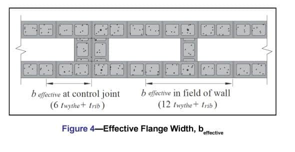
It is preferable that the ribs be spaced so that the flanges are fully effective in resisting applied loads. This is controlled by MSJC Section 5.1.1.2 which governs wall intersections. For reinforced walls where both flanges experience compression and tension, the MSJC requires the effective flange width on either side of the web to not exceed 6 times the flange thickness or 0.75 times the floor-to-floor height. In addition, the effective flange width must not extend past a control joint.
Therefore, the effective clear spacing between ribs is 12·twythe for walls without control joints (6·twythe from each rib), and the effective flange width is 12·twythe plus trib. Figure 4 illustrates how this effective flange width is smaller when a control joint is located at a rib. When placing a control joint between ribs, center the control joint and the effective flange remains 12·twythe plus trib.
b) Flange Thickness
The masonry unit selected for the flange wythe dictates the flange thickness (twythe). To accommodate reinforcement, a 6-in. (152-mm) concrete masonry unit is the smallest practical unit to be used. Larger units can be used to accommodate larger bars and provide larger compression areas.
c) Grouting
The choice of full vs. partial grouting is a function of design:
1. If the compression area required by out-of-plane
design exceeds the face shell thickness of the wythe,
the recommendation is to fully grout the flanges. Alternatively, the designer can use partial grouting and perform a T-beam analysis on the wall.
2. If the compression area does not exceed the face
shell thickness of the wythe, either partial or full
grouting can be used without using the more cumbersome T-beam analysis.
3. The ribs are often fully grouted, but they can also
be designed with partial grouting.
d) Masonry Bond
TMS 402 Section 5.1.1.2.1 requires that intersecting walls be constructed in running bond for composite flanging action to occur. Therefore, reinforced diaphragm walls are always constructed in running bond.
e) Connecting the Ribs to the Wythes
MSJC Section 5.1.1.2.5 requires that the connection of intersecting walls conform to one of the following requirements:
1. At least fifty percent of the masonry units at the interface
must interlock.
2. Walls must be anchored by steel connectors grouted into
the wall and meeting the following requirements:
(a) Minimum size: 1/4 in. x 1-1/2 in. x 28 in. (6.4 x 38.1 x711 mm) including a 2-in. (50.8-mm) long, 90-degree bend at each end to form a U or Z shape.
(b) Maximum spacing: 48 in. (1,219 mm).
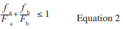
3. Intersecting reinforced bond beams must be provided at a maximum spacing of 48 in. (1,219 mm) on center. The minimum area of reinforcement in each bond beam is 0.1 in.2 per ft (211 mm2/m) multiplied by the vertical spacing of the bond beams in feet (meters). Reinforcement is required to be developed on each side of the intersection.
The use of bond beams in requirement 3 above is one
way of handling the interface shear requirement. However,
the equations below can also be used for this purpose:
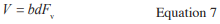
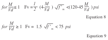
For allowable stress design:
fv = V/An TMS 402 Section 8.3.5.1.1 (Eqn. 8-21)
where Fv is controlled by Section 8.3.5.1.2.
For strength design, the shear strength, fv, is controlled by
Sections 8.3.5.1.2 and 8.3.5.1.4.
f) Control (Movement) Joints
CMU-TEC-009-23, Crack Control Strategies for Concrete Masonry Construction (ref. 7) are the industry standards for determining control joint spacing. Both were developed for single wythe walls with and without horizontal reinforcement.
There is no specific research on shrinkage characteristics of reinforced diaphragm walls. The expectation is that the ribs restrain shrinkage movement of the wythes and the resulting spacing of control joints can be increased over what would be expected for a single wythe wall. Until research becomes available, however, the current recommendation is to use the existing industry crack control recommendations to space control joints for reinforced diaphragm walls.
Additional attention must be placed on the size of the corner control joints if the diaphragm walls are used to support out-ofplane loads (see Example 1).
Allowable Stress Design of Reinforced Diaphragm Walls
Reinforced masonry designed using allowable stress design (ASD) methods follows similar guidelines as that used for unreinforced masonry. The maximum wall height is controlled by the loadings and slenderness effects. The slenderness effects are based upon the h/r ratio and prevent the wall from buckling.
The design methodology for reinforced diaphragm walls is similar to reinforced single wythe wall design and is discussed in TEK 14-07C, ASD of Concrete Masonry (2012 IBC & 2011 MSJC) (ref. 8).
Strength Design of Reinforced Diaphragm Walls
The strength design method has no specific limit on h/t. However, it has design criteria that limit service load deflections and ultimate moment capacity for out-of-plane loads. The service load deflections cannot exceed 0.7 percent of the wall height. For a 30-ft (9.1 m) wall, that is 2.5 in. over 30 ft (64 mm over 9.1 m) for a simply supported wall.
There is an axial load capacity limitation when h/t exceeds 30: the factored axial load for these walls must be limited to 5 percent of f’m based upon the gross section properties.
The design methodology is similar to single wythe design and is discussed in CMHA TEK 14-11B, Strength Design of CM Walls for Axial Load & Flexure (ref. 9)
Reinforced Concrete Masonry Diaphragm Walls Using Post-tensioned Masonry Design
Post-tensioned masonry design of diaphragm walls is the same as single wythe design. However, the large void in diaphragm walls provides an opportunity for the tendons to be placed eccentrically as needed for the loadings. Placed inside the void, the tendons are generally unbonded and unrestrained.
Seismic Design
The MSJC Code and ASCE 7 (refs. 1, 11) provide additional criteria for seismic design of walls that need to be considered as for any other masonry wall. This includes the degree of grouting and the inclusion of prescriptive reinforcement.
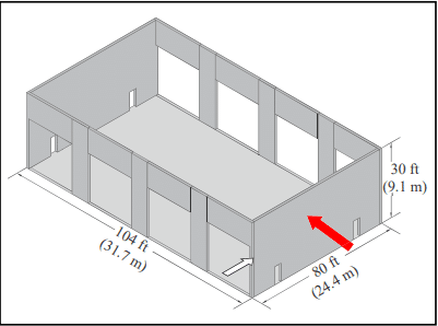
DESIGN EXAMPLE: WINGWALL DESIGN FOR A REINFORCED CONCRETE MASONRY MAINTENANCE STORAGE FACILITY
Figure 5 shows the basic building layout for the design example. The front and rear walls are perforated with 20 ft x 20 ft (6.1 x 6.1 m) overhead doors for vehicle access. Control joints are shown over the door openings; the pier sections are 6 ft (1.8 m) in length. The endwalls have personnel access openings. Because the front and rear walls are perforated, the pier sections may not have sufficient in-plane stiffness and strength. Therefore, the endwalls should be designed to brace the building in both directions.
Although the roof structure is not shown, long-span joists bear on the front and rear sidewalls (i.e., the walls with the large perforations); the endwalls are nonloadbearing. The roof diaphragm would be designed to distribute the frontrear lateral loads to the endwalls, which must be designed as conventional shear walls. Conventional shear wall design is covered by the Masonry Designer’s Guide (ref. 12) and is not covered here.
The roof diaphragm will not be used to brace the side-toside lateral forces. For this example, the out-of-plane design (the large red arrow in Figure 5 depicts the out-of-plane load) will treat the endwalls as diaphragm walls acting as cantilevers to brace the building for the side-to-side lateral loads similar to Figure 2. This decision exempts the roof diaphragm from the strength and stiffness requirements for lateral loads that are perpendicular to the plane of the roof trusses. These requirements are typically met by horizontal braces between roof trusses.
Input:
Location: Coastal US, South Carolina
Loadings: ASCE 7-16, Part 2 for wind design
Masonry Standard: TMS 402, ASD method Because no bracing is used at the top of the wall, component and cladding loads will be used to design the wall.
1. Proposed wall section
Use 6-in. (152-mm) concrete masonry units for wythes and 8-in. (203-mm) for ribs (see Figure 1).
Masonry units: ASTM C90 (ref. 12), f’m = 2,000 psi (13.8 MPa); unit weight 125 pcf (2,000 kg/m3)
Reinforcement: ASTM A615 (ref. 13), Grade 60
Grout: ASTM C476 (ref. 14), 2,000 psi (13.8 MPa)
Mortar: ASTM C270 (ref. 15), Type S
2. Select control joint spacing
The three possible options are:
a) Using CMU-TEC-009-23 (empirical method), space control joints at the lesser of 1.5h = 45 ft (13.7 m), max 25 ft (7.62 m). The 25 ft (7.62 m) criteria governs. The required horizontal reinforcement in the walls is 0.025 in.2/ft (CMUTEC-009-23, Table 1). This corresponds to two-wire W1.7 TEK 14-24 5 CONCRETE MASONRY & HARDSCAPES ASSOCIATION masonryandhardscapes.org (9 gauge, MW11) joint reinforcement at 16 in. (406 mm) on center vertically over the height of the wall (CMUTEC-009-23, Table 2).
b) Using CMU-TEC-009-23 (alternative engineered method), space control joints at the lesser of 2.5h = 75 ft or 25 ft (7.62 m). Again, the 25 ft (7.62 m) criteria governs. The required horizontal reinforcement in the walls is 0.0007An , which corresponds to 0.064 in2/ft or two-wire W1.7 (9 gauge, MW11) wire joint reinforcement at 24 in. (610 mm) on center vertically over the height of the wall (CMUTEC-009-23, Table 5).
c) Using CMU-TEC-009-23, space control joints at any length provided the horizontal reinforcement in the walls exceeds 0.002An (CMU-TEC-009-23). This corresponds to 0.183 in2/ft or two No. 6 (M#19) reinforcing bars in bond beams at 32 in. (813 mm) on center vertically over the height of the wall (CMU-TEC-009-23, Table 6 for fully grouted walls).
To minimize the possible number of control joints, select option c) with the horizontal bond beams. Provide control joints only at the corners (Figure 5). If the designer chooses to use horizontal joint reinforcement and not bond beams, the maximum control joint spacing would be 25 ft (7.62 m) using either options a) or b).
While the inner wythe will generally be exposed principally to shrinkage with only minor thermal effects, it is common to reinforce both wythes similarly.
3. Determine wind loads
From ASCE 7-16 Part 2, the suction load at the Exterior Zone (5) is calculated as 66.3 psf (3.17 kPa) (see Figure 6). In ASCE 7, wind loads are strength level. Roof dead load is ignored at the nonbearing wall.
4. Determine base of wall loads
Vu = 66.3 psf × 30 = 1,989 lb/ft of wall (29.0 kN/m)
Mu = 66.3 x (30)2/2= 29,835 ft-lb/ft of wall (132 kN-m/m)
Vser = 0.6 Vu = 1,193 lb/ft of wall (17.4 kN/m)
Mser = 0.6 Mu = 17,901 ft-lb/ft of wall (79.6 kN-m/m)
Note: 0.6 reduces Vu to ASD per ASCE 7.
5. Determine beffective
in field of wall (solid region away from openings):
beffective = 12twythe + trib = 12(6 in.) + 8 in. = 80 in. (2,032 mm)
6. Determine minimum twall to satisfy shear capacity
Vrib = Vser × 80/12 = 7,953 lb (35.4 kN)
fv = Vrib/Arib = 7,953/[(7.63 in.)·twall] (TMS 402, Equation 8-21)
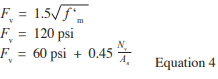
Fv ≤ 2 √f’m γg = 89 psi, assuming M/Vd > 1.0 and γg = 1.0 (MSJC Code, Equation 8-24)
This produces twall ≥ 11.7 in. (297 mm)
Checking M/Vd = 17,901/[1,193 x (<1 ft)] = 15.0 > 1.0 OK
Shear is not an issue. The prescriptive requirements for the
intersection of the ribs and flanges are sufficient.
7.Determine minimum twall due to moment capacity
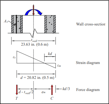
Try a rib length of 1.5 courses of concrete masonry.
twall = 15.625 in. unit + 0.375 in. mortar joint + 7.625 in. half
unit = 23.63 in. (600 mm)
d = 23.63 in. – (5.63 in./2) = 20.82 in. (529 mm)
Ignoring axial load,
As (estimated) = Mser /(2.16d)
= (17,901/1,000)(2.16 x 20.82 in)(529 Mm)
Try No. 8 at 24 in. o.c. (As = 0.40 in.2/ft) (M#25 at 610 mm o.c.)
8. Determine wall dead load at base of wall
From CMU-TEC-002-23 (ref. 16): wall weight of 125 pcf 6 in. fully grouted concrete masonry = 62 psf (303 kg/m2 )
125 pcf 8 in. fully grouted = 84 psf (411 kg/m2 )
Flange load: 2 wythes x 62 psf = 124 psf per ft
Rib load: [23.63 in. – 2(5.63 in.)]/12 x 84 psf/80 in./12 = 13.0 psf/ft of wall
PDL = (124 + 13.0) x 30 ft = 4,110 lb/ft of wall (60 kN/m)
9. Load combination
0.6 PDL + 0.6W from ASCE 7-10 for ASD
Note: This one load combination is shown for this example. The designer must check all combinations required by ASCE 7.
P = 0.6PDL = 0.6 (4,110) = 2,466 lb/ft (36 kN/m)
M = 0.6 Mu, wind = Mser = 17,901 ft-lb/ft (79.6 kN-m/m)
10. Determine n
From MSJC Section 4.2.2:
Es = 29,000,000 psi (200,000 MPa)
Em = 900f’m = 1,800,000 psi (12,410 MPa) n = Es/Em = 16.1
For As = 0. 44 in.2 /ft (from 7 above),
nρ = nAs /bd = 16.1(0.4)/12(20.82) = 0.026
If P = 0, k = √ (nρ)2 + 2nρ – nρ = 0.204;
j = 1- (k/3) = 0.932
kd = 4.25 > tface of 6-in. CMU but less than the wythe thickness. Axial load may increase kd. Therefore, grouting the full
wythe is appropriate.
11. Design for PDL and M
(see Figure 7)
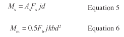
From statics: P = C – T
M = C x em + T (d – twall/2)
Per foot: C = 1/2(kd)fm x 12 in.
fm = Em εm
T = As fs
fs = Es εs
em = twall/2 – kd/3
From strain compatibility: εm/kd = εs(d – kd)
(fm /Em)/kd = (fs/Es)/(d – kd) → fs = n [(d – kd)/kd] fm
Therefore, C = 6(kd)fm
T = 0.4(16.1)((20.82 – kd)/kd)) fb
= 6.44((20.82 – kd)/(kd)) fb
Solving for P = C – T and M = C em + T (d – twall/2)
gives kd = 4.65 in. (118 mm) and fb = 498 psi (3.4 MPa)
Checking:
C = 12,449 lb (55 kN)
T = 10,030 lb (44 kN)
P = 2,419 lb (10.7 kN) OK
em = twall/2 – kd/3 = 10.27 in. (264 mm)
M = C em + T (d – twall/2)
= 12,449(10.27)/12 + 10,030(20.82 – 23.63/2)/12
= 18,185 ft-lb approx. = M =17,901 ft-lb OK
Check:
fm = 498 psi < Fb = 0.45 f’m = 900 psi (6.2 MPa)
OK (TMS 402 8.3.4.2.2)
fs = 16.1((20.82 – 4.86)/4.86) 417 psi = 22,047 psi (152 MPa)
fs < Fs = 32,000 psi (221 MPa) OK (MSJC 8.3.3.1)
MSJC Section 8.3.4.2.2 requires an additional check for fa alone. The design engineer is generally advised to perform this check. However, it rarely controls for diaphragm walls due to the stiff wall section. For this example, there is no applied axial load so the check is not required.
Therefore, this section checks using No. 8 bars at 24 in. on center (M#25 at 610 mm) in a fully grouted diaphragm wall. Note that this only applies to the end zone in suction. The design calculations should be repeated:
a. for pressure load on the end zone,
b. for pressure and suction over the interior zone,
c. over the height of the wall to reduce the amount of vertical reinforcement, and
d. the design should be checked adjacent to control joints and openings.
Using the walls to support of out-of-plane loads requires the foundations to be designed and detailed for the cantilever walls.
12. Check deflection at top of the wall for a cantilever
Using loads and section properties for beffective.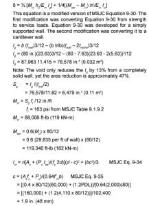
Provide the control joints between the sidewalls and the front/ rear walls. Construct with sealant that has a shear capacity of 50% of the joint thickness, the joint thickness should exceed 2 x 0.56 in. = 1.12 in. (28 mm). See white arrow on Figure 5.
SUMMARY
Reinforced concrete masonry diaphragm walls provide opportunities for engineers to design a) very tall walls and b) brace walls using the diaphragm walls as cantilevers. For buildings, these are two unique options that are not normally available from traditional masonry walls.
NOTATIONS
An = net cross-sectional area of a member, in.2 (mm2)
As = area of nonprestressed longitudinal tension reinforcement, in.2(mm2)
b = width of section, in. (mm)
beffective = effective width of section, in. (mm)
C = resultant compressive force, lb (N)
c = distance from the fiber of maximum compressive
strain to the neutral axis, in. (mm)
d = distance from extreme compression fiber to centroid of tension reinforcement, in. (mm)
Em = modulus of elasticity of masonry in compression, psi (MPa)
Es = modulus of elasticity of steel, psi (MPa)
em = eccentricity of axial load, in. (mm)
Fm = allowable compressive stress, psi (MPa)
fm = calculated compressive stress in masonry due to axial and flexure, psi (MPa)
Fv = allowable shear stress, psi (MPa)
Fs = allowable tensile or compressive stress in reinforcement, psi (MPa)
fa = calculated compressive stress in masonry due to axial load only, psi (MPa)
f’m = specified compressive strength of clay masonry or concrete masonry, psi (MPa)
fr = modulus of rupture, psi (MPa)
fs = calculated tensile or compressive stress in reinforcement, psi (MPa)
fv = calculated shear stress in masonry, psi (MPa)
fy = specified yield strength of steel for reinforcement and anchors, psi (MPa)
h = effective height of wall, in. (mm)
Icr = moment of inertia of cracked cross-sectional area of a member, in 4 (mm4)
Ig = moment of inertia of gross cross-sectional area of a member,, in.4 (mm4)
j = ratio of distance between centroid of flexural compressive forces and centroid of tensile forces to
depth, d
k = ratio of the distance between the compression face of an element and the neutral axis to the effective depth d
M = maximum moment at the section under consideration, in.-lb (N-mm)
Mcr = nominal cracking moment strength, in.-lb (N-mm)
Mser = service moment at midheight of a member, in.-lb (N-mm)
Mu = factored moment, magnified by second-order effects where required by the code, in.-lb (N-mm)
n = modular ratio, Es/Em
P = axial load, lb (N)
PDL = axial load due to dead load, lb (N)
Pu = factored axial load, lb (N)
r = radius of gyration, in. (mm)
Sg = section modulus of the gross cross-sectional area
of a member, in.3(mm3)
T = resultant tensile force, lb (N)
t = nominal thickness of member, in. (mm)
tface = specified thickness of masonry unit faceshell, in. (mm)
trib = specified thickness of diaphragm wall rib, in. (mm)
tsp = specified thickness of member, in. (mm)
twall = specified thickness of wall, in. (mm)
twythe = specified thickness of the masonry wythe, in. (mm)
V = shear force, lb (N)
Vrib = shear capacity (resisting shear) of diaphragm wall rib, lb (N)
Vser = service level shear force, lb (N)
Vu = factored shear force, lb (N)
W = wind load, psf (kPa)
γg = grouted shear wall factor
δ = moment magnification factor
εm = compressive strain of masonry
εs = strain of steel
f = strength reduction factor
ρ = reinforcement ratio
References
- Building Code Requirements for Masonry Structures, TMS 402-16, Reported by The Masonry Society 2016.
- Construction of Reinforced Concrete Masonry Diaphragm Walls, TEK 03-15, Concrete Masonry & Hardscapes Association, 2017.
- Aggregate Concrete Blocks: Unreinforced Masonry Diaphragm Walls, Data Sheet 10. Concrete Block Association of Great
Britain, March 2003. - Flashing Details for Concrete Masonry Walls, TEK 19-05A, Concrete Masonry & Hardscapes Association, 2008.
- Design for Dry Single-Wythe Concrete Masonry Walls, TEK 19-02B, Concrete Masonry & Hardscapes Association, 2012.
- International Building Code. International Code Council, 2015/2018.
- Crack Control Strategies for Concrete Masonry Construction, CMU-TEC-009-23, Concrete Masonry & Hardscapes Association, 2023.
- TEK 14-07C, ASD of Concrete Masonry (2012 IBC & 2011 MSJC). Concrete Masonry & Hardscapes Association, 2013.
- TEK 14-11B, Strength Design of CM Walls for Axial Load & Flexure. Concrete Masonry & Hardscapes Association, 2003.
- Minimum Design Loads for Buildings and Other Structures, ASCE/SEI 7-10. American Society of Civil Engineers, 2010.
- Masonry Designers’ Guide, Seventh Edition, MDG-7. The Masonry Society, 2013.
- Standard Specification for Loadbearing Concrete Masonry Units, ASTM C90-14. ASTM International, Inc., 2014.
- Standard Specification for Deformed and Plain CarbonSteel Bars for Concrete Reinforcement, ASTM A615/ A615M-14. ASTM International, Inc., 2014.
- Standard Specification for Grout for Masonry, ASTM C476-10. ASTM International, Inc., 2010.
- Standard Specification for Mortar for Unit Masonry ASTM C270-14. ASTM International, Inc., 2014.
- Weights and Section Properties of Concrete Masonry Assemblies, CMU-TEC-002-23.Concrete Masonry & Hardscapes Association, 2023.