Concrete Masonry Gravity Retaining Walls
INTRODUCTION
Retaining walls support soil and other materials laterally. That is, retaining walls “retain” earth, keeping it from sliding. Retaining walls must resist overturning and sliding, and the pressure under the toe (front bottom edge of footing) should not exceed the bearing capacity of the soil. Finally, the wall must be strong enough to prevent failure at any point in its height due to the pressure of the retained material. Concrete masonry retaining walls meet these requirements admirably.
Three different types of concrete masonry retaining walls are illustrated in Figure 1. They are the simple unreinforced vertical face gravity retaining wall, the steel reinforced cantilever retaining wall, and the segmental retaining wall. This TEK addresses unreinforced gravity retaining walls only. Each of these retaining wall systems has its advantages, and the choice may depend on a number of factors including aesthetics, constructibility, cost, and suitability for a particular project. The gravity wall is much simpler in design and construction, and can be an effective choice for smaller projects. It is thicker at the base than cantilever and segmental walls, and hence could cost more to construct on larger projects. Gravity retaining walls resist sliding by means of their large mass, whereas cantilever retaining walls are designed to resist sliding by using reinforcement. Because of their large mass, gravity retaining walls may not be appropriate for use on soils with low bearing capacities.
An engineer who is familiar with local conditions can assist in the choice of retain ing wall type. Where especially unfavorable soil conditions occur or where piling is required under a retaining wall, the assistance of an engineer is essential for design and construction.

DESIGN
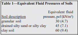
The primary force acting on a retaining wall is the pressure exerted by the retained material at the back of the wall and on the heel of the footing. The magnitude and direction of this pressure depends on the height and shape of the surface and on the nature and properties of the backfill. One common method of estimating backfill pressure is the equivalent fluid pressure method. In this method, it is assumed that the retained earth will act as a fluid in exerting pressure on the wall. Assumed equivalent fluid pressures vary with the type of soil. Representative soil types with their equivalent fluid pressures are shown in Table 1.
Since the stability of the gravity type retaining wall depends mainly on its weight, the thickness required at its base will increase with height of backfill, or wall height. Uplift pressure at the back of the wall (the heel) is avoided by designing the gravity retaining wall thick enough at the base so that the resultant of all forces (overturning force and vertical loads) falls within a zone called the kern, which is the middle one third of the base. The eccentricity of the resultant force is equal to or less than one-sixth of the base width. When the eccentricity, e, is equal to one-sixth the base width exactly, the maximum footing pressure on the soil at the front edge of the base (toe) will be twice the average pressure on the soil.
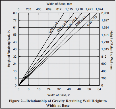
The horizontal force of the retained material causes the overturning moment on the gravity retaining wall. For a given wall height, the required thickness at the base will depend not only on height, but also on the magnitude of the equivalent fluid pressure of the retained soil. The two forces act in opposition; the horizontal force tends to overturn the wall, while the vertical forces tend to stabilize it via gravity. The ratio of wall height to base width will vary with the ratio of vertical pressure to horizontal pressure. More properly, the relationship between thickness of base and wall height can be expressed:

where:
H = height of gravity retaining wall, in. (mm)
L = width of gravity retaining wall at base, in. (mm)
Q = equivalent fluid pressure of retained material acting horizontally as overturning moment, pcf (kg/m³)
W = average weight of masonry, soil and other material acting vertically to retain soil, pcf (kg/m³)
This relationship between wall height and base width for gravity retaining walls is shown in Figure 2 for different ratios of horizontal to vertical unit loads. The relationship shown in Figure 2 is employed in the selection of dimensions for gravity retaining walls up to eight ft (1.8 to 2.4 m) high.
Having selected the height-base proportions from Figure 2, the trial design is analyzed for safety against overturning and sliding, bearing pressure on the soil, and flexural and shear stress in the wall.
CONSTRUCTION AND MATERIALS
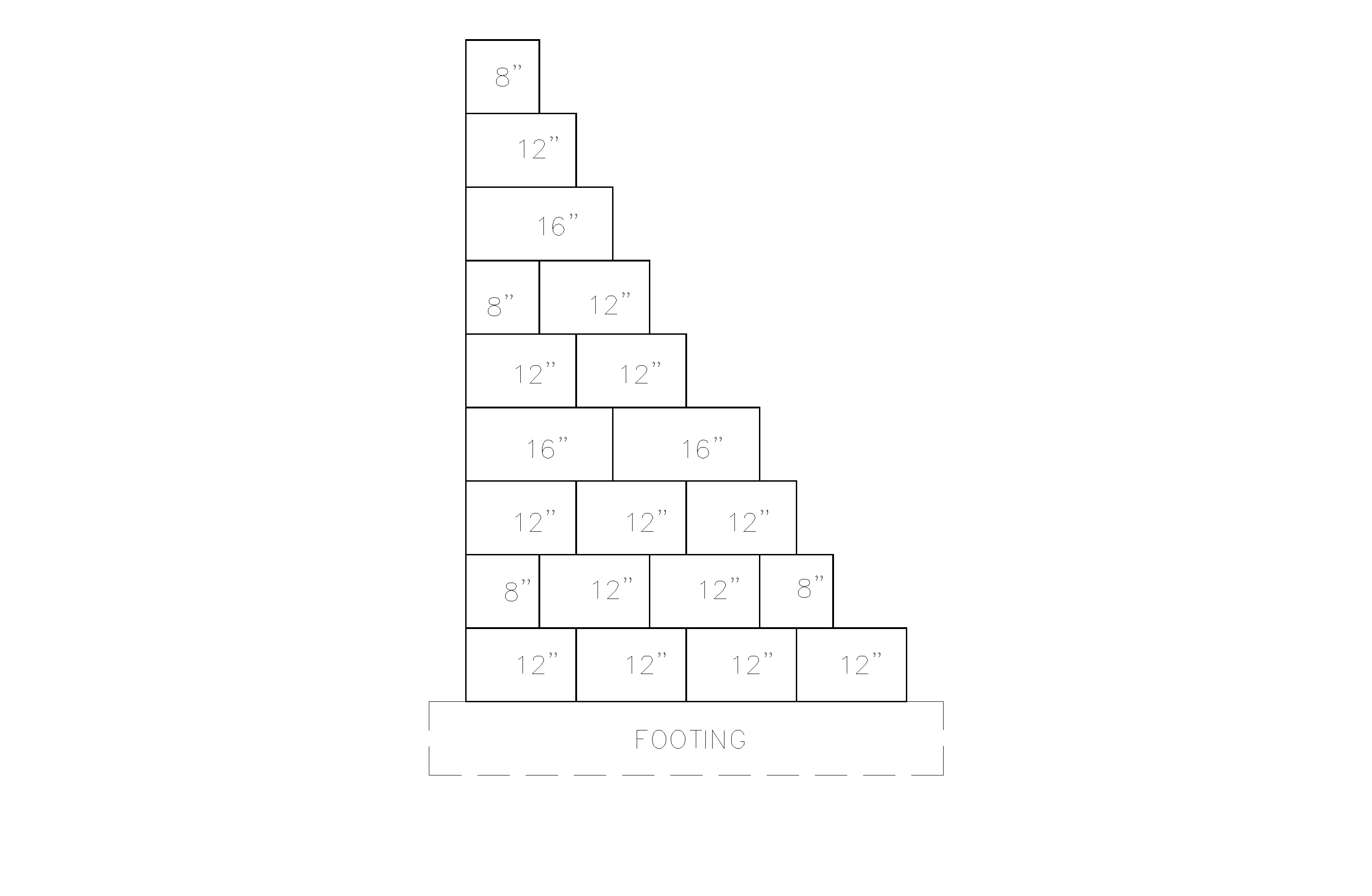
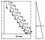
Each course of the retaining wall should be constructed with full-size concrete masonry units, with an overlapping bond pattern between courses, as shown in Figure 3.
Hollow or solid concrete masonry units used in gravity retaining walls should meet the requirements of ASTM C 90 (ref. 2) and preferably have an oven-dry density of 125 lb/ft³ (2002 kg/m³) or more. Cores of hollow units are typically filled to increase the weight of the wall. The fill should be granular in areas subject to freezing. Bond is important to ensure sufficient shear resistance to withstand the pressure exerted by the retained earth. Type M or S mortars complying to ASTM C 270 (ref. 3) are recommended.
Concrete footings should be placed on firm undisturbed soil. In areas where freezing is expected, the base of the footing should be placed below the frost line. If the soil under the footing consists of soft or silty clay, it is usually advisable to place 4 to 6 in. (102 to 152 mm) of well compacted sand or gravel under the footing before pouring the concrete. It is usually not necessary to reinforce the footing.
If heavy equipment is employed for backfilling, it should not be allowed to approach closer to the top of the wall than a distance equal to the wall height. Care should also be taken to avoid large impact forces on the wall as could occur by a large mass of moving earth.
Provision should be made to pre vent water accumulation behind the retaining wall. Accumulated water causes increased pressure, seep age, and in areas subject to frost action, an expansive force of considerable magnitude near the top of the wall. In most instances, weep holes located at 5 to 10 foot (1.5 to 3 m) spacing along the base of the wall are sufficient.
DESIGN EXAMPLES
- 4-foot (1.2 m) high gravity retaining wall
equivalent fluid pressure of soil = 30 pcf (4.7 kN/m³)
soil weight = 100 pcf (15.7 kN/m³)
soil friction coefficient = 0.55
soil bearing capacity = 2000 lb/ft² (0.096 MPa)
100% solid concrete masonry units, 120 pcf (18.9 kN/m³)
concrete footing, 150 pcf (23.6 kN/m³)
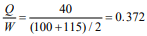
First, determine the width of the wall base:
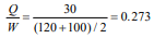
From Figure 2, the base of the wall is 24 in. (610 mm), which can be accomplished using three 8-inch (203 mm) block. Note that the footing weight was not included in the calculation of average unit weight of the materials acting vertically, so that the width determined from Figure 2 would be the width of the masonry wall at its base.
Determine overturning moment:
pressure at the base of the wall, p = total soil height x equivalent fluid pressure of soil
p = (4.67 ft)(30 pcf) = 140 lb/ft² (6703 Pa)
resultant pressure, P = ½ (p)(total soil height)
P = ½ (140 lb/ft²)(4.67 ft) = 327 lb/ft (4.8 kN/m)
Determine resisting moment (about the toe):
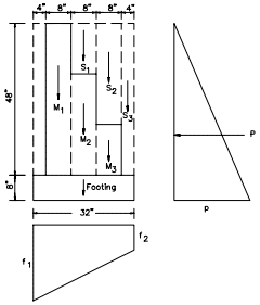
First, determine the weight of each element, then determine the resisting moment of each weight, then sum the resisting moments to determine the total resisting moment.
| Element: | Weight | |
| S1 | (0.67 ft)(1.33 ft)(100 pcf) | = 89 lb (396 N) |
| S2 | (0.67 ft)(2.67 ft)(100 pcf) | = 179 lb (796 N) |
| S3 | (0.33 ft)(4.0 ft)(100 pcf) | = 132 lb (587 N) |
| M1 | (0.67 ft)(4.0 ft)(120 pcf) | = 322 lb (1432 N) |
| M2 | (0.67 ft)(2.67 ft)(120 pcf) | = 214 lb (952 N) |
| M3 | (0.67 ft)(1.33 ft)(120 pcf) | = 107 lb (476 N) |
| F | (2.67 ft)(0.67 ft)(150 pcf) | = 268 lb (1192 N) |
| Element: | Weight, lb (N) x | Arm, ft (m) = | Moment, ft-lb (N-m) |
| S1 | 89 (396) | 1.33 (0.41) | 118.5 (161) |
| S2 | 179 (796) | 2.00 (0.61) | 357.8 (485) |
| S3 | 132 (587) | 2.50 (0.76) | 330.0 (447) |
| M1 | 322 (1432) | 0.67 (0.20) | 215.5 (292) |
| M2 | 214 (952) | 1.33 (0.41) | 285.5 (387) |
| M3 | 107 (476) | 2.00 (0.61) | 213.9 (290) |
| F | 268 (1192) | 1.33 (0.41) | 356.4 (483) |
| Total | 1311 (5832) | 1878 (2546) |
Determine the overturning moment about the base, M:
M = (P)(⅓ x total height of soil)
M = (327 lb/ft)(⅓ x 4.67 ft) = 509 ft-lb/ft (2.28 kN-m/m)
Check safety factors:
overturning moment safety factor = 1878/509 = 3.7
3.7 > 2 OK
sliding safety factor = (1311 lb)(0.55)/(327 lb/ft) = 2.2
2.2 > 1.5 OK
Check pressure on soil:
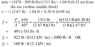
Since the concrete masonry used in this example is assumed solid or fully grouted, the calculations do not include a check of shear stresses and flexural stresses in the wall. Flexural and shear stresses are checked in the second design example, and it is seen that the magnitudes are very low. Flexural and shear stresses in gravity retaining walls will almost always be of minor importance.
- 6-foot (1.8 m) high gravity retaining wall
equivalent fluid pressure of soil = 40 pcf (7.1 kN/m³)
soil weight = 100 pcf (15.7 kN/m³)
soil friction coefficient = 0.55
soil bearing capacity = 2000 lb/ft² (0.096 MPa)
hollow concrete masonry units, 130 pcf (20.4 kN/m³), units will be filled with sand, resulting in a combined weight of 115 pcf (18.1 kN/m³)
f’m = 1500 psi (10.3 MPa)
Type S portland cement-lime mortar concrete footing, 150 pcf (23.6 kN/m³)
First, determine the width of the wall base:
From Figure 2, try a base width of 42 in. (1067 mm), with a footing width of 50 in. (1270 mm)
Determine overturning moment:
p = (6.67 ft)(40 pcf) = 267 lb/ft² (0.013 MPa)
P = ½ (267 lb/ft²)(6.67 ft) = 890 lb/ft (13 kN/m)
M = (890 lb/ft)(⅓ x 6.67 ft) = 1978 ft-lb/ft (8.81 kN-m/m)
| Element: | Weight, lb (N) x | Arm, ft (m) = | Moment, ft-lb (N-m) |
| S1 | 22 (98) | 1.50 (0.46) | 33 (45) |
| S2 | 44 (196) | 1.83 (0.56) | 80 (108) |
| S3 | 66 (294) | 2.17 (0.66) | 143 (194) |
| S4 | 88 (391) | 2.50 (0.76) | 220 (298) |
| S5 | 110 (489) | 2.83 (0.86) | 311 (422) |
| S6 | 132 (587) | 3.17 (0.97) | 418 (566) |
| S7 | 154 (685) | 3.50 (1.07) | 539 (731) |
| S8 | 176 (783) | 3.83 (1.17) | 674 (914) |
| S9 | 198 (881) | 4.17 (1.27) | 826 (1120) |
| M1 | 690 (3070) | 0.83 (0.25) | 575 (780) |
| M2 | 202 (899) | 1.50 (0.46) | 303 (411) |
| M3 | 177 (787) | 1.83 (0.56) | 325 (441) |
| M4 | 152 (676) | 2.17 (0.66) | 329 (446) |
| M5 | 126 (560) | 2.50 (0.76) | 316 (428) |
| M6 | 101 (449) | 2.83 (0.86) | 287 (389) |
| M7 | 76 (338) | 3.17 (0.97) | 241 (327) |
| M8 | 50 (222) | 3.50 (1.07) | 177 (240) |
| M9 | 25 (111) | 3.83 (1.17) | 97 (132) |
| F | 419 (1864) | 2.08 (0.63) | 872 (1182) |
| Total | 3008 (13,380) | 6766 (9173) |
Check safety factors:
overturning moment safety factor = 6766/1978 = 3.4
3.4 > 2 OK
sliding safety factor = (3008 lb)(0.55)/(890 lb/ft) = 1.9
1.9 > 1.5 OK
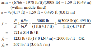
Check pressure on soil:
location of P and eccentricity, e:
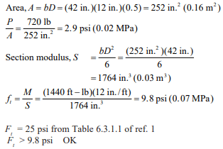
Check flexural stresses:
At 6 ft (1.8 m) depth:
P = ½ (6 ft)(40 pcf)(6 ft) = 720 lb (3203 N)
M = (720 lb)(⅓ x 6 ft) = 1440 ft-lb (1952 N-m)
Assume mortar bed is 50% of gross area:
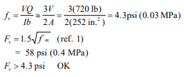
Check shear stresses:
REFERENCES
- Building Code Requirements for Masonry Structures, ACI 530-95/ASCE 5-95/TMS 402-95. Reported by the Masonry Standards Joint Committee, 1995.
- Standard Specification for Load-Bearing Concrete Masonry Units, ASTM C 90-94. American Society for Testing and Materials, 1994.
- Standard Specification for Mortar for Unit Masonry, ASTM C 270-92a. American Society for Testing and Materials, 1992.