Building Information Model (BIM) technology is becoming more and more common in the construction industry. This guide is intended to be used by designers to ensure that Segmental Retaining Walls (SRWs) are entered correctly and incorporated properly into models.
The guide provides step-by-step instructions using Revit to develop an SRW and all its components. The use of the Stacked Wall and Wall Sweep functions is explored in detail.
This guide was developed with the support of the NCMA Education and Research Foundation.
Segmental retaining walls are gravity retaining walls that rely primarily on their mass (weight) to resist the destabilizing force from retained soils (backfill) and surcharge loads. The system consists of manufactured concrete units that are placed without the use of mortar (dry stacked) and are usually connected through concrete shear keys or mechanical connectors. The units may also be used in combination with horizontal layers of soil reinforcement that extend into the backfill to increase the effective width and weight of the gravity mass.
This guide provides an overview for contractors and owners for the correct and successful installation of segmental retaining wall (SRW) systems, addressing the specific installation steps for engineered and non-engineered SRW systems.The information provided here covers the general installation guidelines for SRWs, site specific conditions should be appropriately evaluated by a qualified engineer. Users should reference the product-specific information provided by the block, geogrid and geotextile manufacturers for additional information unique to each system.
This TECH describes a method of analysis and design for conventional and geosynthetic-reinforced segmental retaining walls (SRWs) under seismic loading. The methodology extends the approach for structures under static loading to simple structures that may be required to resist additional dynamic loads due to earthquakes. The seismic design method described briefly in this Tech Note, and in detail in the CMHA Design Manual for Segmental Retaining Walls and SRWallv4 design software (refs. 1, 2), adopts a pseudo-static approach and uses the Mononobe-Okabe (M-O) method to calculate dynamic earth forces. The methodology adopts many of the recommendations contained in AASHTO/FHWA (refs. 3, 4) guidelines for the design and analysis of mechanically stabilized earth (MSE) structures subjected to earthquake loads. However, the CMHA Design Manual for Segmental Retaining Walls goes beyond the AASHTO/FHWA publications by addressing the unique stability requirements of SRWs that are constructed with a dry-stacked column of modular block units.
Properly designed reinforced SRWs subjected to seismic and/or dynamic loading will in general perform well due to their flexible nature and enhanced ductility. When an SRW requires seismic analysis, that evaluation should be performed in addition to the static analysis to satisfy all static and seismic safety factors, as outlined in the Design Manual for Segmental Retaining Walls. The project’s geotechnical engineer should select the ground acceleration design parameters considering the local experience, state of practice and site conditions. CMHA’s methodology uses a displacement approach that explicitly incorporates wall movement in the stability analysis, assuming small outward displacements are allowed, and reduces the Peak Ground Acceleration (PGA) following FHWA’s approach. It should be noted that outward displacements caused by “near” maximum probable magnitude earthquakes may bring SRWs outside of tolerable batter deviations, thereby requiring mitigation. As with any other structure, the intent of the seismic design is to prevent catastrophic failure (a failure leading to risk to life, limb, or property), and needs to be evaluated after a near design event.
For satisfactory performance in the field, the designer should specify the best construction and inspection practices, adequately addressing items such as materials, installation, compaction, and internal and external drainage (i.e., drain tiles, chimney drains, swales, etc.). For more details refer to SRW-TEC-005-09, Guide to Segmental Retaining Walls (ref. 5), SRW-TEC-008-12, Inspection Guide for Segmental Retaining Walls (ref. 6), and the CMHA Design Manual for Segmental Retaining Walls.
DESIGN ASSUMPTIONS
The CMHA seismic design and analysis methodology applies when the following conditions are met:
SRW structures are free-standing and able to displace horizontally at the base and yield laterally through the height of the wall. This assumption is based on installation recommendations of a system that is placed on soils and a flexible leveling pad of well-compacted gravel or unreinforced weak concrete that can crack if necessary.
Reinforced and retained soils are cohesionless, unsaturated, and homogeneous. Soil strength is described by the Mohr-Coulomb failure criterion. The apparent cohesive strength component reported under Mohr-Coulomb failure criterion is ignored for conservatism. Adequate drainage details should also accompany the design to ensure the soils remain unsaturated and that the assumed design conditions are reached and maintained.
Vertical ground acceleration is zero (kv = 0). Vertical ground acceleration is ignored based on the presumption that horizontal and vertical accelerations associated with a seismic event do not coincide.
Geometry is limited to infinite or broken-backslope, and constant horizontal foreslope angle.
Live surcharges are ignored at the top of the soil surface behind the facing column given their transient nature.
Retained and reinforced soils are placed to a depth corresponding to the full height of the SRW facing units (i.e. wall design height, H).
Cap units are ignored in the stability analysis and assumed to be securely attached such that they cannot be dislodged during ground shaking.
The stabilizing influence of the wall embedment is ignored with the exception of bearing capacity analyses.
No permanent surcharge or footing load exists within the active failure wedge.
Global stability involving failure of soil volumes beyond the base of the SRW unit column and/or geosynthetic reinforced fill zone is not considered.
SRW structures are built on competent foundations for which excessive settlement, squeezing or liquefaction are not potential sources of instability.
If there are more complex conditions, or for cases where M-O formulation leads to unrealistic results, it is recommended that numerical procedures using the same principles of M-O formulation be used. These include the well-known graphical Culmann method, Coulomb’s trial wedge method, or limit equilibrium slope stability programs that are outside of the scope of the CMHA Design Manual.
A limitation of the pseudo-static seismic design method presented here is that it can only provide an estimate of the margins of safety against SRW collapse or component failure, and does not provide any direct estimate of anticipated wall deformations. This is a limitation common to all limit-equilibrium design methods in geotechnical engineering.
GEOSYNTHETIC REINFORCED SEGMENTAL RETAINING WALLS— MODES OF FAILURE
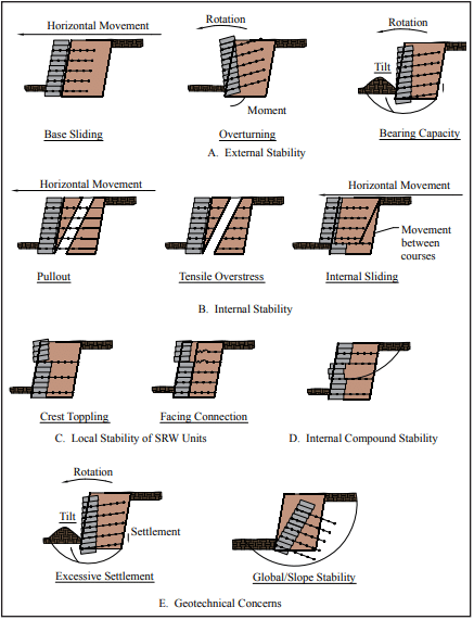
Stability analyses for geosynthetic reinforced SRW systems under static and seismic loading conditions involve separate calculations to establish factors of safety against external, internal, facing and internal compound modes of failure (Figure 1).
External stability calculations consider the reinforced soil zone and the facing column as a monolithic gravity structure. The evaluation of factors of safety against base sliding, overturning about the toe, and foundation bearing capacity is similar to that used for conventional reinforced concrete masonry gravity structures.
Internal stability analyses for geosynthetic reinforced soil walls are carried out to ensure that the structural integrity of the reinforced zone is preserved with respect to reinforcement over-stressing within the reinforced zone, pullout of geosynthetic reinforcement layers from the anchorage zone, and internal sliding along a reinforcement layer.
Facing stability analyses are carried out to ensure that the facing column is stable at all elevations and connections between the facing units and reinforcement layers are not over-stressed.
Internal compound stability analyzes the coherence of the block-geogrid system through potential compound slip circles that originate behind the soil-reinforced SRW and exit at the face of the wall.
Minimum recommended factors of safety (FS) of static and seismic design of geosynthetic reinforced SRW structures are given in Table 1. In general, FS for seismic design are taken as 75% of the values recommended for statically loaded structures following AASHTO/FHWA practice.
Potential concerns such as settlement of reinforced SRW structures due to compression, liquefaction, or squeezing of foundation soils is not considered here. Separate calculations for foundation-induced deformations may be required by the designer. In addition, slope instability involving volumes of soil beyond and below the base of the facing column is not considered. For global stability analysis, computer programs are available that consider the effects of both the stabilizing influence of reinforcement layers and destabilizing influence of seismic-induced ground acceleration (ref. 7).
Figure 1—SRW Failure Modes for Stability Analysis
Table 1—Recommended Minimum Factors of Safety and Design Criteria for Conventional/Reinforced SRWs
EXTERNAL STABILITY
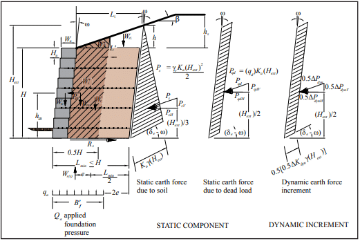
External stability calculations are similar to those for conventional static conditions, with the addition of the inertial force due to wall weight and the dynamic earth increment. Dynamic earth pressure, shown in Figure 2, is used to calculate the destabilizing forces in otherwise conventional expressions for the factor of safety against sliding along the foundation surface, overturning about the toe, and bearing capacity failure of the foundations soils. By convention, only half of the dynamic earth force increment is applied when calculating external seismic forces on conventional and reinforced SRWs. The simplified geometry and forces shown in Figure 2 are used in external stability calculations.
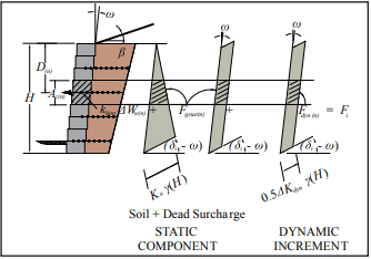
The contributory area approach (ref. 1, Sec. 7.5.2.2) used for the static stability analysis of SRWs is extended to the dynamic loading case (Figure 3). In this method, the reinforcement layers are modeled as tie-backs with the tensile force Fi in layer n equal to the earth pressure integrated over the contributory area Ac(n) at the back of the facing column plus the corresponding wall inertial force increment. Hence:
Fi(n) = khintΔWw(n) + Fgsta(n) + Fdyn(n)
where:
khintΔWw(n) = wall inertial force increment Fgsta(n) = static component of reinforcement load Fdyn(n) = dynamic component of reinforcement load.
Internal stability calculations are also similar to those carried out for conventional static conditions with the inclusion of dynamic earth pressure. For reinforced SRWs, full dynamic load is applied to internal stability with the exception of internal sliding that employs half ΔPdyn. Figure 3 shows the static and dynamic earth pressure distribution for internal stability calculations. The calculations for internal stability are presented in detail in Reference 1.
Figure 3—Geometry & Forces Used to Calculate Reinforcement Loads for Reinforced SRW Structures
FACING STABILITY
Facing stability calculations are similar to those used for the static analysis with the addition of the dynamic load. To evaluate the connection strength, the connection capacity at each reinforcement elevation is compared to the tensile force Fi already determined. The crest toppling is evaluated, determining the static, inertial and dynamic forces acting on the unreinforced top blocks. Only half of the dynamic load ΔPdyn is used to mirror the external overturning analysis.
INTERNAL COMPOUND STABILITY
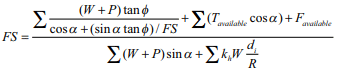
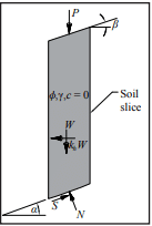
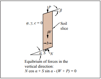
The consideration of seismic load for internal compound stability calculations is based on the addition of an inertial force (khW) associated with the mass of each soil slice (see Figure 4).
The incorporation of an additional dynamic load or inertial force is calculated as follows:
where:
di = vertical distance from the gravity center of the soil mass to the center of the slip surface R = radius of the slip surface Tavailable = available reinforcement force at the location of the intersection of the failure plane Favailable = available facing force at failure plane exit.
Figure 4—Soil Slice Showing Dynamic Load
FIELD PERFORMANCE
SRW performance during earthquakes is generally considered to be excellent (refs. 8, 9). Observations of SRWs within 31 miles (50 km) of the epicenter of both the Loma Prieta and Northridge earthquakes have shown that this type of retaining wall system can withstand considerable horizontal and vertical accelerations without experiencing unacceptable deformations. Similar to other structures subject to “near” maximum probable magnitude earthquakes, the designer should be aware that SRWs may need to be evaluated if damages are noticed, and repaired if necessary.
The design procedures presented in Design Manual for Segmental Retaining Walls, 3rd ed., provide a rational, detailed design methodology which, if followed, will allow designers to take advantage of SRW technology to build safe and economical retaining walls to withstand seismic forces.
Duncan, J.M., Low, B.K., and Shaeffer, V.R., STABGM: A Computer Program for Slope Stability Analysis of Reinforced Embankments, Virginia Polytechnic Institute,
Field Observations of Reinforced Soil Structures Under Seismic Loading, Collin, G., Chouery-Curtis, V.E., and Berg, R. R., Proceedings International Symposium on Earth Reinforcement Practice, Fukuoka, Japan, 1992.
Retaining Walls Stand Up to the Northridge Earthquake, Sandri, D., Geotechnical Fabrics Report 12 (4), 1994.
Segmental retaining walls (SRWs) function as gravity structures by relying on self-weight to resist the destabilizing forces due to retained soil (backfill) and surcharge loads. The self-weight of the SRW system is either the weight of the SRW units themselves including aggregate core fill if used (in the case of conventional SRWs) or the combined weight of the units, aggregate core fill if used and the reinforced soil mass (in the case of soil-reinforced SRWs).
Stability is provided by a coherent mass with sufficient width to prevent both sliding at the base and overturning about the toe of the structure under the action of lateral earth forces.
SRWs are durable and long lasting retaining wall systems. The typical size of SRW units, placed without mortar (dry- stacked), permits the construction of walls in locations with difficult access and allows the construction of tight curves or other complex architectural layouts. Segmental retaining walls are used in many applications, including landscaping walls, structural walls for changes in grade, bridge abutments, stream channelization, waterfront structures, tunnel access walls, wing walls and parking area support. This Tech Note provides a general overview of design considerations and the influences that height, soil, loads and geometry have on structural stability, based on Design Manual for Segmental Retaining Walls (ref. 1).
It is recommended that users of this Tech Note consult local building codes to determine additional SRW requirements and the engineering needs of their project. Where such specific requirements do not exist, CMHA recommends an engineered design performed by a registered professional on walls with a total (design) height, H, exceeding 4 ft (1.21 m) (for further detail, refer to SRW-TEC-008-12, Inspection Guide for Segmental Retaining Walls (ref. 3).
TYPES OF SEGMENTAL RETAINING WALLS
Conventional (Gravity) Segmental Retaining Walls
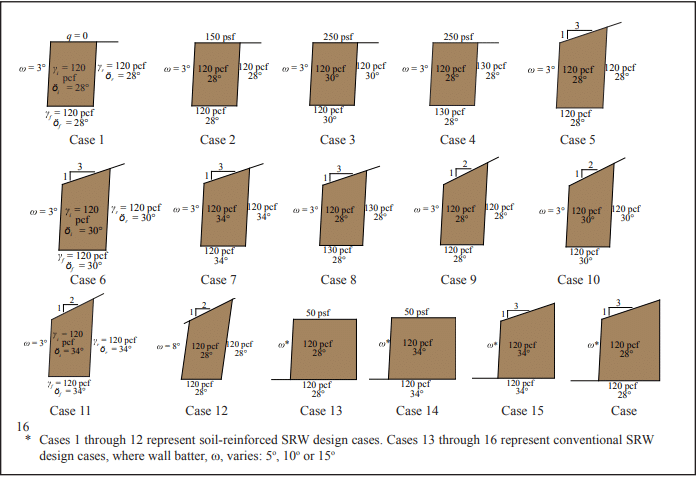
Conventional (gravity) SRWs retain soils solely through the self-weight of the SRW units. They can be constructed with either a single depth of unit or with multiple depths. The maximum wall height achievable using a conventional SRW is directly proportional to the unit’s weight, width, site geometry, surcharge load and retained soil type. Table 1 illustrates the effect of increasing the wall batter, unit width, unit’s in-place density (using either a solid unit or unit with aggregate core fill), and better quality backfill on the maximum height of a gravity wall.
Figure 1—Design Cases Corresponding to Table 1 and Figures 3 through 5
Soil-Reinforced Segmental Retaining Walls
Soil-reinforced SRWs are composite systems consisting of SRW units in combination with a mass of reinforced soil. The soil is stabilized by horizontal layers of reinforcement, typically a geosynthetic material. The reinforcement increases the effective width and weight of the gravity system.
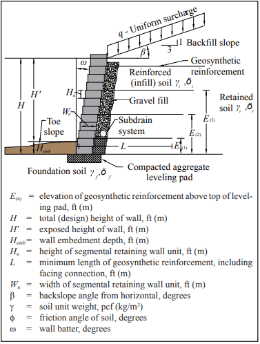
Geosynthetic reinforcement materials are high-tensile-strength polymeric materials. They may be geogrids or geotextiles, although current SRW construction typically uses geogrids. Figure 2 illustrates a typical soil-reinforced segmen- tal retaining wall and current design terminology.
The geosynthetic reinforcement is placed between the units and extended into the soil to create a composite gravity mass structure. This mechanically stabilized wall system, comprised of the SRW units and a reinforced soil mass, is designed to offer the required resistance to external forces associated with taller walls, surcharged structures, or more difficult soil conditions. Soil-reinforced SRWs may also be referred to as mechanically stabilized earth (MSE) walls, the generic term used to describe all forms of reinforced soil structures.
For soil-reinforced segmental retaining walls, geosynthetic reinforcement increases the mass of the composite SRW structure, and therefore increases its resistance to destabilizing forces. Geosynthetic length (L) is typically controlled by external stability or internal pullout capacity calculations. Increasing the length of the geosynthetic layers increases the SRW’s resistance to overturning, base sliding, bearing failure and geosynthetic pullout. In some cases, the length of the uppermost layer(s) is locally extended to provide adequate anchorage (pullout capacity) for the geosynthetic layers. The strength of the geosynthetic and the frictional interaction with the surrounding soil may also affect the geosynthetic length necessary to provide adequate pullout capacity. In addition, the required length to achieve minimum pullout capacity is affected by soil shear strength, backslope geometry and surcharge load (dead or live).
The minimum geosynthetic length required to satisfy external stability criteria is also a function of the soil shear strength and structure geometry (including wall batter, backslope, toe slope and surcharge). As the external driving force increases (as occurs with an increase in backslope angle, reduction in soil shear strength, or increase in external surcharge load (dead or live)), the length of the geosynthetic increases to satisfy minimum external stability requirements. Figures 3 through 5 illustrate the effect of backslope geometry, surcharge, soil unit weight and soil shear strength on the minimum required geosynthetic length to satisfy base sliding (FS = 1.5), overturning (FS = 1.5) and pullout (FS = 1.5). Regardless of the results of external stability analyses for sliding and overturning, the geogrid length (L) should not be less than 0.6H. The purpose of this empirical constraint is to prevent the construction of unusually narrow reinforced retaining walls. In addition, it is recommended that the absolute minimum value for L be 4 ft (1.2 m).
A sufficient number and strength of geosynthetic layers must be used to satisfy horizontal equilibrium with soil forces behind the wall and to maintain internal stability. In addition, the tension forces in the geosynthetic layers must be less than the design strength of the geosynthetic and within the allowable connection strength between the geosynthetic and the SRW unit. The optimum spacing of these layers is typically determined iteratively, usually with the aid of a computer program. Typically, the vertical spacing decreases with depth below the top of the wall because earth pressures increase linearly with depth.
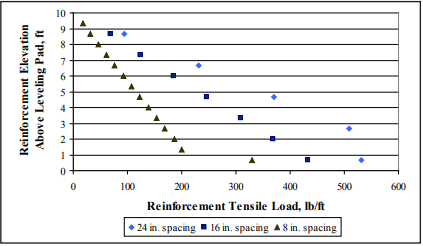
Vertical spacing between geosynthetic layers should be limited to prevent bulging of the wall face between geosynthetic connection points, to prevent exceeding the shear capacity between SRW units, to decrease the load in the soil reinforcement and at the geosynthetic-SRW unit connection interface. Figure 6 shows that smaller vertical reinforcement spacings reduce the geosynthetic reinforcement tensile load. Even when all internal and facial stability failure modes can be satisfied with larger spacings, however, a maximum vertical spacing between reinforcement layers of 24 in. (609 mm) is suggested to reduce construction stability issues. Note that some proprietary systems may be capable of supporting larger spacings: a 32 in. (813 mm) maximum spacing is suggested for these systems. This maximum spacing limits construction issues and also ensures that the reinforced soil mass behaves as a composite material, as intended by this design methodology. For SRW units less than or equal to 10 in. (254 mm) in depth, it is recommended that the maximum vertical spacing of the reinforcement layers be no more than twice the depth of the unit. For example, the maximum vertical spacing for a 9 in. (229 mm) deep modular block would be 18 in. (457 mm). Within these limits, the wall designer should choose an appropriate maximum reinforcement spacing for the proprietary system used.
Regardless of the reinforcement spacing, compaction of the reinforced fill zone is generally limited to 6 to 8 in. (152 to 203 mm) (compacted height) in order to achieve the necessary density and construction quality control. Compaction lift thickness in the retained zone is typically limited to the same height; however, thicker lifts can be accomplished if the specified density can be achieved throughout the entire lift thickness and it can be demonstrated that there are no adverse affects to the wall system performance or aesthetics. Regardless of the compaction method or equipment, the specified densities should be met and any variation from the approved specifications must be authorized by the SRW design engineer of the project.
Figure 3—Flat Slope Cases, Varying f, g and q—Cases 1, 2, 3 and 4
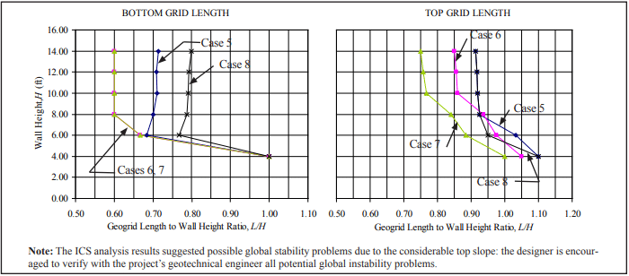
Figure 4—3:1 Top Slope Cases
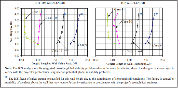
Figure 5—2:1 Top Slope Cases
Figure 6—Influence of Reinforcement Vertical Spacing on Calculated Reinforcement Tensile Load
Gravel Fill and Drainage Materials
Whenever possible, water should be directed away from SRWs. However, when water does reach an SRW, proper drainage components should be provided to avoid erosion, migration of fines, and hydrostatic pressure on the wall. Drainage features of the SRW will depend on site-specific groundwater conditions. The wall designer should provide adequate drainage features to collect and evacuate water that may potentially seep at the wall. The civil site engineer is typically responsible for the design of surface drainage structures above, below and behind the wall and the geotechnical engineer is typically responsible for foundation preparation and subsurface drainage beneath a wall. Reference 1 addresses in detail the drainage features and materials required for various ground water conditions on SRWs.
The gravel fill (formerly known as the drainage aggregate) and drain pipe shown on Figure 2 should only be relied on to remove incidental water—they are not meant to be the primary drainage path of the system. The gravel fill acts mainly as a compaction aid to reduce horizontal compaction stresses on the back of the SRW units during construction. It also prevents retained soils from washing through the face of the wall when designed as a soil filter, and facilitates drainage of incidental water, thereby relieving hydrostatic pressure or seepage forces.
The drain pipe collects and evacuates any water in the system through weep holes (maximum 50 ft (15.2 m) o.c. spacing) or directly to a drainage collection system. The elevation and diameter of the drain pipe should be determined by the wall designer depending on the specific site conditions.
The gravel fill should consist of at least 12 in. (305 mm) of a free-draining aggregate installed behind of the SRW units, and the drain pipe have a minimum diameter of 3 in. (75 mm).
Wall Batter
Segmental retaining walls are generally installed with a small horizontal setback between units, creating a wall batter into the retained soil (ω in Figure 2). The wall batter compensates for any slight lateral movement of the SRW face due to earth pressure and complements the aesthetic attributes of the SRW system. For conventional (gravity) SRWs, increasing the wall batter increases the wall system stability.
Unit Size and Shear Capacity
All SRW units provide a means of transferring lateral forces from one course to the next. Shear capacity provides lateral stability for the mortarless SRW system. SRW units can develop shear capacity by shear keys, leading lips, trailing lips, clips, pins or compacted columns of aggregate in open cores. In conventional (gravity) SRWs, the stability of the system depends primarily on the mass and shear capacity of the SRW units: increasing the SRW unit width or weight provides greater stability, larger frictional resistance, and larger resisting moments. In soil-reinforced SRWs, heavier and wider units may permit a greater vertical spacing between layers of geosynthetic, minimize the potential for bulging of the wall face. For design purposes, the unit weight of the SRW units includes the gravel fill in the cores if it is used.
Wall Embedment
Wall embedment is the depth of the wall face below grade (Hemb in Figure 2). The primary benefit of wall embedment is to ensure the SRW is not undermined by soil erosion in front of the wall. Increasing the depth of embedment also provides greater stability when site conditions include weak bearing capacity of underlying soils, steep slopes near the toe of the wall, potential scour at the toe (particularly in waterfront or submerged applications), seasonal soil volume changes or seismic loads.
The embedment depth is determined based on the wall height and toe slope conditions (see Table 2), although the absolute minimum suggested Hemb is 6 in. (152 mm).
Table 2—Minimum Wall Embedment Depth
Surcharge Loadings
Often, vertical surcharge loadings (q in Figure 2) are imposed behind the top of the wall in addition to load due to the retained earth. These surcharges add to the lateral pressure on the SRW structure and are classified as dead or live load surcharges.
Live load surcharges are considered to be transient loadings that may change in magnitude and may not be continuously present over the service life of the structure. In this design methodology, live load surcharges are considered to contribute to destabilizing forces only, with no contribution to stabilizing the structure against external or internal failure modes. Examples of live load surcharges are vehicular traffic and bulk material storage facilities.
Dead load surcharges, on the other hand, are considered to contribute to both destabilizing and stabilizing forces since they are usually of constant magnitude and are present for the life of the structure. The weight of a building or another retaining wall (above and set back from the top of the wall) are examples of dead load surcharges.
DESIGN RELATIONSHIPS
Table 1 summarizes the influence of increasing the wall batter, increasing the unit width, increasing the unit’s in-place density, and using better quality backfill on the maximum constructible height of a gravity SRW to satisfy sliding and overturning.
Figures 3 through 5 summarize the influences wall geometry, backslope and soil shear strength have on the minimum required reinforcement length to satisfy base sliding, overturning and pullout for a reinforced SRW.
These design relationships were generated using conservative, generic properties of SRW units. They are not a substitute for project-specific design, since differences between properties assumed in the tables and project-specific parameters can result in large differences in final design dimensions or factors of safety. Although wall heights up to 8 ft (2.44 m) for conventional (gravity) walls and 14 ft (4.28 m) for soil-reinforced walls are presented, properly engineered walls can exceed these heights.
For a detailed discussion of design and analysis parameters, the Design Manual for Segmental Retaining Walls (ref. 1) should be consulted. Design cases 1 through 16 are illustrated in Figure 1. All results shown were calculated using the software SRWall 4.0 (ref. 2) providing the appropriate geosynthetic lengths to satisfy sliding, overturning, and pullout (reinforced walls only) safety factors; or the maximum gravity wall height to satisfy sliding, overturning and internal shear. The final number, distribution and strength of the geogrids can only be determined by a designer for each specific SRW unit-geogrid combination to guarantee the appropriate safety factors for internal, facial stability and Internal Compound Stability (ICS) are met (for more detailed information, see Reference 1). The ICS can be met by reducing the geogrid spacing or increasing the grid length or strength: the examples presented here were calculated by reducing the geogrid spacing and maintaining the maximum and minimum geogrid lengths for convenience. See SRW-TEC-003-10, Segmental Retaining Wall Global Stability, (ref. 4) for more detailed information.
Large or commercial SRWs might also require foundation soil competency, settlement, and global stability analyses for a final design in coordination with other professionals in the project that are not addressed here (for more details on roles and responsibilities see SRW-TEC-002-10, Roles and Responsibilities on Segmental Retaining Wall Projects (ref. 5)). If the foundation and global analyses ultimately require a modification to the wall design, this must be done in coordination with the SRW designer.
EXAMPLE
A reinforced SRW is specified for a project that has the following characteristics:
H= 10 ft (3.0 m) Backslope 3:1 Live surcharge= 0 psf All soils Φ= 28° and γ = 120 pcf (1,922 kg/m³)
Determine the approximate geogrid lengths (L) at the bottom and top of the retaining wall.
Solution
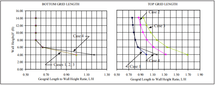
Determine the case that applies to this problem using Figure 1: Case 5 for this example. Using Figure 4 (3:1 backslope), find L/H for the given soil conditions and for the design height of 10 ft (3.0 m).
Bottom geogrid: L/H= 0.71; Lbottom = 0.71 x 10 ft = 7.1 ft (2.2 m) Top geogrid: L/H= 0.92; Ltop = 0.92 x 10 ft = 9.2 ft (2.8 m)
For estimating purposes, the volume of excavation and reinforced fill could be determined from the obtained data. The number, strength and distribution of the geogrids can only be determined by a designer for the specific SRW unit-geogrid combination to comply with the appropriate safety factors for internal, facial stability and ICS. The ICS is dependent on the spacing, length and strength of the geogrids: the designer is encouraged to perform the appropriate calculations to verify the distribution of the geosynthetics.
The general mass movement of a segmental retaining wall (SRW) structure and the adjacent soil is called global stability failure. Global stability analysis is an important component of SRW design, particularly under the following conditions:
groundwater table is above or within the wall height of the SRW,
a 3H:1V or steeper slope at the toe or top of the SRW,
for tiered SRWs,
for excessive surcharges above the wall top,
for seismic design, and
when the geotechnical subsurface exploration finds soft soils, organic soils, peat, high plasticity clay, swelling or shrinking soils or fill soil.
The designer should also review local code requirements applicable to designing soil retention structures.
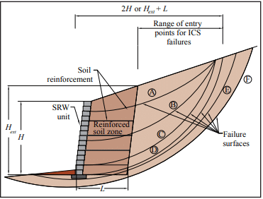
There are two primary modes of global stability failure: deep-seated and compound. A deep-seated failure is characterized by a failure surface that starts in front of an SRW, passes below the base of the wall and extends beyond the tail of the geosynthetic reinforcement (see Figure 1, surface F).
Compound failures are typically described by a failure surface that passes either through the SRW face or in front of the wall, through the reinforced soil zone and continues into the unreinforced/retained soil (Fig. 1, surfaces A through E). A special case of the compound failure is the Internal Compound Stability (ICS) failure surface that exits at the SRW face above the foundation soil (Fig. 1, surfaces A through D).
Figure 1—Global Stability Failures
GLOBAL STABILITY ANALYSIS
Several methods of analysis (such as Janbu, Spencer and Bishop) have been developed to analyze the global stability in a soil mass. The Bishop’s method is the most commonly used. It models a group of slices and the forces acting on each slice as shown in Figure 2. Limit equilibrium requirements are applied to the slices comprising the soil structure. The factor of safety against sliding is defined as the ratio of the maximum shear possessed by the soil on the trial failure surface plus contributions from the soil reinforcement (τavailable) to the shear resistance developed along the potential failure surface (τmobilized), i.e.:
FS= τavailable/τmobilized or resistance/driving.
Limit equilibrium methods of analysis are typically used to determine the global stability of the SRW. These methods assume that the SRW, the retained soil, and the foundation soil will fail along a critical slip (failure) surface generated by the force of gravity. The critical slip surface is commonly assumed as a circular arc, logarithmic spiral arc, curve, single plane or multiple planes to simulate the possible sliding movement.
In most limit equilibrium analyses, the minimum shear strength required along a potential failure surface to maintain stability is calculated and then compared to the available shear strength of the soil. The factor of safety is assumed to be constant along the entire failure surface. The design factor of safety for global stability is typically between 1.3 and 1.5, and depends on the criticality of the structure and how well the site conditions are defined.
The global stability analysis is an iterative process where as many as 250 trial failure surfaces are assumed and analyzed to determine the critical failure surface (i.e. minimum factor of safety). For this reason, the slope stability analyses are usually performed using computer programs that implement one or more methods. Many software programs have been developed to analyze the global stability of unreinforced soil structures. There are, however, only a limited number of programs that include the stabilizing effects of the geosynthetic reinforcement used to construct a soil-reinforced SRW. ReSSA (ref. 1) is one of the specialized programs developed for the Federal Highway Administration.
Figure 2—Representative Slope Slice for Bishop’s Method of Analysis (ref. 3)
Internal Compound Stability
Internal Compound Stability (ICS) affects the internal components of the retaining wall system, including the facing elements and reinforced zone. Because ICS is influenced by loading conditions outside the reinforced fill area, it is a special case of a larger compound analysis.
The CMHA Design Manual for Segmental Retaining Walls (ref. 3) provides specific guidelines for ICS analysis. The failure surfaces are evaluated by defining a range of possible entry points located behind the soil-reinforced SRW and exit points at the face of the wall. The entry points are located at a distance that is the larger of twice the wall height (2H) and the height of the projection from the tail of the reinforcement layers to the surface plus a distance equal to the length of the reinforcement (Hext + L) (see Figure 1).
To analyze the ICS failure on soil-reinforced SRWs, the components of the SRW (soil reinforcement and facing) are considered to help resist the unbalanced forces of the system:
To simplify the ICS analysis, CMHA has developed SRWall 4.0 Software (ref. 2).
Factors Affecting the Global Stability and Internal Compound Stability (ICS) of SRWs
The global factor of safety of an SRW is a function of: the soil characteristics, groundwater table location, site geometry (i.e., sloping toe or crest, tiered walls), and the length, strength and vertical location of soil reinforcement (geosynthetic). The effects of each of these are briefly discussed below.
Soil Characteristics—Weak foundation soils increase the potential for deep-seated stability problems. Low strength reinforced soil will contribute to compound stability problems and low strength retained soils may contribute to either deep-seated or compound failure modes.
Groundwater Table—If the groundwater table is shallow (i.e., close to the toe of the wall) the long-term shear strength (i.e., effective shear strength) of the foundation soil will be reduced. This reduction in strength is directly related to the buoyant effect of the groundwater. The effective weight of the soil is reduced by approximately 50%, which reduces the shear strength along the failure surface.
Geometry—A sloping toe at the bottom of an SRW reduces the resisting forces when analyzing failure surfaces exiting in front of the SRW (deep-seated or compound). As the resisting force decreases, the global factor of safety also decreases. The ICS does not evaluate the influence of front slopes on the stability of SRWs.
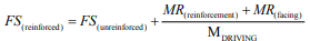
Figure 3 illustrates the design case for a parametric analysis with top and toe slopes condition for a 10-ft (3.05-m) high wall with a horizontal crest slope founded on a foundation soil with a friction angle of 30°.
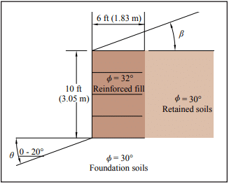
Figure 4 shows the change in factor of safety for deep-seated failure as a function of the toe slope angle. However, ICS analysis is not influenced by these changes and remains constant for the different toe variations.
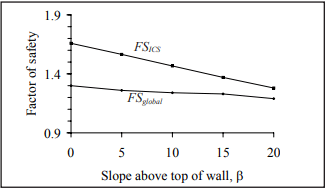
An increase of the slope above the wall decreases the SRW global stability factor of safety. Figure 5 shows the change in factor of safety for the design case used earlier (with the exception that the toe is level and the crest slope varies). In this case, evaluation of the wall with this geometry shows a larger reduction in safety factor for ICS than for global stability.
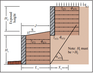
Tiered Walls—The CMHA Design Manual for Segmental Retaining Walls (ref. 3) provides specific guidelines for tiered SRWs with respect to the spacing between tiers and the effect of the upper wall on the internal and external stability of the lower wall (see Figure 6). When the setback of the upper wall, J, is greater than the height of the lower wall, H1, the internal design of the lower wall is not affected by the upper wall. However, this is not true for global stability. Global stability must be checked for all tiered walls.
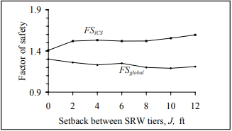
Figure 7 shows the variation in the global factor of safety for two 10-ft (3.05-m) high tiered walls with horizontal crest slopes as a function of the setback J. In this example, the reinforcement length for both walls is 12 ft (3.66 m), which is 0.6 times the combined height of both walls. For this particular example, constructing a tiered wall versus a single wall 20 ft (6.10 m) high (i.e., J = 0) reduces the global factor of safety from 1.3 to 1.2. From the ICS analysis, a tiered wall has better safety factors and the stability is increased when the distance between tiers is increased.
Soil Reinforcement—Generally speaking, increasing the spacing between reinforcement layers increases the potential for compound failures. Shortening the length of the reinforcement will also increase the potential for both compound and deep-seated failure. Changes in the design strength of the reinforcement often have the smallest impact on the global stability.
Figure 3—Typical Section for Figures 4 and 5
Figure 4—Effect of Sloping Toe Angle
Figure 5—Effect of Slope Above Top of Wall
Figure 6—Tiered SRW
Figure 7—Effect of Tiered SRW Setback
CONCLUSIONS
The global stability analysis (deep-seated and compound) of an SRW is an important consideration during the SRW design stage in order to assess the overall wall performance and the coherence of the system. Whenever the structure is influenced by weak soils, ground water tables, slopes at the top or toe of the structure or seismic conditions, an experienced professional should verify that all possible failure conditions have been evaluated.
When the global factor of safety of an SRW is below the design requirement, stability may be increased by increasing the reinforcement length or strength, or by decreasing the space between reinforcement layers. If the changes on the internal structure of the SRW do not improve the factors of safety, soil characteristics can be improved, water can be addressed with appropriate management and geometry can be modified.
When designing SRWs with these conditions, it is important to maintain the coordination among the appropriate professionals to help ensure the success of the job. Consideration must also be given to the impact that each variable has on the SRW stability:
Increasing the foundation, reinforced and/or retained soil shear strength (using ground improvement techniques or changing soil type).
Adding external and internal drainage features reduces surcharges and improves soil properties.
When a slope occurs at the toe of a wall, changing the geometry of the wall slope may also increase stability. For example, placing the SRW at the bottom of the slope and having a slope above the wall instead may increase the stability to an acceptable level.
A change in the toe slope has a more drastic effect on FSglobal than does a change in the slope above the wall.
An increase in the slope above the wall reduces the ICS safety factor more than the global stability safety factor.
Global stability analysis is a complex analytical procedure. However, computer software is available which greatly reduces the time required for the analysis.
NOTATIONS:
b = width of slice, ft (m) c = cohesion of soil, psf (MPa) FS = factor of safety FSglobal = global factor of safety FSICS = ICS factor of safety FS(reinforced) = the reinforced factor of safety of the soil FS(unreinforced) = unreinforced factor of safety of the soil H = total height of wall, ft (m) Hext = height of back of reinforced wall over which the active earth pressure for external stability is calculated, ft (m) H1 = height of lower wall for tiered SRWs, ft (m) H2 = exposed height of upper wall for tiered SRW, ft (m) J = setback between SRW tiers, ft (m) L = length of geosynthetic soil reinforcement, ft (m) MR(reinforcement) = the resisting moment generated by the reinforcement layers that intercept the slip surface MR(facing) = the resisting contribution of the facing at the exit of the potential slip circle. MDRIVING = the driving force generated by the weight and surcharges present on the potential slip circle. N = total normal force, N = N’ + ul, lb/ft (N/m) N’ = effective normal force, lb/ft (N/m) P = external load, lb/ft (kN/m) ql = soil surcharge, lb/ft² (N/m²) R = radius of the circular slip failure, ft (m) S = ratio of horizontal offset to vertical rise between tiers of slope W = total weight of soil in slice plus surcharge if present, lb/ ft (N/m) X1 = length of influence zone for upper tier, ft (m) αe = orientation of the critical Coulomb failure surface β = soil slope above top of wall, degrees γ = soil unit weight, pcf (kN/m³) θ = toe angle, degrees Φ = friction angle of soil, degrees τavailable = maximum shear strength possessed by the soil on the trial failure surface plus contributions from soil reinforcement, lb/ft (N/m) τmobilized = shear resistance necessary for equilibrium, lb/ft (N/m)
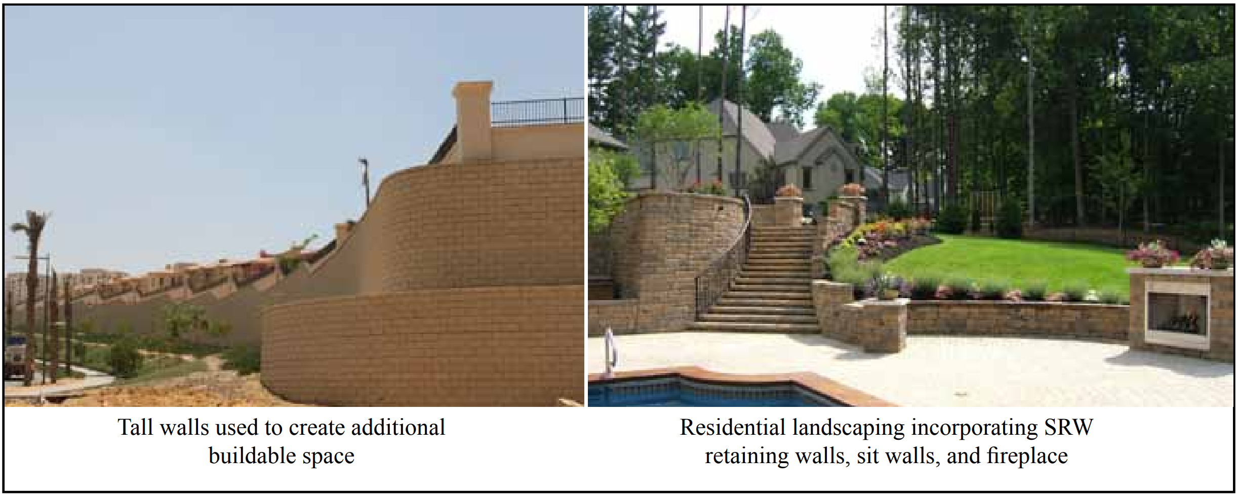
Mortarless segmental retaining walls are a natural enhancement to a variety of landscape projects. Applications range from 8 in. (204 mm) high terraces for erosion control to retaining walls 20 ft (6.1 m) or more in height. The individual concrete units can be installed to virtually any straight or curved plan imaginable.
Segmental retaining walls are used to stabilize cuts and fills adjacent to highways, driveways, buildings, patios and parking lots, and numerous other applications. Segmental retaining walls replace treated wood, cast-in-place concrete, steel, and other retaining wall systems because they are durable, easier and quicker to install, and blend naturally with the surrounding environment. Concrete units resist deterioration when exposed to the elements without the addition of toxic additives which can threaten the environment.
A variety of surface textures and features are available, including split faced, stone faced, and molded face units, any one of which may be scored, ribbed, or colored to fit any project application. Construction of segmental retaining walls does not require heavy equipment access, nor does the system require special construction skills to erect. Manufactured concrete retaining wall units generally weigh 30 to 100 lb (14 to 45 kg) each and are placed by hand on a level or sloped gravel bed.
Successive courses are stacked dry on the course below in the architectural pattern desired. Mechanical interlocking and/or frictional shear strength between courses resists lateral soil pressure. In low-height walls, overturning forces due to soil pressure are resisted by the weight of the units, sometimes aided by an incline toward the retained soil. Higher walls resist lateral soil pressures by inclining the wall toward the retained earth, or by other methods such as anchoring to geosynthetic reinforcement embedded in the soil. Further information on the design of segmental retaining walls can be found in Design Manual for Segmental Retaining Walls (ref. 1).
Segmental retaining wall units are factory-manufactured to quality standards in accordance with ASTM C1372, Standard Specification for Segmental Retaining Wall Units (ref. 2). These requirements are intended to assure lasting performance, little or no maintenance, structural integrity, and continued aesthetic value.
Segmental retaining wall units complying with the requirements of ASTM C1372 have been successfully used and have demonstrated good field performance. Segmental retaining wall units currently being supplied to the market should be produced in accordance with this standard so that both the purchaser and the supplier have the assurance and understanding of the expected level of performance of the product.
ASTM C1372 covers both solid and hollow units which are to be installed without mortar (dry-stacked). Units are designed to interlock between courses or to use mechanical devices to resist sliding due to lateral soil pressure. If particular features are desired, such as a specific weight classification, higher compressive strength, surface texture, finish, color, or other special features, they should be specified separately by the purchaser. However, local suppliers should be consulted as to the availability of units with such features before specifying them.
Figure 1—Examples of Segmental Retaining Wall Installations
Materials
ASTM C1372 includes requirements that define acceptable cementitious materials, aggregates, and other constituents used in the manufacture of concrete segmental retaining wall units. These requirements are similar to those included in ASTM C90, Standard Specification for Loadbearing Concrete Masonry Units (ref. 3).
Compressive Strength
Minimum compressive strength requirements for segmental retaining wall units are included in Table 1. Units meeting or exceeding these strengths have demonstrated the integrity needed to resist the structural demands placed on them in normal usage. These demands include impact and vibration during transportation, the weight of the units above them in the wall, nonuniform distribution of loads between units, and the tensile stresses imposed as a result of typical wall settlement.
Segmental retaining wall units will not fail in service due to compressive forces since axial loads are only a result of self-weight. Due to the direct relationship between compressive strength and tensile strength, this minimum requirement is used to ensure overall performance.
Compressive strength testing of full size units is impractical due to the large size and/or unusual shape of some segmental retaining wall units. Therefore, compressive strength of these units is determined from testing coupons cut from the units. The results of tests on these smaller coupons will typically yield lower strengths than if the larger, full-size specimen were tested. The reason for the difference is size and aspect ratio. However, it is important to keep in mind that the compression test is not intended to determine the load-carrying capacity of the unit, since segmental retaining walls are not designed to carry vertical structural loads. Compressive strength is used solely to assess the quality of the concrete.
Because tested strengths are affected by size and shape of the specimen tested, it is important that all retaining wall units be tested using a similar size and shape. ASTM C140/ C140M, Standard Method for Sampling and Testing Concrete Masonry Units and Related Units (ref. 4) requires that specimens cut from full-size units for compression testing must be a coupon with a height to thickness ratio of 2 to 1 before capping and a length to thickness ratio of 4 to 1. The coupon width is to be as close to 2 in. (51 mm) as possible based on the configuration of the unit and the capacity of the testing machine, but not less than 1.5 in. (38 mm). The preferred size is 2 x 4 x 8 in. (51 x 102 x 203 mm) (width x height x length). The coupon height is to be in the same direction as the unit height dimension. If these procedures are followed, the compressive strength of the coupon is considered the strength of the whole unit.
Alignment of the specimen in the compression machine is critical. Care should be taken in capping the test specimen to assure that capping surfaces are perpendicular to the vertical axis of the specimen. Capping needs to be performed in accordance with ASTM C1552, Standard Practice for Capping Concrete Masonry Units, Related Units and Masonry Prisms for Compression Testing (ref. 5).
Saw-cutting is the required method of extracting a test specimen from a full-size unit. Proper equipment and procedures are essential to prevent damaging the test specimen as a result of saw-cutting. Water-cooled, diamond-tipped blades on a masonry table saw are recommended. The blade should ideally have a diameter sufficient enough to make all cuts in a single pass. Manufacturers of the unit (or licensors of proprietary shapes) should be consulted about recommended locations for obtaining the compression specimen.
a Based on oven-dry density of concrete.
Weight Classification
Weight classifications for segmental retaining wall units are defined in Table 1. The three classifications, lightweight, medium weight, and normal weight, are a function of the oven dry density of the concrete. Most segmental retaining wall units fall into the normal weight category.
Absorption
Absorption requirements are also included in Table 1. This value is used to represent the volume of voids in a concrete masonry unit, including voids inside the aggregate itself. The void space is measured by determining the volume of water that can be forced into the unit under the nominal head pressure that results from immersion in a tank of water.
Lightweight aggregates used in the production of lightweight and medium weight units contain voids within the aggregate itself that also fill with water during the immersion test. While reduced voids indicate a desired tightly compacted unit, tightly compacted lightweight and medium weight units will still have higher absorption due to the voids in the aggregates. For this reason the maximum allowable absorption requirements vary according to weight classification.
Similar to compression testing, it generally is not practical to test full-size retaining wall units in absorption tests due to their size and weight. Therefore, ASTM C140/C140M permits the testing of segments saw-cut from full-size units to determine absorption and density. When reduced-size units are used for absorption testing, the reduced-size specimen must have an initial weight of at least 20% of the full-size unit weight. This is intended to ensure that a sufficiently sized specimen is tested in order for the results to be representative of the entire unit.
Absorption limits are typically expressed as mass (weight) of water absorbed per concrete unit volume. This is preferred to expressing by percentage which permits a denser unit to absorb more water than a lighter weight unit.
Testing larger specimens requires particular attention to drying times, because it takes a greater length of time to remove all moisture from larger masses. ASTM C140/C140M requires that specimens be dried for a period of not less than 24 hours at a temperature of at least 221°F (105°C). The 24-hour time period does not start until the oven reaches the specified temperature. When placing larger specimens in an oven, it may take several hours for the oven to reach the prescribed temperature. ASTM C140/C140M then requires that specimen weights be determined every two hours to make sure that the unit is not still losing water weight (maximum weight loss in two hours must be less than 0.2% of the previous specimen weight). This will require 48 hours or more for some specimens. If not adequately dried, reported absorptions will be lower than the actual value.
Permissible Variations in Dimensions
Mortarless systems require consistent unit heights to maintain vertical alignment and level of the wall. For this reason, permissible variation in dimensions is limited to ±⅛ in. (3.2 mm) from the specified standard dimensions. Regarding dimensions, “width” refers to the horizontal dimension of the unit measured perpendicular to the face of the wall. “Height” refers to the vertical dimension of the unit as placed in the wall. “Length” refers to the horizontal dimension of the unit measured parallel to the running length of the wall.
Dimensional tolerance requirements for width are waived for split faced and other architectural surfaces. The surface is intended to be rough to satisfy the architectural features desired and cannot be held to a specific tolerance.
Finish and Appearance
Minor cracks incidental to the usual method of manufacture or minor chipping resulting from customary methods of handling in shipment and delivery are not grounds for rejection. Units used in exposed wall construction are not to show chips or cracks or other imperfections in the exposed face when viewed from a distance of not less that 20 ft (6.1 m) under diffused lighting. In addition, up to five percent of a shipment are permitted to: contain chips on the finished face not larger than 1 in. (25.4 mm) in any dimension; contain cracks on the finished face wider than 0.02 in. (0.5 mm) and longer than 25% of the nominal height of the unit; have dimensions outside the permissible dimensional variations; or be broken.
Freeze-Thaw Durability
Segmental retaining wall units may be used in aggressive freezing and thawing environments. Freeze-thaw damage can occur when units are saturated with water and then undergo temperature cycles that range from above to below the freezing point of water. Freezing and thawing cycles and a constant source of moisture must both be present for potential damage to occur.
Many variations can exist in exposure conditions, any of which may affect the freeze-thaw durability performance of the units. Such variations include: maximum and minimum temperatures, rate of temperature change, duration of temperatures, sunlight exposure, directional facing, source and amount of moisture, chemical exposure, deicing material exposure, and others.
When units are used in applications where freezing and thawing under saturated conditions can occur, ASTM C1372 includes three different methods of satisfying freeze-thaw durability requirements:
Proven field performance,
Five specimens shall have less than 1% weight loss after 100 cycles in water using ASTM C1262 (ref. 6), or
Four of five specimens shall have less than 1.5% weight loss after 150 cycles in water using ASTM C1262.
Segmental retaining wall units in many areas of the country are not exposed to severe exposures. Therefore, the requirements above apply only to “areas where repeated freezing and thawing under saturated conditions occur.”
Freeze-thaw durability tests are conducted in accordance with ASTM C1262, Standard Test Method for Evaluating the Freeze-Thaw Durability of Dry-Cast Segmental Retaining Wall Units and Related Concrete Units, (ref. 6) using water or saline as the test solution. For most applications, tests in water are considered sufficient. If the units will be exposed to deicing salts on a regular basis, consideration should be given to performing the tests in saline. However, no pass/fail criteria has been adopted by ASTM for saline testing.
Compliance
ASTM C1372 also provides guidance regarding compliance. If a sample fails, the manufacturer can remove or cull units from the shipment. Then a new sample is selected by the purchaser from the remaining units of the shipment and tested, which is typically paid for by the manufacturer. If the second sample passes, then the remaining units of the lot being sampled are accepted for use in the project. If the second sample fails; however, the entire lot represented by the sample is rejected.
The specification also provides guidance on responsibility for paying for the tests. Unless otherwise provided for in the contract, the purchaser typically pays for the testing if the units pass the test. However, if the units fail the test, the seller bears the cost of the testing. See SRW-TEC-007-15Sampling and Testing Segmental Retaining Wall Units (ref. 7) for more detailed information on SRW unit sampling, testing, and acceptance.
Standard Specification for Dry Cast Segmental Retaining Wall Units, ASTM C1372-14. ASTM International, 2014.
Standard Specification for Loadbearing Concrete Masonry Units, ASTM C90-14. ASTM International, 2014.
Standard Methods for Sampling and Testing Concrete Masonry Units and Related Units, ASTM C140/C140M-14a. ASTM International, 2014.
Standard Practice for Capping Concrete Masonry Units, Related Units and Masonry Prisms for Compression Testing, ASTM C1552-14. ASTM International, 2014.
Standard Test Method for Evaluating the Freeze-Thaw Durability of Dry-Cast Segmental Retaining Wall Units and Related Concrete Units, ASTM C1262-10. ASTM International, 2010.