Resources

Seismic Design of Segmental Retaining Walls

INTRODUCTION

This TECH describes a method of analysis and design for conventional and geosynthetic-reinforced segmental retaining walls (SRWs) under seismic loading. The methodology extends the approach for structures under static loading to simple structures that may be required to resist additional dynamic loads due to earthquakes. The seismic design method described briefly in this Tech Note, and in detail in the CMHA Design Manual for Segmental Retaining Walls and SRWallv4 design software (refs. 1, 2), adopts a pseudo-static approach and uses the Mononobe-Okabe (M-O) method to calculate dynamic earth forces. The methodology adopts many of the recommendations contained in AASHTO/FHWA (refs. 3, 4) guidelines for the design and analysis of mechanically stabilized earth (MSE) structures subjected to earthquake loads. However, the CMHA Design Manual for Segmental Retaining Walls goes beyond the AASHTO/FHWA publications by addressing the unique stability requirements of SRWs that are constructed with a dry-stacked column of modular block units.

Properly designed reinforced SRWs subjected to seismic and/or dynamic loading will in general perform well due to their flexible nature and enhanced ductility. When an SRW requires seismic analysis, that evaluation should be performed in addition to the static analysis to satisfy all static and seismic safety factors, as outlined in the Design Manual for Segmental Retaining Walls. The project’s geotechnical engineer should select the ground acceleration design parameters considering the local experience, state of practice and site conditions. CMHA’s methodology uses a displacement approach that explicitly incorporates wall movement in the stability analysis, assuming small outward displacements are allowed, and reduces the Peak Ground Acceleration (PGA) following FHWA’s approach. It should be noted that outward displacements caused by “near” maximum probable magnitude earthquakes may bring SRWs outside of tolerable batter deviations, thereby requiring mitigation. As with any other structure, the intent of the seismic design is to prevent catastrophic failure (a failure leading to risk to life, limb, or property), and needs to be evaluated after a near design event.

For satisfactory performance in the field, the designer should specify the best construction and inspection practices, adequately addressing items such as materials, installation, compaction, and internal and external drainage (i.e., drain tiles, chimney drains, swales, etc.). For more details refer to SRW-TEC-005-09, Guide to Segmental Retaining Walls (ref. 5), SRW-TEC-008-12, Inspection Guide for Segmental Retaining Walls (ref. 6), and the CMHA Design Manual for Segmental Retaining Walls.

DESIGN ASSUMPTIONS

The CMHA seismic design and analysis methodology applies when the following conditions are met:

  • SRW structures are free-standing and able to displace horizontally at the base and yield laterally through the height of the wall. This assumption is based on installation recommendations of a system that is placed on soils and a flexible leveling pad of well-compacted gravel or unreinforced weak concrete that can crack if necessary.
  • Reinforced and retained soils are cohesionless, unsaturated, and homogeneous. Soil strength is described by the Mohr-Coulomb failure criterion. The apparent cohesive strength component reported under Mohr-Coulomb failure criterion is ignored for conservatism. Adequate drainage details should also accompany the design to ensure the soils remain unsaturated and that the assumed design conditions are reached and maintained.
  • Vertical ground acceleration is zero (kv = 0). Vertical ground acceleration is ignored based on the presumption that horizontal and vertical accelerations associated with a seismic event do not coincide.
  • Geometry is limited to infinite or broken-backslope, and constant horizontal foreslope angle.
  • Live surcharges are ignored at the top of the soil surface behind the facing column given their transient nature.
  • Retained and reinforced soils are placed to a depth corresponding to the full height of the SRW facing units (i.e. wall design height, H).
  • Cap units are ignored in the stability analysis and assumed to be securely attached such that they cannot be dislodged during ground shaking.
  • The stabilizing influence of the wall embedment is ignored with the exception of bearing capacity analyses.
  • No permanent surcharge or footing load exists within the active failure wedge.
  • Global stability involving failure of soil volumes beyond the base of the SRW unit column and/or geosynthetic reinforced fill zone is not considered.
  • SRW structures are built on competent foundations for which excessive settlement, squeezing or liquefaction are not potential sources of instability.

If there are more complex conditions, or for cases where M-O formulation leads to unrealistic results, it is recommended that numerical procedures using the same principles of M-O formulation be used. These include the well-known graphical Culmann method, Coulomb’s trial wedge method, or limit equilibrium slope stability programs that are outside of the scope of the CMHA Design Manual.

A limitation of the pseudo-static seismic design method presented here is that it can only provide an estimate of the margins of safety against SRW collapse or component failure, and does not provide any direct estimate of anticipated wall deformations. This is a limitation common to all limit-equilibrium design methods in geotechnical engineering.

GEOSYNTHETIC REINFORCED SEGMENTAL RETAINING WALLS— MODES OF FAILURE

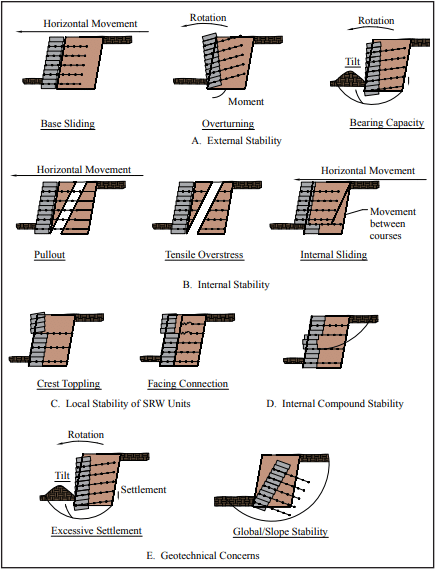
Stability analyses for geosynthetic reinforced SRW systems under static and seismic loading conditions involve separate calculations to establish factors of safety against external, internal, facing and internal compound modes of failure (Figure 1).

External stability calculations consider the reinforced soil zone and the facing column as a monolithic gravity structure. The evaluation of factors of safety against base sliding, overturning about the toe, and foundation bearing capacity is similar to that used for conventional reinforced concrete masonry gravity structures.

Internal stability analyses for geosynthetic reinforced soil walls are carried out to ensure that the structural integrity of the reinforced zone is preserved with respect to reinforcement over-stressing within the reinforced zone, pullout of geosynthetic reinforcement layers from the anchorage zone, and internal sliding along a reinforcement layer.

Facing stability analyses are carried out to ensure that the facing column is stable at all elevations and connections between the facing units and reinforcement layers are not over-stressed.

Internal compound stability analyzes the coherence of the block-geogrid system through potential compound slip circles that originate behind the soil-reinforced SRW and exit at the face of the wall.

Minimum recommended factors of safety (FS) of static and seismic design of geosynthetic reinforced SRW structures are given in Table 1. In general, FS for seismic design are taken as 75% of the values recommended for statically loaded structures following AASHTO/FHWA practice.

Potential concerns such as settlement of reinforced SRW structures due to compression, liquefaction, or squeezing of foundation soils is not considered here. Separate calculations for foundation-induced deformations may be required by the designer. In addition, slope instability involving volumes of soil beyond and below the base of the facing column is not considered. For global stability analysis, computer programs are available that consider the effects of both the stabilizing influence of reinforcement layers and destabilizing influence of seismic-induced ground acceleration (ref. 7).

EXTERNAL STABILITY

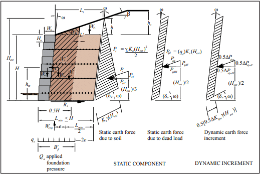
External stability calculations are similar to those for conventional static conditions, with the addition of the inertial force due to wall weight and the dynamic earth increment. Dynamic earth pressure, shown in Figure 2, is used to calculate the destabilizing forces in otherwise conventional expressions for the factor of safety against sliding along the foundation surface, overturning about the toe, and bearing capacity failure of the foundations soils. By convention, only half of the dynamic earth force increment is applied when calculating external seismic forces on conventional and reinforced SRWs. The simplified geometry and forces shown in Figure 2 are used in external stability calculations.

INTERNAL STABILITY

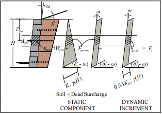
The contributory area approach (ref. 1, Sec. 7.5.2.2) used for the static stability analysis of SRWs is extended to the dynamic loading case (Figure 3). In this method, the reinforcement layers are modeled as tie-backs with the tensile force Fi in layer n equal to the earth pressure integrated over the contributory area Ac(n) at the back of the facing column plus the corresponding wall inertial force increment. Hence:

Fi(n) = khint ΔWw(n) + Fgsta(n) + Fdyn(n)

where:

khint ΔWw(n) = wall inertial force increment
Fgsta(n)           = static component of reinforcement load
Fdyn(n)            = dynamic component of reinforcement load.

Internal stability calculations are also similar to those carried out for conventional static conditions with the inclusion of dynamic earth pressure. For reinforced SRWs, full dynamic load is applied to internal stability with the exception of internal sliding that employs half ΔPdyn. Figure 3 shows the static and dynamic earth pressure distribution for internal stability calculations. The calculations for internal stability are presented in detail in Reference 1.

FACING STABILITY

Facing stability calculations are similar to those used for the static analysis with the addition of the dynamic load. To evaluate the connection strength, the connection capacity at each reinforcement elevation is compared to the tensile force Fi already determined. The crest toppling is evaluated, determining the static, inertial and dynamic forces acting on the unreinforced top blocks. Only half of the dynamic load ΔPdyn is used to mirror the external overturning analysis.

INTERNAL COMPOUND STABILITY

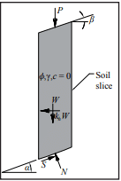
The consideration of seismic load for internal compound stability calculations is based on the addition of an inertial force (khW) associated with the mass of each soil slice (see Figure 4).

The incorporation of an additional dynamic load or inertial force is calculated as follows:

where:

di = vertical distance from the gravity center of the soil mass to the center of the slip surface
R = radius of the slip surface
Tavailable = available reinforcement force at the location of the intersection of the failure plane
Favailable = available facing force at failure plane exit.

FIELD PERFORMANCE

SRW performance during earthquakes is generally considered to be excellent (refs. 8, 9). Observations of SRWs within 31 miles (50 km) of the epicenter of both the Loma Prieta and Northridge earthquakes have shown that this type of retaining wall system can withstand considerable horizontal and vertical accelerations without experiencing unacceptable deformations. Similar to other structures subject to “near” maximum probable magnitude earthquakes, the designer should be aware that SRWs may need to be evaluated if damages are noticed, and repaired if necessary.

The design procedures presented in Design Manual for Segmental Retaining Walls, 3rd ed., provide a rational, detailed design methodology which, if followed, will allow designers to take advantage of SRW technology to build safe and economical retaining walls to withstand seismic forces.

REFERENCES

  1. Design Manual for Segmental Retaining Walls (Third Edition), Concrete Masonry & Hardscapes Association,
  2. SRWallv4, Concrete Masonry & Hardscapes Association
  3. Mechanically Stabilized Earth Walls and Reinforced Soil Slopes Design and Construction Guidelines, Elias, V., Christopher, B.R., and Berg, R.R., FHWA NHI-00-043,
  4. Standard Specifications for Highway Bridges, 17th AASHTO, 2002.
  5. Guide to Segmental Retaining Walls, SRW-TEC-005-09, Concrete Masonry & Hardscapes Association, 2009.
  6. Inspection Guide for Segmental Retaining Walls, SRW-TEC-008-12, Concrete Masonry & Hardscapes Association, 2010.
  7. Duncan, J.M., Low, B.K., and Shaeffer, V.R., STABGM: A Computer Program for Slope Stability Analysis of Reinforced Embankments, Virginia Polytechnic Institute,
  8. Field Observations of Reinforced Soil Structures Under Seismic Loading, Collin, G., Chouery-Curtis, V.E., and Berg, R. R., Proceedings International Symposium on Earth Reinforcement Practice, Fukuoka, Japan, 1992.
  9. Retaining Walls Stand Up to the Northridge Earthquake, Sandri, D., Geotechnical Fabrics Report 12 (4), 1994.
  10.  

Seismic Design and Detailing Requirements for Masonry Structures

INTRODUCTION

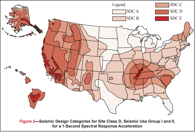
Historically, degree of seismic risk and the resulting design loads have been linked to seismic zones, with higher seismic zones associated with higher anticipated ground motion. More recently, design codes and standards (refs. 1, 2, 3) have replaced the use of seismic zones with Seismic Design Categories (SDCs). While seismic zones and design categories share similar concepts, there are also specific considerations that make each unique. The information that follows outlines the procedure for defining a project’s SDC, the permissible design methods that can be used with each SDC, and the prescriptive reinforcement associated with each SDC level.

This TEK is based on the requirements of the 2006 and 2009 editions of the International Building Code (IBC) (refs. 3a, 3b). While the applicable seismic provisions covered have not changed significantly over the last several code cycles, designers and contractors should be aware of several key revisions that have been introduced in recent years.

SEISMIC DESIGN CATEGORIES

SDCs range from SDC A (lowest seismic risk) through SDC F (highest seismic risk). Several factors contribute to defining the seismic design category for a particular project, including:

  • Maximum earthquake ground motion. Ground acceleration values are obtained from maps published in the IBC (ref. 3) or the ASCE 7 Minimum Design Loads for Buildings and Other Structures (ref. 2).
  • Local soil profile. Soil profiles are classified as Site Class A (hard rock) through Site Class F (organic or liquefiable soils). When the soil properties are not know in sufficient detail to determine the site class, Site Class D (moderately stiff soil) is assumed.
  • Use or occupancy hazard of the structure. Each structure is assigned to one of four unique Occupancy Categories corresponding to its use or hazard to life safety. Structures assigned to Occupancy Category I include those with a very low hazard to human life in the event of failure (including many agricultural buildings and minor storage facilities). Structures assigned to Occupancy Category III include those that would present a substantial public hazard including schools, jails, and structures with an occupancy load greater than 5,000. Structures assigned to Occupancy Category IV are designated essential facilities (such as hospitals and fire stations) and structures that contain substantial quantities of hazardous materials. Structures assigned to Occupancy Category II are those not included in any of the other three categories.

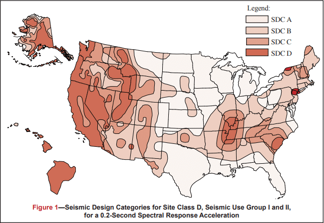
Figures 1 and 2 define the SDC for 0.2 and 1 second spectral response acceleration, respectively. Each figure is based on Site Class D (the default class when the soil profile is not known) and is applicable to structures assigned to Occupancy Categories I, II, and III (buildings other than high hazard exposure structures). Note that if the soil profile is known and is lower than D, a correspondingly lower SDC may be realized.

Structures are assigned to the highest SDC obtained from either Figure 1 or Figure 2. Alternatively, Section 1613.5.6.1 of the 2006 or 2009 IBC (refs. 3a, 3b) permits the SDC to be determined based solely on Figure 1 (0.2 second spectral response acceleration) for relatively short, squat structures (common for masonry buildings) meeting the requirements of that section. Table 1 may be used to apply Figures 1 and 2 to structures assigned to Occupancy Category IV.

DESIGN LIMITATIONS

Based on the assigned SDC, limitations are placed on the design methodology that is permitted to be used for the design of the seismic force-resisting system (i.e., the masonry shear walls).

Designers have the option of using several design methods for masonry structures: empirical design (ref. 4); allowable stress design (ref. 5); strength design (ref. 6); or prestressed masonry design (ref. 7), each of which is based on the provisions contained in the Masonry Standards Joint Committee Building Code Requirements for Masonry Structures (MSJC) (ref. 1). There are, however, restrictions placed on the use of both empirical design and unreinforced masonry, neither of which considers reinforcement, if present, as contributing to the structure’s strength or ductility. Table 2 summarizes the design procedures that may be used for each SDC.

Similarly, as the seismic risk/hazard increases, codes require more reinforcement to be incorporated into the structure. This reinforcement is prescriptively required as a minimum and is not a function of any level of determined loading on the structure. That is, design loads may require a specific reinforcement schedule to safely resist applied loads, which cannot be less than the minimum prescriptive seismic reinforcement triggered by the assigned SDC. For convenience, each level of prescriptive seismic reinforcement is given a unique name as summarized in Table 3.

The following discussion reviews in detail the seismic design requirements for loadbearing and nonloadbearing concrete masonry assemblies as required under the 2006 and 2009 IBC, which in turn reference the 2005 and 2008 MSJC, respectively. While many of the seismic design and detailing requirements between these two code editions are similar, there are unique differences that need to be considered when using one set of provisions over the other. The information presented covers the seismic design and detailing requirements for all concrete masonry construction with the exception of concrete masonry veneers, which is addressed in TEK 03-06C, Concrete Masonry Veneers (ref. 8).

The requirements listed below for each SDC and shear wall type are cumulative. That is, masonry assemblies in structures assigned to SDC B must meet the requirements for SDC A as well as those for SDC B. Buildings assigned to SDC C must meet the requirements for Categories A, B and C, and so on.

2006 IBC SEISMIC DESIGN AND DETAILING REQUIREMENTS

The seismic design and detailing provisions for masonry are invoked through Section 2106 of the IBC (ref. 3a), which in turn references the 2005 MSJC (ref. 1a). The IBC provisions detail a series of modifications and additions to the seismic requirements contained in the MSJC, which include:

  • IBC Section 2106.1 requires all masonry walls, regardless of SDC, not designed as part of the seismic force-resisting system (partition and nonloadbearing walls, eg.) to be structurally isolated, so that in-plane loads are not inadvertently imparted to them. The MSJC, conversely, requires isolation of such elements only for SDC C and higher.
  • IBC Section 2106.1.1 outlines minimum prescriptive detailing requirements for three prestressed masonry shear wall types: ordinary plain, intermediate, and special prestressed masonry shear walls. While the MSJC contains general design requirements for prestressed masonry systems, it does not contain prescriptive seismic requirements applicable to this design approach.
  • Anchorage requirements are addressed by Section 2106.2 of the IBC. Although analogous requirements are included in MSJC Section 1.14.3.3, the MSJC requirements are based on antiquated design loads that are no longer compatible with those of the IBC.
  • For structures assigned to SDC C and higher that include columns, pilasters and beams, and that are part of the seismic force-resisting system and support discontinuous masonry walls, IBC Section 2106.4.1 requires these elements to have a minimum transverse reinforcement ratio of 0.0015, with a maximum transverse reinforcement spacing of one-fourth the least nominal dimension for columns and pilasters and one-half the nominal depth for beams.
  • For structures assigned to SDC D and higher, IBC Section 2106.5 includes modifications that are an indirect means of attempting to increase the flexural ductility of elements that are part of the seismic force-resisting system. For elements designed by allowable stress design provisions (MSJC Chapter 2), in-plane shear and diagonal tension stresses are required to be increased by 50 percent. For elements designed by strength design provisions (MSJC Chapter 3) that are controlled by flexural limit states, the nominal shear strength at the base of a masonry shear wall is limited to the strength provided by the horizontal shear reinforcement in accordance with Eqn. 1.

Due to a shear capacity check in MSJC Section 3.1.3 that requires the nominal shear strength of a shear wall to equal or exceed the shear corresponding to the development of approximately 156% of the nominal flexural strength, Equation 1 controls except in cases where the nominal shear strength equals or exceeds 250% of the required shear strength. For such cases, the nominal shear strength is determined as a combination of the shear strength provided by the masonry and the shear reinforcement.

2005 MSJC Seismic Design and Detailing Requirements

The majority of the prescriptive seismic design and detailing requirements for masonry assemblies are invoked by reference to Section 1.14 of the 2005 MSJC. The following summarizes these requirements as they apply to concrete masonry construction.

Masonry Shear Wall Types

In addition to the prestressed masonry shear walls outlined by the IBC, the MSJC includes detailing requirements for six different shear wall options. A summary of these shear wall types follows. Table 3 summarizes the SDCs where each shear wall type may be used.

Empirically Designed Masonry Shear Walls—Masonry shear walls designed by the empirical design method (MSJC Chapter 5). Empirically designed masonry shear walls do not account for the contribution of reinforcement (if present) in determining the strength of the system.

Ordinary Plain (Unreinforced) Masonry Shear Walls—Ordinary plain masonry shear walls are designed as unreinforced elements, and as such rely entirely on the masonry to carry and distribute the anticipated loads. These shear walls do not require any prescriptive reinforcement. As such, they are limited to SDCs A and B.

Detailed Plain (Unreinforced) Masonry Shear Walls—Detailed plain masonry shear walls are also designed as unreinforced elements, however some prescriptive reinforcement is mandated by the MSJC to help ensure a minimum level of inelastic deformation capacity and energy dissipation in the event of an earthquake. As the anticipated seismic risk increases (which corresponds to higher SDCs), the amount of prescriptive reinforcement also increases. The minimum prescriptive reinforcement for detailed plain masonry shear walls is shown in Figure 3.

Ordinary Reinforced Masonry Shear Walls—Ordinary reinforced masonry shear walls, which are designed using reinforced masonry procedures, rely on the reinforcement to carry and distribute anticipated tensile stresses, and on the masonry to carry compressive stresses. Although such walls contain some reinforcement, the MSJC also mandates prescriptive reinforcement to ensure a minimum level of performance during a design level earthquake. The reinforcement required by design may also serve as the prescriptive reinforcement. The minimum prescriptive vertical and horizontal reinforcement requirements are identical to those for detailed plain masonry shear walls (see Figure 3).

Intermediate Reinforced Masonry Shear Walls—Intermediate reinforced masonry shear walls are designed using reinforced masonry design procedures. Intermediate reinforced shear wall reinforcement requirements differ from those for ordinary reinforced in that the maximum spacing of vertical reinforcement is reduced from 120 in. (3,048 mm) to 48 in. (1,219 mm) (see Figure 4).

Special Reinforced Masonry Shear Walls—Prescriptive reinforcement for special reinforced masonry shear walls must comply with the requirements for intermediate reinforced masonry shear walls and the following (see also Figure 5):

  • The sum of the cross-sectional area of horizontal and vertical reinforcement must be at least 0.002 times the gross cross- sectional wall area.
  • The cross-sectional reinforcement area in each direction must be at least 0.0007 times the gross cross-sectional wall area.
  • The vertical and horizontal reinforcement must be uniformly distributed.
  • The minimum cross-sectional area of vertical reinforcement must be one-third of the required horizontal reinforcement.
  • All horizontal reinforcement must be anchored around the vertical reinforcement with a standard hook.

The following additional requirements pertain to stack bond masonry shear walls assigned to SDC D, E or F. These walls must be constructed using fully grouted open-end units, fully grouted hollow units laid with full head joints, or solid units. The maximum reinforcement spacing for stack bond masonry shear walls assigned to SDC D is 24 in. (610 mm). For those assigned to SDC E or F, the cross-sectional area of horizontal reinforcement must be at least 0.0025 times the gross cross-sectional area of the masonry, and it must be spaced at 16 in. (406 mm) o.c., maximum.

Prescriptive Seismic Detailing for Nonloadbearing Elements

When incorporated into structures assigned to SDC C, D, E or F, masonry partition walls and other nonloadbearing masonry elements (i.e., those not designed to resist loads other than those induced by their own mass) must be isolated from the lateral force-resisting system. This helps ensure that forces are not inadvertently transferred from the structural to the nonstructural system. Nonstructural elements, such as partition walls, assigned to SDC C and above must be reinforced in either the horizontal or vertical direction (see Figure 6).

2009 IBC SEISMIC DESIGN AND DETAILING REQUIREMENTS

Unlike the 2006 IBC, the 2009 edition, which references the 2008 MSJC, contains no modifications to the seismic design and detailing provisions of the referenced standard. A summary of the substantive differences between the seismic design and detailing provisions of the 2005 and 2008 editions of the MSJC follows.

2008 MSJC Seismic Design and Detailing Requirements

The 2008 MSJC includes a comprehensive reorganization of the seismic design and detailing requirements intended to clarify the scope and intent of these provisions. In addition to the reorganization, several substantive changes applicable to concrete masonry construction have been incorporated, and these are detailed below. The prescriptive seismic detailing requirements for masonry shear walls remains substantially the same as under the 2005 MSJC and 2006 IBC.

Participating versus Nonparticipating Members—Elements of a masonry structure must now be explicitly classified either as participating in the seismic force-resisting system (for example, shear walls) or as nonparticipating members (for example, nonloadbearing partition walls). Elements designated as shear walls must satisfy the requirements for one of the designated shear wall types. Nonparticipating members must be appropriately isolated to prevent their inadvertent structural participation. This provision is similar in intent to the 2006 IBC requirement to isolate partition walls in SDC A and higher.

Connections—In previous editions of the MSJC, a minimum unfactored (service level) connection design force of 200 lb/ ft (2,919 N/m) was prescribed for all masonry shear wall assemblies except ordinary plain (unreinforced) masonry shear walls. In the 2008 MSJC, this minimum design load has been removed and replaced with a reference to the minimum loads prescribed by the adopted model building code. When the adopted model building code does not prescribe such loads, the requirements of ASCE 7 are to be used, which require a factored design force (strength level) of 280 lb/ft (4,087 N/m).

Story Drift—Due to the inherent stiffness of masonry structures, designers are no longer required to check the displacement of one story relative to adjacent stories for most masonry systems, simplifying the design process. Shear wall systems that are not exempted from checks for story drift include prestressed masonry shear walls and special reinforced masonry shear walls.

Stack Bond Prescriptive Detailing—Special reinforced masonry shear walls constructed of masonry laid in stack bond must now have a minimum area of horizontal reinforcement of 0.0015 times the gross cross-sectional wall area. This is an increase from the 0.0007 required in such walls in structures assigned to SDC D, and is a decrease from the 0.0025 required in such walls in structures assigned to SDC E and F by earlier editions of the MSJC.

Shear Capacity Check—In the 2005 MSJC, all masonry elements (both reinforced and unreinforced) designed by the strength design method were required to have a design shear strength exceeding the shear corresponding to the development of 125 percent of the nominal flexural strength, but need not be greater than 2.5 times the required shear strength. Because this provision is related primarily to the seismic performance of masonry structures, the 2008 MSJC requires it only for special reinforced masonry shear walls. Similarly, when designing special reinforced masonry shear walls by the allowable stress design method, the shear and diagonal tension stresses resulting from in-plane seismic forces are required to be increased by a factor of 1.5. Each of these checks is intended to increase flexural ductility while decreasing the potential for brittle shear failure.

Stiffness Distribution—In Chapter 1 of the 2008 MSJC, prescriptive seismic detailing requirements for masonry shear walls are related to an implicit level of inelastic ductile capacity. Because these detailing provisions apply primarily to shear walls, which in turn provide the principal lateral force-resistance mechanism for earthquake loads, the 2008 MSJC requires that the seismic lateral force-resisting system consist mainly of shear wall elements. At each story, and along each line of lateral resistance within a story, at least 80 percent of the lateral stiffness is required to be provided by shear walls. This requirement is intended to ensure that other elements, such as masonry piers and columns, do not contribute a significant amount of lateral stiffness to the system, which might in turn inadvertently change the seismic load distribution from that assumed in design. The 2008 MSJC does permit, however, the unlimited use of non-shear wall elements such as piers and columns provided that design seismic loads are determined using a seismic response modification factor, R, of 1.5 or less, consistent with the assumption of essentially elastic response to the design earthquake. In previous editions of the MSJC, these requirements were imposed only for masonry designed by the strength design method. In the 2008 MSJC, this requirement applies to all structures assigned to SDC C or higher.

Support of Discontinuous Elements—New to the 2008 MSJC, which was previously found in the 2006 IBC provisions, are the prescriptive detailing requirements for masonry columns, pilasters, and beams supporting discontinuous stiff elements that are part of the seismic force-resisting system. Such elements can impose actions from gravity loads, and also from seismic overturning, and therefore require that the columns, pilasters and beams supporting them have stricter prescriptive reinforcement requirements. These requirements apply only to structures assigned to SDC C and higher.

System Response Factors for Prestressed Masonry—In determining seismic base shear and story drift for structures whose seismic lateral force-resisting system consists of prestressed masonry shear walls, the value of the response modification coefficient, R, and of the deflection amplification factor, Cd, are required to be taken equal to those used for ordinary plain (unreinforced) masonry shear walls. The requirement previously existed as a recommendation in the MSJC Code Commentary. These values, as they apply to all types of masonry shear walls, are summarized in Table 4.

REFERENCES

  1. Building Code Requirements for Masonry Structures, Reported by the Masonry Standards Joint Committee.
    1. 2005 Edition: ACI 530-05/ASCE 5-05/TMS 402-05
    2. 2008 Edition: TMS 402-08/ACI 530-08/ASCE 5-08
  2. Minimum Design Loads for Buildings and Other Structures, ASCE 7-05. American Society of Civil Engineers, 2005.
  3. International Building Code. International Code Council.
    1. 2006 Edition
    2. 2009 Edition
  4. Empirical Design of Concrete Masonry Walls, TEK 14-08B. Concrete Masonry & Hardscapes Association, 2008.
  5. ASD of Concrete Masonry (2012 IBC & 2011 MSJC), TEK 14-07C, Concrete Masonry & Hardscapes Association, 2004.
  6. Strength Design of Concrete Masonry, TEK 14-04B. Concrete Masonry & Hardscapes Association, 2008.
  7. Post-Tensioned Concrete Masonry Wall Design, TEK 14-20A. Concrete Masonry & Hardscapes Association, 2002.
  8. Concrete Masonry Veneers, TEK 03-06C. Concrete Masonry & Hardscapes Association, 2012.

Concrete Masonry Screen Walls

INTRODUCTION

Concrete masonry screen walls are used in every part of every country on the globe, on every conceivable style of building, and for a wide variety of purposes. Created originally as a functional building element, the screen wall combines privacy with observation, interior light with shade and solar heat reduction, and airy comfort with wind control for both interior and exterior applications. Curtain walls, fences, sun screens, and room dividers are just a few of the limitless applications for a concrete masonry screen wall. The scope of this TEK focuses on the design and detailing of non-loadbearing concrete masonry screen walls. For loadbearing screen wall applications, users are referred to the applicable engineering analysis provisions of TMS 402 (Ref. 5).

Extra attention to the design of screen walls is warranted because of the relatively high percentage of open area in their face. The open area is created usually by the use of special screen units with decorative openings in their face. Screen walls should be designed to resist wind pressure and seismic forces to which they are exposed to while providing a durable and attractive architectural finish. Strength and stability is provided by: (1) incorporating steel reinforcement (either conventional reinforcing bars, bed joint reinforcement, and/or anchors); (2) limiting the clear span of screen walls; and/or (3) providing a separate support system capable of carrying lateral loads from the assembly to the backup support(s).

MATERIALS

Screen Wall Units – Due to the virtually limitless number of shapes and sizes for concrete masonry screen wall units, designers are encouraged to check on the availability of any specific shape during the early planning stages of a project. Some shapes are available only in certain localities and others may be restricted by patent or copyright. Figure 1 illustrates a general overview of some of the shapes that may be encountered for screen wall design. Note that these unit configurations can come in various thicknesses depending upon availability.

Despite screen wall units being used predominately in onloadbearing applications, they still should be of high quality for their intended construction. At a minimum, concrete masonry units used for screen walls should meet the requirements of ASTM C90, Standard Specification for Loadbearing Concrete Masonry (Ref. 1). Verification of unit properties should be in accordance with ASTM C140, Standard Test Methods for Sampling and Testing Concrete Masonry Units and Related Units, Annex A1 (Ref. 2). Due to their unique configuration full-size testing of screen wall block is not feasible, thus requiring that coupons be removed from the screen wall block for compressive strength testing. The coupon must meet the specimen size requirements of a height to thickness ratio equal to two (2) to one (1) and a length to thickness ratio equal to four (4) to one (1). In some situations, the length requirement for a specimen may not be able to be attained. In these cases, the length should be greater than or equal to the height of the specimen.

When tested in accordance with ASTM C140, screen units must attain a minimum average net area compressive strength of 2000 psi (13.7 MPa) based on three units tested. In addition to the above compressive strength requirements, the recommended minimum thickness of any part of the screen wall unit should not be less than 3/4 inches (19 mm).

Figure 2 presents a visual representation of where the coupon for a given screen block wall unit can be extracted. Per ASTM C140, the height of the coupon must be in the same orientation as the height of the screen block when it is placed.

Further information on ASTM C90, ASTM C140, and concrete masonry units can be found in CMU-TEC-001-23 (Ref. 7), TEK 18 01D (Ref. 16), and TEK 18-02C (Ref. 17).

Mortar – ASTM C270, Standard Specification for Mortar for Unit Masonry (Ref. 3), contains non-mandatory recommendations for the type of mortar to use for various applications. Type N mortar is the recommended type for exterior and interior nonloadbearing walls, which would encompass screen walls.

Alternatives such as Type S or M mortar can be used where the design variable or exposure conditions warrant.

For additional information on mortar, see TEK 09-01A (Ref. 9).

Grout – Grout for embedding steel reinforcement in horizontal or vertical cells should comply with ASTM C476, Standard Specification for Grout for Masonry (Ref. 4).

For additional information on grout, see TEK 09-04A (Ref. 10) and TEK 18-08A (Ref. 9).

Reinforcement and Anchor – Reinforcing steel comes in three different forms for screen walls: 1) Steel wire reinforcement that is prefabricated consisting of cold-drawn wire, 2) reinforcing bars, and 3) anchors. During the design, the designer must be cognizant of the cover and protective coating requirements for the steel. These requirements are largely dependent on the type of weather the screen wall will encounter during the life of the assembly and these requirements may affect the design of the wall.

For additional information on reinforcement steel, see TEK 12-01B (Ref. 12), TEK 12-02B (Ref. 13), TEK 12-04D (Ref. 14), and TEK 12-

06A (Ref. 15).

DESIGN

The design of a screen block wall depends upon a number of factors: function, location (exterior or interior), aesthetic requirements, and provisions of local building codes. They are used extensively for the following types of construction: (1) interior partitions, (2) free-standing walls supported on their own foundations, (3) and enclosed panels in masonry walls or external frames.

Screen wall partitions are designed as non-loadbearing panels with primary consideration given to adequate anchorage at panel ends and/or top edge, depending upon the type of lateral support furnished. Free-standing walls include such assemblies as fences and other exterior non-loadbearing screens that receive lateral stability from a structural frame braced to an adjacent structure or designed as a cantilever from the foundation.

Non-loadbearing screen walls should have a minimum nominal thickness of 4 in. (102 mm). Based on the nominal thickness of the unit and design method to be used, Table 1 was derived to determine the maximum height or length that can be built for a screen wall that has its units placed on a full mortar bed. This chart has been broken down into four separate distinct design categories: (1) Vertically Spanning per Allowable Stress Design (ASD) method, (2) Horizontally Spanning per Allowable Stress Design (ASD) method, (3) Vertically Spanning per Strength Design method, and (4) Horizontally Spanning per Strength Design method.

The use of Table 1 requires the following:

1) The tables assume the wall is either vertically spanning (supported at the top and bottom of the wall) or horizontally spanning and laid in a running bond (supported at the sides of the wall). If the wall is to be horizontally spanning using a bond pattern other than running bond, then the table is not valid and cannot be used.
2) The table assumes the screen wall units are placed on a full mortar bed with no open spaces between units.
3) The wind pressure and seismicity pressure expected to be encountered for the wall must be known.
4) The design pressure can be from either seismic or wind out-of place loading.
5) The screen walls are not designed to carry axial loads other than their own weight and are not part of the lateral force resisting system (shear walls).

Wind and seismic loads are typically the most frequently encountered external force that will interact with the wall. Wind pressures are calculated using the provisions ASCE 7, Minimum Design Loads for Buildings and Other Structures (Ref. 6) for open signs or lattice structures thus taking into account the open area of the screen wall. Seismic forces are also determined in accordance with ASCE 7 for architectural components based upon the installed weight of the screen wall. Based on the calculated loads, the designer should use the higher of the two loads to determine the maximum height to thickness or length to thickness ratio for a given design method.

For example, when building a horizontally spanning screen block wall with nominal 4 in. (102 mm) thick units placed with Type S portland cement mortar in an area that encounters 15 psf (0.718 kPa) wind pressure, the maximum length span of the screen wall is 12 ft (3.66 m) using the ASD method. Determined as follows:

Per Table 1a for a horizontally spanning wall,

Another example, when building a vertically spanning screen block wall with nominal 5 in. (127 mm) thick units placed with Type N portland cement mortar in an area that encounters 40 psf (1.915 kPa) wind pressure, the maximum height span of the screen wall is 6 ft 8 in. (2.03 m) using the Strength Design method. Determined as follows:

Per Table 1b for a vertically spanning wall,

Adequate anchorage should be provided between screen walls and lateral supports, and the supports should be designed to transfer loads to the structure and into the ground. Examples of anchorage of free-standing screens to their supporting framework is accomplished by various means as illustrated in Figure 3, with alternate support conditions shown in Figures 4, 5, 6, and 7. Lateral support may be obtained from cross walls, piers, columns, posts, or buttresses for horizontal spans, and from floors, foundations, roofs, or spandrel beams for screen walls spanning the vertical direction. Consideration should be given to expansion caused by temperature change and by deflection under load when screen wall panels are enclosed in a structural framing system.

CRACK CONTROL

The use of steel reinforcement is permitted where it can be embedded in mortar joints, in bond beam courses, or grouted into continuous vertical cells. Horizontal bed joint reinforcement consisting of two No. 9 gauge wires or equivalent, placed 16 inches o.c. is recommended when screen wall units are laid in stack bond. Horizontal bed joint reinforcement is not required for running bond masonry; however, the use of it helps with crack control in a masonry wall.

Ladder-type joint reinforcement and truss-type bed joint reinforcement are both acceptable forms of joint reinforcement as the reinforcement will lie on a solid face and not interfere with vertical reinforcement.

Control joints can be used at the discretion of the designer to mitigate cracking potential. Figures 6 and 7 illustrate options for supporting screen walls while incorporating control joints. For more information on crack control see, CMU-TEC-009-23 (Ref. 11).

REFERENCES

  1. Standard Specification for Loadbearing Concrete Masonry
    Units, ASTM C90-15. ASTM International, Inc., 2015.
  2. Standard Test Methods for Sampling and Testing Concrete
    Masonry Units and Related Units, ASTM C140-15. ASTM
    International, Inc., 2015.
  3. Standard Specification for Mortar for Unit Masonry, ASTM
    C270-14a. ASTM International, Inc., 2014.
  4. Standard Specification for Grout for Masonry, ASTM
    C476-10. ASTM International, Inc., 2010.
  5. Building Code Requirements for Masonry Structures, TMS
  6. The Masonry Society, 2016.
  7. Minimum Design Loads and Associated Criteria for
    Buildings and Other Structures, ASCE 7. American Society
    of Civil Engineers, 2016.
  8. Concrete Masonry Unit Shapes, Sizes, Properties, and
    Specifications, CMU-TEC-001-23, Concrete Masonry &
    Hardscapes Association, 2023.
  9. Grout Quality Assurance, TEK 18-08B, Concrete Masonry
    & Hardscapes Association, 2005.
  10. Mortars for Concrete Masonry, TEK 09-01A, Concrete
    Masonry & Hardscapes Association, 2004.
  11. Grout for Concrete Masonry, TEK 09-04A, Concrete
    Masonry & Hardscapes Association, 2005.
  12. Crack Control Strategies for Concrete Masonry
    Construction, CMU-TEC-009-23, Concrete Masonry &
    Hardscapes Association, 2023.
  13. Anchors and Ties for Masonry, TEK 12-01B, Concrete
    Masonry & Hardscapes Association, 2011.
  14. Joint Reinforcement for Concrete Masonry, TEK 12-02B,
    Concrete Masonry & Hardscapes Association, 2005.
  15. Steel Reinforcement for Concrete Masonry, TEK 12-04D,
    Concrete Masonry & Hardscapes Association, 2006.
  16. Splices, Development & Standard Hooks for Concrete
    Masonry Based on the 2009 & 2012 IBC, TEK 12-06A,
    Concrete Masonry & Hardscapes Association, 2013.
  17. Evaluating the Compressive Strength of Concrete
    Masonry, TEK 18-01D, Concrete Masonry & Hardscapes
    Association, 2017.
  18. Sampling and Testing Concrete Masonry Units, TEK 18-
    02C, Concrete Masonry & Hardscapes Association, 2014.