Resources

Seismic Design and Detailing Requirements for Masonry Structures

INTRODUCTION

Historically, degree of seismic risk and the resulting design loads have been linked to seismic zones, with higher seismic zones associated with higher anticipated ground motion. More recently, design codes and standards (refs. 1, 2, 3) have replaced the use of seismic zones with Seismic Design Categories (SDCs). While seismic zones and design categories share similar concepts, there are also specific considerations that make each unique. The information that follows outlines the procedure for defining a project’s SDC, the permissible design methods that can be used with each SDC, and the prescriptive reinforcement associated with each SDC level.

This TEK is based on the requirements of the 2006 and 2009 editions of the International Building Code (IBC) (refs. 3a, 3b). While the applicable seismic provisions covered have not changed significantly over the last several code cycles, designers and contractors should be aware of several key revisions that have been introduced in recent years.

SEISMIC DESIGN CATEGORIES

SDCs range from SDC A (lowest seismic risk) through SDC F (highest seismic risk). Several factors contribute to defining the seismic design category for a particular project, including:

  • Maximum earthquake ground motion. Ground acceleration values are obtained from maps published in the IBC (ref. 3) or the ASCE 7 Minimum Design Loads for Buildings and Other Structures (ref. 2).
  • Local soil profile. Soil profiles are classified as Site Class A (hard rock) through Site Class F (organic or liquefiable soils). When the soil properties are not know in sufficient detail to determine the site class, Site Class D (moderately stiff soil) is assumed.
  • Use or occupancy hazard of the structure. Each structure is assigned to one of four unique Occupancy Categories corresponding to its use or hazard to life safety. Structures assigned to Occupancy Category I include those with a very low hazard to human life in the event of failure (including many agricultural buildings and minor storage facilities). Structures assigned to Occupancy Category III include those that would present a substantial public hazard including schools, jails, and structures with an occupancy load greater than 5,000. Structures assigned to Occupancy Category IV are designated essential facilities (such as hospitals and fire stations) and structures that contain substantial quantities of hazardous materials. Structures assigned to Occupancy Category II are those not included in any of the other three categories.

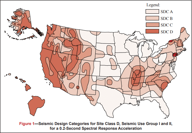
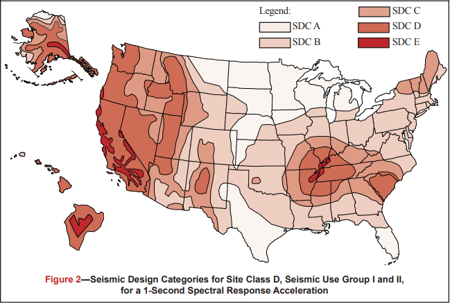
Figures 1 and 2 define the SDC for 0.2 and 1 second spectral response acceleration, respectively. Each figure is based on Site Class D (the default class when the soil profile is not known) and is applicable to structures assigned to Occupancy Categories I, II, and III (buildings other than high hazard exposure structures). Note that if the soil profile is known and is lower than D, a correspondingly lower SDC may be realized.

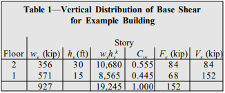
Structures are assigned to the highest SDC obtained from either Figure 1 or Figure 2. Alternatively, Section 1613.5.6.1 of the 2006 or 2009 IBC (refs. 3a, 3b) permits the SDC to be determined based solely on Figure 1 (0.2 second spectral response acceleration) for relatively short, squat structures (common for masonry buildings) meeting the requirements of that section. Table 1 may be used to apply Figures 1 and 2 to structures assigned to Occupancy Category IV.

DESIGN LIMITATIONS

Based on the assigned SDC, limitations are placed on the design methodology that is permitted to be used for the design of the seismic force-resisting system (i.e., the masonry shear walls).

Designers have the option of using several design methods for masonry structures: empirical design (ref. 4); allowable stress design (ref. 5); strength design (ref. 6); or prestressed masonry design (ref. 7), each of which is based on the provisions contained in the Masonry Standards Joint Committee Building Code Requirements for Masonry Structures (MSJC) (ref. 1). There are, however, restrictions placed on the use of both empirical design and unreinforced masonry, neither of which considers reinforcement, if present, as contributing to the structure’s strength or ductility. Table 2 summarizes the design procedures that may be used for each SDC.

Similarly, as the seismic risk/hazard increases, codes require more reinforcement to be incorporated into the structure. This reinforcement is prescriptively required as a minimum and is not a function of any level of determined loading on the structure. That is, design loads may require a specific reinforcement schedule to safely resist applied loads, which cannot be less than the minimum prescriptive seismic reinforcement triggered by the assigned SDC. For convenience, each level of prescriptive seismic reinforcement is given a unique name as summarized in Table 3.

The following discussion reviews in detail the seismic design requirements for loadbearing and nonloadbearing concrete masonry assemblies as required under the 2006 and 2009 IBC, which in turn reference the 2005 and 2008 MSJC, respectively. While many of the seismic design and detailing requirements between these two code editions are similar, there are unique differences that need to be considered when using one set of provisions over the other. The information presented covers the seismic design and detailing requirements for all concrete masonry construction with the exception of concrete masonry veneers, which is addressed in TEK 03-06C, Concrete Masonry Veneers (ref. 8).

The requirements listed below for each SDC and shear wall type are cumulative. That is, masonry assemblies in structures assigned to SDC B must meet the requirements for SDC A as well as those for SDC B. Buildings assigned to SDC C must meet the requirements for Categories A, B and C, and so on.

2006 IBC SEISMIC DESIGN AND DETAILING REQUIREMENTS

The seismic design and detailing provisions for masonry are invoked through Section 2106 of the IBC (ref. 3a), which in turn references the 2005 MSJC (ref. 1a). The IBC provisions detail a series of modifications and additions to the seismic requirements contained in the MSJC, which include:

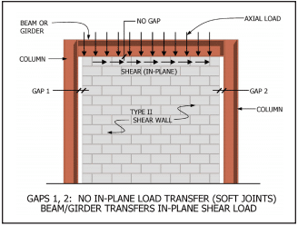
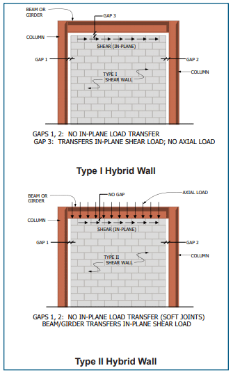
  • IBC Section 2106.1 requires all masonry walls, regardless of SDC, not designed as part of the seismic force-resisting system (partition and nonloadbearing walls, eg.) to be structurally isolated, so that in-plane loads are not inadvertently imparted to them. The MSJC, conversely, requires isolation of such elements only for SDC C and higher.
  • IBC Section 2106.1.1 outlines minimum prescriptive detailing requirements for three prestressed masonry shear wall types: ordinary plain, intermediate, and special prestressed masonry shear walls. While the MSJC contains general design requirements for prestressed masonry systems, it does not contain prescriptive seismic requirements applicable to this design approach.
  • Anchorage requirements are addressed by Section 2106.2 of the IBC. Although analogous requirements are included in MSJC Section 1.14.3.3, the MSJC requirements are based on antiquated design loads that are no longer compatible with those of the IBC.
  • For structures assigned to SDC C and higher that include columns, pilasters and beams, and that are part of the seismic force-resisting system and support discontinuous masonry walls, IBC Section 2106.4.1 requires these elements to have a minimum transverse reinforcement ratio of 0.0015, with a maximum transverse reinforcement spacing of one-fourth the least nominal dimension for columns and pilasters and one-half the nominal depth for beams.
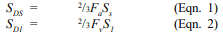
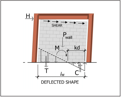
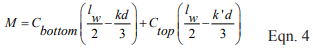
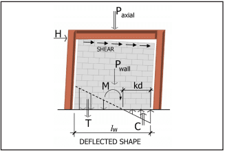
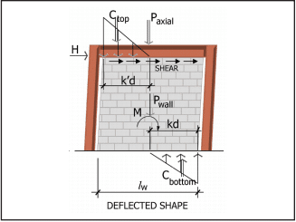
  • For structures assigned to SDC D and higher, IBC Section 2106.5 includes modifications that are an indirect means of attempting to increase the flexural ductility of elements that are part of the seismic force-resisting system. For elements designed by allowable stress design provisions (MSJC Chapter 2), in-plane shear and diagonal tension stresses are required to be increased by 50 percent. For elements designed by strength design provisions (MSJC Chapter 3) that are controlled by flexural limit states, the nominal shear strength at the base of a masonry shear wall is limited to the strength provided by the horizontal shear reinforcement in accordance with Eqn. 1.

Due to a shear capacity check in MSJC Section 3.1.3 that requires the nominal shear strength of a shear wall to equal or exceed the shear corresponding to the development of approximately 156% of the nominal flexural strength, Equation 1 controls except in cases where the nominal shear strength equals or exceeds 250% of the required shear strength. For such cases, the nominal shear strength is determined as a combination of the shear strength provided by the masonry and the shear reinforcement.

2005 MSJC Seismic Design and Detailing Requirements

The majority of the prescriptive seismic design and detailing requirements for masonry assemblies are invoked by reference to Section 1.14 of the 2005 MSJC. The following summarizes these requirements as they apply to concrete masonry construction.

Masonry Shear Wall Types

In addition to the prestressed masonry shear walls outlined by the IBC, the MSJC includes detailing requirements for six different shear wall options. A summary of these shear wall types follows. Table 3 summarizes the SDCs where each shear wall type may be used.

Empirically Designed Masonry Shear Walls—Masonry shear walls designed by the empirical design method (MSJC Chapter 5). Empirically designed masonry shear walls do not account for the contribution of reinforcement (if present) in determining the strength of the system.

Ordinary Plain (Unreinforced) Masonry Shear Walls—Ordinary plain masonry shear walls are designed as unreinforced elements, and as such rely entirely on the masonry to carry and distribute the anticipated loads. These shear walls do not require any prescriptive reinforcement. As such, they are limited to SDCs A and B.

Detailed Plain (Unreinforced) Masonry Shear Walls—Detailed plain masonry shear walls are also designed as unreinforced elements, however some prescriptive reinforcement is mandated by the MSJC to help ensure a minimum level of inelastic deformation capacity and energy dissipation in the event of an earthquake. As the anticipated seismic risk increases (which corresponds to higher SDCs), the amount of prescriptive reinforcement also increases. The minimum prescriptive reinforcement for detailed plain masonry shear walls is shown in Figure 3.

Ordinary Reinforced Masonry Shear Walls—Ordinary reinforced masonry shear walls, which are designed using reinforced masonry procedures, rely on the reinforcement to carry and distribute anticipated tensile stresses, and on the masonry to carry compressive stresses. Although such walls contain some reinforcement, the MSJC also mandates prescriptive reinforcement to ensure a minimum level of performance during a design level earthquake. The reinforcement required by design may also serve as the prescriptive reinforcement. The minimum prescriptive vertical and horizontal reinforcement requirements are identical to those for detailed plain masonry shear walls (see Figure 3).

Intermediate Reinforced Masonry Shear Walls—Intermediate reinforced masonry shear walls are designed using reinforced masonry design procedures. Intermediate reinforced shear wall reinforcement requirements differ from those for ordinary reinforced in that the maximum spacing of vertical reinforcement is reduced from 120 in. (3,048 mm) to 48 in. (1,219 mm) (see Figure 4).

Special Reinforced Masonry Shear Walls—Prescriptive reinforcement for special reinforced masonry shear walls must comply with the requirements for intermediate reinforced masonry shear walls and the following (see also Figure 5):

  • The sum of the cross-sectional area of horizontal and vertical reinforcement must be at least 0.002 times the gross cross- sectional wall area.
  • The cross-sectional reinforcement area in each direction must be at least 0.0007 times the gross cross-sectional wall area.
  • The vertical and horizontal reinforcement must be uniformly distributed.
  • The minimum cross-sectional area of vertical reinforcement must be one-third of the required horizontal reinforcement.
  • All horizontal reinforcement must be anchored around the vertical reinforcement with a standard hook.

The following additional requirements pertain to stack bond masonry shear walls assigned to SDC D, E or F. These walls must be constructed using fully grouted open-end units, fully grouted hollow units laid with full head joints, or solid units. The maximum reinforcement spacing for stack bond masonry shear walls assigned to SDC D is 24 in. (610 mm). For those assigned to SDC E or F, the cross-sectional area of horizontal reinforcement must be at least 0.0025 times the gross cross-sectional area of the masonry, and it must be spaced at 16 in. (406 mm) o.c., maximum.

Prescriptive Seismic Detailing for Nonloadbearing Elements

When incorporated into structures assigned to SDC C, D, E or F, masonry partition walls and other nonloadbearing masonry elements (i.e., those not designed to resist loads other than those induced by their own mass) must be isolated from the lateral force-resisting system. This helps ensure that forces are not inadvertently transferred from the structural to the nonstructural system. Nonstructural elements, such as partition walls, assigned to SDC C and above must be reinforced in either the horizontal or vertical direction (see Figure 6).

2009 IBC SEISMIC DESIGN AND DETAILING REQUIREMENTS

Unlike the 2006 IBC, the 2009 edition, which references the 2008 MSJC, contains no modifications to the seismic design and detailing provisions of the referenced standard. A summary of the substantive differences between the seismic design and detailing provisions of the 2005 and 2008 editions of the MSJC follows.

2008 MSJC Seismic Design and Detailing Requirements

The 2008 MSJC includes a comprehensive reorganization of the seismic design and detailing requirements intended to clarify the scope and intent of these provisions. In addition to the reorganization, several substantive changes applicable to concrete masonry construction have been incorporated, and these are detailed below. The prescriptive seismic detailing requirements for masonry shear walls remains substantially the same as under the 2005 MSJC and 2006 IBC.

Participating versus Nonparticipating Members—Elements of a masonry structure must now be explicitly classified either as participating in the seismic force-resisting system (for example, shear walls) or as nonparticipating members (for example, nonloadbearing partition walls). Elements designated as shear walls must satisfy the requirements for one of the designated shear wall types. Nonparticipating members must be appropriately isolated to prevent their inadvertent structural participation. This provision is similar in intent to the 2006 IBC requirement to isolate partition walls in SDC A and higher.

Connections—In previous editions of the MSJC, a minimum unfactored (service level) connection design force of 200 lb/ ft (2,919 N/m) was prescribed for all masonry shear wall assemblies except ordinary plain (unreinforced) masonry shear walls. In the 2008 MSJC, this minimum design load has been removed and replaced with a reference to the minimum loads prescribed by the adopted model building code. When the adopted model building code does not prescribe such loads, the requirements of ASCE 7 are to be used, which require a factored design force (strength level) of 280 lb/ft (4,087 N/m).

Story Drift—Due to the inherent stiffness of masonry structures, designers are no longer required to check the displacement of one story relative to adjacent stories for most masonry systems, simplifying the design process. Shear wall systems that are not exempted from checks for story drift include prestressed masonry shear walls and special reinforced masonry shear walls.

Stack Bond Prescriptive Detailing—Special reinforced masonry shear walls constructed of masonry laid in stack bond must now have a minimum area of horizontal reinforcement of 0.0015 times the gross cross-sectional wall area. This is an increase from the 0.0007 required in such walls in structures assigned to SDC D, and is a decrease from the 0.0025 required in such walls in structures assigned to SDC E and F by earlier editions of the MSJC.

Shear Capacity Check—In the 2005 MSJC, all masonry elements (both reinforced and unreinforced) designed by the strength design method were required to have a design shear strength exceeding the shear corresponding to the development of 125 percent of the nominal flexural strength, but need not be greater than 2.5 times the required shear strength. Because this provision is related primarily to the seismic performance of masonry structures, the 2008 MSJC requires it only for special reinforced masonry shear walls. Similarly, when designing special reinforced masonry shear walls by the allowable stress design method, the shear and diagonal tension stresses resulting from in-plane seismic forces are required to be increased by a factor of 1.5. Each of these checks is intended to increase flexural ductility while decreasing the potential for brittle shear failure.

Stiffness Distribution—In Chapter 1 of the 2008 MSJC, prescriptive seismic detailing requirements for masonry shear walls are related to an implicit level of inelastic ductile capacity. Because these detailing provisions apply primarily to shear walls, which in turn provide the principal lateral force-resistance mechanism for earthquake loads, the 2008 MSJC requires that the seismic lateral force-resisting system consist mainly of shear wall elements. At each story, and along each line of lateral resistance within a story, at least 80 percent of the lateral stiffness is required to be provided by shear walls. This requirement is intended to ensure that other elements, such as masonry piers and columns, do not contribute a significant amount of lateral stiffness to the system, which might in turn inadvertently change the seismic load distribution from that assumed in design. The 2008 MSJC does permit, however, the unlimited use of non-shear wall elements such as piers and columns provided that design seismic loads are determined using a seismic response modification factor, R, of 1.5 or less, consistent with the assumption of essentially elastic response to the design earthquake. In previous editions of the MSJC, these requirements were imposed only for masonry designed by the strength design method. In the 2008 MSJC, this requirement applies to all structures assigned to SDC C or higher.

Support of Discontinuous Elements—New to the 2008 MSJC, which was previously found in the 2006 IBC provisions, are the prescriptive detailing requirements for masonry columns, pilasters, and beams supporting discontinuous stiff elements that are part of the seismic force-resisting system. Such elements can impose actions from gravity loads, and also from seismic overturning, and therefore require that the columns, pilasters and beams supporting them have stricter prescriptive reinforcement requirements. These requirements apply only to structures assigned to SDC C and higher.

System Response Factors for Prestressed Masonry—In determining seismic base shear and story drift for structures whose seismic lateral force-resisting system consists of prestressed masonry shear walls, the value of the response modification coefficient, R, and of the deflection amplification factor, Cd, are required to be taken equal to those used for ordinary plain (unreinforced) masonry shear walls. The requirement previously existed as a recommendation in the MSJC Code Commentary. These values, as they apply to all types of masonry shear walls, are summarized in Table 4.

REFERENCES

  1. Building Code Requirements for Masonry Structures, Reported by the Masonry Standards Joint Committee.
    1. 2005 Edition: ACI 530-05/ASCE 5-05/TMS 402-05
    2. 2008 Edition: TMS 402-08/ACI 530-08/ASCE 5-08
  2. Minimum Design Loads for Buildings and Other Structures, ASCE 7-05. American Society of Civil Engineers, 2005.
  3. International Building Code. International Code Council.
    1. 2006 Edition
    2. 2009 Edition
  4. Empirical Design of Concrete Masonry Walls, TEK 14-08B. Concrete Masonry & Hardscapes Association, 2008.
  5. ASD of Concrete Masonry (2012 IBC & 2011 MSJC), TEK 14-07C, Concrete Masonry & Hardscapes Association, 2004.
  6. Strength Design of Concrete Masonry, TEK 14-04B. Concrete Masonry & Hardscapes Association, 2008.
  7. Post-Tensioned Concrete Masonry Wall Design, TEK 14-20A. Concrete Masonry & Hardscapes Association, 2002.
  8. Concrete Masonry Veneers, TEK 03-06C. Concrete Masonry & Hardscapes Association, 2012.

Seismic Design Forces on Concrete Masonry Buildings

INTRODUCTION

This TEK describes procedures for determining loads to be used when designing masonry buildings to resist earthquakes. The information provided herein is an overview of methods for determining the design ground motion, calculating the building base shear and distributing earthquake forces to lateral load resisting elements. Also reviewed are the earthquake forces on masonry walls when they are loaded out-of-plane.

With the merging of the model building codes used in various regions of the United States into the International Building Code (IBC, ref. 1), the trend in structural design is to refer to nationally approved standards for various aspects of design. The 2003 IBC references Minimum Design Loads for Buildings and Other Structures, ASCE 7-02 (ref. 2) for determining design loads, including earthquake loads, on structures. This TEK does not address the seismic design of non-building masonry structures. TEK 14-18B (ref. 3) covers prescriptive seismic reinforcement requirements for masonry structures.

LOAD DETERMINATION

Determination of Design Ground Motion

The first step in obtaining the seismic design forces on masonry buildings is to determine the maximum earthquake intensity that the building must be designed to resist. Since the risk of earthquakes occurring and the intensity of ground shaking that may take place varies over the United States, the seismic design force varies with the building location. ASCE 7 addresses this issue by defining a design earthquake for all regions in the United States. The design earthquake is two thirds of the maximum considered earthquake, which is the ground motion that causes the most severe effects considered by the code. In most parts of the United States, the maximum considered earthquake corresponds to a ground motion with a 2 percent chance of being exceeded in fifty years. While more intense ground shaking may occur in these regions, it is generally considered uneconomical to design for such uncommon earthquakes. In regions of high seismicity, however, such as California, the maximum considered earthquake is based on the characteristic magnitudes of earthquakes on known active faults. Since these faults can produce characteristic earthquakes every few hundred years, the ground motion corresponding to a 2 percent chance of being exceeded in 50 years will be significantly larger than the ground motion and structural periods corresponding to large magnitude earthquakes on known faults. Therefore, the maximum considered earthquake in regions of high seismicity is typically a deterministic ground motion based on the known characteristics of nearby faults.

For design purposes, ASCE 7 represents earthquake intensity by means of acceleration response spectra, as shown in Figure 1. Modeling of the ground motion in this manner provides structure-dependent information on the ground motion because buildings respond differently depending on their dynamic characteristics. ASCE 7 contains maps that provide spectral response acceleration values for the maximum considered earthquake ground motion for short period (0.2- second), Ss, and long period (1-second), S1, responses for the entire United States. The design earthquake, in turn, corresponds to two-thirds of the maximum considered earthquake. The spectral response values used for design are then given by:

The site class coefficients, Fa and Fv, depend on the soil properties at the site. ASCE 7 identifies six site classes (A through F) based on soil properties. The mapped spectral are given for Site Class B and modifications must be made to obtain the values for other site classes. Site classification is typically determined by a professional geotechnical engineer at the beginning of a project. However, if the soil properties are not known in sufficient detail to determine the site class, Class D may be used if approved by the building official. Figure 1 shows how the design response spectrum is obtained from the spectral response parameters.

Seismic Base Shear

The seismic base shear is the total design lateral force at the base of a building. The base shear is calculated using the design ground motion described in the previous section and modified to account for the structural characteristics and importance placed on a building.

ASCE 7 provides several structural analysis methods for calculating the seismic base shear. This TEK discusses the equivalent lateral force procedure, which is the most commonly used technique for seismic analyses. The equivalent lateral force procedure is a linear static analysis technique that approximates nonlinear building response by use of the response modification factor R, which accounts for a building’s inherent ductility and overstrength. ASCE 7 permits the use of the equivalent lateral force procedure for the design of most buildings, except for those with certain irregularities and buildings with periods greater than 3.5 seconds, such as high-rise buildings. ASCE 7 Table 9.5.2.2 provides values of R for various masonry structural systems. The seismic base shear is given by the following equation:

but need not be greater than

The occupancy importance factor, I, is used to ensure that larger forces are used to design buildings for which the consequences of failure may be more severe.

Equations 3 and 4 represent the base shear obtained from the design response spectrum shown in Figure 1, divided by the response modification factor. In addition to these equations, ASCE 7 also stipulates that the design base shear should not be less than:

or, for buildings and structures in Seismic Design Categories E and F, less than:

Vertical Distribution of Seismic Base Shear

When performing equivalent lateral force analysis, the earthquake load is distributed vertically over the height of the building by applying a portion of the seismic base shear to each level of the building, consistent with the assumption of concentrated floor masses. The force at each level, Fx is given by:

where: k = 1 for T ≤ 0.5 seconds; k = 2 for T ≥ 2.5 seconds. Linear interpolation is used for determining k between 1 and 2 for 0.5 < T < 2.5.

Horizontal Distribution of Seismic Base Shear

Once the seismic force at each floor has been determined from Equation 7, the story shear must be distributed to the lateral load resisting elements at each story. This varies depending on whether the diaphragm is rigid or flexible when compared to the stiffness of the lateral load resisting element. Masonry elements are typically quite stiff and conventional practice is to assume that wood floors and roofs or steel decks without concrete topping are flexible diaphragms. Conversely, concrete and hollow core slabs or steel decks with concrete topping are considered rigid diaphragms.

Figure 2 shows the difference in response of buildings with flexible diaphragms and buildings with rigid diaphragms. With flexible diaphragms, the force is distributed in proportion to the tributary area supported by each wall, whereas the rigid diaphragms distribute the force in proportion to wall stiffness.

Earthquake Loads on Components and Connections

When masonry walls are loaded out-of-plane they act as elements of the structure, or components, that resist the earthquake loads generated by their self-weight. For satisfactory structural response, the wall must span between supports and transfer lateral loads to the floor or roof diaphragm, which in turn transfers the loads to the lateral load resisting system.

Out-of-plane earthquake loads on masonry walls and their connections are calculated using the requirements of ASCE 7 for components. The following equation is used to determine the seismic design force Fp on the wall, which is distributed relative to the wall mass distribution:

The seismic force need not exceed

and should not be less than

Figure 3 shows the distribution of earthquake forces over the height of a building when calculated using Equation 8. Since the wall is supported at the bottom and top of each story, the average of the forces calculated for the floor above and the floor below is used to design walls in each story. This ensures that the earthquake forces are applied in proportion to the mass distribution of the wall.

Since earthquake ground motion is cyclic, walls should be evaluated for the out-of-plane demands in both directions to determine the most critical condition. The most severe condition usually occurs when the earthquake loads are applied outward since the eccentricity of the gravity loads from a roof or floor adds to the earthquake induced-moment. In addition, walls should be evaluated for all applicable load combinations in ASCE 7, including load combinations in which the vertical component of the ground motion is negative. This combination usually results in the smallest axial load on a wall and is important to consider since wall capacity and response can be dependent on axial load.

EXAMPLE

Calculate the following earthquake loads on the two-story building constructed with special reinforced masonry shear walls shown in Figure 4:

  1. earthquake load on the seismic force resisting system, and
  2. out-of-plane earthquake load on a typical second story wall.

The building is located at a site with Ss = 1.2g and S1 = 0.4g (SDC D). The building’s occupancy importance factor and component importance factor are equal to 1.0. The site classification for the project is D.

Solution a) earthquake load on the seismic force resisting system

  1. Seismic Weight
    The portion of the total gravity load of the structure located at the roof and second story is:
    wroof = 356 kip (1,584 kN)
    w2 = 571 kip (2,540 kN)
    The effective seismic weight of the building includes the total dead load plus any other code-prescribed loads. The total effective seismic weight, W, is:
    W = 356 + 571 = 927 kip (4,124 kN)
  2. Fundamental Period of Vibration
    In lieu of calculating the building period using a computer analysis, ASCE 7 permits the use of an approximate fundamental period using the following equation:
    Ta = Cthny
    The parameters Ct and y are equal to 0.02 and 0.75, respectively, for masonry buildings. Thus,
  1. Seismic Base Shear
    From ASCE 7 Tables 9.4.1.2.4a and Table 9.4.1.2.4b, Fa =1.02, Fv =1.6. Therefore,
    SDS = ⅔Fa</sub> Ss = 2/3(1.02)(1.2) = 0.82g
    SD1 = ⅔Fv S1 = 2/3(1.6)(0.4) = 0.43gThe seismic base shear is equal to

but need not be greater than

The design base shear should not be less than:
V = 0.044SDSIW = 0.044(0.82)(1.0)(927) = 33 kip (147 kN)

  1. Vertical Distribution of Seismic Base Shear
    The force at each level, Fx is given by:

Where k = 1.0 since T = 0.26 seconds, which is less than 0.5 seconds. Table 1 provides the vertical distribution of base shear to the floors of the building. Figure 5 shows the story shear and overturning moment at each floor of the building. At the second story, the steel deck is assumed to act as a flexible diaphragm and the story shear will be distributed to each wall based on the tributary area it supports. The second floor diaphragm with concrete topping is assumed to act as a rigid diaphragm and distributes the earthquake load to the walls in proportion to their stiffness. The engineer should confirm these assumptions by comparing the in-plane deflection of the diaphragms to the lateral displacement of the walls.

Solution b) out-of-plane earthquake load on a typical second story wall

From Equation 8, the out-of-plane seismic pressure attachment at the wall attachment point at the second floor is equal to:

which is less than the maximum pressure of:

and greater than the minimum pressure which is given by:

The pressure at the roof is equal to:

Since the earthquake pressure should be distributed uniformly over the height of the wall in proportion to the wall distribution of mass, the uniformly distributed earthquake pressure in the wall for the second story is equal to:

For the first story, the pressure at the wall attachment point at the ground level is:

Because this is less than the minimum pressure of 21 psf (1,005 Pa) from Equation 8b, use an average of 21 psf (1,005 Pa) at the ground level and 22 psf (1,053 Pa) previously calculated for the attachment point at the second level:

Fp = (21 + 22)/2 = 22 psf (1,053 Pa)

Figure 6 shows the out-of-plane earthquake forces on the masonry walls. Note that the load on the unbraced parapet is calculated using an amplification factor, ap of 2.5.

NOTATIONS

ap      amplification factor that represents the dynamic p amplification of the wall relative to the fundamental period of the structure. For most masonry walls, ap = 1.0, except for parapets and unbraced walls for which ap = 2.5.
Ct      building period coefficient
Cvx    vertical distribution factor
Fa     acceleration-based site class modification factor at short periods (0.2 second)
Fv     velocity-based site class modification factor at long periods (1-second)
Fp     seismic design force on the wall, psf (kPa)
Fx     force at each level, kip (kN)
h       average roof height of structure with respect to the base, ft (m)
hi      height from the base to level i, ft (m)
hn      height from the base to the highest level of the structure, ft (m)
hx      height from the base to level x , ft (m)
I        occupancy importance factor
Ip      component importance factor that varies from 1.0 to 1.5
k        an exponent related to the structure period: k = 1 for T ≤ 0.5 sec; k = 2 for T ≥ 2.5 sec; use linear interpolation to determine k for 0.5 < T < 2.5
N      number of stories in a structure
R      response modification factor per ASCE 7 Table 9.5.2.2
Rp     response modification factor that represents the wall overstrength and ductility or energy absorbing capability. For reinforced masonry walls, Rp = 2.5 while for unreinforced masonry walls, Rp = 1.5.
Sa      spectral response acceleration
Ss      5 percent damped, maximum considered earthquake spectral response acceleration at short periods (0.2- second)
S1       5 percent damped, maximum considered earthquake spectral response acceleration at long periods (1-second)
SDS    5 percent damped, design spectral response acceleration at short periods (0.2-second)
SD1    5 percent damped, design spectral response acceleration at long periods (1-second)
T       fundamental period of the structure, sec
Ta     approximate fundamental period of the structure, sec
V       seismic base shear, kip (kN)
W     effective seismic weight, kip (kN)
Wp    wall weight, psf (kPa)
wi     portion of building effective seismic weight W located at or assigned to level i
wx    portion of building effective seismic weight W located at or assigned to level x
y       building period exponent
z       height of point of wall attachment with respect to the base, ft (m)

REFERENCES

  1. International Code Council (ICC), 2003 International Building Code, International Code Council, Inc., 2002.
  2. Minimum Design Loads for Buildings and Other Structures, ASCE-7-02. American Society of Civil Engineers, 2002.
  3. Prescriptive Seismic Reinforcement Requirements for Masonry Structures, TEK 14-18B. Concrete Masonry & Hardscapes Association, 2003.


Hybrid Concrete Masonry Design

INTRODUCTION

Hybrid masonry is a structural system that utilizes reinforced masonry infill walls with a framed structure. While the frame can be constructed of reinforced concrete or structural steel, the discussion here will include steel frames in combination with reinforced concrete masonry walls. The masonry walls are used as part of the lateral load resisting system.

Following the development of the wrought iron framed Glass Palace in France in 1851, framed technology evolved and spread to the United States. Since then, combining masonry walls with frames has been used as a common feature of many early building types.

Caged construction was introduced in 1882 by architect George Post. The first caged framed building used a structural steel framework mixed with exterior walls of unreinforced masonry. The term caged walls resulted from the exterior walls being built around a structural cage. The frame supported the floor and roof gravity loads; the masonry was independent of the frame and self-supporting and provided the lateral stiffness. As a result, the wall thicknesses were only slightly less than those in bearing wall buildings.

Another type of structure used exterior unreinforced bearing walls and interior structural frames. The famous Monadnock Building in Chicago, constructed in 1892 is an example of this type with exterior masonry bearing walls up to 6 ft (1.83 m) thick. The 15-story building was the largest office building in the world when completed. Ironically, it was the last high-rise built with exterior masonry bearing walls for the full height of the building and an interior frame.

Transitional buildings were perhaps the most used type of combination frame/masonry structures used through the 1940s. An example is the 13-story Tower Building in New York built in 1888, which used transitional and load bearing construction. Transitional buildings took traditional masonry walls and constructed them integrally with the exterior structural frame. Brick or hollow clay tile was used as an inner wythe, usually 8 in. (203 mm) thick. An exterior wythe of brick, cast stone, terra-cotta or stone was anchored or headered to the backup to function as a composite wall system, but there was no accommodation for the masonry walls to take differential movement. It was common to design these buildings for gravity loads only. While the wall system was not intended to be structural, it provided lateral stiffness. The masonry also provided exterior finish, fire protection for the frame, and backup for the interior finish.

Confined masonry within concrete frames is yet another form of combination structure. This system originated in the 1800s. It has developed globally but apparently has no specific origin. Confined masonry is used primarily for residential construction. The type of masonry infill varies by region or country and includes clay brick, clay tile, stone or concrete masonry.

As framed structures grew taller, architects tried to reduce the thickness of the exterior walls. The structural steel and reinforced concrete structures were used to support building loads and exterior wall loads. Curtain walls and cavity walls developed during this time and masonry was no longer the only wall material used as a backup system for exterior walls.

The concept of using masonry infill to resist lateral forces is not new; having been used successfully throughout the world in different forms. While common worldwide, U.S. based codes and standards have lagged behind in the establishment of standardized means of designing masonry infill.

The hybrid masonry system outlined in this TEK is a unique method of utilizing masonry infill to resist lateral forces. The novelty of the hybrid masonry design approach relative to other more established infill design procedures is in the connection detailing between the masonry and the steel frame, which offers multiple alternative means of transferring loads into the masonry—or isolating the masonry infill from the frame.

Prior to implementing the design procedures outlined in this TEK, users are strongly urged to become familiar with the hybrid masonry concept, its modeling assumptions, and its limitations particularly in the way in which inelastic loads are distributed during earthquakes throughout the masonry and frame system. This system, or design methods, should not be used in Seismic Design Category D and above until further studies and tests have been performed; and additional design guidance is outlined in adopted codes and standards.

HYBRID MASONRY CONCEPT

Since the 1950s, architects and engineers have primarily used cavity walls with framed structures. The backup masonry walls are generally termed infill walls. They support out-of-plane loads on the wall and are isolated from the frame so as not to participate in the lateral load resistance (see Figure 1). Codes usually require that these walls be isolated from the lateral movement of the frame to ensure that lateral loads are not imparted to the masonry.

The hybrid system is a variation of the confined masonry system. It incorporates the beneficial qualities of transitional buildings and the characteristics of cavity wall construction. It differs from cavity wall construction in that the infill masonry walls participate with the frame and provide strength and stiffness to the system. The masonry can be used as single wythe or as cavity wall construction. Hybrid masonry structures are constructed of reinforced masonry, not unreinforced masonry, as was common in transitional buildings.

Hybrid masonry/framed structures were first proposed in print in 2006 (ref. 1). There are several primary reasons for its development. One reason is to simplify the construction of framed buildings with masonry infill. While many designers prefer masonry infill walls as the backup for veneers in framed buildings, there is often a conflict created when steel bracing is required and positioned such that conflicts arise with the masonry infill. This leads to detailing difficulties and construction interferences in trying to fit masonry around the braces. One solution is to eliminate the steel bracing and use reinforced masonry infill as shear wall and bracing.

Hybrid masonry/steel structures also provide structural redundancy that can be utilized to limit progressive collapse. The reinforced masonry infill provides an alternative load path for the frame’s gravity loads, hence providing redundancy. The resulting system is more efficient than either a frame or a bearing wall system alone when subjected to progressive collapse design conditions. If a steel column is damaged in a hybrid structure, gravity loads will transfer to the reinforced masonry. If the masonry is damaged, the gravity load transfers to the frame. There are documented examples from the World Trade Center disaster that illustrate redundancy in transitional buildings (ref. 2).

CLASSIFICATION OF WALLS

There are three hybrid wall types. The loadings these walls can support is dependent upon the degree of confinement of the masonry within the frame. These walls can potentially transfer axial loads from the beam/girder of the frame as well as transfer shear from the beam/girder or the columns. The wall systems are defined in Table 1 based on their ability to transfer loads from the frame to the wall. All wall systems listed can address the backup for cavity wall construction. If a veneer is used, it is constructed with relieving angles and is isolated for differential movement as with conventional cavity wall construction. By comparison, an infill wall used in a cavity wall does not transfer axial load or in-plane shear.

The following sections describe each wall type. The key to the performance of the walls is the confinement at the columns and the top of the wall along with the anchorage.

Type I Hybrid Walls

This wall type transmits out-of-plane loads and in-plane shear loads (Figure 1). The gap at the top and the top anchors should not transmit axial loads. If column anchors are used, they should not transmit shear loads. The gaps at the columns must be adequate so the columns do not bear against the masonry when the frame undergoes drift.

All wall types must transfer shear at the base of the wall. This is commonly done using dowels into the foundation or on the framing at the bottom of the wall.

The tie-down forces are a key component to the support of the wall against preventing overturning.

Effectively, the masonry wall is a nonloadbearing shear wall that also supports out-of-plane loads. The in-plane forces are shown in Figure 2. These forces must be applied to the frame design. The tension load T can be accommodated by the distributed reinforcement or the designated tie-down reinforcement. This same reinforcement can be used to distribute shear forces as well. Type I walls can be ideal for buildings up to four stories.

The forces are resolved into:

where e is the eccentricity of the tie-down force, which is defined as the distance between the tie-down reinforcement and the center of the wall.

Type II Hybrid Walls

The Type II hybrid wall is a modification of Type I. It is constructed tight to the beam framing above such that axial loads are transmitted to the masonry wall (Figure 3). The top anchors transmit out-of-plane loads and shear loads. If column anchors are used, they do not transmit shear loads.

Effectively, the masonry wall is a loadbearing shear wall that also supports out-of-plane loads.

There are two options for distributing the in-plane forces resulting from overturning of the shear wall, designated Type IIa and Type IIb. For Type IIa (Figure 4), the tension load T can be accommodated by the distributed reinforcement or the designated tie-down reinforcement. For Type IIb (Figure 5), the tension force that tied down the wall in the Type IIa wall is replaced by compression on the upper framing and is transferred into the steel frame. This is a significant benefit in multi-story buildings because the tie-down to the frame is not required.

As previously noted, shear dowels are needed at the base of the walls. Type IIb walls, unlike Type I and IIa, do not require tension lap splices for the vertical reinforcement at the base of the walls since only shear loads are being developed.

Type II walls are generally limited to buildings 10 to 14 stories high since masonry stresses will usually govern. Generally, this limitation is similar for loadbearing buildings as well.

The designer has the option to load-share the gravity loads with the masonry wall. This can reduce the size of the beam/girder framing member. For example, if the masonry is constructed after the dead loads of the floor/roof framing system are installed, the masonry wall can take the gravity loads that are added to the structure after the walls are built. The framing (columns and beams/girders) sizes can be limited to support only the dead loads and the lateral load effects. The framing should be designed for the full gravity loads if there is a chance that the wall will be modified in the future.

For the Type IIb wall at the base of the wall:

The overturning is resolved by:

The axial load imparted to the wall is a function of the construction sequence. This should be stated in the construction documents. For example, if the steel is designed for only the slab and framing dead load and the lateral load effects, the masonry walls must be constructed tight to the framing above after the slab is in place but before the wall above is started.

The steel framing and the masonry must be designed using similar assumptions.

Type III Hybrid Walls

This wall type is fully confined within the framing (Figure 6). It is most similar to the transitional buildings from the early 1900s. However, in this modernized version the masonry is engineered and reinforced to support axial and shear loads in addition to the out-of-plane loads. As with the Type II hybrid wall, the designer has the option to design the columns and beams/girders for the portion of the gravity loads installed before the masonry.

Currently, there are no standards in the United States that govern the design of this type of wall. Research is underway to help define the behavior of these walls, which will lead to code requirements. Designers should only use this system at their own discretion. Statics can be used to generate formulas comparable to Equations 1 through 4 for Type I and II hybrid.

Figures 7 and 8 show the two variations (Type IIIa and Type IIIb) based on how the overturning force is handled.

HYBRID DESIGN

As discussed, the masonry in hybrid structures can carry out-of-plane loads in addition to in-plane loads. The masonry design can be performed based on the code for reinforced masonry using allowable stress (based on linear elastic methods). As strength design procedures gain acceptance, load factor design with non-linear elastic evaluation of the masonry will be possible.

While there are three hybrid types that dictate the loadings (Type I, II and III), there are three shear wall types available for the design of the walls themselves. The shear wall type depends on the minimum prescriptive reinforcement and grouting. The Building Code Requirements for Masonry Structures and the International Building Code (IBC) (refs. 3, 4) classify shear walls as ordinary reinforced, intermediate reinforced, or special reinforced. Therefore, there are three combinations of hybrid types to choose from.

The structural steel system design and the in-plane loads to the masonry are based upon the IBC and ASCE 7 (ref. 11) using seismic factors for R (response modification coefficient), Ωo (system over-strength factor), and Cd (deflection amplification factor) applicable to the type of shear walls used with building frames. These factors are given in Table 2. An on-going research project at the University of Illinois is evaluating these factors for their applicability to hybrid walls.

Ordinary reinforced shear walls are permitted in Seismic Design Categories (SDCs) A, B and C. The building height is unlimited for SDCs A and B and limited to 160 ft (48.76 m) for SDC C.

Intermediate reinforced shear walls are permitted in SDCs A, B and C. The building height is unlimited.

Special reinforced shear walls are permitted in all seismic design categories. The building height is unlimited in SDCs A, B and C, limited to 160 ft (48.8 m) in SDCs D and E, and limited to 100 ft (30.5 m) in SDC F.

While these are the permitted types and classes, most projects thus far have been in SDC A, B and C. This has been convenient in that an R = 3 type structural steel design has been used in accordance with AISC. Designs in SDC D and higher would require use of the AISC Seismic Design Manual, AISC 327-05 (ref. 9). In addition, research is on-going for various aspects of the systems in higher seismic classes.

More detailed information on prescriptive seismic detailing for concrete masonry shear walls can be found in TEK 14-18A, Prescriptive Seismic Reinforcement Requirements for Masonry Structures (ref. 10).

COMPUTER SOFTWARE

Several commercial software companies have masonry design packages (refs. 5, 6), some of which have included hybrid masonry in their packages. This allows the masonry and steel to be modeled and designed as a system. The software is primarily based on allowable stress design and linear elastic analysis. There are plans to incorporate strength design in the future.

CONCLUSIONS

Hybrid masonry offers many benefits and complements framed construction. By using the masonry as a structural element for in-plane loads, the constructability of the masonry with the frames is improved, the lateral stiffness is increased, the redundancy is improved, and opportunities for reduced construction costs are created.

Designs indicate that greater stiffness can be achieved with hybrid masonry systems in comparison with braced frames or moment frames. The beneficial effect on the framing through the load-sharing abilities of the system is also evident. These qualities, stiffness, and redundancy can be useful in preventing progressive collapse.

For now, Type I and Type II hybrid systems can be designed in the United States using existing codes and standards. Criteria for Type III hybrid systems are under development.

Details for the construction of hybrid walls and design issues related to the top connectors are discussed in TEK 03-03B and IMI Technology Brief 02.13.02 (refs. 7, 8).

NOTATIONS:

C            = resultant compressive force, lb (N)
Cbottom  = resultant compressive force at bottom of masonry wall, lb (N)
Cd          = deflection amplification factor
Cleft        = resultant compressive force on left side of masonry wall, lb (N)
Cright      = resultant compressive force on right side of masonry wall, lb (N)
Ctop         = resultant compressive force at top of masonry wall, lb (N)
d              = distance from extreme compression fiber to centroid of tension reinforcement, in. (mm)
e              = eccentricity of the tie-down force, equal to the distance of the tie-down reinforcement from the center of the wall, in. (mm)
H            = shear force, lb (N)
h             = effective height of masonry element, in. (mm)
k, k’        = ratio of distance between compression face of wall and neutral axis to the effective depth, d for the bottom and top of the wall; and to the height of the wall, h, for the sides, respectively.
lw           = length of entire wall or of segment of wall considered in the direction of shear force, in. (mm)
M           = maximum moment at the section under consideration, in.-lb (N-mm)
Paxial     = axial load, lb (N)
Pwall      = axial load due to wall weight, lb (N)
R            = seismic response modification factor
T            = tension in reinforcement, lb (N)
Ωo          = system over-strength factor

REFERENCES

  1. Biggs, D.T., Hybrid Masonry Structures, Proceedings of the Tenth North American Masonry Conference, The Masonry Society, June 2007.
  2. Biggs, D.T., Masonry Aspects of the World Trade Center Disaster, The Masonry Society, 2004.
  3. Building Code Requirements for Masonry Structures, ACI 530-08/ASCE 5-08/TMS 402-08. The Masonry Society, 2008.
  4. 2006 International Building Code. International Code Council, 2006.
  5. RAM Advanse Version 10.0, Masonry Wall, RAM International, 2009.
  6. RISA 3D Version 8.0, RISA Technologies.
  7. Hybrid Masonry Construction With Structural Steel Frames, TEK 03-03B. Concrete Masonry & Hardscapes Association, 2009.
  8. Hybrid Masonry Construction, IMI Technology Brief 02.13.02. International Masonry Institute, 2009.
  9. AISC Seismic Design Manual, AISC 327-05. American Iron and Steel Institute, 2005.
  10. Prescriptive Seismic Reinforcement Requirements for Masonry Structures, TEK 14-18A. Concrete Masonry & Hardscapes Association, 2003.
  11. Minimum Design Loads for Buildings and Other Structures, ASCE 7-05. American Society of Civil Engineers, 2005.


Integrating Concrete Masonry Walls With Metal Building Systems

INTRODUCTION

Metal buildings are used extensively for warehouses and other structures requiring large, open floor spaces. Part of their design flexibility comes from the ability to clad metal buildings with a variety of materials to provide different appearances or functions to the buildings. Concrete masonry walls are popular enclosure systems for metal buildings because of masonry’s aesthetic appeal, impact resistance, strength, and fire resistance. The durability of concrete masonry resists incidental impacts from hand carts and forklifts, provides maximum protection in disasters such as earthquakes and hurricanes, as well as superior security, fire resistance, and noise control.

Concrete masonry walls used for metal buildings can include: exterior full-height walls, either with or without a parapet; exterior partial-height or wainscot walls; and interior loadbearing walls or nonloadbearing walls or partitions. Architectural concrete masonry units, such as colored, split faced, burnished, or scored units, can be used to provide an almost limitless array of textures and patterns to the walls. These units can be used for the entire facade or for banding courses to achieve specific patterns or highlight certain design aspects of the building.

A more detailed discussion of the system, along with structural design and construction considerations, is included in Concrete Masonry Walls for Metal Building Systems (ref. 1). The manual is intended to
bridge the gap between the engineer who designs the metal building system and the engineer who designs the concrete masonry walls to unify their respective knowledge.

DETAILS

A typical metal building clad with masonry is shown in Figure 1. Figures 2 – 6 show some typical details used for exterior concrete masonry cladding on a metal building. These details may need to be modified to meet individual design conditions.

Because of the inherent material differences between steel and masonry, careful consideration must be given to accommodating differential movement between the two materials and their assemblies. In Serviceability Design Considerations for Low-Rise Buildings (ref. 2), a lateral drift limit of H/100 for a ten year recurrence wind loading based on main wind force resisting system loads is suggested for low rise buildings with exterior masonry walls reinforced vertically. See Table 12.12.1 of ASCE 7 (ref. 3) for the allowable story drift for seismic loading. Most reinforced masonry walls for metal buildings are designed to span vertically, supported by a steel spandrel at the top and by the foundation at the bottom.

WALL BASE

Because of stiffness and deformation incompatibilities between flexible steel and rigid masonry assemblies, and consequently to control the location of cracking in the masonry walls that may result from relatively larger steel frame deflections at the top of the structure, a “hinge” can be incorporated at the base of the masonry assembly to allow out-of-plane rotation.

Two such hinge connections are shown in Figures 2 and 3. The construction shown in Figure 2 uses through-wall flashing to break the bond at the base of the wall providing a simply supported condition allowing shear transfer but no moment for out-of-plane loading. In many cases the shear force can be adequately transferred by friction through the flashed bed joint. However, it is recommended that a positive shear connection be provided by extending foundation dowels across the joint. It is recommended that the number of bars extended across the horizontal joint be minimized, and that the extension be limited to 2 in. (51 mm), to ensure that the joint will behave as assumed. Therefore, every vertical bar otherwise required for strength at critical sections does not necessarily need to be extended through the joint.

Masonry shear walls are very strong and stiff and are often used to resist lateral loads. However, masonry wall sections used as shear wall segments must have vertical reinforcement continuous into the foundation as shown in Figure 3. Flashing is also incorporated at the floor level to allow the wall some out-of-plane rotation due to building drift. Design aids are included in Concrete Masonry Walls for Metal
Building Systems
(ref. 1) for inplane and out-of-plane reinforced masonry walls as well as for lintels and anchor bolts. Appendix C also presents design examples. As shown in Figure 4, these walls normally span vertically and are laterally supported by a spandrel at the top of the masonry portion of the wall.

When the masonry is designed with a base hinge, it is important to properly detail the building corners to accommodate the movements.

A vertical isolation joint should be placed near the building corner and proper consideration should be given to the masonry and steel connections at corner columns. Flexible anchors and/or slotted connections should be used.

WAINSCOT WALLS

Although full height masonry walls provide the most benefit particularly when the masonry is used for shear walls, partial-height walls, or wainscots, are sometimes used. These walls are commonly 4 to 10 ft (1.2 to 3.0 m) high with metal panel walls extending from the top of the masonry to the roof. The masonry provides strength and
impact resistance for the portion of the wall most susceptible to damage.

COLUMN DETAIL

Figure 5 shows the connection of a rigid frame column to concrete masonry sidewalls with a coincident vertical control joint. The details show vertically adjustable column anchors connecting the wall to the column. For walls designed to span vertically, it is good practice to provide a nominal number of anchors connecting the wall to the column to add stiffness and strength to the edge of the wall. If rigid enough, these anchors can assist in laterally bracing the outside column flange. For larger lateral loads, more substantial connections may be required. Anchorage to end wall columns is very similar.

SPANDREL DETAIL

A typical spandrel detail is shown in Figure Spandrels should be placed as high as possible to reduce the masonry span above the spandrel, especially on walls with parapets. Depending on the rigid frame configuration used, rigid frame connection plates and diagonal stiffeners may restrict the spandrel location. The spandrel is designed by the metal building manufacturer. If the inner flange of the spandrel needs to be braced, the metal building manufacturer will show on the drawings where the braces are required along with the information needed for the masonry engineer to design them and their anchorage to the wall.

Shim plates should be used at spandrel/masonry connections to allow for camber in the spandrel and other construction tolerances (see Figure 6). The steel spandrel should never be pulled to the masonry wall by tightening the anchor bolts.

CONSTRUCTION SEQUENCE

Typically, construction of metal buildings with concrete masonry walls proceeds as follows: concrete footing and column placement; concrete masonry foundation wall construction to grade; concrete slab placement; steel erection; and concrete masonry wall construction. Note, however, that this sequence may need to be modified to meet the needs of a particular project. For example, this construction sequence changes when loadbearing end walls are used. In this case, the steel supported by the masonry is erected after the masonry wall is in place.

Coordination between the various trades is essential for efficient construction. Preconstruction conferences are an excellent way for contractors and subcontractors to coordinate construction scheduling and to avoid conflicts and delays.

REFERENCES

  1. Concrete Masonry Walls for Metal Building Systems, CMU-MAN-003-11. Concrete Masonry & Hardscapes Association, Metal Building Manufacturers Association, International Code Council, 2011.
  2. Serviceability Design Considerations for Steel Buildings, AISC Steel Design Guide #3. American Institute of Steel Construction, 2003.
  3. Minimum Design Loads for Buildings and Other Structures, ASCE 7-05. American Society for Civil Engineers, 2005.

Hybrid Concrete Masonry Construction Details

INTRODUCTION

Hybrid masonry is a structural system that utilizes reinforced masonry walls with a framed structure. While the frame can be constructed of reinforced concrete or structural steel, the discussion here includes steel frames with reinforced concrete masonry walls. The reinforced masonry infill participates structurally with the frame and provides strength and stiffness to the system. It can be used in single wythe or cavity wall construction provided the connections and joints are protected against water penetration and corrosion. The hybrid walls are constructed within the plane of the framing. Depending on the type of hybrid wall used, the framing supports some or all of the masonry wall weight.

Hybrid masonry/frame structures were first proposed in 2006 (ref. 1). There are several reasons for its development but one primary reason is to simplify the construction of framed buildings with masonry infill. While many designers prefer masonry infill walls as the backup for veneers in framed buildings, there is often a conflict created when structural engineers design steel bracing for the frame which interferes with the masonry infill. This leads to detailing and construction interferences trying to fit masonry around braces. One solution is to eliminate the steel bracing and use reinforced masonry infill as the shear wall bracing to create a hybrid structural system.

The concept of using masonry infill to resist lateral forces is not new; having been used successfully throughout the world in different forms. While common worldwide, U.S. based codes and standards have lagged behind in the establishment of standardized means of designing masonry infill.

The hybrid masonry system outlined in this TEK is a unique method of utilizing masonry infill to resist lateral forces. The novelty of the hybrid masonry design approach relative to other more established infill design procedures is in the connection detailing between the masonry and steel frame, which offers multiple alternative means of transferring loads into the masonry—or isolating the masonry infill from the frame.

Prior to implementing the design procedures outlined in this TEK, users are strongly urged to become familiar with the hybrid masonry concept, its modeling assumptions, and its limitations particularly in the way in which inelastic loads are distributed during earthquakes throughout the masonry and frame system. This system, or design methods, should not be used in Seismic Design Category D and above until further studies and tests have been performed; and additional design guidance is outlined in adopted codes and standards.

CLASSIFICATION OF WALLS

There are three hybrid wall types, Type I, Type II and Type III. The masonry walls are constructed within the plane of the framing. The classification is dependent upon the degree of confinement of the masonry within the frame.

Type I walls have soft joints (gaps that allow lateral drift at the columns or vertical deflection at the top) at the columns and the top of the wall. The framing supports the full weight of the masonry walls and other gravity loads.

Type II walls have soft joints at the columns and are built tight at the top of the wall.

Type III walls are built tight at the columns and the top of the wall.

For Type II and III walls, the masonry walls share the support of the vertical loads, including the wall weight, with the framing.

CONSTRUCTION

Type I Hybrid Walls

Practically speaking, the concept of Type I walls is that the masonry wall is a nonloadbearing shear wall built within the frame which also supports out-of-plane loads (see Figure 1). The details closely match those for current cavity wall construction where the infill masonry is within the plane of the frame, except that the vertical reinforcement must be welded to the perimeter framing at supported floors.

Since the walls are generally designed to span vertically, the walls may not have to be anchored to the columns. The engineer’s design should reflect whether anchors are required but only for out-of-plane loads. The masonry does have to be isolated from the columns so the columns do not transmit loads to the walls when the frame drifts.

In multi-story buildings, each wall is built independently. Walls can be constructed on multiple floors simultaneously. Because the steel framing is supporting the entire wall weight, Type 1 walls are more economical for lower rise buildings. It is possible with Type 1 walls to position the walls outside the framing so they are foundation supported as in caged construction (ref. 1), providing a more economical design for the framing.

Type II Hybrid Walls

With Type ll walls, the masonry wall is essentially a loadbearing shear wall built within the frame: it supports both gravity and out-of-plane loads (see Fig. 1).

There are two options: Type IIa and Type IIb. The engineer must indicate which will be used. For Type IIa walls, the vertical reinforcement (dowels) must be welded to the perimeter framing to transfer tension tie-down forces into the frame. The vertical dowels also transfer shear. For Type IIb walls, vertical reinforcement only needs to be doweled to the concrete slab to transfer shear forces because tie-down is not required. This simplifies the construction of multi-story buildings.

The top of the masonry wall must bear tight to the framing. Options include grouting the top course, using solid units, or casting the top of the wall. The top connectors must extend down from the framing to overlap with the vertical wall reinforcement.

Since the walls generally span vertically, the engineer must decide whether column anchors are needed similar to Type I walls. These anchors only need to transmit out-of-plane loads.

The design must take into account the construction phasing. In multi-story buildings, each wall may be structurally dependent on a wall from the floor below which is very similar to a loadbearing masonry building.

Type III Hybrid Walls

This wall type is fully confined within the framing—at beams and columns. Currently, there are no standards in the United States that govern Type III design. Standards are under development and research is underway to help determine structural and construction requirements. Therefore, no details are provided at this time.

DETAILS

Sample construction details were developed in conjunction with the National Concrete Masonry Association, International Masonry Institute (IMI), and David Biggs. They are hosted on the CMHA web site at www.masonryandhardscapes.org and the IMI web site at www.imiweb.org. Alternate details for hybrid construction are continually under development and will be posted on the web sites. There are several key details that must be considered, including: the wall base, the top of the wall, at columns, and parapets.

Base of Wall

As previously noted for Type I and Type IIa walls, vertical reinforcement must be anchored to either foundation or frame to provide tension-tie downs for the structure. Figure 2 shows the reinforcement anchored to the foundation with a tension lap splice, and also shows the reinforcement anchored at a floor level and tension lap spliced.

For Type IIb walls, the vertical reinforcement does not have to be anchored for tension forces because it only transfers shear forces. Figure 3 shows the reinforcement anchored to the foundation. Figure 4 shows the reinforcement anchored at a floor level. The designer must determine if the dowel can be effectively anchored to the slab for shear or if it must be welded to the framing as shown for Type I and Type IIa walls.

Top of Wall

For all wall types, the top of the wall must be anchored to transfer in-plane shear loads from the framing to the wall. It also accommodates out-of-plane forces. This is accomplished by a connector. Figures 5 and 5A show an example with bent plates and slotted holes. For Type I walls, the gap at the top of the wall must allow for the framing to deflect without bearing on the wall or loading the bolts. For Type II walls, the gap is filled tight so the framing bears on the wall.

The vertical reinforcement must overlap with the connectors at the top of the wall. Since the top course could be a solid unit, the connector should extend down to a solid grouted bond beam.

Top of wall construction raises the most concern by designers. Constructability testing by masons has been successfully performed. The design concept for the connectors is:

  1. Determine the out-of-plane loads to the wall top.
  2. Design the top bond beam to span horizontally between connectors. Connector spacing is a designer’s choice but is generally between 2 and 4 ft (6.09 and 1.22 m) o. c.
  3. Using the in-plane loading, analyze the connector and design the bolts.
  4. If the design does not work, repeat using a smaller connector spacing.

The steel framing is affected by out-of-plane load transfer to the beam’s bottom flange. Beam analysis and flange bracing concerns for the steel are identical to those for any infill wall.

Column

For Type I and IIa walls, the wall must be kept separated from the columns so that when the frame drifts it does not bear on the wall. Lightweight anchors can be used to support out- of-plane loads if desired. Figure 6 shows a possible anchor.

Parapet

Parapets can be constructed by cantilevering off the roof framing. Details vary depending on the framing used but are similar to Figure 2. Figure 7 shows three variations for: concrete slab, wide flange framing, and bar joist framing. There is a plate on the beam’s top flange for the bar joist and wide flange framing options.

QUALITY ASSURANCE

Special inspections should be an essential aspect of the quality assurance plan. Besides verifying the vertical reinforcement is properly installed as required by Building Code Requirements for Masonry Structures (ref. 2), the connector must be checked as well. If Type I walls are used, the bolts from the connector to the wall must allow for vertical deflection of the framing without loading the wall.

CONCLUSIONS

Hybrid masonry offers many benefits and complements framed construction. By using the masonry as a structural shear wall, the constructability of the masonry with the frames is improved, lateral stiffness is increased, redundancy is improved, and opportunities for improved construction cost are created.

For now, Type I and Type II hybrid systems can be designed and constructed in the United States using existing codes and standards. Criteria for Type III hybrid systems are under development.

Design issues for hybrid walls are discussed in TEK 14-09A and IMI Tech Brief 02.13.01 (refs. 3, 4).

REFERENCES

  1. Biggs, D.T., Hybrid Masonry Structures, Proceedings of the Tenth North American Masonry Conference. The Masonry Society, June 2007.
  2. Building Code Requirements for Masonry Structures, ACI 530-08/ASCE 5-08/TMS 402-08. The Masonry Society, 2008.
  3. Hybrid Concrete Masonry Design, TEK 14-09A. Concrete Masonry & Hardscapes Association, 2009.
  4. Hybrid Masonry Design, IMI Technology Brief 02.13.01. International Masonry Institute, 2009.