Resources

Grout Quality Assurance

INTRODUCTION

Two field tests are commonly performed for conventional grout—the slump test and the compressive strength test. Information about types of grout, grout properties and grout admixtures can be found in Grout for Concrete Masonry, TEK 09-04A (ref. 1). Information on grout mixing and placement is contained in Grouting Concrete Masonry Walls, TEK 03-02A (ref. 2).

SAMPLING GROUT

Grout should be sampled by a qualified technician. A minimum bulk sample size of ½ ft³ (0.014 m3) is required for slump and compressive strength tests (ref. 3). Two or more grout portions are taken at regularly spaced intervals during grout discharge, and are then combined to form a bulk sample. No more than 15 minutes should elapse between obtaining the first and last portion. To help ensure the sample is representative, the portions should be taken from the middle of the batch; no samples should be taken from the first nor last 10% of the discharge.

If sampled in the field, the incremental samples are transported to the testing location, with care to protect them from sun, wind and other potential sources of evaporation and contamination. The portions are then combined and remixed to form the bulk sample. The slump test must be started within 5 minutes of obtaining the final portion. Preparation of compressive strength specimens must begin within 15 minutes of obtaining the final portion.

GROUT CONSISTENCY

The slump test gives an indication of the consistency, water to cement ratio and/or fluidity of the field grout batch. Standard Test Method for Slump of Hydraulic-Cement Concrete, ASTM C 143 (ref. 4), provides test procedures to test grout slump in either the laboratory or the field. The measured grout slump should be between 8 and 11 in. (203 and 279 mm) to facilitate complete filling of the grout space and proper performance (ref. 5). When a 12 ft-8-in. (3.9 m) grout lift height is used as permitted in the 2005 edition of Specification for Masonry Structures (ref. 5), grout slump must be maintained between 10 and 11 in. (254 and 279 mm). When the rate of water loss may be high, such as when temperatures are elevated and/or the concrete masonry units are highly absorptive, slumps in the upper part of the range (i.e., more fluid) may be desirable, although care should be taken that the grout does not segregate because the slump is too high. High-slump grouts are advantageous when grout spaces are small or highly congested. When water will be absorbed at a slower rate, such as with lower absorptive concrete masonry units, grouts in the lower slump range are good selections. If grout spaces are large, or the lifts are short, slumps in the lower part of the range also can work well.

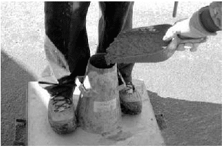
To perform the slump test, the cone, shown in Figures 1 and 2, is dampened and placed on a flat, rigid, nonabsorbent surface. The technician stands on the mold’s foot pieces to hold the mold firmly in place while filling the mold in three layers of equal volume (see Figure 1). The first layer should fill the mold to a depth of about 2 in. (67 mm), the second to 6 in. (156 mm) and the top layer should slightly overfill the mold. Each layer is rodded 25 times with a round steel tamping rod to consolidate the grout before the next layer is placed.

The middle and top layers are rodded through the depth of the layer, penetrating into the layer below. If the grout level falls below the top of the cone while rodding the top layer, grout is added to keep excess grout heaped above the top of the mold at all times. After the top layer is rodded, any excess grout is struck off flush with the top of the cone. Any grout which accumulates around the base of the mold is removed so that it does not interfere with the movement of the slumping grout.

Immediately after striking off and clearing grout from the base of the mold, the mold is lifted in 3 to 7 seconds by raising it vertically using a steady upward lift. The mold should not be twisted or moved sideways during lifting.

The slump is the vertical distance between the top of the cone and the displaced original center of the top surface of the specimen, as shown in Figure 2.

The entire test must be completed within 2 ½ minutes, from start of mold filling to measurement. If there is a decided falling away or shearing off of grout from one side or portion of the grout mass, the test should be disregarded and repeated with a fresh grout sample.

COMPRESSIVE STRENGTH TESTING

When grout compressive strength testing is required, the procedures of ASTM C 1019, Standard Test Method for Sampling and Testing Grout (ref. 3) are used. The Standard contains procedures for both field and laboratory grout compression testing and can be used either to help select grout proportions during preconstruction or as a quality control test for grout preparation uniformity during construction.

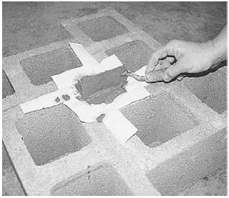
When used as part of a quality assurance program, the number of grout samples to be tested should be specified before the start of construction. One grout sample, as previously described, is used to make three compressive strength specimens. Grout specimens are formed in molds made from concrete masonry units with the same absorption and moisture content characteristics as those being used on the job (see Figures 3, 4).

Because the absorption characteristics of the grout mold must be similar to those experienced by the grout in the wall, when walls are constructed using both concrete and clay masonry units, the grout mold is constructed using both types of units, as shown in Figure 4.

The molds should be located where they can remain undisturbed for 24 to 48 hours, in a level area free from perceptible vibration.

Units for the mold are laid out to form a space with a square cross section, 3 in. (76 mm) or larger on each side, with a height twice its width. Nonabsorbent spacers are placed at the bottom of the square space if needed to achieve the required specimen height. Permeable liners, such as paper towels, are taped to the surrounding masonry units to break the bond between the grout specimen and the masonry units, but still allow water to be absorbed into the units.

Grout is poured into the mold in two lifts of approximately equal depth, with each layer rodded 15 times to eliminate any air bubbles, distributing the strokes uniformly over the cross section of the mold. When rodding the upper layer, the rod should penetrate about ½ in. (13 mm) into the bottom layer. After the upper layer is rodded, the top of the specimen is leveled with a straight edge as shown in Figure 5, such that there are no projections or depressions exceeding in. (3.2 mm). The specimen is then immediately covered with damp fabric or similar material to promote curing.

Within 30 minutes of filling the mold, grout is added to completely fill any depression which may have formed due to initial water absorption. The top of the specimen is leveled again and re-covered to keep it damp until testing.

The specimens should remain undisturbed until the molds are removed, and should be protected from temperature extremes. After 24 to 48 hours, the molds are removed and the specimens are carefully packed for transport, keeping them damp, and shipped to the laboratory for testing.

Within 8 hours of removing the molds, laboratory personnel should store the specimens in a moist room, moist cabinet or water storage tank prior to testing.

Specimen width, height and out-of-plumb are measured and recorded. Average widths are used to calculate the average cross-sectional area, which is used to determine compressive strength based on the maximum compressive load.

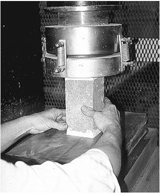
Prior to testing, the specimens should be capped in accordance with the applicable provisions of ASTM C 617, Standard Method of Capping Cylindrical Concrete Specimens, (ref. 6), and tested according to ASTM C 39, Standard Method of Test for Compressive Strength of Molded Concrete Cylinders (ref. 7) (see Figure 6). More detail on the test method and procedures are included in ASTM C 1019.

When approved, other methods of obtaining grout samples, such as drilling cores, may be used to test grout compressive strength. Because test results vary with the method of forming the specimen and with specimen geometry, these test results cannot be directly compared unless previous testing has established a relationship between the two methods of forming and specimen geometries.

Concrete test methods should not be used for grout as they do not simulate water absorption into masonry units. Grout cubes or cylinders formed in nonabsorptive molds will give unreliable results.

SELF-CONSOLIDATING GROUTS

Self-consolidating grout (SCG) is a highly fluid and stable grout mix that is easy to place and does not require consolidation or reconsolidation. SCG is similar in nature to conventional grout, although the mix design is significantly different: proportions of constituent materials are highly controlled and admixtures (typically in the form of superplasticizers with or without viscosity modifiers) are used to produce a plastic grout with desired properties. Controlled aggregate gradation is also important to maintain fluidity without segregation, to produce a mix that results in consistent properties throughout the grout lift.

Because of the fluid nature of the material, traditional measures of consistency and flow such as the slump cone test (ASTM C 143) are not applicable to SCG.

SCG is a relatively new material, which is not yet incorporated into building codes and standards. To date, compliance has been achieved in several cases by using the grout demonstration panel option in Specification for Masonry Structures (ref. 5). Quality assurance provisions are being developed. It is anticipated that SCG testing procedures will be similar to those for self-consolidating concrete, as the two materials are very similar.

REFERENCES

  1. Grout for Concrete Masonry, TEK 09-04A. Concrete Masonry & Hardscapes Association, 2005.
  2. Grouting Concrete Masonry Walls, TEK 03-02A. Concrete Masonry & Hardscapes Association, 2005.
  3. Standard Test Method for Sampling and Testing Grout, ASTM C 1019-03. ASTM International, 2003.
  4. Standard Test Method for Slump of Hydraulic-Cement Concrete, ASTM C 143/143M-03. ASTM International, 2003.
  5. Specification for Masonry Structures, ACI 530.1-05/ASCE 6-05/TMS 602-05. Reported by the Masonry Standards Joint Committee, 2005.
  6. Standard Practice for Capping Cylindrical Concrete Specimens, ASTM C 617-98(2003). ASTM International, 2003.
  7. Standard Test Method for Compressive Strength of Cylindrical Concrete Specimens, ASTM C 39/C 39M-04a. ASTM International, 2004.
  8. Standard Practice for Sampling Freshly Mixed Concrete, ASTM C 172-04. ASTM International, 2004.


Grout for Concrete Masonry

INTRODUCTION

Masonry grout is a cementitious mixture used to fill cores or cavities in masonry construction. While usually added for structural reasons, grout can also increase: fire ratings, security, acoustical performance, termite resistance, blast resistance, thermal storage capacity and anchorage capabilities. Grout is composed of cement, aggregate, lime (optional) and sufficient water to allow ease of placement and ensure complete filling of the grout space. With approval, admixtures may be added to the grout mix. The high initial water content of typical grout mixes compensates for water absorption by the masonry during and after grout placement. The final water-to-cement ratio is significantly reduced, thus grout develops high compressive strength despite its apparent high initial water to cement ratio.

Generally, grout is used to structurally bond wall elements into a wall system. The most common example is in reinforced construction, where grout bonds the steel reinforcing bars to the masonry, allowing them to act as one system in resisting loads. Composite walls consist of two wythes of masonry with a solidly grouted collar joint with or without reinforcing steel. Grouted cores also increase the net cross sectional area of concrete masonry and permit walls to carry higher compressive, shear loads and lateral loads. Masonry cantilever retaining walls are often solidly grouted to increase the wall’s weight, and hence resistance to overturning. Grouted masonry construction is not required to be reinforced, but typically is for design economy. Reinforced masonry construction, however, requires grout to be placed around the reinforcement.

This TEK includes information about: types of grout; grout properties; grout admixtures; and self consolidating grout. Information on grout mixing and placement and on grout testing is contained in Grouting Concrete Masonry Walls, TEK 03-02A and Grout Quality Assurance, TEK 18-08B (refs. 1, 2) respectively.

SPECIFYING GROUT

Grout Type

Grout for use in concrete masonry construction should comply with ASTM C 476, Standard Specification for Grout for Masonry (ref. 3), or the governing building code which may permit grouting options other than those in set forth in ASTM C 476 . ASTM C 476 defines two types of grout: fine and coarse. Fine grout contains sand smaller than 3/8 in. (9.5 mm) as its only aggregate, while coarse grout allows pea gravel smaller than 1/2 in. (13 mm), or other acceptable aggregate, in addition to the sand.

Aggregates for grout must comply with ASTM C 404, Standard Specification for Aggregates for Masonry Grout (ref. 4), which includes requirements for grading, impurities, soundness, and methods of aggregate sampling and testing. When an aggregate does not meet the ASTM C 404 grading requirements, it may still be used provided the requirements of ASTM C 404 section 4.2 are met. These requirements prescribe minimum and maximum aggregate sizes and a minimum grout compressive strength of 2,000 psi (13.79 MPa).

Building codes and ASTM Specifications do not recognize any appreciable compressive strength difference between fine and coarse grouts. The choice of grout type therefore depends primarily on the minimum clear dimensions of the grout space, the grout pour height and construction economics. Coarse grout is typically more economical to produce. See TEK 03-02A (ref. 1) for more information on grout space requirements and grout type selection.

Grout Proportions

ASTM C 476 allows grout mixtures to be determined either by compliance with the proportions listed in Table 1 or by those established through compressive strength testing. Written acceptance of grout mix submittals is required prior to the commencement of grouting operations (ref. 7).

Using the proportions specified in Table 1 is a simple way to demonstrate compliance with ASTM C 476.

When using the specified compressive strength method in ASTM C 476, the grout must be sampled and tested in accordance with ASTM C 1019 (ref. 5) and have a minimum compressive strength of 2,000 psi (13.79 MPa) at 28 days. It must also be mixed to a slump of 8 to 11 in. (203 279 mm) as determined by ASTM C 143/143M (ref. 6). The grout proportions used to produce a grout with acceptable physical properties are then used to produce the grout for the project.

Compressive Strength

While 2,000 psi (13.79 MPa) is the minimum compressive strength required by ASTM C 476, project requirements may require higher strengths. For instance, when the unit strength method is used to determine the specified compressive strength of the masonry, f’m, Specification for Masonry Structures (ref. 7) requires the compressive strength of the grout to equal or exceed f’m but not be less than 2,000 psi (13.79 MPa). As an economic rule of thumb, unless structural criteria dictate otherwise, it is best to balance the specified grout strength with the specified concrete masonry assembly strength so that one element of the system is not considerably stronger than the other, resulting in material overstrength and design conservatism. When using the strength design provisions of the Building Code Requirements for Masonry Structures (ref. 8), a maximum specified grout compressive strength of 5,000 psi (34.47 MPa) for concrete masonry construction is applied. This limitation is based solely on the specified compressive strength of grout and does not limit the actual field-tested grout compressive strength.

Grout Slump

Grout for masonry construction is a high slump material with a flowable consistency to ease placement and facilitate consolidation. Both the Specification for Masonry Structures (ref. 7) and ASTM C476 require grout to have a slump between 8 and 11 in. (203 – 279 mm). Grout must be fluid enough to flow into the smallest grout spaces and around any obstructions, such as reinforcing bars, joint reinforcement, anchors, ties and small mortar protrusions (fins). Lower slump grouts are usually more difficult to place. Although the high slump (high initial water cement ratio of conventional grout) may concern those familiar with lower slump cementitious products such as concrete or mortar, concrete masonry units are absorptive, and the higher water content of grout is critical to insure that in-place grout has sufficient remaining water, after absorption by the masonry units, for cement hydration. Despite grout’s relatively high water to cement ratio, studies have shown that adequate grout compressive strengths and bond strengths are achieved even when using high slump grouts in wet concrete masonry units (ref. 9).

While both codes and standards specify grout slumps in excess of 8 in. (203 mm), there may be certain conditions where lower slumps could be used or may be warranted. For example, if the concrete masonry units are low absorptive units or if the grout spaces are large and the grout lifts are short, lower water content grouts may work fine although care should be taken to assure adequate filling around reinforcement or other obstructions. Likewise, cold weather could present conditions where lower water content grout would be advantageous under certain circumstances (i.e. freezing conditions), but not as a general rule. For demonstrating the suitability of alternate grouting means and/or methods, the grout demonstration panel option detailed in Specification for Masonry Structures (ref. 7) should be used to qualify the proposed method. See CMHA TEK 03-02A (ref. 1) for information on grout demonstration panels.

Production Methods

Production methods for grout are also described in ASTM C 476. These include various forms of site-mixed and ready mixed grout. When cementitious materials and aggregates are stored separately on site and then proportioned into the mixer, they are required to be mixed for at least 5 minutes in a mechanical mixer with sufficient water to bring the grout to the desired consistency. Factory dry blended cementitious materials and aggregate can also be delivered to the job site and must be mixed for the same 5 minute time period. Another option is for the individual dry ingredients to be shipped to the job site in compartments and then mixed with water on site using continuous proportioning equipment and auger mixing to the desired consistency. Grout also may arrive at the job site in a wet-mixed condition. Ready-mixed grout may have the slump adjusted at the site to bring it to the desired consistency. If water is added, the grout must be remixed for at least 1 minute before discharging. When approved by the specifier, grout may be mixed by hand instead of a mechanical mixer when only small volumes are required.

Grout quantities required on a job can vary depending on the specific circumstances of the project. The unit properties, such as absorption and configuration, can have a significant impact.

The delivery method (pumping versus bucketing) can also introduce different amounts of waste. Although the absolute volume of grout waste seen on a large project may be larger than on a comparable small project, smaller projects may experience a larger percentage of grout waste. Table 2 provides guidance for estimating grout quantities.

ADMIXTURES

A variety of admixtures is available to enhance certain grout properties. However, ASTM C 476 requires admixtures to be included in the project documents or to be approved by the purchaser. Likewise, Specification for Masonry Structures (ref. 7) requires admixtures to be accepted by the architect or engineer. Antifreeze compounds, used to lower the freezing point of grout, are prohibited by ASTM C 476. Admixtures containing chlorides should also not be used in grout, because chlorides may corrode steel reinforcement and can contribute to efflorescence in the wall. Several admixtures are available that provide a combination of desirable characteristics, such as shrinkage compensating, plasticizing and retarding. As with any admixture, manufacturer’s directions and dosage rates should be carefully followed. Note that individual admixture results can vary from one cement supplier to another.

Superplasticizers

Superplasticizing admixtures are used to reduce the water content of a plastic cementitious mix while maintaining high flow consistency. They are not normally used in conventional grout (except self consolidating grout) since the excess water is absorbed into the masonry units. In some areas, however, this absorption of excess water has resulted in efflorescence problems. Superplasticizers have been found effective in reducing this problem by reducing the amount of water available for absorption. It should be noted however, that special formulation skills are required to ensure that the grout remains fluid long enough to completely fill all the voids.

Accelerators

In grout, accelerating admixtures increase both the rate of hydration and the amount of heat generated during hydration. They are used in cold weather to decrease grout setting time and increase the rate of strength gain. The increased heat of hydration does not eliminate the need for cold weather protection requirements. Accelerators should be free of chloride materials and not perpetuate the corrosion of embedded metals.

Shrinkage Compensators

Shrinkage compensating admixtures cause a slow, controlled grout expansion that is intended to offset grout shrinkage due to the initial water loss. These admixtures may be especially useful for high-lift grouting, where a large volume of grout is placed and consolidated at one time.

Retarders

Retarding admixtures are used in hot weather to keep the grout workable long enough for placement, consolidation and reconsolidation. They may also be used when the grout cannot be placed right away, as may be the case when the plastic grout will travel a long distance to the job site.

Fly Ash and Blast-Furnace Slag

Fly ash is a by-product of coal combustion, and is not usually thought of as an admixture in the same sense as the chemical admixtures discussed above. Fly ash can be used in grout as a pumping aid or to provide a greater slump with less water. Fly ash can also replace some of the portland cement in the grout mix, which has an economic advantage since the unit cost of fly ash is less than that of portland cement.

Addition rates of fly ash and raw natural pozzolans (ref. 10) or blast furnace slag (ref. 11) are governed by ASTM C 595, Standard Specification for Blended Hydraulic Cements (ref. 12). These products can produce grout mixes with a slower initial strength gain, which may need to be considered in cold weather to achieve the minimum compressive strength previously discussed.

SELF-CONSOLIDATING GROUT

A new grout material is becoming increasingly known in North American masonry markets – self-consolidating grout (SCG). SCG is a highly fluid and stable grout mix that is easy to place and does not require consolidation or reconsolidation. SCG’s mix design is significantly different from conventional grout. SCG is similar in nature to conventional grout, with the exception that the proportions of constituent materials are highly controlled and admixtures (typically in the form of superplasticizers with or without viscosity modifiers) are used to produce a plastic grout with desired properties. Controlled aggregate gradation is also important to maintain fluidity without segregation, to produce a mix that results in consistent properties throughout the grout lift.

Because of the fluid nature of the material, traditional measures of consistency and flow such as the slump cone test (ASTM C 143) are not applicable to SCG. A slump flow test is used instead, which is an adaptation of the conventional slump cone test. In the slump flow test, SCG is loaded into an inverted slump cone. The cone is removed and the flow of the material is observed and measured. Typical slump flow spreads for SCG range from 20 to 30 in. (508-762 mm). Indications of bleeding or segregation should not be seen in the flow spread.

SCG is a relatively new material so it is not yet incorporated into building codes and standards. To date, compliance has been achieved in several cases by using the grout demonstration panel option in Specification for Masonry Structures (ref. 7). Work is under way to standardize and codify this material.

REFERENCES

  1. Grouting Concrete Masonry Walls, TEK 03-02A, Concrete Masonry & Hardscapes Association, 2005.
  2. Grout Quality Assurance, TEK 18-08B, Concrete Masonry & Hardscapes Association, 2005.
  3. Standard Specification for Grout for Masonry, ASTM C 476-02. ASTM International, 2002.
  4. Standard Specification for Aggregates for Masonry Grout, ASTM C 404-04. ASTM International, 2004.
  5. Standard Test Method for Sampling and Testing Grout, ASTM C 1019-03. ASTM International, 2003.
  6. Standard Test Method for Slump of Hydraulic-Cement Concrete, ASTM C 143/143M-03. ASTM International, 2003.
  7. Specification for Masonry Structures, ACI 530.1-05/ASCE 6-05/TMS 602-05. Reported by the Masonry Standards Joint Committee, 2005.
  8. Building Code Requirements for Masonry Structures, ACI 530-05/ASCE 5-05/TMS 402-05. Reported by the Masonry Standards Joint Committee, 2005.
  9. The Effects of Concrete Masonry Unit Moisture Content on Grout Bond and Grout Compressive Strength, MR 11. Concrete Masonry & Hardscapes Association Research and Development Laboratory, 1997.
  10. Standard Specification for Coal Fly Ash and Raw or Calcined Natural Pozzolan for Use in Concrete, ASTM C 618-03. ASTM International, 2003.
  11. Standard Specification for Ground Granulated Blast Furnace Slag for Use in Concrete and Mortars, ASTM C 989-05. ASTM International, 2005.
  12. Standard Specification for Blended Hydraulic Cements, ASTM C 595–03. ASTM International, 2003.