The CMHA Masonry Anchor Bolt Design Calculator is a spreadsheet-based calculator tool to aid in the design of anchor bolts used in masonry construction. The spreadsheet can calculate both bent-bar and headed anchor bolts, either in top-mount or face-mount configuration. Design is based on the 2013 version of TMS 402/ACI 530/ASCE 5. Calculations for both allowable stress as well as strength design are provided.
Lintels function as beams to support the wall weight and other loads over an opening, and to transfer these loads to the adjacent masonry. Because of their rigidity, strength, durability, fire resistance and aesthetics, the most common types of lintels for concrete masonry construction are those manufactured of precast reinforced concrete or reinforced concrete masonry units (ref. 3). The color and surface texture of these lintels can be used as an accent or to duplicate the surrounding masonry.
LINTEL DIMENSIONS
Precast lintel dimensions are illustrated in Figure 1. Precast concrete lintels are manufactured to modular sizes, having specified dimensions corresponding to the concrete masonry units being used in the construction.
A modular lintel length should be specified, with a minimum length of the clear span plus 8 in. (203 mm), to provide at least 4 in. (102 mm) bearing at each end (ref. 1). Additionally, if lintels are subjected to tensile stresses during storage, transportation, handling, or placement, it is recommended that steel reinforcement be provided in both the top and bottom to prevent cracking. Minimum concrete cover over the steel should be 1 ½ in. (13 mm). The lintel width, or width of the combination of side-by-side lintels, should equal the width of the supported masonry wythe.
Lintels should be clearly marked on the top whenever possible to prevent the possibility of improper installation in the wall. In the event the top of the lintel is not marked and may be installed upside down, the same size bars should be used in both the top and bottom.
Figure 1 – Precast Lintel Design Parameters
LINTEL DESIGN
Precast concrete lintels are designed using the strength design provisions of Building Code Requirements for Structural Concrete, ACI 318-99 (ref. 2). In strength design, service loads are increased to account for variations in anticipated loads, becoming factored loads. The lintel is then sized to provide sufficient design strength. Further information on determining design loads for lintels is included in ASD of CM Lintels Based on 2012 IBC/2011 MSJC, TEK 17-01D (ref. 3).
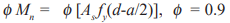
Nominal lintel strength is determined based on the strength design provisions of ACI 318 and then reduced by strength reduction factors, called phi (Φ) factors. These factors account for any variability in materials and construction practices. The resulting capacity needs to equal or exceed the factored loads. Precast concrete strength reduction factors are 0.9 and 0.85 for flexure and shear, respectively (ref. 2).
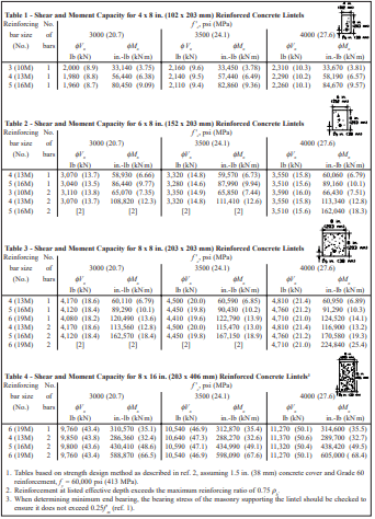
Tables 1 through 4 list design moment and shear strengths for various precast lintel sizes and concrete strengths, based on the following criteria (ref. 2).
Flexural strength:
Shear strength, no shear reinforcement:
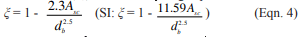
ACI 318 contains requirements for minimum and maximum reinforcing steel areas to ensure a minimum level of performance. Minimum reinforcement area for lintels is As min = 3(f’c)½bd/fy but not less than 200bd/fy. In addition, the reinforcement ratio is limited to 75% of the balanced reinforcement ratio, ρmax = 0.75ρb.
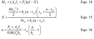
Deflection criteria for lintels is based on controlling cracking in the masonry being supported. Consequently, less deflection is allowed when the lintel supports unreinforced masonry. In this case, lintel deflection is limited to the effective span of the lintel (measured in inches) divided by 600 (L/600) (ref. 1). In addition, ACI 318 limits precast lintel deflection to L/240 when the element supported by the lintel is not likely to be damaged by large deflections, and L/480 when the element supported by the lintel is likely to be damaged by large deflections. Lintel deflection is calculated based on the effective moment of inertia, Ie, as follows (ref. 2, Section 9.5.2.3).
Shrinkage and creep due to sustained loads cause additional long-term deflections over and above those occurring when loads are first applied. ACI 318 requires that deflections due to shrinkage and creep are included, and provides an expression to estimate this additional deflection (ACI 318 Section 9.5.2.5):
λ = ξ/(1+50ρ’)
where ξ = 2.0 for exposures of 5 years or more.
Figure 2 – Strength Design Structural Model
DESIGN EXAMPLE
The residential basement wall shown in Figure 3 needs a lintel over the window opening. The floor live load is 400 lb (1.8 kN) per joist and the floor dead load is 100 lb (0.44 kN) per joist. Consider the floor joist loads, spaced at 16 in. (406 mm) on center, as uniformly distributed. Use a lintel self-weight of 61 lb/ ft (0.89 kN/m) and weight of 77.9 lb/ft2 (3.73 kPa) for the bond beam at the top of the wall over the lintel.
Determine effective depth, d: Assuming an 8 in. (203 mm) high lintel with two No. 4 (13M) bars, d = 7.625 in. – 1.5 in. – 0.5/2 in. = 5.88 in. (149 mm)
Check for arching action: The effective span length, L = 96 + 5.88 = 101.9 in. (2588 mm). Since the height of masonry above the opening is less than L/2, arching of the masonry over the opening cannot be assumed (see ref. 4 for detailed information about determining arching action).
For deflection calculations use loads as given above. For strength design multiply live loads by 1.7 and dead loads by 1.4. Maximum moment and shear for strength design:
Total deflection, ∆tot = ∆max + ∆LT = 0.114 + 0.228 = 0.342 in. (8.7 mm)
Deflection limit for this case is L/240 = 101.9 in./240 = 0.42 in. (10.7 mm) > 0.342 in. (8.7 mm) OK
Figure 3 – Wall Configuration for Design Example
Table 1 to Table 4
NOTATIONS
a = depth of equivalent rectangular stress block, in. (mm) As = area of tension reinforcement, in.² (mm²) b = actual width of lintel, in. (mm) c = distance from extreme compression fiber to neutral axis, in. (mm) C = resultant compressive force in concrete, lb (kN) d = distance from extreme compression fiber to centroid of tension reinforcement, in. (mm) Db beam = dead load of bond beam, lb/ft (kN/m) Dfloor = dead load of floor, lb/ft (kN/m) Dlintel = dead load of lintel, lb/ft (kN/m) Dtot = total design dead load, lb/ft (kN/m) Ec = modulus of elasticity of concrete, psi (MPa) f ‘c = specified compressive strength of concrete, psi (MPa) fr = modulus of rupture of concrete, psi (MPa) fy = specified yield strength of reinforcement, psi (MPa) (60,000 psi, 413 MPa) Icr = moment of inertia of cracked section transformed to concrete, in.4 (cm4) Ie = effective moment of inertia, in.4 (cm4) Ig = moment of inertia of gross concrete section about centroidal axis, in.4 (cm4) L = effective length, clear span plus depth of member, not to exceed the distance between center of supports, in. (mm) LL = live load, lb/ft (kN/m) Mcr = cracking moment, in.-lb (kN⋅m) Mmax = maximum factored moment on section, in.-lb (kN⋅m) Mmax uf = maximum unfactored moment on section, in.-lb (kN⋅m) Mn = nominal moment strength, in.-lb/ft (kN⋅m/m) n = modular ratio, Es/Ec T = resultant tensile force in steel reinforcement, lb (kN) Vmax = maximum factored shear on section, lb (kN) Vn = nominal shear strength, lb (kN) w = uniform load, lb/in. (kN/m) wc = density of concrete, pcf (kN/m³) yt = distance from centroidal axis of gross section to extreme fiber in tension, in. (mm) ∆max = maximum immediate deflection, in. (mm) ∆LT = long-term deflection, in. (mm) ∆tot = total deflection, in. (mm) εc = strain in concrete, in./in. (mm/mm) εs = strain in steel reinforcement, in./in. (mm/mm) ξ = time-dependent factor for sustained load λ = multiplier for additional long-term deflection Φ = strength reduction factor ρ = reinforcement ratio, As/bd ρ’ = reinforcement ratio for nonprestressed compression reinforcement, As‘/bd ρb = reinforcement ratio producing balanced strain conditions ρmax = limit on reinforcement ratio
REFERENCES
Building Code Requirements for Masonry Structures, ACI 530-99/ASCE 5-99/TMS 402-99. Reported by the Masonry Standards Joint Committee, 1999.
Building Code Requirements for Structural Concrete, ACI 318-99. American Concrete Institute, 1999.
ASD of CM Lintels Based on 2012 IBC/2011 MSJC, TEK 17-01D, Concrete Masonry & Hardscapes Association, 2011.
Using concrete masonry in retaining walls, abutments and other structural components designed primarily to resist lateral pressure permits the designer and builder to capitalize on masonry’s unique combination of structural and aesthetic features—excellent compressive strength; proven durability; and a wide selection of colors, textures and patterns. The addition of reinforcement to concrete masonry greatly increases the tensile strength and ductility of a wall, providing higher load resistance.
In cantilever retaining walls, the concrete base or footing holds the vertical masonry wall in position and resists overturning and sliding caused by lateral soil loading. The reinforcement is placed vertically in the cores of the masonry units to resist the tensile stresses developed by the lateral earth pressure.
DESIGN
Retaining walls should be designed to safely resist overturning and sliding due to the forces imposed by the retained backfill. The factors of safety against overturning and sliding should be no less than 1.5 (ref. 7). In addition, the bearing pressure under the footing or bottom of the retaining wall should not exceed the allowable soil bearing pressure.
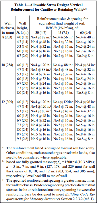
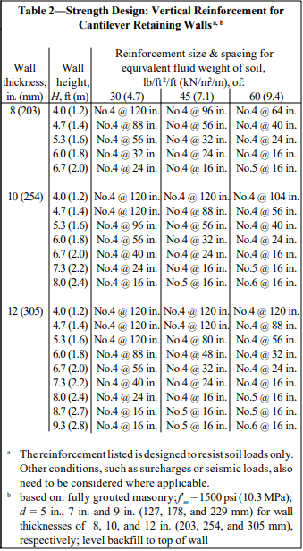
Recommended stem designs for reinforced cantilever retaining walls with no surcharge are contained in Tables 1 and 2 for allowable stress design and strength design, respectively. These design methods are discussed in detail in ASD of Concrete Masonry (2012 IBC & 2011 MSJC), TEK 14-07C, and Strength Design Provisions for Concrete Masonry, TEK 14-04B (refs. 5, 6).
Figure 2—Reinforced Cantilever Retaining Wall Design Example
DESIGN EXAMPLE
The following design example briefly illustrates some of the basic steps used in the allowable stress design of a reinforced concrete masonry cantilever retaining wall.
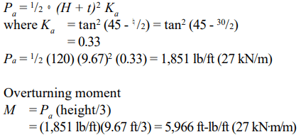
Example: Design the reinforced concrete masonry cantilever retaining wall shown in Figure 2. Assume level backfill, no surcharge or seismic loading, active earth pressure and masonry laid in running bond. The coefficient of friction between the footing and foundation soil, k1, is 0.25, and the allowable soil bearing pressure is 2,000 psf (95.8 kPa) (ref. 7).
F.S. (overturning) = total resisting moment about toe/overturning moment = 14,670/5,966 = 2.4 > 1.5 O.K.
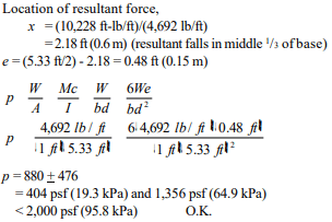
e. Pressure on footing
f. Determine size of key
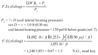
Passive lateral soil resistance = 150 psf/ft of depth and may be increased 150 psf for each additional foot of depth to a maximum of 15 times the designated value (ref. 7). The average soil pressure under the footing is: ½ (1,356 + 404) = 880 psf (42.1 kPa).
Equivalent soil depth: 880 psf/120 pcf = 7.33 ft (2.23 m)
Pp = (150 psf/ft)(7.33 ft) = 1,100 psf (52.7 kPa)
For F.S. (sliding) = 1.5, the required total passive soil resistance is: 1.5(1,851 lb/ft) = 2,776 lb/ft (41 kN/m)
The shear key must provide for this value minus the frictional resistance: 2,776 – 1,248 = 1,528 lb/ft (22 kN/m).
Depth of shear key = (1,528 lb/ft)/(1,100 psf) = 1.39 ft (0.42 m), try 1.33 ft (0.41 m).
At 1.33 ft, lateral resistance = (1,100 psf) + (150 psf/ft)(1.33 ft) = 1,300 lb/ft (19 kN/m) Depth = (1,528 lb/ft)/[½ (1,100 + 1,300)] = 1.27 ft (0.39 m) < 1.33 ft (0.41 m) O.K.
g. Design of masonry
Tables 1 and 2 can be used to estimate the required reinforcing steel based on the equivalent fluid weight of soil, wall thickness, and wall height. For this example, the equivalent fluid weight = (Ka)(º) = 0.33 x 120 = 40 pcf (6.2 kN/m³).
Using allowable stress design (Table 1) and the conservative equivalent fluid weight of soil of 45 pcf (7.1 kN/m³), this wall requires No. 6 bars at 16 in. o.c. (M #19 at 406 mm o.c.). Using strength design (Table 2), this wall requires No. 5 bars at 16 in. o.c. (M #16 at 406 mm o.c.).
h. Design of footing
The design of the reinforced concrete footing and key should conform to American Concrete Institute requirements. For guidance, see ACI Standard 318 (ref. 2) or reinforced concrete design handbooks.
Table 1—Allowable Stress Design: Vertical Reinforcement for Cantilever Retaining Walls
Table 2—Strength Design: Vertical Reinforcement for Cantilever Retaining Walls
CONSTRUCTION
Materials and construction practices should comply with applicable requirements of Specification for Masonry Structures (ref. 4), or applicable local codes.
Footings should be placed on firm undisturbed soil, or on adequately compacted fill material. In areas exposed to freezing temperatures, the base of the footing should be placed below the frost line. Backfilling against retaining walls should not be permitted until the masonry has achieved sufficient strength or the wall has been adequately braced. During backfilling, heavy equipment should not approach closer to the top of the wall than a distance equal to the height of the wall. Ideally, backfill should be placed in 12 to 24 in. (305 to 610 mm) lifts, with each lift being compacted by a hand tamper. During construction, the soil and drainage layer, if provided, also needs to be protected from saturation and erosion.
Provisions must be made to prevent the accumulation of water behind the face of the wall and to reduce the possible effects of frost action. Where heavy prolonged rains are anticipated, a continuous longitudinal drain along the back of the wall may be used in addition to through-wall drains.
Climate, soil conditions, exposure and type of construction determine the need for waterproofing the back face of retaining walls. Waterproofing should be considered: in areas subject to severe frost action; in areas of heavy rainfall; and when the backfill material is relatively impermeable. The use of integral and post-applied water repellents is also recommended. The top of masonry retaining walls should be capped or otherwise protected to prevent water entry.
REFERENCES
Building Code Requirements for Masonry Structures, ACI 530-05/ASCE 5-05/TMS 402-05. Reported by the Masonry Standards Joint Committee, 2005.
Building Code Requirements for Structural Concrete and Commentary, ACI 318-02. Detroit, MI: American Concrete Institute, 2002.
Das, B. M. Principles of Foundation Engineering. Boston, MA: PWS Publishers, 1984.
Specification for Masonry Structures, ACI 530.1-05/ASCE 6-05/TMS 602-05. Reported by the Masonry Standards Joint Committee, 2005.
ASD of Concrete Masonry (2012 IBC & 2011 MSJC), TEK 14-07C, Concrete Masonry & Hardscapes Association, 2004.
Strength Design Provisions for Concrete Masonry, TEK 14-04B, Concrete Masonry & Hardscapes Association, 2008.
2003 International Building Code. International Code Council, 2003.
NOTATIONS
a length of footing toe, in. (mm) B width of footing, ft (m) d distance from extreme compression fiber to centroid of tension reinforcement, in. (mm) e eccentricity, in. (mm) F.S. factor of safety f’m specified compressive strength of masonry, psi (MPa) H total height of backfill, ft (m) I moment of inertia, ft4 (m4) Ka active earth pressure coefficient k1 coefficient of friction between footing and foundation soil M maximum moment in section under consideration, ft-lb/ft (kN⋅m/m) Pa resultant lateral load due to soil, lb/ft (kN/m) Pp passive earth pressure, lb/ft (N/m) p pressure on footing, psf (MPa) T thickness of wall, in. (mm) t thickness of footing, in. (mm) W vertical load, lb/ft (N/m) x location of resultant force, ft (m) º density of soil, pcf (kg/m³) ¤ angle of internal friction of soil, degreesDisclaimer: Although care has been taken to ensure the enclosed information is as accurate and complete as possible, NCMA does not assume responsibility for errors or omissions resulting from the use of this TEK.
Although concrete masonry foundation walls can be constructed without reinforcing steel, reinforcement may be required for walls supporting large soil backfill loads. The strength design provisions found in Chapter 3 of Building Code Requirements for Masonry Structures (ref. 1) typically provides increased economy over the allowable stress design method, as thinner walls or larger reinforcing bar spacings often result from a strength design analysis. Strength design criteria are presented in detail in TEK 14-04B, Strength Design Provisions for Concrete Masonry (ref. 2).
DESIGN LOADS
Soil imparts lateral loads on foundation walls. The load is assumed to increase linearly with depth, resulting in a triangular load distribution on the wall. This lateral soil load is expressed as an equivalent fluid pressure, with units of pounds per square foot per foot of depth (kN/m²/m). For strength design analysis, this lateral soil pressure is increased by multiplying by a load factor, which provides a factor of safety against overload conditions. The maximum moment on the wall depends on the total wall height, the soil backfill height, the wall support conditions, the factored soil load, the existence of any surcharges on the soil and the presence of saturated soils.
Foundation walls also provide support for the structure above the foundation, transferring vertical loads to the footing. Vertical compression counteracts flexural tension, increasing the wall’s resistance to flexure. In low-rise construction, these vertical loads are typically small in relation to the compressive strength of the concrete masonry. Vertical load effects are not addressed in this TEK.
DESIGN TABLES
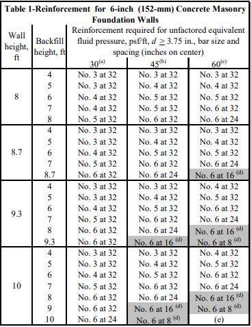
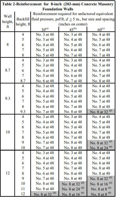
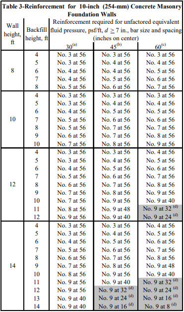
Tables 1 through 4 present reinforcement schedules for 6, 8, 10 and 12-in. (152, 203, 254 and 305-mm) walls, respectively. Additional reinforcement alternatives may be appropriate, and can be verified with an engineering analysis. Walls from 8 to 16 ft (2.4 to 4.9 m) high and soil pressures of 30, 45 and 60 psf/ft (4.7, 7.0, and 9.4 kN/m²/m) are included.
The effective reinforcement depth, d, assumed for the analyses are practical values, taking into account variations in face shell thickness, a range of reinforcing bar sizes, minimum required grout cover and construction tolerances for placing the reinforcement.
The following assumptions also apply to the values in Tables 1 through 4:
there are no surcharges on the soil adjacent to the wall,
there are negligible axial loads on the wall,
the wall is simply supported at top and bottom,
the wall is grouted at cells containing reinforcement (although solid grouting is acceptable),
section properties are based on minimum face shell and web thickness requirements of ASTM C 90 (ref. 3),
the specified compressive strength of masonry, f’m, is 1500 psi (10.3 MPa),
Grade 60 (413 MPa) reinforcement,
reinforcement requirements listed account for a soil load factor of 1.6 (ref. 6),
the maximum width of the compression zone is limited to six times the wall thickness, or a 72 in. (1,829 mm) vertical bar spacing, whichever is smaller,
reinforcing steel is placed toward the tension (interior) face of the wall (as shown in Figure 1), and
the soil is well drained to preclude the presence of saturated soil.
Table 1-Reinforcement for 6-inch (152-mm) Concrete Masonry Foundation Walls
Table 2-Reinforcement for 8-inch (203-mm) Concrete Masonry Foundation Walls
Table 3-Reinforcement for 10-inch (254-mm) Concrete Masonry Foundation Walls
Table 4-Reinforcement for 12-inch (305-mm) Concrete Masonry Foundation Walls
DESIGN EXAMPLE
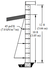
Wall: 12-in. (305 mm) thick concrete masonry foundation wall, 12 ft (3.66 m) high
Soil: equivalent fluid pressure is 45 psf/ft (7.0 kN/m²/m) (excluding soil load factors), 10 ft (3.05 m) backfill height
Using Table 4, the wall can be adequately reinforced using No. 9 bars at 72 in. o.c. (M# 29 at 1,829 mm).
Design Example
CONSTRUCTION ISSUES
This section discusses those issues which directly relate to structural design assumptions. See TEK 03-11, Concrete Masonry Basement Wall Construction and TEK 05-03A, Concrete Masonry Foundation Wall Details (refs. 4, 5) for more complete information on building concrete masonry foundation walls.
Figure 1 illustrates wall support conditions, drainage and protection from water. Before backfilling, the floor diaphragm must be in place, or the wall must be properly braced to resist the soil load. Ideally, the backfill should be free-draining granular material, free from expansive soils or other deleterious materials.
The assumption that there are no surcharges on the soil means that heavy equipment should not be operated directly adjacent to any basement wall system. In addition, the backfill materials should be placed and compacted in several lifts. Care should be taken when placing backfill materials to prevent damaging the drainage, waterproofing or exterior insulation systems.
Figure 1—Typical Reinforced Basement Wall
REFERENCES
Building Code Requirements for Masonry Structures, ACI 530-02/ASCE 5-02/TMS 402-02. Reported by the Masonry Standards Joint Committee, 2002.
Strength Design Provisions for Concrete Masonry, TEK 14-04B, Concrete Masonry & Hardscapes Association, 2008.
Standard Specification for Loadbearing Concrete Masonry Units, ASTM C 90-03. ASTM International, 2003.
The 1999 Building Code Requirements for Masonry Structures, ACI 530/ASCE 5/TMS 402 (ref. 1), was the first masonry code in the United States to include general design provisions for prestressed masonry. Prestressing masonry is a process whereby internal compressive stresses are introduced to counteract tensile stresses resulting from applied loads. Compressive stresses are developed within the masonry by tensioning a steel tendon, which is anchored to the top and bottom of the masonry element (see Figure 1). Post-tensioning is the primary method of prestressing, where the tendons are stressed after the masonry has been placed. This TEK focuses on the design of concrete masonry walls constructed with vertical post-tensioned tendons.
Advantages
Prestressing has the potential to increase the flexural strength, shear strength and stiffness of a masonry element. In addition to increasing the strength of an element, prestressing forces can also close or minimize the formation of some cracks. Further, while research (refs. 14, 15) indicates that ductility and energy dissipation capacity are enhanced with prestressing, Building Code Requirements for Masonry Structures (ref. 1) conservatively does not take such performance into account.
Post-tensioned masonry can be an economical alternative to conventionally reinforced masonry. One major advantage of prestressing is that it allows a wall to be reinforced without the need for grout. Also, the number of prestressing tendons may be less than the number of reinforcing bars required for the same flexural strength.
Post-tensioning masonry is primarily applicable to walls, although it can also be used for beams, piers, and columns. Vertical post-tensioning is most effective for increasing the structural capacity of elements subjected to relatively low axial loads. Structural applications include loadbearing, nonloadbearing and shear walls of tall warehouses and gymnasiums, and commercial buildings, as well as retaining walls and sound barrier walls. Post-tensioning is also an option for strengthening existing walls.
Figure 1—Schematic of Typical Post-Tensioned Wall
MATERIALS
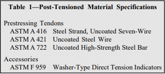
Post-tensioned wall construction uses standard materials: units, mortar, grout, and perhaps steel reinforcement. In addition, post-tensioning requires tendons, which are steel wires, bars or strands with a higher tensile strength than conventional reinforcement. Manufacturers of prestressing tendons must supply stress relaxation characteristics for their material if it is to be used as a prestressing tendon. Specifications for those materials used specifically for post-tensioning are given in Table 1. Other material specifications are covered in references 9 through 12. Construction is covered in Post-Tensioned Concrete Masonry Wall Construction, TEK 03-14 (ref. 3).
Table 1—Post-Tensioned Material Specifications
CORROSION PROTECTION
As with conventionally reinforced masonry structures, Building Code Requirements for Masonry Structures (ref. 1) mandates that prestressing tendons for post-tensioned masonry structures be protected against corrosion. As a minimum, the prestressing tendons, anchors, couplers and end fittings in exterior walls exposed to earth or weather must be protected. All other walls exposed to a mean relative humidity exceeding 75% must also employ some method of corrosion abatement. Unbonded tendons can be protected with galvanizing, epoxy coating, sheathing or other alternative method that provides an equivalent level of protection. Bonded tendons are protected from corrosion by the corrugated duct and prestressing grout in which they are encased.
DESIGN LOADS
As for other masonry structures, minimum required design loads are included in Minimum Design Loads for Buildings and Other Structures, ASCE 7 (ref. 5), or the governing building codes. If prestressing forces are intended to resist lateral loads from earthquake, a factor of 0.9 should be applied to the strength level prestress forces (0.6 for allowable stress design) as is done with gravity loads.
STRUCTURAL DESIGN
The design of post-tensioned masonry is based on allowable stress design procedures, except for laterally restrained tendons which use a strength design philosophy. Building Code Requirements for Masonry Structures (ref. 1) prescribes allowable stresses for unreinforced masonry in compression, tension and shear, which must be checked against the stresses resulting from applied loads.
The flexural strength of post-tensioned walls is governed by either the flexural tensile stress of the masonry (the flexural stress minus the post-tensioning and dead load stress), the masonry compressive stress, the tensile stress within the tendon, the shear capacity of the masonry or the buckling capacity of the wall.
Masonry stresses must be checked at the time of peak loading (independently accounting for both short-term and long-term losses), at the transfer of post-tensioning forces, and during the jacking operation when bearing stresses may be exceeded. Immediately after transfer of the post-tensioning forces, the stresses in the steel are the largest because long-term losses have not occurred. Further, because the masonry has had little time to cure, the stresses in the masonry will be closer to their capacity. Once long-term losses have transpired, the stresses in both the masonry and the steel are reduced. The result is a coincidental reduction in the effective capacity due to the prestressing force and an increase in the stresses the fully cured masonry can resist from external loads.
Effective Prestress
Over time, the level of prestressing force decreases due to creep and shrinkage of the masonry, relaxation of the prestressing tendons and potential decreases in the ambient temperature. These prestressing losses are in addition to seating and elastic shortening losses witnessed during the prestressing operation. In addition, the prestressing force of bonded tendons will decrease along the length of the tendon due to frictional losses. Since the effective prestressing force varies over time, the controlling stresses should be checked at several stages and loading conditions over the life of the structure.
The total prestress loss in concrete masonry can be assumed to be approximately 35%. At the time of transfer of the prestressing force, typical losses include: 1% seating loss + 1% elastic shortening = 2%. Additional losses at service loads and moment strength include:
relaxation
3%
temperature
10%
creep
8%
CMU shrinkage
7%
contingency
5%
total
33%
Prestress losses need to be estimated accurately for a safe and economical structural design. Underestimating losses will result in having less available strength than assumed. Overestimating losses may result in overstressing the wall in compression.
Effective Width
In theory, a post-tensioning force functions similarly to a concentrated load applied to the top of a wall. Concentrated loads are distributed over an effective width as discussed in the commentary on Building Code Requirements for Masonry Structures (ref. 1). A general rule-of-thumb is to use six times the wall thickness as the effective width.
Elastic shortening during post-tensioning can reduce the stress in adjacent tendons that have already been stressed. Spacing the tendons further apart than the effective width theoretically does not reduce the compressive stress in the effective width due to the post-tensioning of subsequent tendons. The applied loads must also be consolidated into the effective width so the masonry stresses can be determined. These stresses must be checked in the design stage to avoid overstressing the masonry.
Flexure
Tensile and compressive stresses resulting from bending moments applied to a section are determined in accordance with conventional elastic beam theory. This results in a triangular stress distribution for the masonry in both tension and compression. Maximum bending stress at the extreme fibers are determined by dividing the applied moment by the section modulus based on the minimum net section.
Net Flexural Tensile Stress
Sufficient post-tensioning force needs to be provided so the net flexural tensile stress is less than the allowable values. Flexural cracking should not occur if post-tensioning forces are kept within acceptable bounds. Flexural cracking due to sustained post-tensioning forces is believed to be more severe than cracking due to transient loading. Flexural cracks due to eccentric post-tensioning forces will remain open throughout the life of the wall, and may create problems related to water penetration, freeze-thaw or corrosion. For this reason, Building Code Requirements for Masonry Structures (ref. 1) requires that the net flexural tensile stress be limited to zero at transfer of the post-tensioning force and for service loadings with gravity loads only.
Axial Compression
Compressive stresses are determined by dividing the sum of the post-tensioning and gravity forces by the net area of the section. They must be less than the code prescribed (ref. 1) allowable values of axial compressive stress.
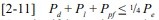
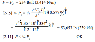
Walls must also be checked for buckling due to gravity loads and post-tensioning forces from unrestrained tendons. Laterally restrained tendons can not cause buckling; therefore only gravity compressive forces need to be checked for buckling in walls using laterally restrained tendons. Restraining the tendons also ensures that the tendons do not move laterally in the wall when the masonry deflects. The maximum compressive force that can be applied to the wall based upon ¼ buckling is Pe, per equation 2-11 of Building Code Requirements for Masonry Structures (ref. 1).
Combined Axial and Flexural Compressive Stress
Axial compressive stresses due to post-tensioning and gravity forces combine with flexural compressive stresses at the extreme fiber to result in maximum compressive stress. Conversely, the axial compressive stresses combine with the flexural tensile stresses to reduce the absolute extreme fiber stresses. To ensure the combination of these stresses does not exceed code prescribed allowable stresses, a unity equation is checked to verify compliance. Employing this unity equation, the sum of the ratios of applied-to-allowable axial and flexural stresses must be less than one. Unless standards (ref. 5) limit its use, an additional one-third increase in allowable stresses is permitted for wind and earthquake loadings, as is customary with unreinforced and reinforced masonry. Further, for the stress condition immediately after transfer of the post-tensioning force, a 20% increase in allowable axial and bending stresses is permitted by Building Code Requirements for Masonry Structures (ref. 1).
Shear
As with all stresses, shear stresses are resisted by the net area of masonry, and the wall is sized such that the maximum shear stress is less than the allowable stress. In addition, the compressive stress due to post-tensioning can be relied on to increase allowable shear stresses in some circumstances.
Post-Tensioning Tendons
The stress in the tendons is limited (ref. 1) such that:
the stress due to the jacking force does not exceed 0.94fpy, 0.80fpu, nor that recommended by the manufacturer of the tendons or anchorages,
the stress immediately after transfer does not exceed 0.82fpy nor 0.74fpu, and
the stress in the tendons at anchorages and couplers does not exceed 0.78fpy nor 0.70fpu.
DETERMINATION OF POST-TENSIONING FORCES
Case (a) after prestress losses and at peak loading:
Assuming that the moment, M, due to wind or earthquake loadings is large relative to the eccentric load moment, the critical location will be at the mid-height of the wall for simply-supported walls, and the following equations apply (bracketed numbers are the applicable Building Code Requirements for Masonry Structures (ref. 1) equation or section numbers):
The 1.33 factor in Equation [2-10] represents the one- third increase in allowable stress permitted for wind and earthquake loadings. If the moment, M, is a result of soil pressures (as is the case for retaining walls), the 1.33 factor in Equation [2-10] must be replaced by 1.00.
Note that if the tendons are laterally restrained, Ppf should not be included in Equation [2-11].
(under the load combination of prestressing force and dead load only)
Additional strength design requirements for laterally restrained tendons:
Equation 4-3 above applies to members with uniform width, concentric reinforcement and prestressing tendons and concentric axial load. The nominal moment strength for other conditions should be determined based on static moment equilibrium equations.
Case (b) at transfer of post-tensioning:
Assuming that vertical live loads are not present during post-tensioning, the following equations apply. The worst case is at the top of the wall where post-tensioning forces are applied.
For cantilevered walls, these equations must be modified to the base of the wall.
If the eccentricity of the live load, Pl, is small, neglecting the live load in Equation [2-10] may also govern.
Case (c) bearing stresses at jacking:
Bearing stresses at the prestressing anchorage should be checked at the time of jacking. The maximum allowable bearing stress at jacking is 0.50f’mi per Building Code Requirements for Masonry Structures (ref. 1) section 4.9.4.2.
DESIGN EXAMPLE
Design a simply-supported exterior wall 12 ft (3.7 m) high for a wind load of 15 psf (0.72 kPa). The wall is constructed of concrete masonry units complying with ASTM C 90 (ref. 6). The units are laid in a full bed of Type S Portland cement lime mortar complying with ASTM C 270 (ref. 7). The specified compressive strength of the masonry (f’m) is 1,500 psi (10.3 MPa). The wall will be post-tensioned with 7/16 in. (11 mm) diameter laterally restrained tendons when the wall achieves a compressive strength of 1,250 psi (8.6 MPa). Axial load and prestress are concentric.
Given: 8 in. (203 mm) CMU tf = 1.25 in. (32 mm) f’m = 1,500 psi (10.3 MPa) f’mi = 1,250 psi (8.6 MPa) Fbt = 25 psi (0.17 MPa) (Type S Portland cement/lime mortar) fpy = 100 ksi (690 MPa) (bars) fpu = 122 ksi (840 MPa) Aps = 0.14 in² (92 mm²) Es = 29 x 106 psi (200 GPa) Em = 900 f’m = 1.35 x 10⁶ psi (9,300 MPa) n = Es/Em = 21.5 d = 7.625/2 in. = 3.81 in. (97 mm) (tendons placed in the center of the wall) unit weight of CMU wall = 39 psf (190 kg/m²) (ref. 13)
Maximum tendon stresses: Determine governing stresses based on code limits (ref. 1):
At jacking:
0.94 fpy = 94.0 ksi (648 MPa)
0.80 fpu = 97.6 ksi (673 MPa)
At transfer:
0.82 fpy = 82.0 ksi (565 MPa)
0.74 fpu = 90.3 ksi (623 MPa)
At service loads:
0.78 fpy = 78.0 ksi (538 MPa) ⇒ governs
0.70 fpu = 85.4 ksi (589 MPa)
Because the tendon’s specified tensile strength is less than 150 ksi (1,034 MPa), fps = fse (per ref. 1 section 4.5.3.3.4).
Prestress losses: Assume 35% total loss (as described in the Effective Prestress section above).
Tendon forces: Determine the maximum tendon force, based on the governing tendon stress determined above for each case of jacking, transfer and service. At transfer, include 2% prestress losses. At service, include the full 35% losses. Tendon capacity at jacking = 0.94 fpyAps = 13.3 kips (59 kN) Tendon capacity at transfer = 0.82 fpyAps A x 0.98 = 11.4 kips (51 kN) (including transfer losses) Tendon capacity at service = 0.78 fpyAps A x 0.65 = 7.2 kips (32 kN) (including total losses)
Try tendons at 48 in. (1,219 mm) on center (note that this tendon spacing also corresponds to the maximum effective prestressing width of six times the wall thickness).
Determine prestressing force, based on tendon capacity determined above: at transfer: Ppi = 11.4 kips/4 ft = 2,850 lb/ft (41.6 kN/m) at service: Ppf = 7.2 kips/4 ft = 1,800 lb/ft (26.3 kN/m)
Wall section properties: (ref. 8) 8 in. (203 mm) CMU with full mortar bedding: An = 41.5 in.²/ft (87,900 mm²/m) I = 334 in.4/ft (456 x 106 mm4/m) S = 87.6 in.³/ft (4.71 x 106 mm³/m) r = 2.84 in. (72.1 mm)
At service loads: At service, the following are checked: combined axial compression and flexure using the unity equation (equation 2-10); net tension in the wall; stability by ensuring the compressive load does not exceed one-fourth of the buckling load, Pe, and shear and moment strength.
Check combined axial compression and flexure:
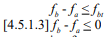
Check tension for load combination of prestress force and dead load only (per ref. 1 section 4.5.1.3):
Check stability: Because the tendons are laterally restrained, the prestressing force, Ppf, is not considered in the determination of axial load ( per ref. 1 section 4.5.3.2), and the wall is not subject to live load in this case, so equation 2-11 reduces to:
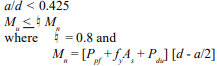
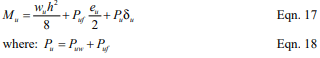
Check moment strength: Building Code Requirements for Masonry Structures section 4.5.3.3 includes the following criteria for moment strength of walls with laterally restrained tendons:
In addition, the compression zone must fall within the masonry, so a < tf.
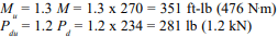
where 1.3 and 1.2 are load factors for wind and dead loads, respectively.
At transfer: Check combined axial compression and flexure using the unity equation (equation 2-10) and net tension in the wall.
Check tension for load combination of prestress force and dead load only (per ref. 1 section 4.5.1.3):
Therefore, use 7/16 in. (11 mm) diameter tendons at 48 in. (1,219 mm) o.c. Note that although wall design is seldom governed by out-of-plane shear, the shear capacity should also be checked.
NOTATIONS
An net cross-sectional area of masonry section, in.² (mm²) Aps threaded area of post-tensioning tendon, in.² (mm²) As cross-sectional area of mild reinforcement, in.² (mm²) a depth of an equivalent compression zone at nominal strength, in. (mm) b width of section, in. (mm) d distance from extreme compression fiber to centroid of prestressing tendon, in. (mm) Es modulus of elasticity of prestressing steel, psi (MPa) Em modulus of elasticity of masonry, psi (MPa) ed eccentricity of dead load, in. (mm) el eccentricity of live load, in. (mm) ep eccentricity of post-tensioning load, in. (mm) Fa allowable masonry axial compressive stress, psi (MPa) Fai allowable masonry axial compressive stress at transfer, psi (MPa) Fb allowable masonry flexural compressive stress, psi (MPa) Fbi allowable masonry flexural compressive stress at transfer, psi (MPa) Fbt allowable flexural tensile strength of masonry, psi (MPa) fa axial stress after prestress loss, psi (MPa) fai axial stress at transfer, psi (MPa) fb flexural stress after prestress loss, psi (MPa) fbi flexural stress at transfer, psi (MPa) f’m specified compressive strength of masonry, psi (MPa) f’mi specified compressive strength of masonry at time of transfer of prestress, psi (MPa) fps stress in prestressing tendon at nominal strength, psi (MPa) fpu specified tensile strength of prestressing tendon, ksi (MPa) fpy specified yield strength of prestressing tendon, ksi (MPa) fse effective stress in prestressing tendon after all pre-stress losses have occurred, psi (MPa) fy specified yield strength of steel for reinforcement and anchors, psi (MPa) h masonry wall height, in. (mm) I moment of inertia of net wall section of extreme fiber tension or compression, in.4/ft (mm4/m) M moment due to lateral loads, ft-lb (N⋅m) Mn nominal moment strength, ft-lb (N⋅m) Mu factored moment due to lateral loads, ft-lb (N⋅m) n modular ratio of prestressing steel and masonry (Es/Em) Pd axial dead load, lb/ft (kN/m) Pdu factored axial dead load, lb/ft (kN/m) Pe Euler buckling load, lb/ft (kN/m) Pl axial live load, lb/ft (kN/m) Plu factored axial live load, lb/ft (kN/m) Ppi prestress force at transfer, lb/ft (kN/m) Ppf prestress force including losses, lb/ft (kN/m) r radius of gyration for net wall section, in. (mm) S section modulus of net cross-sectional area of the wall, in.³ /ft (mm³/m) tf face shell thickness of concrete masonry, in. (mm) w applied wind pressure, psf (kPa) ¤ strength reduction factor = 0.8
REFERENCES
Building Code Requirements for Masonry Structures, ACI 530-02/ASCE 5-02/TMS 402-02. Reported by the Masonry Standards Joint Committee, 2002.
Building Code Requirements for Structural Concrete, ACI 318-99. Detroit, MI: American Concrete Institute, Revised 1999.
Construction of Post-Tensioned Concrete Masonry Walls, TEK 03-14. Concrete Masonry & Hardscapes Association, 2002.
International Building Code. International Code Council, 2000.
Minimum Design Loads for Buildings and Other Structures, ASCE 7-98, American Society of Civil Engineers, 1998.
Standard Specification for Loadbearing Concrete Masonry Units, ASTM C 90-01a. American Society for Testing and Materials, 2001.
Standard Specification for Mortar for Unit Masonry, ASTM C 270-01. American Society for Testing and Materials, 2001.
Weights and Section Properties of Concrete Masonry Assemblies, CMU-TEC-002-23, Concrete Masonry & Hardscapes Association, 2023.
Concrete Masonry Unit Shapes, Sizes, Properties, and Specifications, CMU-TEC-001-23, Concrete Masonry & Hardscapes Association, 2023.
Mortars for Concrete Masonry, TEK 09-01A. Concrete Masonry & Hardscapes Association, 2001.
Grout for Concrete Masonry, TEK 09-04. Concrete Masonry & Hardscapes Association, 2005.
Steel for Concrete Masonry Reinforcement, TEK 12-04D. Concrete Masonry & Hardscapes Association, 1998.
Weights and Section Properties of Concrete Masonry Assemblies, CMU-TEC-002-23, Concrete Masonry & Hardscapes Association, 2023.
Schultz, A.E., and M.J. Scolforo, An Overview of Prestressed Masonry, TMS Journal, Vol. 10, No. 1, August 1991, pp. 6-21.
Schultz, A.E., and M.J. Scolforo, Engineering Design Provisions for Prestressed Masonry, Part 1: Masonry Stresses, Part 2: Steel Stresses and Other Considerations, TMS Journal, Vol. 10, No. 2, February 1992, pp. 29-64.
Standard Specification for Steel Strand, Uncoated Seven-Wire for Prestressed Concrete, ASTM A 416-99. American Society for Testing and Materials, 1999.
Standard Specification for Uncoated Stress-Relieved Steel Wire for Prestressed Concrete, ASTM A 421-98a. American Society for Testing and Materials, 1998.
Standard Specification for Uncoated High-Strength Steel Bar for Prestressed Concrete, ASTM A 722-98. American Society for Testing and Materials, 1998.
Standard Specification for Compressible-Washer-Type Direct Tension Indicators for Use with Structural Fasteners, ASTM F 959-01a. American Society for Testing and Materials, 2001.
Concrete masonry fences and garden walls are used to fulfill a host of functions, including privacy and screening, security and protection, ornamentation, sound insulation, shade and wind protection.
In addition, concrete masonry provides superior durability, design flexibility and economy. The wide range of masonry colors and textures can be used to complement adjacent architectural styles or blend with the natural landscape.
Because fences are subjected to outdoor exposure on both sides, selection of appropriate materials, proper structural design and quality workmanship are critical to maximize their durability and performance.
STRUCTURAL DESIGN
Masonry fences are generally designed using one of five methods:
as cantilevered walls supported by continuous footings;
as walls spanning between pilasters, that are, in turn, supported by a footing pad or caisson;
as walls spanning between wall returns that are sufficient to support the wall;
as curved walls with an arc-to-chord relationship that provides stability; or
as a combination of the above methods.
This TEK covers cases (a) and (d) above, based on the provisions of the 2003 and 2006 editions of the International Building Code (refs. 1, 2). Although fences up to 6 ft (1,829 mm) high do not require a permit (refs. 1 and 2, Ch.1), this TEK provides guidance on design and construction recommen- dations. Fences designed as walls spanning between pilasters (case b) are covered in TEK 14-15B, Allowable Stress Design of Pier and Panel Highway Sound Barrier Walls (ref. 3). In addition, fences can be constructed by dry-stacking and surface bonding conventional concrete masonry units (see ref. 4), or by utilizing proprietary dry-stack fence systems.
Figure 1—Typical Construction Requirements for a Cantilevered Fence
CANTILEVERED FENCE STRUCTURAL DESIGN
Tables 1, 2 and 3 provide wall thickness and vertical reinforcement requirements for cantilevered walls for three lateral load cases: lateral load, w ≤ 15 psf (0.71 kPa), 15 < w ≤ 20 psf (0.95 kPa), and 20 < w ≤ 25 psf (1.19 kPa), respectively. For each table, footnote A describes the corresponding wind and seismic conditions corresponding to the lateral load, based on Minimum Design Loads for Buildings and Other Structures, ASCE 7 (ref. 5).
Assumptions used to develop Tables 1, 2 and 3 are:
strength design method
except as noted, designs comply with both the 2003 and 2006 International Building Code,
ASTM C 270 (ref. 7) mortar as follows: Type N, S or M portland cement /lime mortar or Type S or M masonry cement mortar (note that neither Type N nor masonry cement mortar is permitted to be used in SDC D),
ASTM C 476 (ref. 8) grout,
Grade 60 reinforcing steel, reinforcement is centered in the masonry cell,
depth from grade to top of footing is 18 in. for 4- and 6-ft (457 mm for 1.2- and 1.8-m) high fences; 24 in. for 8-ft (610 mm for 2.4-m) high fences, and
reinforcement requirements assume a return corner at each fence end with a length at least equal to the exposed height. Where fence ends do not include a return, increase the design lateral load on the end of the fence (for a length equal to the exposed height) by 5 psf (34.5 kPa).
Table 1—Cantilevered Fences Subject to Lateral Loads up to 15 psf (0.71 kPa)
Table 2—Cantilevered Fences Subject to Lateral Loads up to 20 psf (0.95 kPa)
Table 3—Cantilevered Fences Subject to Lateral Loads up to 25 psf (1.19 kPa)
FOOTINGS
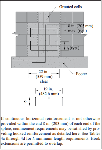
For cantilevered walls, the footing holds the wall in position and resists overturning and sliding due to lateral loads. Dowels typically extend up from the footing into the wall to transfer stresses and anchor the wall in place. Dowels should be at least equal in size and spacing to the vertical fence reinforcement. The required length of lap is determined according to the design procedure used and type of detail employed. For the design conditions listed here, the No. 4 (M#13) reinforcing bars require a minimum lap length of 15 in. (381 mm), and the No. 5 (M#16) bars require a minimum lap length of 21 in. (533 mm). Refer to TEK 12-06a, Splices, Development and Standard Hooks for Concrete Masonry (ref. 9) for detailed information on lap splice requirements.
Footings over 24 in. (610 mm) wide require transverse reinforcement (see footnotes to Table 4). For all footings, the hook should be at the bottom of the footing (3 in. (76 mm) clearance to the subgrade) in order to develop the strength of the bar at the top of the footing.
The footing designs listed in Table 4 conform with Building Code Requirements for Reinforced Concrete, ACI 318 (ref. 10). Note that concrete for footings placed in soils containing high sulfates are subject to additional requirements (refs. 1, 2).
Table 4—Footing Sizes for Cantilevered Fences
SERPENTINE WALLS
Serpentine or “folded plate” wall designs add interesting and pleasing shapes to enhance the landscape. The returns or bends in these walls also provide additional lateral stability, allowing the walls to be built higher than if they were straight.
Serpentine and folded plate walls are designed using empirical design guidelines that historically have proven successful over many years of experience. The guidelines presented here are based on unreinforced concrete masonry for lateral loads up to 20 psf (0.95 kPa). See Table 2, footnote A for corresponding wind speeds and seismic design parameters.
Design guidelines are shown in Figure 2, and include:
wall radius should not exceed twice the height,
wall height should not exceed twice the width (or the depth of curvature, see Figure 2),
wall height should not exceed fifteen times the wall thickness, and
the free end(s) of the serpentine wall should have additional support such as a pilaster or a short-radius return.
A wooden template, cut to the specified radius, is helpful for periodically checking the curves for smoothness and uniformity. Refer to TEK 5-10A, Concrete Masonry Radial Wall Details (ref. 11) for detailed information on constructing curved walls using concrete masonry units.
Figure 2—Serpentine Garden Walls
CONSTRUCTION
All materials (units, mortar, grout and reinforcement) should comply with applicable ASTM standards. Additional material requirements are listed under the section Cantilevered Fence Structural Design, above.
To control shrinkage cracking, it is recommended that horizontal reinforcement be utilized and that control joints be placed in accordance with local practice. In some cases, when sufficient horizontal reinforcement is incorporated, control joints may not be necessary. Horizontal reinforcement may be either joint reinforcement or bond beams. See CMU-TEC-009-23, Crack Control Strategies for Concrete Masonry Construction (ref. 12) for detailed guidance.
In addition, horizontal reinforcement in the top course (or courses if joint reinforcement is used) is recommended to help tie the wall together. For fences, it is not structurally necessary to provide load transfer across control joints, although this can be accomplished by using methods described in CMU-TEC-009-23 if deemed necessary to help maintain the fence alignment.
Copings provide protection from water penetration and can also enhance the fence’s appearance. Various materials such as concrete brick, cast stone, brick and natural stone are suitable copings for concrete masonry fences. Copings should project at least ½ in. (13 mm) beyond the wall face on both sides to provide a drip edge, which will help keep dripping water off the face of the fence. In cases where aesthetics are a primary concern, the use of integral water repellents in the masonry units and mortar can also help minimize the potential formation of efflorescence.
REFERENCES
2003 International Building Code. International Code Council, 2003.
2006 International Building Code. International Code Council, 2006.
Allowable Stress Design of Pier and Panel Highway Sound Barrier Walls, NCMA TEK 14-15B. Concrete Masonry & Hardscapes Association, 2004.
Design and Construction of Dry-Stack Masonry Walls, TEK 14-22. National Concrete Masonry Association, 2003.
Minimum Design Loads for Buildings and Other Structures, ASCE 7-02 and ASCE 7-05. American Society of Civil Engineers, 2002 and 2005.
Standard Specification for Loadbearing Concrete Masonry Units, ASTM C 90-01a and C 90-03. ASTM International, Inc., 2001 and 2003.
Standard Specification for Mortar for Unit Masonry, ASTM C 270-01a and C 270-04. ASTM International, Inc., 2001 and 2004.
Standard Specification for Grout for Masonry, ASTM C 476-01 and C 476-02. ASTM International, Inc., 2001 and 2002.
Splices, Development and Standard Hooks for Concrete Masonry, TEK 12-06A. Concrete Masonry & Hardscapes Association, 2007.
Building Code Requirements for Structural Concrete, ACI 318-02 and ACI 318-05. Detroit, MI: American Concrete Institute, 2002 and 2005.
Building structural design requires a variety of structural loads to be accounted for: dead and live loads, those from wind, earthquake, lateral soil pressure, lateral fluid pressure as well as forces induced by temperature changes, creep, shrinkage and differential movements. Because any load can act simultaneously with another, the designer must consider how these various loads interact on the wall. For example, an axial load can offset tension due to lateral load, thereby increasing flexural capacity, and, if acting eccentrically, can also increase the moment on the wall. Building codes dictate which load combinations must be considered, and require that the structure be designed to resist the most severe load combination.
The design aids in this TEK cover combined axial compression or axial tension and flexure, as determined using the strength design provisions of Building Code Requirements for Masonry Structures (ref. 3). For concrete masonry walls, these design provisions are outlined in Strength Design of Concrete Masonry (ref. 1). Axial load-bending moment interaction diagrams account for the interaction between moment and axial load on the design capacity of a wall. This TEK shows the portion of the interaction diagram that applies to the majority of wall designs. Although negative moments are not shown, the figures may be used for these conditions, since with reinforcement in the center of the wall wall strength will be the same under either a positive or negative moment of the same magnitude. Conditions outside of this area may be determined using Concrete Masonry Wall Design Software or Concrete Masonry Design Tables (refs. 4, 5). The reader is referred to Loadbearing Concrete Masonry Wall Design (ref. 2) for a full discussion of interaction diagrams.
Figures 1 through 8 apply to fully or partially grouted reinforced concrete masonry walls with a specified compressive strength f’m of 1,500 psi (10.34 MPa), and a maximum wall height of 20 ft (6.10 m), Grade 60 (414 MPa) vertical reinforcement, with reinforcing bars positioned in the center of the wall and reinforcing bar spacing s from 8 in. to 120 in. ( 203 to 3,048 mm). Figures 1 through 8 apply to fully or partially grouted reinforced concrete masonry walls with a specified compressive strength, f’m, of 1500 psi (10.34 MPa), and a maximum wall height of 20 ft (6.09 m), Grade 60 vertical reinforcement, with reinforcing bars positioned in the center of the wall and reinforcing bar spacing, s, from 8 in. to 120 in. ( 203 to 3,048 mm). Each figure applies to one specific wall thickness and one reinforcing bar size. For walls less than 20 ft (6.1 m) high, figures 1 through 8 will be slightly conservative due to PΔ effects.
Figure 1, Figure 2
Figure 3& Figure 4
Figure 5, Figure 6
Figure 7, Figure 8
DESIGN EXAMPLE
An 8-in. (203-mm) thick, 20 ft (6.10 m) high reinforced simply supported concrete masonry wall (115 pcf (1,842 kg/m³)) is to be designed to resist wind load as well as eccentrically applied axial live and dead loads as depicted in Figure 9. The designer must determine the reinforcement size spaced at 24 in. (610 mm) required to resist the applied loads, listed below.
D = 520 lb/ft (7.6 kN/m), at e = 0.75 in. (19 mm) L = 250 lb/ft (3.6 kN/m), at e = 0.75 in. (19 mm) W = 20 psf (1.0 kPa)
The maximum moment due to the wind load is determined as follows.
The axial load used for design is the axial load at the location of maximum moment. This combination may not necessarily be the most critical section for combined axial load and flexure, but should be close to the critical location. The wall weight is estimated to be halfway between fully grouted and hollow (82 and 38.7 psf (400 and 189 kg/m2), respectively, for 115 pcf (1842 kg/m3) unit concrete density).
The eccentricity of the axial loads also induces bending in the wall and should be included in the applied moment. The magnitude of the moment due to the eccentric axial load must be found at the same location as the maximum moment.
During design, all load combinations should be checked, with the controlling load case used for design. For brevity, only the two combinations above will be evaluated here, since the axial load actually increases the flexural capacity for the first combination by offsetting tension in the wall due to the lateral load.
Figure 2 shows that No. 4 bars at 24 in. (M #13 at 610 mm) on center are adequate. If a larger bar spacing is desired, No. 5 at 32 in. (M #16 at 813 mm) or No. 6 at 48 in. (M #19 at 1219 mm) will also meet the design requirements. Although wall design is seldom governed by out-of-plane shear, the shear capacity should be checked. In addition, the axial load should be recalculated based on the actual wall weight (based on grout spacing chosen), then the resulting required capacity should be recalculated and plotted on the interaction diagram to check adequacy.
Figure 9 -Wall Section for Loadbearing Wall Design Example
NOMENCLATURE
D dead load, lb/ft (kN/m) e eccentricity of axial load – measured from centroid of wall, in. (mm) f’m specified masonry compressive strength, psi (MPa) h height of wall, in. (mm)
L live load, lb/ft (kN/m) Lr roof live load, lb/ft (kN/m)
Mu factored moment, in.-lb/ft or ft-lb/ft (kN⋅m/m) Pu factored axial load, lb/ft (kN/m)
s spacing of vertical reinforcement, in. (mm) W wind load, psf (kN/m²) y distance measured from top of wall, ft (m)
REFERENCES
Strength Design of Concrete Masonry, TEK 14-04B. Concrete Masonry & Hardscapes Association, 2002.
Concrete masonry elements can be designed using one of several methods in accordance with Building Code Requirements for Masonry Structures (ref. 1): empirical design, strength design or allowable stress design. This TEK provides a basic overview of design criteria and requirements for concrete masonry structures designed using the strength design provisions contained in Chapter 3 of the 2002 edition of Building Code Requirements for Masonry Structures (also referred to as the MSJC Code) (ref. 1) as referenced and modified in Section 2108 of the 2003 International Building Code (IBC) (ref. 2). In addition, changes to the strength design method incorporated into the 2005 edition of the MSJC Code (ref. 3) through Section 2108 of the 2006 International Building Code (ref. 4) are also reviewed, as are modifications included in the 2008 MSJC Code (ref. 5).
For empirical and allowable stress design requirements, the user is referred to TEK 14-08B, Empirical Design of Concrete Masonry Walls (ref. 6), and TEK 14-07C, ASD of Concrete Masonry (2012 IBC & 2011 MSJC) (ref. 7), respectively. Tables, charts, and additional design aids specific to the design of various concrete masonry elements can be found in other related TEK.
Strength design is based on the following design assumptions in conjunction with basic principles of engineering mechanics (refs. 1, 3, 5), as shown in Figure 1 for a reinforced element:
Plane sections before bending remain plane after bending. Therefore, strain in the masonry and in reinforcement, if present, is directly proportional to the distance from the neutral axis.
For unreinforced masonry, the flexural stresses in the masonry are assumed to be directly proportional to strain. For reinforced masonry, the tensile strength of the masonry is neglected when calculating flexural strength, but considered when calculating deflection.
The units, mortar, grout and reinforcement for reinforced masonry act compositely to resist applied loads.
The nominal strength of masonry cross-sections for combined flexure and axial load is based on applicable conditions of equilibrium.
The maximum masonry compressive stress is 0.80f’m for both reinforced and unreinforced masonry.
The maximum usable strain, εmu, at the extreme compression fiber of concrete masonry is 0.0025.
For reinforced masonry, compression and tension stresses in the reinforcement below the specified yield strength, fy, are taken equal to the modulus of elasticity of the reinforcement, Es, times the steel strain εs. For strains greater than the yield strain corresponding to fy, stress in the reinforcement is taken equal to fy.
For reinforced masonry, the compressive stress is rectangular and uniformly distributed over an equivalent compression zone, bounded by the compression face of the masonry with a depth of a = 0.80c.
Based on the prescribed design model outlined above, the internal distribution of stresses and strains is illustrated in Figure 1 for a reinforced masonry element. A more comprehensive review of the design model is provided in Masonry Structures, Behavior and Design (ref. 8).
Figure 1—Stress and Strain Distribution for Strength Design of Reinforced Masonry
2003 IBC STRENGTH DESIGN MODIFICATIONS
The 2003 IBC adopts the 2002 MSJC Code with two modifications specific to the strength design procedure in IBC Section 2108. The two modifications are as follows.
Section 2108.2 introduces a maximum effective compression width for out-of-plane bending of six times the nominal wall thickness, not to exceed the reinforcement spacing. This is similar to limits historically used by the allowable stress design provisions in the MSJC Code as well as those adopted into the 2005 MSJC Code for strength design, as reviewed below.
Welded and mechanical splices incorporated into masonry elements designed by the strength design method must also comply with Section 2108.3 of the 2003 IBC. For welded splices, the reinforcement to be welded must comply with ASTM A 706 (ref. 9). Splicing by mechanical connectors is classified as either Type 1 or Type 2 mechanical splices in accordance with ACI 318, Building Code Requirements for Structural Concrete (ref. 10). Type 1 mechanical splices are only required to develop 125 percent of the nominal yield strength of the reinforcement being spliced. Type 2 mechanical splices, conversely, must develop the full specified tensile strength of the reinforcement. Welded and Type 1 mechanical splices are not permitted to be used in the plastic hinge region of intermediate or special reinforced masonry shear walls.
2002 MSJC CODE STRENGTH DESIGN CRITERIA
Using strength design, the design strength of a masonry element is compared to the required (or factored) strength (indicated by the subscript u), which includes load factors to account for the uncertainty in predicting design loads and the probability of more than one design load acting simultaneously. The required strength is based on the strength design load combinations as required by Section 1605 of the IBC. At the option of the designer, or when the MSJC Code is used in conjunction with another building code that does not contain load combinations, masonry structures are designed to resist the load combination specified in ASCE 7, Minimum Design Loads for Buildings and Other Structures (ref. 11). For strength design, these load combinations are effectively the same.
The design strength of masonry is the nominal strength (indicated by the subscript n) multiplied by an appropriate strength reduction factor, Φ. The design is acceptable when the design strength equals or exceeds the factored strength (i.e., when ΦMn ≥ Mu) for all prescribed load combinations. The following sections cover the general strength design requirements applicable to both unreinforced and reinforced masonry assemblies, with the exception of design requirements for anchor bolts and lap splices. For these topics, the user is referred to TEK 12-03C, Design of Anchor Bolts Embedded in Concrete Masonry (ref. 12) and TEK 12-06A, Splices, Development and Standard Hooks for CM Based on the 2009 & 2012 IBC (ref. 13), respectively.
Strength Reduction Factors
To account for uncertainties in construction, material properties, calculated versus actual strengths and anticipated failure modes, the nominal strength of a masonry element is multiplied by an appropriate strength reduction factor, Φ. Strength reduction factors are used in conjunction with the load factors applied to the design loads. The values of the strength reduction factors for various types of loading conditions are:
for reinforced masonry elements subjected to flexure or axial loads; Φ = 0.90;
for unreinforced masonry elements subjected to flexure or axial loads; Φ = 0.60;
for masonry elements subjected to shear loads; Φ = 0.80;
for bearing on masonry elements; Φ = 0.60.
Drift and Deflection
When designing for earthquakes, the story drift (the relative displacement of adjacent stories) must be checked against the IBC prescribed allowable story drifts. When the MSJC Code is used in conjunction with a building code that does not contain allowable story drifts, the provisions of ASCE 7 are used. For masonry buildings with cantilevered shear walls, the IBC limits the story drift to 0.01hsx, where hsx is the height of the story below the level for which the drift is being calculated. For other types of masonry shear wall buildings, except masonry frames, the allowable story drift is limited to 0.007hsx. While the IBC includes story drift limits for masonry frame wall buildings, such structural configurations are rarely used. When calculating story drift, the calculated elastic deflection is multiplied by the deflection amplification factor, Cd, as prescribed in the IBC for the type of structural system being designed. The deflection amplification factor approximates the additional deflection due to inelastic response (if applicable) of the system during an earthquake. Due to the inherent in-plane stiffness of masonry assemblies, in-plane deflection and story drift are rarely a controlling limit unless a relatively large number of openings is incorporated that reduces the strength and stiffness along a line of lateral resistance.
Unlike allowable stress design, which permits deflections to be calculated assuming uncracked sections for both reinforced and unreinforced masonry, strength design requires that deflections of reinforced masonry elements be based on cracked section properties, which are limited to one-half of the gross section properties unless a rigorous cracked section analysis is performed. The deflection of unreinforced masonry elements, which are required to remain uncracked, use uncracked section properties.
Because unreinforced masonry elements must be designed to remain uncracked, deflection is rarely a controlling design limit for these systems. Reinforced masonry elements, however, particularly tall, slender walls bending in the out-of-plane direction, may exhibit excessive deflection even at relatively low applied loads. As such, the MSJC Code limits the mid-height deflection, δs, of reinforced masonry elements bending in the out-of-plane direction due to service level lateral and axial loads to 0.007h. Second order effects due to P-delta contributions must also be taken into account, which is usually accomplished through iteration until convergence is achieved.
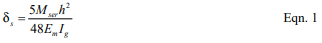
When the applied moment, Mser, is less than the moment required to cause cracking, Mcr, (Mser < Mcr) then the mid-height deflection of a masonry element subjected to a uniform out-of-plane load can be determined using Equation 1.
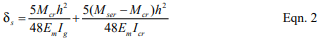
Conversely, when the applied moment, Mser, is greater than the moment required to cause cracking, Mcr, but less than the nominal moment strength of the assembly (Mcr < Mser < Mn) the mid-height deflection of a masonry element subjected to a uniform out-of-plane load can be determined using Equation 2.
The MSJC does not prescribe a method of determining the cracked moment of inertia, Icr. As such, any rational method of determining cracked section properties is permitted. CMUTEC-002-23, Weights and Section Properties of Concrete Masonry Assemblies (ref. 14), provides typical section properties for various uncracked wall sections. For use in Equations 1 and 2, the cracking moment can be taken as:
Where the modulus of rupture, fr, is obtained from Table 1 for the type of mortar and construction under consideration.
Material Properties
Due to the lack of available research data substantiating its use, the specified compressive strength of concrete masonry, f’m, designed by the strength design method is required to be at least 1,500 psi (10.34 MPa), but not larger than 4,000 psi (27.58 MPa). In addition, when used in a structural role, the specified compressive strength of grout is required to be at least equal to the specified compressive strength of concrete masonry, but not greater than 5,000 psi (34.47 MPa). For each of these upper limits on masonry assembly or grout compressive strength, the actual tested strength is permitted to exceed these values: the restriction applies only to specified strengths upon which the design is based. Note that these provisions are included in the 2005 MSJC Code as well.
Strength design of reinforced masonry is based on the specified yield strength of reinforcement, fy, which is limited to 60,000 psi (413.7 MPa). The actual yield strength of the reinforcement is limited to 1.3 times the specified yield strength. The combination of these requirements effectively precludes the use of bed joint reinforcement to be used as primary structural steel in masonry designed by the strength design method, because the nominal yield strength of bed joint reinforcement exceeds these limits. The compressive resistance of steel reinforcement is not permitted to be used unless lateral reinforcement is provided in compliance with Chapter 2 of the MSJC Code, except as permitted when checking the maximum reinforcement limits as described later.
Unreinforced Masonry
For unreinforced masonry, the masonry assembly (units, mortar and grout, if used) is designed to carry all applied stresses. The additional capacity from the inclusion of reinforcing steel, if present (such as reinforcement added to control shrinkage cracking or prescriptively required by the code), is neglected when designing unreinforced masonry elements. Because the masonry resists both tension and compression stresses resulting from applied loads, the masonry must be designed to remain uncracked.
Unreinforced Nominal Flexural Strength
The nominal flexural tensile strength of unreinforced concrete masonry is given by the modulus of rupture as prescribed in the MSJC Code, which varies with the direction of span, mortar type, bond pattern and percentage of grouting as shown in Table 1. These values apply to masonry subject to out-of-plane bending. For walls spanning horizontally between supports, the code conservatively assumes that stack bond masonry has no flexural bond strength across the mortared head joints, thus only the grout area (for horizontally grouted sections) is used. For this case, the modulus of rupture of the grout is taken equal to 250 psi (1720 kPa). Likewise, for masonry subjected to in-plane bending, the modulus of rupture normal and parallel to the bed joints is taken as 250 psi (1720 kPa).
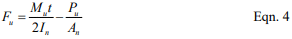
For masonry elements subjected to a factored bending moment, Mu, and a compressive axial force, Pu, the resulting flexural bending stress is determined using Equation 4.
If the resulting value of Fu is positive, then the masonry section is controlled by tension and the modulus of rupture values of Table 1, reduced by the appropriate strength reduction factor (Φ = 0.60), must be satisfied. Conversely, if Fu as given by Equation 4 is negative, the masonry section is in compression and the design compressive stress of 0.80f’m applies. When using axial load to offset flexural bending stresses as described above, only dead loads or other permanent loads should be included in Pu.
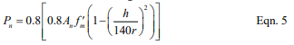
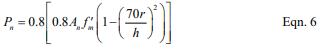
Unreinforced Nominal Axial Strength
When unreinforced masonry walls are subjected to compressive axial loads only, the nominal axial compressive strength, Pn, is determined using equation 5 or 6, as appropriate. Unreinforced masonry is not permitted to carry net axial tension forces.
For elements with h/r not greater than 99:
For elements with h/r greater than 99:
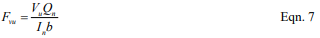
Unreinforced Nominal Shear Strength
Shear stresses on unreinforced masonry elements are calculated using the net cross-sectional properties of the masonry in the direction of the applied shear force using:
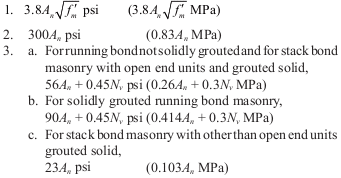
Equation 7 is applicable to determining both in-plane and out-of-plane shear stresses. Because unreinforced masonry is designed to remain uncracked, it is not necessary to perform a cracked section analysis to determine the net section properties. In turn, the applied shear stresses (factored accordingly for the appropriate load combination) are compared to the nominal shear strength, Vn, of an unreinforced masonry section, which is the least of:
Table 1—Modulus of Rupture Values, psi (kPa)
Reinforced Masonry
The design of reinforced masonry in accordance with the MSJC Code neglects the tensile resistance provided by the masonry units, mortar and grout in determining the strength of the masonry assemblage. (The tensile strength of the units, mortar, and grout is considered, however, in determining the stiffness and deflection of a reinforced masonry element.) Thus, for design purposes, the portion of masonry subject to net tensile stress is assumed to have cracked, transferring all tensile forces to the reinforcement.
Using strength design, reinforcing bars used in masonry may not be larger than No. 9 (M #29) and bars may not be bundled. Further, the nominal bar diameter is not permitted to exceed one-eighth of the nominal member thickness or one-quarter of the least clear dimension of the cell, course or collar joint in which it is placed. The total area of reinforcing bars placed in a single cell or in a course of hollow unit construction may not exceed 4% of the cell area. Note that this limit does not apply at sections where lap splices occur. At lap splices, the maximum reinforcing bar area is increased to 8%, in both the 2002 and 2005 editions of the MSJC Code.
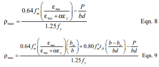
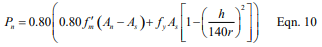
Maximum Flexural Reinforcement Ratio
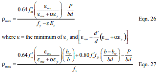
To provide for a prescribed level of reinforced masonry ductility in the event of failure, the maximum reinforcement ratio, ρmax, is limited in accordance with Equation 8 or 9, as appropriate. Equation 8 applies to masonry cross sections that are fully grouted or where the neutral axis falls within the face shell of the masonry units in partially grouted construction. When the neutral axis falls within the cores of partially grouted construction, Equation 9 is used.
The tension reinforcement yield strain factor, α, varies with the seismic response modifi cation factor, R, masonry element, and type of loading as follows:
α = 1.3 for walls subjected to out-of-plane forces and designed using an R value greater than 1.5,
α = 5.0 for walls subjected to in-plane forces, for columns and for beams designed using an R > 1.5,
α = 2.0 for masonry structures designed using an R ≤ 1.5.
In the above set of requirements, R is larger for out-of-plane loads when R is less than or equal to 1.5, which is contrary to the underlying intent of providing increased ductility for systems and elements whose ductility demand may be relatively high. Several updates and revisions to the maximum have been incorporated into subsequent editions to the 2002 MSJC Code as reviewed below.
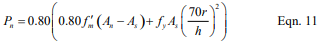
Reinforced Nominal Axial Strength
The nominal axial strength, Pu, of masonry walls, piers and columns, modified to account for the effects of slenderness, is determined using equation 10 or 11, as appropriate. The MSJC Code also limits the factored axial stress to 0.20f’m.
For elements with h/r not greater than 99:
For elements with h/r greater than 99:
Note that the reinforcing steel area, As, is included in the nominal axial strength calculation only if it is laterally confined in accordance with Chapter 2 of the MSJC Code.
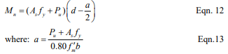
Reinforced Nominal Flexural Strength
The nominal flexural strength, Mn, of a reinforced masonry element is determined as outlined below. In addition, the nominal flexural strength at any section along a member must be at least one-fourth of the maximum nominal flexural strength at the critical section.
When there are no axial loads, or when axial loads are conservatively neglected as may be appropriate in some cases, there are several circumstances to consider when determining the nominal flexural strength of reinforced masonry walls. For a fully grouted element, the internal moment arm between the resulting compressive and tensile forces is resolved to determine the resisting capacity of the section. Partially grouted walls are analyzed in the same way, but with the additional consideration of the possible influence of the ungrouted cores on the strength of the section. For partially grouted masonry bending out-of-plane, there are two types of behavior to consider.
In the first case, when the neutral axis (the location of zero stress) lies within the compression face shell, the wall is analyzed and designed using the procedures for a fully grouted wall.
In the second case, when the neutral axis lies within the core area, the portion of the ungrouted cells must be deducted from the area of masonry capable of carrying compression stresses.
The neutral axis location depends on the reinforcement spacing as well as the reinforcement ratio, ρ, and the distance between the reinforcement and the extreme compression fiber, d.
When analyzing partially grouted walls, it is typically initially assumed that the neutral axis lies within the compression face shell, as the analysis is more straightforward. The value of c is then calculated based on this assumption. If it is determined that the neutral axis lies outside the compression face shell, the more rigorous tee beam analysis is performed. Otherwise, the rectangular beam analysis is carried out.
Rectangular Beam Analysis
For fully grouted masonry elements and for partially grouted masonry walls with the neutral axis in the compression face shell, the nominal flexural strength, Mn, is calculated using equations 12 and 13 as follows:
Tee Beam Analysis
For partially grouted masonry walls where the neutral axis is located within the cores, the nominal flexural strength, Mn, is calculated using equations 14, 15, and 16 as follows:
To account for deflection resulting from out-of-plane loads and the additional bending moment due to eccentrically applied axial loads, the factored bending moment at the mid-height of a simply supported wall under uniform loading is required to be determined by Equation 17.
Multiple iterations may be necessary to determine the converging value of the resulting deflection.
Reinforced Nominal Shear Strength
Shear acting on reinforced masonry members is resisted by the masonry and shear reinforcement, if provided, in accordance with the following:
Where Vn may not exceed the values given by Equations 20 or 21, as appropriate.
Where M/Vdv is less than or equal to 0.25:
Where M/Vdv is greater than 1.00:
For values of M/Vdv between 0.25 and 1.00, the maximum value of Vn may be linearly interpolated.
The nominal shear strength provided by the masonry is determined in accordance with the following.
Where the value of M/Vdv need not be taken greater than 1.0.
When shear reinforcement is incorporated into reinforced masonry construction, the shear strength provided by the reinforcement is calculated in accordance with the following.
2006 IBC REQUIREMENTS
The following is a brief summary of the changes and modifications adopted into the 2005 MSJC Code as referenced in the 2006 IBC. The majority of the basic design provisions remain unchanged, with several notable exceptions as reviewed below.
2006 IBC Strength Design Modifications
The same modifications for welded and mechanical splices previously discussed in the 2003 IBC Strength Design Modifications section remain in the 2006 IBC. In addition, Section 2108 of the 2006 IBC has incorporated a limit of 72db on the maximum required length of lap splices used in masonry designed by the strength design method as determined by the 2005 MSJC lap splice provisions. While this limit is typically not triggered for relatively small bar diameters, it can reduce the required lap length of large diameter reinforcing bars or in cases where small cover distances are used. Refer to TEK 12-06A (ref. 13) for detailed splice length requirements.
Other changes to Section 2108 of the 2006 IBC reflect updates and modifications to the 2005 MSJC Code to remove redundant or conflicting requirements.
Due primarily to oversight, the 2002 MSJC Code did not include explicit provisions for determining the bearing strength of masonry subjected to concentrated loads. The bearing strength requirements adopted into the 2005 MSJC Code are similar to those used for allowable stress design, modified as necessary for use in strength design. The nominal bearing strength of masonry is taken as the greater of Equations 24 and 25:
The value of 0.6 in Equations 24 and 25 is a design coefficient, not the strength reduction factor, Φ, which also happens to be equal to 0.6 for determining the design bearing strength. For use in Equation 25, the following expression must also be satisfied:
Where A1 is the actual bearing area directly under the bearing plate and A2 is the effective bearing area, defined as a right o pyramid having A1 as a top plane and sloping at 45 . For walls laid in stack bond, the area defined by A2 is terminated at head joints unless a bond beam or other means of distributing stresses is used. The concentrated stresses are distributed over a length equal to the width of the bearing area plus four times the thickness of the supporting element, but not to exceed the center-to-center distance between the concentrated loads.
Modulus of Rupture
The 2005 MSJC Code incorporated a few modifications to the modulus of rupture values presented in Table 1 for flexural tension stresses normal to the bed joints of hollow, fully grouted assemblies, as shown in Table 2. These modifications recognize that the type of mortar has less of an influence on the modulus of rupture when the element is fully grouted.
In addition, instead of prescribing a single value of 250 psi (1.72 MPa) for masonry subjected to in-plane bending as in the 2002 MSJC Code, the 2005 MSJC Code requires the use of Table 1, as modified by Table 2, for all cases of in-plane and out-of-plane bending.
Table 2—Modifi cations to Modulus of Rupture Values in Table 1, as Included in the 2005 MSJC Code, psi (kPa)
Maximum Flexural Reinforcement Limits
The maximum flexural reinforcement requirements in the 2005 MSJC employ the same strain gradient approach as reviewed above, with several notable revisions.
Reinforcement is permitted to carry compression stresses, with or without lateral confining reinforcement. Further, the 1.25 factor on the nominal yield stress of the reinforcement as been removed. The resulting equations for the maximum flexural reinforcement limits are given by Equation 26 for fully grouted members or members subjected to in-plane loads, and Equation 27 for partially grouted masonry assemblies subjected to out-of-plane loads where the neutral axis falls in an open cell.
The tension reinforcement yield strain factor, α, is taken equal to the following values when Mu/Vudv ≥ 1.0 (indicating performance is dominated by flexure):
for intermediate reinforced masonry shear walls subjected to in-plane loads: α = 3.0,
for special reinforced masonry shear walls subjected to in-plane loads: α = 4.0,
for other masonry elements and loading conditions: α= 1.5.
For cases where Mu/Vudv ≤ 1.0 (indicating shear dominated performance) and R > 1.5: α = 1.5.
For masonry members where Mu/Vudv ≤ 1.0 and R ≤ 1.5, there is no limit on the amount of reinforcement permitted.
The axial load, P, for use in Equations 26 and 27, is the gravity axial load component determined from the following load combination: D + 0.75L + 0.525QE.
Effective Compression Width per Reinforcing Bar
Section 2108 of the 2003 IBC included limits on the effective compression width per reinforcing bar, which were subsequently removed from the 2006 IBC, as similar provisions were incorporated into the 2005 MSJC Code. For masonry construction in running bond, and for masonry in stack bond construction with bond beams space no further than 48 in. (1,219 mm) on center, the maximum width of the compression area used is limited to the least of:
the center-to-center spacing of the reinforcement;
six times the nominal thickness of the element; or
72 in. (1,829 mm).
Boundary Elements
New to the 2005 MSJC Code are design provisions for boundary elements incorporated into the end zones of masonry shear walls. Because the MSJC does not include minimum prescriptive reinforcement detailing requirements for boundary elements, it requires that when used, their performance be verified by testing. In addition, when meeting the requirements for geometrical symmetry, axial load and flexural performance, the MSJC Code permits the maximum reinforcement limits as reviewed above to be waived. This exception may or may not require the incorporation of special boundary elements, depending on the design circumstances.
2008 MSJC STRENGTH DESIGN REQUIREMENTS
At the time of publication, the 2008 edition of the MSJC Code had been finalized, but the 2009 edition of the IBC had not. In anticipation of the 2009 IBC adopting the 2008 MSJC by reference, following is a brief overview of changes to the strength design provisions of the 2008 MSJC Code. In addition to some reorganization, substantive revisions to the strength design method include:
The shear strength check to help preclude brittle failure of a masonry element during an earthquake was revised to apply only to special reinforced masonry shear walls. Previously, this check applied to both reinforced and unreinforced masonry elements regardless of seismic considerations.
The requirement to provide at least 80 percent of the lateral stiffness through shear walls was revised to apply only to Seismic Design Categories C and higher.
Instead of requiring that the deflection of all reinforced masonry elements be calculated on cracked section properties, the 2008 MSJC Code simply requires that the design “consider the effects of cracking and reinforcement on member stiffness,” thereby permitting more flexibility in design application.
A moment magnifier approach was incorporated for unreinforced masonry design in determining the influence of P-delta effects. The magnified moment, Mc, is determined either through a second-order analysis, or by the following:
For members with h/r ≤ 45, it is permitted to take δ = 1.0. For members with 45 < h/r ≤ 60, it is permitted to take δ = 1.0 provided that the maximum factored axial stress on the element does not exceed 0.72f’m.
NOTATIONS
An = net cross-sectional area of masonry, in.² (mm²) As = effective cross-sectional area of reinforcement, in.² (mm²) Av = cross-sectional area of shear reinforcement, in.² (mm²) A1 = bearing area under bearing plate, in.² (mm²) A2 = effective bearing area, in.² (mm²) a = depth of an equivalent compression zone at nominal strength, in. (mm) b = width of section, in. (mm) bw = for partially grouted walls, width of grouted cell plus each web thickness within the compression zone, in. (mm) C = resultant compressive force, lb (N) c = distance from the fiber of maximum compressive strain to the neutral axis, in. (mm) Cd = seismic deflection amplification factor Cn = nominal bearing strength, lb (N) D = dead load, lb (N) d = distance from the extreme compression fiber to centroid of tension reinforcement, in. (mm) db = nominal diameter of reinforcement, in. (mm) dv = actual depth of masonry in direction of shear considered, in. (mm) d’ = distance from the extreme tension fiber to centroid of compression reinforcement, in. (mm) Em = modulus of elasticity of masonry, psi (MPa) Es = modulus of elasticity of reinforcement, psi (MPa) eu = eccentricity of Puf in. (mm) Fu = net flexural bending stress due to factored loads, psi (MPa) Fvu = shear stress on unreinforced masonry elements, psi (MPa) f’m = specified compressive strength of masonry, psi (MPa) fr = modulus of rupture, psi (MPa) fy = specified yield strength of reinforcement, psi (MPa) h = effective height of masonry element, in. (mm) hsx = effective height of masonry element below level x, in. (mm) Icr = moment of inertia of cracked cross-sectional area of a member, in.4 (mm4) Ig = moment of inertia of gross cross-sectional area of a member, in.4 (mm4) In = moment of inertia of net cross-sectional area of a member, in.4 (mm4) L = live load, lb (N) M = unfactored maximum calculated bending moment at the section under consideration, in.-lb (N-mm) Mc = factored moment magnified for the effects of member curvature, in.-lb (N-mm) Mcr = cracking bending moment, in.-lb (N-mm) Mn = nominal moment strength, in.-lb (N-mm) Mser = applied bending moment, in.-lb (N-mm) Mu = factored moment, in.-lb (N-mm) Nv = compressive force acting normal to the shear surface, lb (N) P = unfactored axial load, lb (N) Pn = nominal axial strength, lb (N) Pu = factored axial load, lb (N) Puf = factored load from tributary floor or roof areas, lb (N) Puw = factored weight of wall area tributary to wall section under consideration, lb (N) QE = the effect of horizontal seismic forces, lb (N) Qn = first moment about the neutral axis of a section of that portion of the net cross section lying between the neutral axis and extreme fiber, in.³ (mm³) R = seismic response modification factor r = radius of gyration, in. (mm) Sn = section modulus of cross-section, in.³ (mm³) s = spacing of shear reinforcement, in. (mm) T = tension in reinforcement, lb (N) t = specified thickness of masonry element, in. (mm) tfs = concrete masonry face shell thickness, in. (mm) V = unfactored shear force, lb (N) Vm = shear strength provided by masonry, lb (N) Vn = nominal shear strength, lb (N) Vs = shear strength provided by shear reinforcement, lb (N) Vu = factored shear, lb (N) wu = out-of-plane factored uniformly distributed load, lb/in. (N/mm) X = for partially grouted masonry, distance from extreme compression fiber to centroid of the compression resultant, in. (mm) α = tension reinforcement yield strain factor δ = moment magnification factor δs = deflection due to service loads, in. (mm) δu = deflection due to factored loads, in. (mm) εmu = maximum usable compressive strain of masonry εs = steel strain εy = yield strain of reinforcement ρ = reinforcement ratio ρmax = maximum reinforcement ratio Φ = strength reduction factor
REFERENCES
Building Code Requirements for Masonry Structures, ACI 530-02/ASCE 5-02/TMS 402-02. Reported by the Masonry Standards Joint Committee, 2002.
2003 International Building Code. International Code Council, 2003.
Building Code Requirements for Masonry Structures, ACI 530-05/ASCE 5-05/TMS 402-05. Reported by the Masonry Standards Joint Committee, 2005.
2006 International Building Code. International Code Council, 2006.
Building Code Requirements for Masonry Structures, ACI 530-08/ASCE 5-08/TMS 402-08. Reported by the Masonry Standards Joint Committee, 2008.
Empirical Design of Concrete Masonry Walls, TEK 1408B, Concrete Masonry & Hardscapes Association, 2008.
ASD of Concrete Masonry (2012 IBC & 2011 MSJC), TEK 14-07C, Concrete Masonry & Hardscapes Association, 2004.
Drysdale, R. G., Hamid, A. A. and Baker L. R., Masonry Structures, Behavior and Design, Second Edition. The Masonry Society, 1999.
Standard Specification for Low-Alloy Steel Deformed and Plain Bars for Concrete Reinforcement, ASTM A 706/A 706M-01. ASTM International, 2001.
Building Code Requirements for Structural Concrete, ACI 318-02. American Concrete Institute, 2002.
Minimum Design Loads for Buildings and Other Structures, ASCE 7-02. Structural Engineering Institute of the American Society of Civil Engineers, 2002.
Design of Anchor Bolts Embedded in Concrete Masonry, TEK 12-03C. Concrete Masonry & Hardscapes Association, 2013.
Splices, Development and Standard Hooks for CM Based on the 2009 & 2012 IBC, TEK 12-06A, Concrete Masonry & Hardscapes Association, 2013.
Weights and Section Properties of Concrete Masonry Assemblies, CMU-TEC-002-23, Concrete Masonry & Hardscapes Association, 2023.
Building codes include requirements for minimum reinforcement development lengths and splice lengths, as well as requirements for standard hooks, to ensure the adequate transfer of stresses between the reinforcement and the masonry. This TEK presents these requirements, based on the provisions of both the 2012 and 2009 editions of the International Building Code (IBC) (refs. 1, 2). Masonry design in these codes is primarily based on Building Code Requirements for Masonry Structures (MSJC) (refs. 3, 4). Differences between the MSJC and IBC are noted in the text when they occur.
There are two main differences between the 2008 and 2011 editions of the MSJC that impact reinforcement development and splice lengths in the corresponding 2009 and 2012 editions of the IBC:
under 2011 MSJC allowable stress design, the allowable tensile stress, Fs, of Grade 60 steel was increased from 24,000 psi (166 MPa) to 32,000 psi (221 MPa), and
the 2011 MSJC includes new lap splice length provisions for when confinement reinforcement is used at lap splices.
TEK 12-04D (ref. 5) includes basic material requirements, corrosion protection and placement tolerances for reinforcement used in concrete masonry construction. In addition, prestressing steel is discussed in Post-Tensioned Concrete Masonry Wall Construction, TEK 03-14 (ref. 6).
SPLICES AND DEVELOPMENT LENGTH
Minimum development lengths are necessary to adequately transfer stresses between reinforcement and the grout or mortar in which it is embedded. Splicing of reinforcement serves a similar purpose: to adequately transfer stresses from one reinforcing bar to another.
Reinforcement can be developed by embedment length, hook, or mechanical anchoring device. The development of the reinforcing bars relies on mechanical interlock of the bar deformations, hook, and/or anchor along with sufficient masonry cover to prevent splitting of the masonry. Reinforcing bars may be spliced by lapping the reinforcement, by proprietary mechanical splices or by welding.
The required length of lap or development is determined according to the design procedure used (allowable stress design or strength design). In addition, these detailing requirements have been frequently revised in recent years. As a result, the minimum lap and development lengths can vary considerably from one code to the next as well as from one design method to another.
The following sections present the requirements for both the 2009 IBC and 2012 IBC for both allowable stress and strength design.
2009 IBC SPLICE & DEVELOPMENT REQUIREMENTS
2009 IBC Allowable Stress Design
Development Length & Lap Splicing
While the 2008 MSJC includes an equation to determine development and lap splice lengths, the 2009 IBC modifies the MSJC lap splice length. In accordance with the 2009 IBC, the minimum required lap length for spliced reinforcing bars is determined using Equation 1 (see Table 1).
but not less than 12 in. (305 mm) or 40db, whichever b is greater
Further, in regions of flexure where the design tensile stresses in the reinforcement, fs, exceed 80% of the allowable steel tensile stress, Fs, the IBC requires that the required length of lap determined by Equation 1 must be increased by 50%. Alternatively, equivalent means of stress transfer to accomplish the same 50% increase is permitted. Where epoxy coated bars are used, lap length is also required to be increased by 50% but does not apply to the 12 in. (305 mm) minimum.
Development length requirements for allowable stress design are determined in accordance with Equation 3 except that there is no maximum length limit of 72db.
When noncontact lap splices are used, the bars must be spaced no farther apart than one-fifth the required length of lap nor more than 8 in. (203 mm).
When using the allowable stress design method, development of wires in tension is determined using Equation 2 (see Table 2). The development length of epoxy-coated wires is increased 50% above the value determined using Equation 2 but does not apply to the 6 in. (152 mm) minimum.
Table 2—2009 & 2012 IBC Allowable Stress Design Development Lengths for Wire (refs. 1, 2) (A)
A See Equation 2. fs = 30,000 psi (207 MPa). Lap splice length not less than 6 in. (152 mm). Increase development lengths by 50% when epoxy coated wire is used, but this increase does not apply to the 6 in. (152 mm) minimum..
Alternatives to Lap Splicing
Reinforcing bars can also be spliced by welding, mechanical splicing and in some cases end-bearing splicing. Reinforcing bars larger than No. 9 (M#29) are required to be spliced using mechanical connectors.
Welded splices require the bars to be butted or shortly lapped and welded to develop in tension at least 125% of the specified yield strength of the bar. All welding is required to conform to AWS D1.4 (ref. 7), and steel for welded splices must conform to ASTM A706 (ref. 8). In practice, however, welding tends to be an expensive splicing option.
Mechanical splicing of reinforcement typically employs proprietary couplers specifically designed for this application. Mechanical splices are required to have the bars connected to develop in tension or compression, as required, at least 125% of the specified yield strength of the bar.
Reinforcing bars can also be spliced using end-bearing splices, but only in members containing closed ties, closed stirrups or spirals for bars subject to compression only. End-bearing splices rely on the transmission of compressive stress by bearing of square-cut ends held in concentric contact by a suitable device. The bar ends are required to terminate in flat surfaces within 11/2 degrees of a right angle to the axis of the bars and be fitted within 3 degrees of full bearing after assembly.
2009 IBC Strength Design
Development Length & Lap Splice Length
For development and lap splice length requirements, the 2009 IBC references the 2008 MSJC (see Equation 3 and Table 3), but adds a maximum length limit of 72db.
For Equation 3, the reinforcement size factor, g, is taken equal to 1.0 for No. 3 through No. 5 (M#10–M#16) reinforcing bars; 1.3 for No. 6 and No. 7 (M#19, M#22) bars; and 1.5 for No. 8 and No. 9 (M#25, M#29) bars. When epoxy coated bars are used, the development length determined by Equation 3 is required to be increased by 50%.
Bars spliced by noncontact lap splices must be spaced no farther apart than one-fifth the required length of lap and no more than 8 in. (203 mm).
Alternatives to Lap Splicing
Mechanical splices are required to have the bars connected to develop at least 125% of the specified yield strength of the bar in tension or compression, as required.
The IBC further stipulates that mechanical splices be classified as Type 1 or 2 according to Section 21.2.6.1 of ACI 318, Building Code Requirements for Structural Concrete and Commentary (ref. 10). Type 1 splices may not be used within the plastic hinge zone nor within a beam-column joint of intermediate or special reinforced masonry shear walls or special moment frames. Type 2 are permitted at any location.
A Type 2 splice is defined as a full mechanical splice that develops in tension or compression, as required, at least 1.25fy of the bar. This requirement is intended to avoid a splice failure when the reinforcement is subjected to expected stress levels in yielding regions. Type 1 splices are not required to satisfy the more stringent requirements for Type 2 splices, and so their use is limited as noted above.
Welded splices must have the bars butted and welded to develop at least 125% of the bar’s specified yield strength in tension or compression, as required. Welded splices must use ASTM A706 (ref. 9) steel reinforcement. Welded splices are not permitted to be used in plastic hinge zones of intermediate or special reinforced walls nor in special moment frames of masonry.
2012 IBC SPLICE & DEVELOPMENT REQUIREMENTS
Regarding development and splice lengths, two significant changes were incorporated into the 2011 MSJC, which are included by reference in the 2012 IBC:
in the 2011 MSJC, the allowable tensile stress, Fs, of Grade 60 steel when using allowable stress design was increased from 24,000 psi (166 MPa) to 32,000 psi (221 MPa), and
the 2011 MSJC includes new provisions for confinement reinforcement, for both allowable stress and strength design methods.
2012 IBC Allowable Stress Design
Equation 1 is still applicable for use in the 2012 IBC but with the increase in F the splice lengths of fully stressed bars will increase by 33%. Significant reductions of splice lengths in low stress areas are achieved, however. The minimums of 12 in. (305 mm) or 40db whichever is greater still apply as well.
The 2012 IBC allows the MSJC development length equation (Equation 3) to be used as an alternate to the IBC equation (Equation 1). When using Equation 3 under the 2012 IBC, however, the value of K is defined as the least of the masonry cover, 9db (vs. 5db in the 2009 IBC) and the clear spacing between adjacent reinforcement.
Tabulated values are presented in Tables 4a through 4d. Note, however, that there is no maximum length limit of 72db for allowable stress design.
Tables 4a and 4b present minimum lap splice lengths for reinforcement placed in the center of the wall, for f’m = 1,500 and 2,000 psi (10.3 and 13.7 MPa), respectively.
Tables 4c and 4d present minimum lap splice lengths for reinforcement offset in the wall, for f’m = 1,500 and 2,000 psi (10.3 and 13.7 MPa), respectively.
Other requirements for lap, mechanical, welded and end-bearing splices are identical to those under the 2009 IBC, with the exception of the new provisions for confinement reinforcement, presented below.
2012 IBC Strength Design
Requirements for development length as well as lap, mechanical and welded splices are identical to those for allowable stress design, and are presented in Tables 4a through 4d.
2012 IBC Lap Splices With Confinement Reinforcement
The 2012 IBC, by reference to the 2011 MSJC, includes new lap splice criteria where confinement reinforcement is placed. The criteria are the same for both allowable stress design and strength design.
The confinement reinforcement criteria allow a reduced lap splice length when reinforcement is provided transverse to lapped bars. Research has found that the transverse, or confinement, reinforcement increases the lap performance significantly, as long as there is at least one No. 3 (M#10) or larger transverse bar placed within the last 8 in. (203 mm) of each end of the lap (see Figure 1). Because of this effect, calculated lap splice lengths are permitted to be reduced by a confinement factor, ξ, determined using Equation 4:
where
db is the bar diameter of the vertical reinforcement
The reduced lap splice length is not permitted to be less than 36db. The clear space between the transverse bars and the lapped bars may not exceed 1.5 in. (38 mm), and the transverse bars must be fully developed in grouted masonry at the point where they cross the lapped reinforcement (see Figure 1). These provisions are included in Tables 4a through 4d
Table 3—2009 IBC Strength Design Lap Splice Lengths (ref. 2)A
Figure 1—Confinement Reinforcement at Lap Splice
Table 4a—2012 IBC Lap Splice Lengths, f’m = 1,500 psi (10.3 MPa), Reinforcement in Center of Wall (ref. 1)A
Table 4b—2012 IBC Lap Splice Lengths, f’m = 2,000 psi (13.7 MPa), Reinforcement in Center of Wall (ref. 1)A
Figure 2 illustrates the requirements for standard hooks, when reinforcing bars are anchored by hooks or by a combination of hooks and development length. These requirements apply to both the 2009 and 2012 IBC, for both allowable stress and strength design. Table 5 lists minimum dimensions and equivalent embedment lengths for standard hooks of various sizes. A combination of hook and development length must be used when the equivalent embedment length of the hook, le, is less than the required minimum development length, ld. In this case, development length equal to (ld – le) must be provided in addition to the hook. This additional development length is measured from the start of the hook (point of tangency with the main portion of the bar).
Figure 2—Standard Hooks
Table 5—Standard Hooks—Dimensions and Equivalent Embedment Lengths
JOINT REINFORCEMENT SPLICES
Joint reinforcement must have a minimum splice length of 6 in. (152 mm) to transfer shrinkage stresses. Slippage of the deformed side wires is resisted by surface bond as well as by mechanical anchorage of the embedded portions of the cross wires.
NOTATIONS:
Asc = area of the transverse bars at each end of the lap splice, in.² (mm²) Di = min. inside diameter of bend for standard hooks, in. (mm) db = nominal diameter of reinforcement, in. (mm) K = the least of the masonry cover, 9db for the 2012 IBC (5db for the 2009 IBC) and the clear spacing between adjacent reinforcement, in. (mm) Fs = allowable tensile stress in reinforcement, psi (MPa) f’m = specified compressive strength of masonry, psi (MPa) fs = calculated tensile or compressive stress in steel, psi (MPa) fy = specified yield strength of steel, psi (MPa) ld = embedment length or lap splice length of straight reinforcement, in. (mm) le = equivalent embedment length provided by standard hooks measured from the start of the hook (point of tangency), in. (mm) lt = length of bar extension of hooked confinement reinforcement, in. (mm) γ = reinforcement size factor ξ = lap splice confinement reinforcement factor
REFERENCES
International Building Code 2012. International Code Council, 2012.
International Building Code 2009. International Code Council, 2009.
Building Code Requirements for Masonry Structures, TMS 402-11 /ACI 530-11/ASCE 5-11. Reported by the Masonry Standards Joint Committee, 2011.
Building Code Requirements for Masonry Structures, TMS 402-08 /ACI 530-08/ASCE 5-08. Reported by the Masonry Standards Joint Committee, 2008.
Steel Reinforcement for Concrete Masonry, TEK 12-04D. Concrete Masonry & Hardscapes Association, 2007.
Structural Welding Code—Reinforcing Steel, AWS D 1.4-05. American Welding Society, 2005.
Standard Specification for Low-Alloy Steel Deformed and Plain Bars for Concrete Reinforcement, ASTM A706/A706M-09b. ASTM International, Inc., 2009.
Building Code Requirements for Structural Concrete and Commentary, ACI 318-11. American Concrete Institute, 2011.
TEK 12-06A, Revised 2013. CMHA and the companies disseminating this technical information disclaim any and all responsibility and liability for the accuracy and the application of the information contained in this publication.
Reinforcement in concrete masonry walls increases strength and ductility, increases resistance to applied loads, and in the case of horizontal reinforcement, also provides increased resistance to shrinkage cracking. This TEK covers non-prestressed reinforcement for concrete masonry construction. Prestressing steel is discussed in Post-Tensioned Concrete Masonry Wall Construction, TEK 03-14 (ref. 1). Unless otherwise noted, the information is based on the 2003 International Building Code (IBC) (ref. 2). For masonry design and construction, the IBC references Building Code Requirements for Masonry Structures and Specification for Masonry Structures (MSJC Code and Specification) (refs. 4, 5). In some cases, the IBC has adopted provisions different from the MSJC provisions. These instances have been noted where applicable.
MATERIALS
Reinforcement used in masonry is principally reinforcing bars and cold-drawn wire products. Wall anchors and ties are usually formed of wire, metal sheets or strips. Table 1 lists applicable ASTM Standards governing steel reinforcement, as well as nominal yield strengths for each steel type.
Table 1—Reinforcement Used in Masonry (ref. 2)
Reinforcing Bars
Reinforcing bars are available in the United States in 11 standard bar sizes designated No. 3 through 11, No. 14 and No. 18 (M#10-36, M#43, M#57). The size of a reinforcing bar is designated by a number corresponding to its nominal diameter. For bars designated No. 3 through No. 8 (M#10-25), the number indicates the diameter in eighths of an inch (mm), as shown in Table 2.
To help address potential problems associated with reinforcement congestion and grout consolidation, the IBC limits the reinforcing bar diameter to the lesser of one-eighth the nominal member thickness, and one-fourth the least dimension of the cell, course or collar joint into which it is placed. For typical single wythe walls, this corresponds to a maximum bar size of No. 8, 9 and 11 for 8-, 10- and 12- in. walls, respectively (M#25, 29 and 36 for 203-, 254- and 305-mm walls). In addition, the following limits apply:
maximum bar size is No. 11 (M#36),
the area of vertical reinforcement may not exceed 6% of the grout space area (i.e., about 1.26 in.² , 1.81 in.² , or 2.40 in.² of vertical reinforcement for 8-, 10- and 12-in. concrete masonry, respectively (815, 1,170 or 1,550 mm² for 203-, 254- and 305-mm units, respectively), and
for masonry designed using strength design procedures, the maximum bar size is No. 9 (M#29) and the maximum area of reinforcement is 4% of the cell area (i.e., about 0.84 in.² , 1.21 in.² , or 1.61 in.² of vertical reinforcement for 8-, 10- and 12-in. concrete masonry, respectively (545, 781 or 1,039 mm² for 203-, 254- and 305-mm units, respectively).
The prescriptive limits on reinforcement sizes, above, are construction-related. Additional design limits to prevent over-reinforcing and brittle failures may also apply depending on the design method used and the design loads resisted. Manufacturers mark the bar size, producing mill identification and type of steel on reinforcing bars (see Figure 1). Note that the bar size indicates the size in SI units per ASTM standards.
The ASTM standards include minimum requirements for various physical properties including yield strength and stiffness. While not all reinforcing bars have a well-defined yield point, the modulus of elasticity, Es , is roughly the same for all reinforcing steels and for design purposes is taken as 29,000,000 psi (200 GPa).
When designing by the allowable stress design method, allowable tensile stress is limited to 20,000 psi (138 MPa) for Grade 40 or 50 reinforcing bars and 24,000 psi (165 MPa) for Grade 60 reinforcing bars. For reinforcing bars enclosed in ties, such as those in columns, the allowable compressive stress is limited to 40% of the specified yield strength, with a maximum of 24,000 psi (165 MPa). For strength design, the nominal yield strength of the reinforcement is used to size and distribute the steel.
Table 2—Reinforcing Bar Nominal Properties
Figure 1—ASTM Standard Bar Identifi cation Marks
Cold-Drawn Wire
Cold-drawn wire for joint reinforcement, ties or anchors varies from W1.1 to W4.9 (MW7 to MW32) with the most popular size being W1.7 (MW11). Table 3 shows standard wire sizes and properties. Because the IBC limits the size of joint reinforcement to one half the joint thickness, the practical limit for wire diameter is 3/16 in. (W2.8, 4.8 mm, MW18) for a ⅜ in. (9.5 mm) bed joint. Wire for masonry is plain with the exception that side wires for joint reinforcement are deformed by means of knurling wheels.
Stress-strain characteristics of reinforcing wire have been determined by extensive testing programs. Not only is the yield strength of cold-drawn wire close to its ultimate strength, but the location of the yield point is not clearly indicated on the stress-strain curve. ASTM A 82 (ref. 15) defines yield as the stress determined at a strain of 0.005 in./in. (mm/mm).
Table 3—Properties of Wire For Masonry
CORROSION PROTECTION
Grout, mortar and masonry units usually provide adequate protection for embedded reinforcement provided that minimum cover and clearance requirements are met. Reinforcement with a moderate amount of rust, mill scale or a combination is allowed to be used without cleaning or brushing, provided the dimensions and weights (including heights of deformations) of a cleaned sample are not less than those required by the applicable ASTM standard. When additional corrosion protection is needed, reinforcement can be galvanized or epoxy coated.
Joint Reinforcement
Carbon steel can be protected from corrosion by coating the steel with zinc (galvanizing). The zinc protects in two ways: first, as a barrier separating the steel from oxygen and water, and second during the corrosion process, the zinc is sacrificed before the steel is attacked. Increasing the zinc coating thickness improves the level of corrosion protection.
Required levels of corrosion protection increase with the severity of exposure. When used in exterior walls or in interior walls exposed to a mean relative humidity over 75%, carbon steel joint reinforcement must be hot-dip galvanized or epoxy-coated, or stainless steel joint reinforcement must be used. When used in interior walls exposed to a mean relative humidity less than or equal to 75%, it can be mill galvanized, hot-dip galvanized, or be stainless steel. The corresponding minimum protection levels are:
Mill galvanized—ASTM A 641 (ref. 16) 0.1 oz/ft² (0.031 kg/m²)
Hot-dip galvanized—ASTM A 153 (ref. 17), Class B, 1.5 oz/ft² (458 g/m²)
Epoxy-coated—ASTM A 884 (ref. 18) Class A, Type 1 ≥ 7 mils (175 µm) (ref. 3). Note that both the 2003 IBC and 2002 MSJC code incorrectly identify Class B, Type 2 epoxy coated joint reinforcement, which is not applicable for masonry construction.
In addition, joint reinforcement must be placed so that longitudinal wires are embedded in mortar with a minimum cover of ½ in. (13 mm) when not exposed to weather or earth, and ⅝ in. (16 mm) when exposed to weather or earth.
Reinforcing Bars
A minimum amount of masonry cover over reinforcing bars is required to protect against steel corrosion. This masonry cover is measured from the nearest exterior masonry surface to the outermost surface of the reinforcement, and includes the thickness of masonry face shells, mortar and grout. The following minimum cover requirements apply:
masonry exposed to weather or earth bars larger than No. 5 (M#16) …………………….2 in. (51 mm) No. 5 (M#16) bars or smaller……………………1½ in. (38 mm)
masonry not exposed to weather or earth … 1½ in. (38 mm)
PLACEMENT
Installation requirements for reinforcement and ties help ensure that elements are placed as assumed in the design, and that structural performance is not compromised due to mislocation. These requirements also help minimize corrosion by providing for a minimum amount of masonry and grout cover around reinforcing bars, and providing sufficient clearance for grout and mortar to surround reinforcement and accessories so that stresses can be properly transferred.
Reinforcing Bars
Tolerances for placing reinforcing bars are:
variation from d for walls and fl exural elements: d ≤ 8 in. (203 mm) ………………………. ±½ in. (13 mm) 8 in. (203 mm) < d ≤ 24 in. (610 mm) ±1 in. (25 mm) d > 24 in. (610 mm) ……………………. ±1¼ in. (32 mm)
for vertical bars in walls ………..±2 in. (51 mm) from the specified location along the length of the wall.
In addition, a minimum clear distance between reinforcing bars and the adjacent (interior of cell) surface of a masonry unit of ¼ in. (6.4 mm) for fine grout or ½ in. (13 mm) for coarse grout must be maintained so that grout can flow around the bars.
DEVELOPMENT
Development length or anchorage is necessary to adequately transfer stresses between the reinforcement and the grout in which it is embedded. Reinforcing bars can be anchored by embedment length, hook or mechanical device. Reinforcing bars anchored by embedment length rely on interlock at the bar deformations and on sufficient masonry cover to prevent splitting from the reinforcing bar to the free surface. Detailed information and requirements for development, splice and standard hooks are contained in TEK 12-06A, Splices, Development and Standard Hooks for CM Based on the 2009 & 2012 IBC (ref. 19).
International Building Code 2003. International Code Council, 2003.
International Building Code 2006. International Code Council, 2006.
Building Code Requirements for Masonry Structures, ACI 530-02/ASCE 5-02/TMS 402-02. Reported by the Masonry Standards Joint Committee, 2002.
Specification for Masonry Structures, ACI 530.1-02/ASCE 6-02/TMS 602-02. Reported by the Masonry Standards Joint Committee, 2002.
Standard Specification for Deformed and Plain Billet-Steel Bars for Concrete Reinforcement, ASTM A615/A615M-00. ASTM International, Inc., 2000.
Standard Specification for Low-Alloy Steel Deformed and Plain Bars for Concrete Reinforcement, ASTM A706/A706M- 01. ASTM International, Inc., 2001.
Standard Specification for Zinc-Coated (Galvanized) Steel Bars for Concrete Reinforcement, A767/A767M-00b. ASTM International, Inc., 2000.
Standard Specification for Epoxy-Coated Steel Reinforcing Bars, A775/A775M-01. ASTM International, Inc., 2001.
Standard Specification for Rail-Steel and Axle-Steel Deformed Bars for Concrete Reinforcement, A996/A996M-00. ASTM International, Inc., 2000.
Standard Specification for Masonry Joint Reinforcement, ASTM A951-00. ASTM International, Inc., 2000.
Standard Specification for Stainless and Heat-Resisting Steel Wire, ASTM A580-98. ASTM International, Inc., 1998.
Standard Specification for Steel Wire, Deformed, for Concrete Reinforcement, A496/A496M-01. ASTM International, Inc., 2001.
Manual of Standard Practice, MSP 1-01. Concrete Reinforcing Steel Institute, 2001.
Standard Specification for Steel Wire, Plain, for Concrete Reinforcement, ASTM A82-01. ASTM International, Inc., 2001.
Standard Specification for Zinc-Coated (Galvanized) Carbon Steel Wire, ASTM A641-98. ASTM International, Inc., 1998.
Standard Specification for Zinc Coating (Hot-Dip) on Iron and Steel Hardware, ASTM A153-01a. ASTM International, Inc., 2001.
Standard Specification for Epoxy-Coated Steel Wire and Welded Wire Fabric for Reinforcement, ASTM A884/A884M-99. ASTM International, Inc., 1999.
Reinforcement Detailing Requirements for Concrete Masonry, TEK 12-06A. Concrete Masonry & Hardscapes Association, 2007.
TEK 12-04D, Revised 2006. Disclaimer: Although care has been taken to ensure the enclosed information is as accurate and complete as possible, CMHA does not assume responsibility for errors or omissions resulting from the use of this TEK.