Reinforced composite concrete masonry walls can provide geometric diversity. Composite walls consist of multiple wythes of masonry connected such that they act as a single structural member. There are prescriptive requirements in both the International Building Code (ref. 1) and Building Code Requirements for Masonry Structures (ref. 2) for connecting the wythes. General information on composite walls is included in TEK 16-01A, Multi-Wythe Concrete Masonry Walls (ref. 3) which is intended to be used in conjunction with this TEK.
Reinforced composite masonry walls are designed by the same procedures as all reinforced masonry walls. They must meet the same construction requirements for reinforcing placement, tolerances, grout placement, and workmanship as all reinforced concrete masonry walls.
Although composite walls can be reinforced or unreinforced, this TEK discusses the requirements for reinforced composite walls. Unreinforced composite walls are discussed in TEK 1602B, Structural Design of Unreinforced Composite Masonry (ref. 4).
DESIGN CONSIDERATIONS
Composite masonry is defined as “multicomponent masonry members acting with composite action” (ref. 2). For a multiwythe wall section to act compositely, the wythes of masonry must be adequately connected. Provisions for properly bonding the wythes are discussed in TEK 16-01A. When wall ties are used, the collar joint – the vertical space between the two wythes of masonry – must be filled solid with grout or mortar (refs. 1, 2). However, when reinforcement is placed in the collar joint, grout must be used to fill the collar joint.
Considerations When Choosing a Cross Section
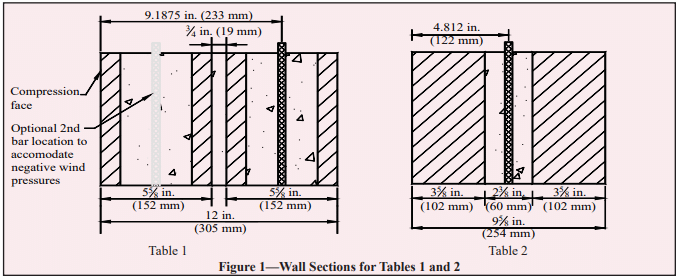
Unlike single wythe walls, where the geometric cross section is set by the product as manufactured, the cross section of a composite wall is determined by the combination of units and collar joint which can theoretically be any thickness. Practically speaking, code, structural and architectural requirements will narrow the options for wall sections. In addition to structural capacity, criteria specific to cross-section selection for reinforced composite walls include:
• location of reinforcement in collar joint or in unit cores;
• collar joint thickness;
• unit selection for each wythe.
Structural Reinforcement Location
The engineer has the option of locating the structural reinforcing steel in the collar joint or in one or both wythes. While there is no direct prohibition against placing reinforcement in both the collar joint and the unit cores, practically speaking there is rarely a structural reason to complicate the cross section with this configuration.
With some units, it may be easier to install reinforcement in the collar joint, such as when both wythes are solid or lack sufficient cell space for reinforcing bars. Depending on the units selected, the collar joint may or may not provide the option to center the reinforcement within the wall cross section. For example, when the units are not the same thickness, the collar joint does not necessarily span the center of the section.
Conversely, if off-set reinforcing is preferred, perhaps to accommodate unbalanced lateral loads, it may be benefi cial to place the vertical bars in the unit cores. Placing reinforcement in the unit cores permits a thinner collar joint and possibly a thinner overall cross-section. Unit cores may provide a larger and less congested opening for the reinforcing bars and grout since the collar joint will be crossed with connecting wall ties. There is also the possibly that for a given geometry, centered reinforcement does end up in a core space.
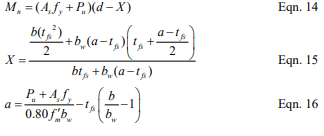
Reinforcement can also be placed in the cells of each wythe, providing a double curtain of steel to resist lateral loads from both directions, as in the case of wind pressure and suction.
Collar Joint Width
There are no prescriptive minimums or maximums explicit to collar joint thickness in either Building Code Requirements for Masonry Structures or the International Building Code, however there are some practical limitations for constructability and also code compliance in reinforcing and grouting that effect the collar joint dimension. Many of these are covered in TEK 16-01A but a few key points from the codes that are especially relevant for reinforced composite masonry walls included below:
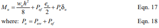
Wall tie length: Noncomposite cavity walls have a cavity thickness limit of 4½ in. (114 mm) unless a wall tie analysis is performed. There is no such limitation on width for filled collar joints in composite construction since the wall ties can be considered fully supported by the mortar or grout, thus eliminating concern about local buckling of the ties. Practically speaking, since cavity wall construction is much more prevalent, the availability of standard ties may dictate collar joint thickness maximums close to 4½ in. (114 mm).
Pour and lift height: Since the collar joint must be fi lled, the width of the joint infl uences the lift height. Narrow collar joints may lead to low lift or pour heights which could impact cost and construction schedule. See Table 1 in TEK 03-02A, Grouting Concrete Masonry Walls (ref. 5) for more detailed information.
Course or fine grout: Codes require a minimum clear distance of ¼-in. (6.3-mm) for fine grout and ½-in. (13-mm) for coarse grout between reinforcing bars and any face of the masonry unit.
Course or fine grout: Codes require a minimum clear distance of ¼-in. (6.3-mm) for fine grout and ½-in. (13-mm) for coarse grout between reinforcing bars and any face of the masonry unit.
Grout or mortar fill: Although codes permit collar joints to be filled with either mortar or grout, grout is preferred because it helps ensure complete filling of the collar joint without creating voids. Note that collar joints less than ¾ in. (19 mm), unless otherwise required, are to be filled with mortar as the wall is built. Increasing the slump of the mortar to achieve a solidly filled joint is preferred. This effectively requires a ¾-in. (19-mm) minimum on collar joints with structural reinforcing since it is also a code requirement that reinforcing bars be placed in grout, not mortar.
Reinforcing bar diameter: The reinforcing bar diameter cannot exceed one-half the least clear dimension of the collar joint.
Horizontal bond beams: Bond beams may be required to meet prescriptive code requirements such as seismic detailing. The collar joint then must be wide enough to accommodate the horizontal and vertical reinforcement along with the accompanying clearances for embedment in grout.
Unit Selection for Each Wythe
Aesthetic criteria may play a primary role in unit selection for reinforced composite walls. Designing the composite wall to match modular dimensions may make detailing of interfaces much easier. Window and door frames, foundations, connectors and other accessories may coordinate better if typical masonry wall thicknesses are maintained. Additional criteria that influence the selection of units for reinforced composite walls include:
Size and number of reinforcing bars to be used and the cell space required to accommodate them.
Cover requirements (see ref. 6) may come into play when reinforcement is placed in the cells off-center. Cover requirements could affect unit selection, based on the desired bar placement; face shell thickness and cell dimensions.
If double curtains of vertical reinforcement are used, it is preferable to use units of the same thickness to produce a symmetrical cross section.
Structural Considerations
Some structural considerations were addressed earlier in this TEK during the discussion of cross section determination. Since reinforced composite masonry by definition acts as one wall to resist loads, the design procedures are virtually the same as for all reinforced masonry walls. TEK 14-07C, ASD of Concrete Masonry (2012 IBC & 2011 MSJC) (ref. 7) details design procedures. A few key points should be stressed, however:
Analysis: Empirical design methods are not permitted to be used for reinforced multiwythe composite masonry walls.
Section properties: Section properties must be calculated using the transformed section method described in TEK 1601A (ref. 3).
Shear stresses: Shear stress in the plane of interface between wythes and collar joint is limited to 5 psi (34.5 kPa) for mortared collar joints and 10 psi (68.9 kPa) for grouted collar joints.
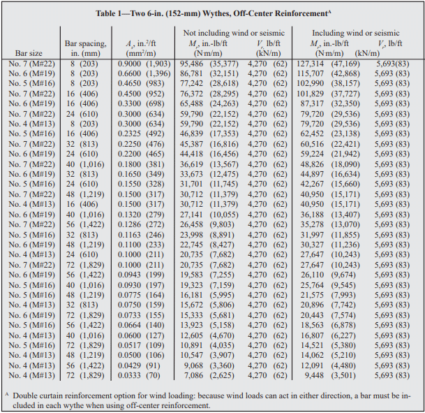
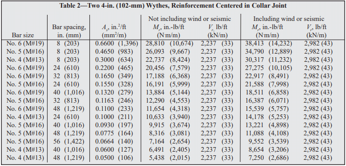
DESIGN TABLES
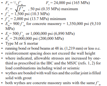
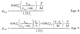
Design tables for select reinforced composite walls are included below. The tables include maximum bending moments and shear loads that can be sustained without exceeding the allowable stresses defined in the International Building Code and Building Code Requirements for Masonry Structures. These can be compared to Tables 1 and 2 of TEK 14-19B, ASD Tables for Reinforced CM Walls (2012 IBC & 2011 MSJC) (ref. 8) for wall subjected to uniform lateral loads to ensure the wall under consideration is not loaded beyond its design capacity. The examples are based on the following criteria:
The examples are based on the following criteria:
• Allowable stresses:
In addition to these tables, it is important to check all code requirements governing grout space dimensions and maximum reinforcement size to ensure that the selected reinforcing bar is not too large for the collar joint. The designer must also check shear stress at the unit/grout interface to ensure it does not exceed the code allowable stress for the design loading.
Table 2—Two 4-in. (102-mm) Wythes, Reinforcement Centered in Collar Joint
CONSTRUCTION AND DETAILING REQUIREMENTS
With composite wall construction, the two masonry wythes are not required to be built at the same time unless the collar joint is less than ¾ in. (19 mm), as the code mandates that those collar joints be mortared as the wall is built. Practically speaking it is easier to build both wythes at the same time to facilitate placing either the grout or the mortar in the collar joint at the code required pour heights.
It can be more complex to grout composite walls. Consider that a composite wall may have requirements to grout the collar joint for the full wall height and length but the cores of the concrete masonry units may only need to be partially grouted at reinforcing bar locations. Installing reinforcement and grout in the collar joint space can also be more time-consuming because of congestion due to the wall ties.
Nonmodular composite wall sections may cause diffi culty at points where they interface with modular elements such as window and door frames, bonding at corners and bonding with modular masonry walls.
NOTATIONS
As = effective cross-sectional area of reinforcement, in.²/ft (mm²/m) d = distance from extreme compression fiber to centroid of tension reinforcement, in. (mm) Eg = modulus of elasticity of grout, psi (MPa) Em = modulus of elasticity of masonry in compression, psi (MPa) Es = modulus of elasticity of steel, psi (MPa) Fb = allowable compressive stress due to flexure only, psi (MPa) Fs = allowable tensile or compressive stress in reinforcement, psi (MPa) Fv = allowable shear stress in masonry, psi (MPa) f’g = specified compressive strength of grout, psi (MPa) f’m = specified compressive strength of masonry, psi (MPa) Mr = resisting moment of wall, in.-lb/ft (kNm/m) Vr = resisting shear of wall, lb/ft (kN/m)
REFERENCES
International Building Code 2003. International Code Council, 2003.
Building Code Requirements for Masonry Structures, ACI 530-05/ASCE 5-05/TMS 402-05. Reported by the Masonry Standards Joint Committee, 2005.
This TECH describes a method of analysis and design for conventional and geosynthetic-reinforced segmental retaining walls (SRWs) under seismic loading. The methodology extends the approach for structures under static loading to simple structures that may be required to resist additional dynamic loads due to earthquakes. The seismic design method described briefly in this Tech Note, and in detail in the CMHA Design Manual for Segmental Retaining Walls and SRWallv4 design software (refs. 1, 2), adopts a pseudo-static approach and uses the Mononobe-Okabe (M-O) method to calculate dynamic earth forces. The methodology adopts many of the recommendations contained in AASHTO/FHWA (refs. 3, 4) guidelines for the design and analysis of mechanically stabilized earth (MSE) structures subjected to earthquake loads. However, the CMHA Design Manual for Segmental Retaining Walls goes beyond the AASHTO/FHWA publications by addressing the unique stability requirements of SRWs that are constructed with a dry-stacked column of modular block units.
Properly designed reinforced SRWs subjected to seismic and/or dynamic loading will in general perform well due to their flexible nature and enhanced ductility. When an SRW requires seismic analysis, that evaluation should be performed in addition to the static analysis to satisfy all static and seismic safety factors, as outlined in the Design Manual for Segmental Retaining Walls. The project’s geotechnical engineer should select the ground acceleration design parameters considering the local experience, state of practice and site conditions. CMHA’s methodology uses a displacement approach that explicitly incorporates wall movement in the stability analysis, assuming small outward displacements are allowed, and reduces the Peak Ground Acceleration (PGA) following FHWA’s approach. It should be noted that outward displacements caused by “near” maximum probable magnitude earthquakes may bring SRWs outside of tolerable batter deviations, thereby requiring mitigation. As with any other structure, the intent of the seismic design is to prevent catastrophic failure (a failure leading to risk to life, limb, or property), and needs to be evaluated after a near design event.
For satisfactory performance in the field, the designer should specify the best construction and inspection practices, adequately addressing items such as materials, installation, compaction, and internal and external drainage (i.e., drain tiles, chimney drains, swales, etc.). For more details refer to SRW-TEC-005-09, Guide to Segmental Retaining Walls (ref. 5), SRW-TEC-008-12, Inspection Guide for Segmental Retaining Walls (ref. 6), and the CMHA Design Manual for Segmental Retaining Walls.
DESIGN ASSUMPTIONS
The CMHA seismic design and analysis methodology applies when the following conditions are met:
SRW structures are free-standing and able to displace horizontally at the base and yield laterally through the height of the wall. This assumption is based on installation recommendations of a system that is placed on soils and a flexible leveling pad of well-compacted gravel or unreinforced weak concrete that can crack if necessary.
Reinforced and retained soils are cohesionless, unsaturated, and homogeneous. Soil strength is described by the Mohr-Coulomb failure criterion. The apparent cohesive strength component reported under Mohr-Coulomb failure criterion is ignored for conservatism. Adequate drainage details should also accompany the design to ensure the soils remain unsaturated and that the assumed design conditions are reached and maintained.
Vertical ground acceleration is zero (kv = 0). Vertical ground acceleration is ignored based on the presumption that horizontal and vertical accelerations associated with a seismic event do not coincide.
Geometry is limited to infinite or broken-backslope, and constant horizontal foreslope angle.
Live surcharges are ignored at the top of the soil surface behind the facing column given their transient nature.
Retained and reinforced soils are placed to a depth corresponding to the full height of the SRW facing units (i.e. wall design height, H).
Cap units are ignored in the stability analysis and assumed to be securely attached such that they cannot be dislodged during ground shaking.
The stabilizing influence of the wall embedment is ignored with the exception of bearing capacity analyses.
No permanent surcharge or footing load exists within the active failure wedge.
Global stability involving failure of soil volumes beyond the base of the SRW unit column and/or geosynthetic reinforced fill zone is not considered.
SRW structures are built on competent foundations for which excessive settlement, squeezing or liquefaction are not potential sources of instability.
If there are more complex conditions, or for cases where M-O formulation leads to unrealistic results, it is recommended that numerical procedures using the same principles of M-O formulation be used. These include the well-known graphical Culmann method, Coulomb’s trial wedge method, or limit equilibrium slope stability programs that are outside of the scope of the CMHA Design Manual.
A limitation of the pseudo-static seismic design method presented here is that it can only provide an estimate of the margins of safety against SRW collapse or component failure, and does not provide any direct estimate of anticipated wall deformations. This is a limitation common to all limit-equilibrium design methods in geotechnical engineering.
GEOSYNTHETIC REINFORCED SEGMENTAL RETAINING WALLS— MODES OF FAILURE
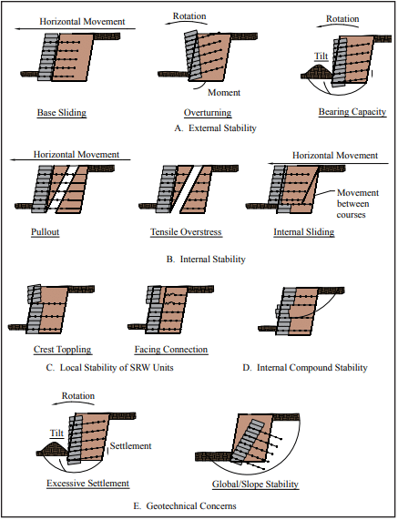
Stability analyses for geosynthetic reinforced SRW systems under static and seismic loading conditions involve separate calculations to establish factors of safety against external, internal, facing and internal compound modes of failure (Figure 1).
External stability calculations consider the reinforced soil zone and the facing column as a monolithic gravity structure. The evaluation of factors of safety against base sliding, overturning about the toe, and foundation bearing capacity is similar to that used for conventional reinforced concrete masonry gravity structures.
Internal stability analyses for geosynthetic reinforced soil walls are carried out to ensure that the structural integrity of the reinforced zone is preserved with respect to reinforcement over-stressing within the reinforced zone, pullout of geosynthetic reinforcement layers from the anchorage zone, and internal sliding along a reinforcement layer.
Facing stability analyses are carried out to ensure that the facing column is stable at all elevations and connections between the facing units and reinforcement layers are not over-stressed.
Internal compound stability analyzes the coherence of the block-geogrid system through potential compound slip circles that originate behind the soil-reinforced SRW and exit at the face of the wall.
Minimum recommended factors of safety (FS) of static and seismic design of geosynthetic reinforced SRW structures are given in Table 1. In general, FS for seismic design are taken as 75% of the values recommended for statically loaded structures following AASHTO/FHWA practice.
Potential concerns such as settlement of reinforced SRW structures due to compression, liquefaction, or squeezing of foundation soils is not considered here. Separate calculations for foundation-induced deformations may be required by the designer. In addition, slope instability involving volumes of soil beyond and below the base of the facing column is not considered. For global stability analysis, computer programs are available that consider the effects of both the stabilizing influence of reinforcement layers and destabilizing influence of seismic-induced ground acceleration (ref. 7).
Figure 1—SRW Failure Modes for Stability Analysis
Table 1—Recommended Minimum Factors of Safety and Design Criteria for Conventional/Reinforced SRWs
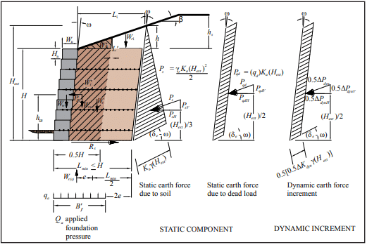
EXTERNAL STABILITY
External stability calculations are similar to those for conventional static conditions, with the addition of the inertial force due to wall weight and the dynamic earth increment. Dynamic earth pressure, shown in Figure 2, is used to calculate the destabilizing forces in otherwise conventional expressions for the factor of safety against sliding along the foundation surface, overturning about the toe, and bearing capacity failure of the foundations soils. By convention, only half of the dynamic earth force increment is applied when calculating external seismic forces on conventional and reinforced SRWs. The simplified geometry and forces shown in Figure 2 are used in external stability calculations.
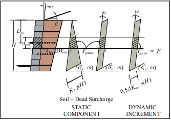
The contributory area approach (ref. 1, Sec. 7.5.2.2) used for the static stability analysis of SRWs is extended to the dynamic loading case (Figure 3). In this method, the reinforcement layers are modeled as tie-backs with the tensile force Fi in layer n equal to the earth pressure integrated over the contributory area Ac(n) at the back of the facing column plus the corresponding wall inertial force increment. Hence:
Fi(n) = khintΔWw(n) + Fgsta(n) + Fdyn(n)
where:
khintΔWw(n) = wall inertial force increment Fgsta(n) = static component of reinforcement load Fdyn(n) = dynamic component of reinforcement load.
Internal stability calculations are also similar to those carried out for conventional static conditions with the inclusion of dynamic earth pressure. For reinforced SRWs, full dynamic load is applied to internal stability with the exception of internal sliding that employs half ΔPdyn. Figure 3 shows the static and dynamic earth pressure distribution for internal stability calculations. The calculations for internal stability are presented in detail in Reference 1.
Figure 3—Geometry & Forces Used to Calculate Reinforcement Loads for Reinforced SRW Structures
FACING STABILITY
Facing stability calculations are similar to those used for the static analysis with the addition of the dynamic load. To evaluate the connection strength, the connection capacity at each reinforcement elevation is compared to the tensile force Fi already determined. The crest toppling is evaluated, determining the static, inertial and dynamic forces acting on the unreinforced top blocks. Only half of the dynamic load ΔPdyn is used to mirror the external overturning analysis.
INTERNAL COMPOUND STABILITY
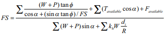
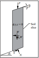
The consideration of seismic load for internal compound stability calculations is based on the addition of an inertial force (khW) associated with the mass of each soil slice (see Figure 4).
The incorporation of an additional dynamic load or inertial force is calculated as follows:
where:
di = vertical distance from the gravity center of the soil mass to the center of the slip surface R = radius of the slip surface Tavailable = available reinforcement force at the location of the intersection of the failure plane Favailable = available facing force at failure plane exit.
Figure 4—Soil Slice Showing Dynamic Load
FIELD PERFORMANCE
SRW performance during earthquakes is generally considered to be excellent (refs. 8, 9). Observations of SRWs within 31 miles (50 km) of the epicenter of both the Loma Prieta and Northridge earthquakes have shown that this type of retaining wall system can withstand considerable horizontal and vertical accelerations without experiencing unacceptable deformations. Similar to other structures subject to “near” maximum probable magnitude earthquakes, the designer should be aware that SRWs may need to be evaluated if damages are noticed, and repaired if necessary.
The design procedures presented in Design Manual for Segmental Retaining Walls, 3rd ed., provide a rational, detailed design methodology which, if followed, will allow designers to take advantage of SRW technology to build safe and economical retaining walls to withstand seismic forces.
Duncan, J.M., Low, B.K., and Shaeffer, V.R., STABGM: A Computer Program for Slope Stability Analysis of Reinforced Embankments, Virginia Polytechnic Institute,
Field Observations of Reinforced Soil Structures Under Seismic Loading, Collin, G., Chouery-Curtis, V.E., and Berg, R. R., Proceedings International Symposium on Earth Reinforcement Practice, Fukuoka, Japan, 1992.
Retaining Walls Stand Up to the Northridge Earthquake, Sandri, D., Geotechnical Fabrics Report 12 (4), 1994.
Segmental retaining walls (SRWs) function as gravity structures by relying on self-weight to resist the destabilizing forces due to retained soil (backfill) and surcharge loads. The self-weight of the SRW system is either the weight of the SRW units themselves including aggregate core fill if used (in the case of conventional SRWs) or the combined weight of the units, aggregate core fill if used and the reinforced soil mass (in the case of soil-reinforced SRWs).
Stability is provided by a coherent mass with sufficient width to prevent both sliding at the base and overturning about the toe of the structure under the action of lateral earth forces.
SRWs are durable and long lasting retaining wall systems. The typical size of SRW units, placed without mortar (dry- stacked), permits the construction of walls in locations with difficult access and allows the construction of tight curves or other complex architectural layouts. Segmental retaining walls are used in many applications, including landscaping walls, structural walls for changes in grade, bridge abutments, stream channelization, waterfront structures, tunnel access walls, wing walls and parking area support. This Tech Note provides a general overview of design considerations and the influences that height, soil, loads and geometry have on structural stability, based on Design Manual for Segmental Retaining Walls (ref. 1).
It is recommended that users of this Tech Note consult local building codes to determine additional SRW requirements and the engineering needs of their project. Where such specific requirements do not exist, CMHA recommends an engineered design performed by a registered professional on walls with a total (design) height, H, exceeding 4 ft (1.21 m) (for further detail, refer to SRW-TEC-008-12, Inspection Guide for Segmental Retaining Walls (ref. 3).
TYPES OF SEGMENTAL RETAINING WALLS
Conventional (Gravity) Segmental Retaining Walls
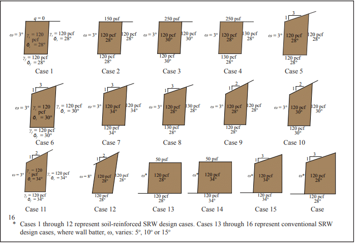
Conventional (gravity) SRWs retain soils solely through the self-weight of the SRW units. They can be constructed with either a single depth of unit or with multiple depths. The maximum wall height achievable using a conventional SRW is directly proportional to the unit’s weight, width, site geometry, surcharge load and retained soil type. Table 1 illustrates the effect of increasing the wall batter, unit width, unit’s in-place density (using either a solid unit or unit with aggregate core fill), and better quality backfill on the maximum height of a gravity wall.
Figure 1—Design Cases Corresponding to Table 1 and Figures 3 through 5
Soil-Reinforced Segmental Retaining Walls
Soil-reinforced SRWs are composite systems consisting of SRW units in combination with a mass of reinforced soil. The soil is stabilized by horizontal layers of reinforcement, typically a geosynthetic material. The reinforcement increases the effective width and weight of the gravity system.
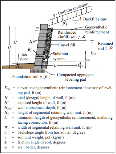
Geosynthetic reinforcement materials are high-tensile-strength polymeric materials. They may be geogrids or geotextiles, although current SRW construction typically uses geogrids. Figure 2 illustrates a typical soil-reinforced segmen- tal retaining wall and current design terminology.
The geosynthetic reinforcement is placed between the units and extended into the soil to create a composite gravity mass structure. This mechanically stabilized wall system, comprised of the SRW units and a reinforced soil mass, is designed to offer the required resistance to external forces associated with taller walls, surcharged structures, or more difficult soil conditions. Soil-reinforced SRWs may also be referred to as mechanically stabilized earth (MSE) walls, the generic term used to describe all forms of reinforced soil structures.
For soil-reinforced segmental retaining walls, geosynthetic reinforcement increases the mass of the composite SRW structure, and therefore increases its resistance to destabilizing forces. Geosynthetic length (L) is typically controlled by external stability or internal pullout capacity calculations. Increasing the length of the geosynthetic layers increases the SRW’s resistance to overturning, base sliding, bearing failure and geosynthetic pullout. In some cases, the length of the uppermost layer(s) is locally extended to provide adequate anchorage (pullout capacity) for the geosynthetic layers. The strength of the geosynthetic and the frictional interaction with the surrounding soil may also affect the geosynthetic length necessary to provide adequate pullout capacity. In addition, the required length to achieve minimum pullout capacity is affected by soil shear strength, backslope geometry and surcharge load (dead or live).
The minimum geosynthetic length required to satisfy external stability criteria is also a function of the soil shear strength and structure geometry (including wall batter, backslope, toe slope and surcharge). As the external driving force increases (as occurs with an increase in backslope angle, reduction in soil shear strength, or increase in external surcharge load (dead or live)), the length of the geosynthetic increases to satisfy minimum external stability requirements. Figures 3 through 5 illustrate the effect of backslope geometry, surcharge, soil unit weight and soil shear strength on the minimum required geosynthetic length to satisfy base sliding (FS = 1.5), overturning (FS = 1.5) and pullout (FS = 1.5). Regardless of the results of external stability analyses for sliding and overturning, the geogrid length (L) should not be less than 0.6H. The purpose of this empirical constraint is to prevent the construction of unusually narrow reinforced retaining walls. In addition, it is recommended that the absolute minimum value for L be 4 ft (1.2 m).
A sufficient number and strength of geosynthetic layers must be used to satisfy horizontal equilibrium with soil forces behind the wall and to maintain internal stability. In addition, the tension forces in the geosynthetic layers must be less than the design strength of the geosynthetic and within the allowable connection strength between the geosynthetic and the SRW unit. The optimum spacing of these layers is typically determined iteratively, usually with the aid of a computer program. Typically, the vertical spacing decreases with depth below the top of the wall because earth pressures increase linearly with depth.
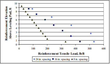
Vertical spacing between geosynthetic layers should be limited to prevent bulging of the wall face between geosynthetic connection points, to prevent exceeding the shear capacity between SRW units, to decrease the load in the soil reinforcement and at the geosynthetic-SRW unit connection interface. Figure 6 shows that smaller vertical reinforcement spacings reduce the geosynthetic reinforcement tensile load. Even when all internal and facial stability failure modes can be satisfied with larger spacings, however, a maximum vertical spacing between reinforcement layers of 24 in. (609 mm) is suggested to reduce construction stability issues. Note that some proprietary systems may be capable of supporting larger spacings: a 32 in. (813 mm) maximum spacing is suggested for these systems. This maximum spacing limits construction issues and also ensures that the reinforced soil mass behaves as a composite material, as intended by this design methodology. For SRW units less than or equal to 10 in. (254 mm) in depth, it is recommended that the maximum vertical spacing of the reinforcement layers be no more than twice the depth of the unit. For example, the maximum vertical spacing for a 9 in. (229 mm) deep modular block would be 18 in. (457 mm). Within these limits, the wall designer should choose an appropriate maximum reinforcement spacing for the proprietary system used.
Regardless of the reinforcement spacing, compaction of the reinforced fill zone is generally limited to 6 to 8 in. (152 to 203 mm) (compacted height) in order to achieve the necessary density and construction quality control. Compaction lift thickness in the retained zone is typically limited to the same height; however, thicker lifts can be accomplished if the specified density can be achieved throughout the entire lift thickness and it can be demonstrated that there are no adverse affects to the wall system performance or aesthetics. Regardless of the compaction method or equipment, the specified densities should be met and any variation from the approved specifications must be authorized by the SRW design engineer of the project.
Figure 3—Flat Slope Cases, Varying f, g and q—Cases 1, 2, 3 and 4
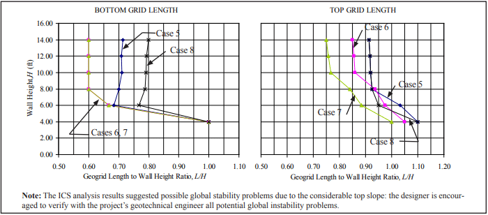
Figure 4—3:1 Top Slope Cases
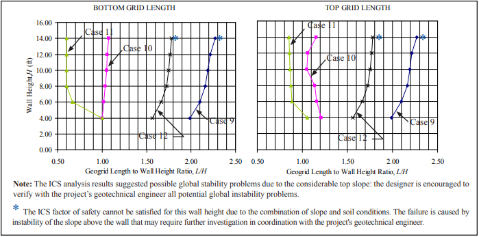
Figure 5—2:1 Top Slope Cases
Figure 6—Influence of Reinforcement Vertical Spacing on Calculated Reinforcement Tensile Load
Gravel Fill and Drainage Materials
Whenever possible, water should be directed away from SRWs. However, when water does reach an SRW, proper drainage components should be provided to avoid erosion, migration of fines, and hydrostatic pressure on the wall. Drainage features of the SRW will depend on site-specific groundwater conditions. The wall designer should provide adequate drainage features to collect and evacuate water that may potentially seep at the wall. The civil site engineer is typically responsible for the design of surface drainage structures above, below and behind the wall and the geotechnical engineer is typically responsible for foundation preparation and subsurface drainage beneath a wall. Reference 1 addresses in detail the drainage features and materials required for various ground water conditions on SRWs.
The gravel fill (formerly known as the drainage aggregate) and drain pipe shown on Figure 2 should only be relied on to remove incidental water—they are not meant to be the primary drainage path of the system. The gravel fill acts mainly as a compaction aid to reduce horizontal compaction stresses on the back of the SRW units during construction. It also prevents retained soils from washing through the face of the wall when designed as a soil filter, and facilitates drainage of incidental water, thereby relieving hydrostatic pressure or seepage forces.
The drain pipe collects and evacuates any water in the system through weep holes (maximum 50 ft (15.2 m) o.c. spacing) or directly to a drainage collection system. The elevation and diameter of the drain pipe should be determined by the wall designer depending on the specific site conditions.
The gravel fill should consist of at least 12 in. (305 mm) of a free-draining aggregate installed behind of the SRW units, and the drain pipe have a minimum diameter of 3 in. (75 mm).
Wall Batter
Segmental retaining walls are generally installed with a small horizontal setback between units, creating a wall batter into the retained soil (ω in Figure 2). The wall batter compensates for any slight lateral movement of the SRW face due to earth pressure and complements the aesthetic attributes of the SRW system. For conventional (gravity) SRWs, increasing the wall batter increases the wall system stability.
Unit Size and Shear Capacity
All SRW units provide a means of transferring lateral forces from one course to the next. Shear capacity provides lateral stability for the mortarless SRW system. SRW units can develop shear capacity by shear keys, leading lips, trailing lips, clips, pins or compacted columns of aggregate in open cores. In conventional (gravity) SRWs, the stability of the system depends primarily on the mass and shear capacity of the SRW units: increasing the SRW unit width or weight provides greater stability, larger frictional resistance, and larger resisting moments. In soil-reinforced SRWs, heavier and wider units may permit a greater vertical spacing between layers of geosynthetic, minimize the potential for bulging of the wall face. For design purposes, the unit weight of the SRW units includes the gravel fill in the cores if it is used.
Wall Embedment
Wall embedment is the depth of the wall face below grade (Hemb in Figure 2). The primary benefit of wall embedment is to ensure the SRW is not undermined by soil erosion in front of the wall. Increasing the depth of embedment also provides greater stability when site conditions include weak bearing capacity of underlying soils, steep slopes near the toe of the wall, potential scour at the toe (particularly in waterfront or submerged applications), seasonal soil volume changes or seismic loads.
The embedment depth is determined based on the wall height and toe slope conditions (see Table 2), although the absolute minimum suggested Hemb is 6 in. (152 mm).
Table 2—Minimum Wall Embedment Depth
Surcharge Loadings
Often, vertical surcharge loadings (q in Figure 2) are imposed behind the top of the wall in addition to load due to the retained earth. These surcharges add to the lateral pressure on the SRW structure and are classified as dead or live load surcharges.
Live load surcharges are considered to be transient loadings that may change in magnitude and may not be continuously present over the service life of the structure. In this design methodology, live load surcharges are considered to contribute to destabilizing forces only, with no contribution to stabilizing the structure against external or internal failure modes. Examples of live load surcharges are vehicular traffic and bulk material storage facilities.
Dead load surcharges, on the other hand, are considered to contribute to both destabilizing and stabilizing forces since they are usually of constant magnitude and are present for the life of the structure. The weight of a building or another retaining wall (above and set back from the top of the wall) are examples of dead load surcharges.
DESIGN RELATIONSHIPS
Table 1 summarizes the influence of increasing the wall batter, increasing the unit width, increasing the unit’s in-place density, and using better quality backfill on the maximum constructible height of a gravity SRW to satisfy sliding and overturning.
Figures 3 through 5 summarize the influences wall geometry, backslope and soil shear strength have on the minimum required reinforcement length to satisfy base sliding, overturning and pullout for a reinforced SRW.
These design relationships were generated using conservative, generic properties of SRW units. They are not a substitute for project-specific design, since differences between properties assumed in the tables and project-specific parameters can result in large differences in final design dimensions or factors of safety. Although wall heights up to 8 ft (2.44 m) for conventional (gravity) walls and 14 ft (4.28 m) for soil-reinforced walls are presented, properly engineered walls can exceed these heights.
For a detailed discussion of design and analysis parameters, the Design Manual for Segmental Retaining Walls (ref. 1) should be consulted. Design cases 1 through 16 are illustrated in Figure 1. All results shown were calculated using the software SRWall 4.0 (ref. 2) providing the appropriate geosynthetic lengths to satisfy sliding, overturning, and pullout (reinforced walls only) safety factors; or the maximum gravity wall height to satisfy sliding, overturning and internal shear. The final number, distribution and strength of the geogrids can only be determined by a designer for each specific SRW unit-geogrid combination to guarantee the appropriate safety factors for internal, facial stability and Internal Compound Stability (ICS) are met (for more detailed information, see Reference 1). The ICS can be met by reducing the geogrid spacing or increasing the grid length or strength: the examples presented here were calculated by reducing the geogrid spacing and maintaining the maximum and minimum geogrid lengths for convenience. See SRW-TEC-003-10, Segmental Retaining Wall Global Stability, (ref. 4) for more detailed information.
Large or commercial SRWs might also require foundation soil competency, settlement, and global stability analyses for a final design in coordination with other professionals in the project that are not addressed here (for more details on roles and responsibilities see SRW-TEC-002-10, Roles and Responsibilities on Segmental Retaining Wall Projects (ref. 5)). If the foundation and global analyses ultimately require a modification to the wall design, this must be done in coordination with the SRW designer.
EXAMPLE
A reinforced SRW is specified for a project that has the following characteristics:
H= 10 ft (3.0 m) Backslope 3:1 Live surcharge= 0 psf All soils Φ= 28° and γ = 120 pcf (1,922 kg/m³)
Determine the approximate geogrid lengths (L) at the bottom and top of the retaining wall.
Solution
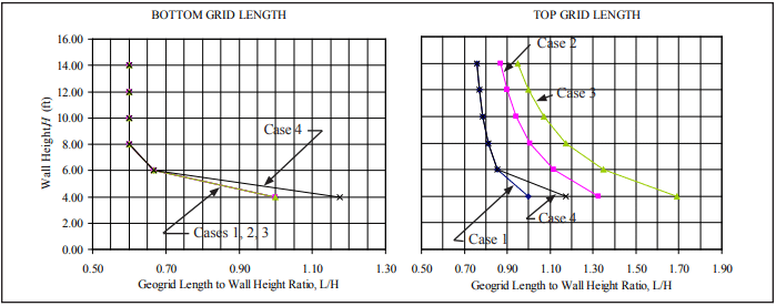
Determine the case that applies to this problem using Figure 1: Case 5 for this example. Using Figure 4 (3:1 backslope), find L/H for the given soil conditions and for the design height of 10 ft (3.0 m).
Bottom geogrid: L/H= 0.71; Lbottom = 0.71 x 10 ft = 7.1 ft (2.2 m) Top geogrid: L/H= 0.92; Ltop = 0.92 x 10 ft = 9.2 ft (2.8 m)
For estimating purposes, the volume of excavation and reinforced fill could be determined from the obtained data. The number, strength and distribution of the geogrids can only be determined by a designer for the specific SRW unit-geogrid combination to comply with the appropriate safety factors for internal, facial stability and ICS. The ICS is dependent on the spacing, length and strength of the geogrids: the designer is encouraged to perform the appropriate calculations to verify the distribution of the geosynthetics.
Masonry infill refers to masonry used to fill the opening in a structural frame, known as the bounding frame. The bounding frame of steel or reinforced concrete is comprised of the columns and upper and lower beams or slabs that surround the masonry infill and provide structural support. When properly designed, masonry infills provide an additional strong, ductile system for resisting lateral loads, in-plane and out-of-plane.
Concrete masonry infills can be designed and detailed to be part of the lateral force-resisting system (participating infills) or they can be designed and detailed to be structurally isolated from the lateral force-resisting system and resist only out-of-plane loads (non-participating infills).
Participating infills form a composite structural system with the bounding frame, increasing the strength and stiffness of the wall system and its resistance to earthquake and wind loads.
Non-participating infills are detailed with structural gaps between the infill and the bounding frame to prevent the unintended transfer of in-plane loads from the frame into the infill. Such gaps are later sealed for other code requirements such as weather protection, air infiltration, energy conservations, etc.
Construction of concrete masonry infilled frames is relatively simple. First, the bounding frame is constructed of either reinforced concrete or structural steel, then the masonry infill is constructed in the portal space. This construction sequence allows the roof or floor to be constructed prior to the masonry being laid, allowing for rapid construction of subsequent stories or application of roofing material.
The 2011 edition of Building Code Requirements for Masonry Structures (MSJC Code, ref. 1) includes a new mandatory language Appendix B for the design of masonry infills that can be either unreinforced or reinforced. Appendix B provides a straightforward method for the design and analysis of both participating and non-participating infills. Requirements were developed based on experimental research as well as field performance.
MASONRY INFILL LOAD RESPONSE
Several stages of in-plane loading response occur with a participating masonry infill system. Initially, the system acts as a monolithic cantilever wall whereby slight stress concentrations occur at the four corners, while the middle of the panel develops an approximately pure shear stress state. As loading continues, separation occurs at the interface of the masonry and the frame members at the off-diagonal corners. Once a gap is formed, the stresses at the tensile corners are relieved while those near the compressive corners are increased.
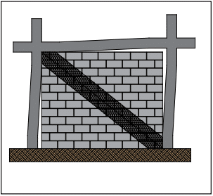
As loading continues, further separation between the masonry panel and the frame occurs, resulting in contact only near the loaded corners of the frame. This results in the composite system behaving as a braced frame, which leads to the concept of replacing the masonry infill with an equivalent diagonal strut, as shown in Figure 1. These conditions are addressed in the masonry standard.
Participating masonry infills resist out-of-plane loads by an arching mechanism. As out-of-plane loads increase beyond the elastic limit, flexural cracking occurs in the masonry panel. This cracking (similar to that which occurs in reinforced masonry) allows for arching action to resist the applied loads, provided the infill is constructed tight to the bounding frame and the infill is not too slender.
Figure 1—Concrete Masonry Infill as a Diagonal Strut
IN-PLANE SHEAR FOR PARTICIPATING INFILLS
For participating infills, the masonry is either mortared tight to the bounding frame so that the infill receives lateral loads immediately as the frame displaces, or the masonry is built with a gap such that the bounding frame deflects slightly before it bears upon the infill. If a gap exists between the infill and the frame, the infill is considered participating if the gap is less than ⅜ in. (9.5 mm) and the calculated displacements, according to MSJC Code Section B3.1.2.1. However, the infill can still be designed as a participating infill, provided the calculated strength and stiffness are reduced by half.
The maximum height-to-thickness ratio (h/t) of the participating infill is limited to 30 in order to maintain stability. The maximum thickness allowed is one-eighth of the infill height.
The MSJC Code requires participating infills to fully infill the bounding frame and have no openings—partial infills or infills with openings may not be considered as part of the lateral force resisting system because structures with partial infills have typically not performed well during seismic events. The partial infill attracts additional load to the column due to its increased stiffness; typically, this results in shear failure of the column.
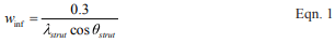
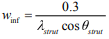
The in-plane design is based on a braced frame model, with the masonry infill serving as an equivalent strut. The width of the strut is determined from Equation 1 (see Figure 1).
where:
The term λstrut, developed by Stafford Smith and Carter (ref. 2) in the late 60s, is the characteristic stiffness parameter for the infill and provides a measure of the relative stiffness of the frame and the infill. Design forces in the equivalent strut are then calculated based on elastic shortening of the compression-only strut within the braced frame. The area of the strut used for that analysis is determined by multiplying the strut width from Equation 1 by the specified thickness of the infill.
The infill capacity can be limited by shear cracking, compression failure, and flexural cracking. Shear cracking can be characterized by cracking along the mortar joints (which includes st epped and horizontal cracks) and by diagonal tensile cracking. The compression failure mode consists of either crushing of the masonry in the loaded diagonal corners or failure of the equivalent diagonal strut. The diagonal strut is developed within the panel as a result of diagonal tensile cracking. Flexural cracking failure is rare because separation at the masonry-frame interface usually occurs first; then, the lateral force is resisted by the diagonal strut.
As discussed above, the nominal shear capacity is determined as the least of: the capacity infill corner crushing; the horizontal component of the force in the equivalent strut at a racking displacement of 1 in. (25 mm); or, the smallest nominal shear strength from MSJC Code Section 3.2.4, calculated along a bed joint. The displacement limit was found to be a better predictor of infill performance than a drift limit.
Generally, the infill strength is reached at lower displacements for stiff bounding columns, while more flexible columns result in the strength being controlled at the 1-in. (25-mm) displacement limit. While MSJC Code Section 3.2 is for unreinforced masonry, use of equations from that section does not necessarily imply that the infill material must be unreinforced. The equations used in MSJC Code Section 3.2 are more clearly related to failure along a bed joint and are therefore more appropriate than equations from MSJC Code Section 3.3 for reinforced masonry.
The equations used in the code are the result of comparing numerous analytical methods to experimental results. They are strength based. The experimental results used for comparison were a mixture of steel and reinforced concrete bounding frames with clay and concrete masonry. While some methods presented by various researchers are quite complex, the code equations are relatively simple.
OUT-OF-PLANE FLEXURE FOR PARTICIPATING INFILLS
The out-of-plane design of participating infills is based on arching of the infill within the frame. As out-of-plane forces are applied to the surface of the infill, a two-way arch develops, provided that the infill is constructed tight to the bounding frame. The code equation models this two-way arching action.
As previously mentioned, the maximum thickness allowed for calculation for the out-of-plane capacity is one-eighth of the infill height. Gaps between the bounding frame on either the sides or top of the infill reduce the arching mechanism to a one-way arch and are considered by the code equations. Bounding frame members that have different cross sectional properties are accounted for by averaging their properties for use in the code equations.
NON-PARTICIPATING INFILLS
Because non-participating infills support only out-of-plane loads, they must be detailed to prevent in-plane load transfer into the infill. For this reason, MSJC Code Section B.2.1 requires these infills to have isolation joints at the sides and the top of the infill. These isolation joints must be at least ⅜ in. (9.5 mm) and sized to accommodate the expected design displacements of the bounding frame, including inelastic deformation due to a seismic event, to prevent the infill from receiving in-plane loadings. The isolation joints may contain filler material as long as the compressibility of the material is taken into consideration when sizing the joint.
Mechanical connectors and the design of the infill itself ensure that non-participating infills support out-of-plane loads. Connectors are not allowed to transmit in-plane loads. The masonry infill may be designed to span vertically, horizontally, or both. The masonry design of the non-participating infill is carried out based on the applicable MSJC Code sections for reinforced or unreinforced masonry (Section 3.2 for unreinforced infill and Section 3.3 for reinforced infill using strength design methods). Note that there are seismic conditions which may require the use of reinforced masonry.
Because they support only out-of-plane loads, non-participating infills can be constructed with full panels, partial height panels, or panels with openings. The corresponding effects on the bounding frame must be included in the design.
BOUNDING FRAME FOR PARTICIPATING INFILLS
The MSJC Code provides guidance on the design loads applied to the bounding frame members; however, the actual member design is governed by the appropriate material code and is beyond the scope of the MSJC Code.
The presence of infill within the bounding frame places localized forces at the intersection of the frame members. MSJC Code Section B.3.5 helps the designer determine the appropriate augmented loads for designing the bounding frame members. Frame members in bays adjacent to an infill, but not in contact with the infill, should be designed for no less than the forces (shear, moment, and axial) from the equivalent strut frame analysis. In the event of infill failure, the loading requirement on adjacent frame members ensures adequacy in the frame design, thus preventing progressive collapse.
The shear and moment applied to the bounding column must be at least the results from the equivalent strut frame analysis multiplied by a factor of 1.1. The axial loads are not to be less than the results of that analysis. Additionally, the horizontal component of the force in the equivalent strut is added to the design shear for the bounding column.
Similarly, the shear and moment applied to the bounding beam or slab must be at least the results from the equivalent strut frame analysis multiplied by a factor of 1.1, and the axial loads are not to be less than the results of that analysis. The vertical component of the force in the equivalent strut is added to the design shear for the bounding beam or slab.
The bounding frame design should also take into consideration the volumetric changes in the masonry infill material that may occur over time due to normal temperature and moisture variations. Shrinkage of concrete masonry infill material may open gaps between the infill and the bounding frame that need to be addressed. Guidance for these volumetric changes is provided in MSJC Code Section 1.7.5.
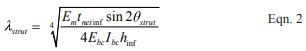
CONNECTORS
Mechanical connectors between the bounding frame and the infill provide out-of-plane support of the masonry, for both participating and non-participating infills. Connectors are required only for the direction of span (i.e., at the top and bottom of the infill for infill spanning vertically, for example). The connectors must be designed to support the expected out-of-plane loads and may not be spaced more than 4 ft (1.2 m) apart along the perimeter of the infill. Figure 2 shows an example of a mechanical connector composed of clip angles welded to the bottom flange of the steel beam.
Connectors for both participating and non-participating infills are not permitted to transfer in-plane loads from the bounding frame to the infill. For participating infills, in-plane loads are assumed to be resisted by a diagonal compression strut (see Figure 1), which does not rely upon mechanical connectors to transfer in-plane load. Research (ref. 3) has shown that when connectors transmit in-plane loads they create regions of localized stress and can cause premature damage to the infill. This damage then reduces the infill’s out-of-plane capacity because arching action is inhibited.
Figure 2—Example of Mechanical Infill Connector
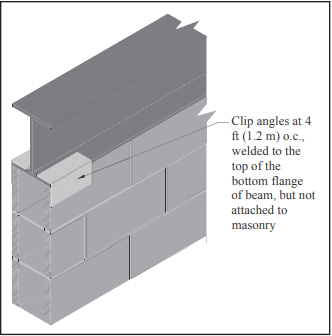
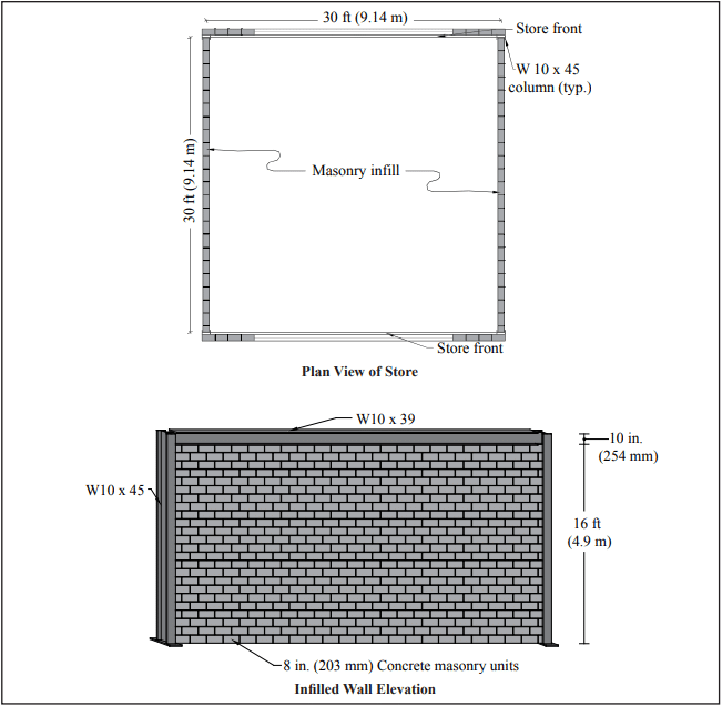
EXAMPLE 1: DESIGN OF PARTICIPATING MASONRY INFILL WALL FOR IN-PLANE LOADS
Consider the simple structure of Figure 3. The east and west side walls are concrete masonry infills laid in running bond, while the north and south walls are store-fronts typical of convenience stores. Steel frames support all gravity loads and the lateral load in the east-west direction. The bounding columns are W10x45s oriented with the strong axis in the east-west direction. The bounding beams above the masonry infill are W10x39s. The masonry infill resists the lateral load in the north-south direction.
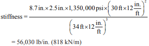
Use nominal 8-in. (203-mm) concrete masonry units, f’m = 1,500 psi (10.34 MPa), and Type S PCL mortar. Assume hollow units with face-shell bedding only. The total wall height measures 16 ft-10 in. (5.1 m) to the roof with the infill being 16 2 ft (4.9 m). The building is loaded with a wind load of 24 lb/ft² calculated per ASCE 7-10 (ref. 6) in the north-south direction. The roof acts as a one-way system, transmitting gravity loads to the north and south roof beams. Infill and bounding beam properties are summarized in Tables 1 and 2.
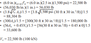
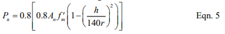
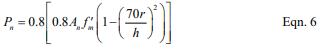
MSJC Code Section B.3.4.3 requires Vn inf to be the smallest of the following:
(6.0 in.)tnet inff’m
the calculated horizontal component of the force in the equivalent strut at a horizontal racking displacement of 1.0 in. (25 mm)
Vn/1.5, where Vn is the smallest nominal shear strength from MSJC Code Section 3.2.4, calculated along a bed joint.
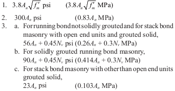
MSJC Code Section 3.2.4 requires the nominal shear strength not exceed the least of the following:
3.8 An √f ′m
300An
56An + 0.45Nv for running bond masonry not fully grouted and for masonry not laid in running bond, constructed of open end units, and fully grouted
90An + 0.45Nv for running bond masonry fully grouted
23An for masonry not laid in running bond, constructed of other than open end units, and fully grouted
Figure 3—Convenience Store Layout for Design Examples 1 & 2
Table 1—Infill Properties
Table 2—Bounding Frame Properties for In-Plane Loads
As a result of the wind loading, the reaction transmitted to the roof diaphragm is:
Reaction = ½ (24lb/ft²)(16.83 ft) = 202 lb/ft (2.95 kN/m)
Total roof reaction acting on one side of the roof is Reaction = (202 lb/ft)(30 ft) = 6,060 lb (27.0 kN)
This reaction is divided evenly between the two masonry infills, so the shear per infill is 3,030 lb (13.5 kN).
Using the conservative loading case of 0.9D + 1.0W, Vu = 1.0 Vunfactored = 1.0 (3,030 lb) = 3,030 lb (13.5 kN)
To be conservative, the axial load to the masonry infill is taken as zero.
To ensure practical conditions for stability, the ratio of the nominal vertical dimension to the nominal thickness is limited to 30 for participating infills. The ratio for this infill is: h/t = 192 in./8 in. = 24 < 30 The ratio is less than 30 and the infill is therefore acceptable as a participating infill.
The width of the equivalent strut is calculated by Equation 1 (MSJC Code Equation B-1):
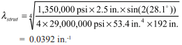
where λstrut is given by Equation 2 (Code Equation B-2).
The angle of the equivalent diagonal strut, θstrut, is the angle of the infill diagonal with respect to the horizontal. θstrut = tan-1 (hinf/linf) = tan-1 (192 in./360 in.) = 28.1°
Using Equation 2, the characteristic stiffness parameter, λstrut, for this infill is then:
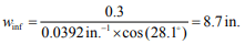
The resulting strut width is then:
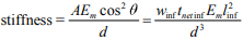
The stiffness of the equivalent braced frame is determined by a simple braced frame analysis where the stiffness is based on the elastic shortening of the diagonal strut. The strut area is taken as the width of the strut multiplied by the net thickness of the infill.
The stiffness is:
where d is the diagonal length of the infill, 34 ft (10.3 m) in this case.
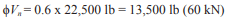
The nominal shear capacity, Vn, is then the least of:
The design shear capacity is:
The design shear capacity far exceeds the factored design shear of 3,030 lb (13.5 kN), so the infill is satisfactory for shear.
Additionally, the provisions of MSJC Code Section B.3.5 require that the designer consider the effects of the infill on the bounding frame. To ensure adequacy of the frame members and connections, the shear and moment results of the equivalent strut frame analysis are multiplied by a factor of 1.1. The column designs must include the horizontal component of the equivalent strut force, while the beam designs must include the verti cal component of the equivalent strut force. The axial forces from the equivalent strut frame analysis must also be considered in both the column and beam designs.
EXAMPLE 2: DESIGN OF PARTICIPATING MASONRY INFILL WALL FOR OUT-OF-PLANE LOADS
Design the infill from the previous example for an out-of-plane wind load W of 24 lb/ft² (1.2 kPa) per ASCE 7-10 acting on the east wall, using Type S PCL mortar, and units with a nominal thickness of 8 in. (203 mm). Assume hollow units with face-shell bedding only and that the infill is constructed tight to the bounding frame such that there are no gaps at the top or sides of the infill. See Table 3 for frame properties.
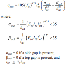
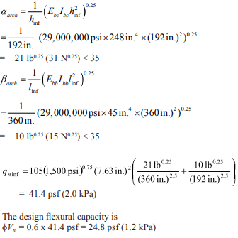
MSJC Code Section B.3.6 provides the equations for the nominal out-of-plane flexural capacity. MSJC Code Equation B-5 requires that the flexural capacity of the infill be:
Using the conservative loading case of 0.9D + 1.0W, the design wind load pressure is:
q = 1.0W = 1.0 x 24 psf = 24 psf (1.15 kPa) tinf = 7.625 in. < (⅛)(192 in.), OK
The design flexural capacity exceeds the factored design wind load pressure of 24 lb/ft² (1.2 kPa), so the infill is satisfactory for out-of-plane loading
Table 3—Bounding Frame Properties for Out-of Plane Loads
NOTATIONS
An = net cross-sectional area of a member, in.² (mm²) D = dead load, psf (Pa) d = diagonal length of the infill, in. (mm) Ebb = modulus of elasticity of bounding beams, psi (MPa) Ebc = modulus of elasticity of bounding columns, psi (MPa) Em = modulus of elasticity of masonry in compression, psi (MPa) f’m = specified compressive strength of masonry, psi (MPa) h = effective height of the infill, in. (mm) hinf = vertical dimension of infill, in. (mm) Ibb = moment of inertia of bounding beam for bending in the plane of the infill, in.4 (mm4) Ibc = moment of inertia of bounding column for bending in the plane of the infill, in.4 (mm4) linf = plan length of infill, in. (mm) Nv = compressive force acting normal to shear surface, lb (N) qn inf = nominal out-of-plane flexural capacity of infill per unit area, psf (Pa) t = nominal thickness of infill, in. (mm) tinf = specified thickness of infill, in. (mm) tnet inf = net thickness of infill, in. (mm) Vn = nominal shear strength, lb (N) Vn inf = nominal horizontal in-plane shear strength of infill, lb (N) Vu = factored shear force, lb (N) Vunfactored = unfactored shear force, lb (N) W = out of plane wind load, psf (Pa) winf = width of equivalent strut, in. (mm) αarch = horizontal arching parameter for infill, lb0.25 (N0.25) βarch = vertical arching parameter for infill, lb0.25 (N0.25) λstrut = characteristic stiffness parameter for infill, in.-1 (mm-1) θstrut = angle of infill diagonal with respect to the horizontal, degrees ϕ = strength reduction factor
REFERENCES
Building Code Requirements for Masonry Structures, TMS 402-11/ACI 530-11/ASCE 5-11. Reported by the Masonry Standards Joint Committee, 2011.
Stafford-Smith, B. and Carter, C. (1969) “A Method for the Analysis of Infilled Frames.” Proceedings of the Institution of Civil Engineers, 44, 31-48.
Dawe, J. L., and Seah, C. K. (1989a). “Behavior of Masonry Infilled Steel Frames.” Canadian Journal of Civil Engineering, Ottowa, 16, 865-876.
Tucker, Charles J. “Infilling the Frame With Masonry.” Structure, May 2012.
Tucker, Charles J. “Changing Masonry Standards: Masonry Infills.” Structure, Feb. 2012.
Minimum Design Loads for Buildings and Other Structures, ASCE SEI 7-10. American Society of Civil Engineers Structural Engineering Institute, 2010.
Building structural design requires a variety of structural loads to be accounted for: dead and live loads, those from wind, earthquake, lateral soil pressure, lateral fluid pressure as well as forces induced by temperature changes, creep, shrinkage and differential movements. Because any load can act simultaneously with another, the designer must consider how these various loads interact on the wall. For example, an axial load can offset tension due to lateral load, thereby increasing flexural capacity, and, if acting eccentrically, can also increase the moment on the wall. Building codes dictate which load combinations must be considered, and require that the structure be designed to resist the most severe load combination.
The design aids in this TEK cover combined axial compression or axial tension and flexure, as determined using the strength design provisions of Building Code Requirements for Masonry Structures (ref. 3). For concrete masonry walls, these design provisions are outlined in Strength Design of Concrete Masonry (ref. 1). Axial load-bending moment interaction diagrams account for the interaction between moment and axial load on the design capacity of a wall. This TEK shows the portion of the interaction diagram that applies to the majority of wall designs. Although negative moments are not shown, the figures may be used for these conditions, since with reinforcement in the center of the wall wall strength will be the same under either a positive or negative moment of the same magnitude. Conditions outside of this area may be determined using Concrete Masonry Wall Design Software or Concrete Masonry Design Tables (refs. 4, 5). The reader is referred to Loadbearing Concrete Masonry Wall Design (ref. 2) for a full discussion of interaction diagrams.
Figures 1 through 8 apply to fully or partially grouted reinforced concrete masonry walls with a specified compressive strength f’m of 1,500 psi (10.34 MPa), and a maximum wall height of 20 ft (6.10 m), Grade 60 (414 MPa) vertical reinforcement, with reinforcing bars positioned in the center of the wall and reinforcing bar spacing s from 8 in. to 120 in. ( 203 to 3,048 mm). Figures 1 through 8 apply to fully or partially grouted reinforced concrete masonry walls with a specified compressive strength, f’m, of 1500 psi (10.34 MPa), and a maximum wall height of 20 ft (6.09 m), Grade 60 vertical reinforcement, with reinforcing bars positioned in the center of the wall and reinforcing bar spacing, s, from 8 in. to 120 in. ( 203 to 3,048 mm). Each figure applies to one specific wall thickness and one reinforcing bar size. For walls less than 20 ft (6.1 m) high, figures 1 through 8 will be slightly conservative due to PΔ effects.
Figure 1, Figure 2
Figure 3& Figure 4
Figure 5, Figure 6
Figure 7, Figure 8
DESIGN EXAMPLE
An 8-in. (203-mm) thick, 20 ft (6.10 m) high reinforced simply supported concrete masonry wall (115 pcf (1,842 kg/m³)) is to be designed to resist wind load as well as eccentrically applied axial live and dead loads as depicted in Figure 9. The designer must determine the reinforcement size spaced at 24 in. (610 mm) required to resist the applied loads, listed below.
D = 520 lb/ft (7.6 kN/m), at e = 0.75 in. (19 mm) L = 250 lb/ft (3.6 kN/m), at e = 0.75 in. (19 mm) W = 20 psf (1.0 kPa)
The maximum moment due to the wind load is determined as follows.
The axial load used for design is the axial load at the location of maximum moment. This combination may not necessarily be the most critical section for combined axial load and flexure, but should be close to the critical location. The wall weight is estimated to be halfway between fully grouted and hollow (82 and 38.7 psf (400 and 189 kg/m2), respectively, for 115 pcf (1842 kg/m3) unit concrete density).
The eccentricity of the axial loads also induces bending in the wall and should be included in the applied moment. The magnitude of the moment due to the eccentric axial load must be found at the same location as the maximum moment.
During design, all load combinations should be checked, with the controlling load case used for design. For brevity, only the two combinations above will be evaluated here, since the axial load actually increases the flexural capacity for the first combination by offsetting tension in the wall due to the lateral load.
Figure 2 shows that No. 4 bars at 24 in. (M #13 at 610 mm) on center are adequate. If a larger bar spacing is desired, No. 5 at 32 in. (M #16 at 813 mm) or No. 6 at 48 in. (M #19 at 1219 mm) will also meet the design requirements. Although wall design is seldom governed by out-of-plane shear, the shear capacity should be checked. In addition, the axial load should be recalculated based on the actual wall weight (based on grout spacing chosen), then the resulting required capacity should be recalculated and plotted on the interaction diagram to check adequacy.
Figure 9 -Wall Section for Loadbearing Wall Design Example
NOMENCLATURE
D dead load, lb/ft (kN/m) e eccentricity of axial load – measured from centroid of wall, in. (mm) f’m specified masonry compressive strength, psi (MPa) h height of wall, in. (mm)
L live load, lb/ft (kN/m) Lr roof live load, lb/ft (kN/m)
Mu factored moment, in.-lb/ft or ft-lb/ft (kN⋅m/m) Pu factored axial load, lb/ft (kN/m)
s spacing of vertical reinforcement, in. (mm) W wind load, psf (kN/m²) y distance measured from top of wall, ft (m)
REFERENCES
Strength Design of Concrete Masonry, TEK 14-04B. Concrete Masonry & Hardscapes Association, 2002.
Concrete masonry elements can be designed using one of several methods in accordance with Building Code Requirements for Masonry Structures (ref. 1): empirical design, strength design or allowable stress design. This TEK provides a basic overview of design criteria and requirements for concrete masonry structures designed using the strength design provisions contained in Chapter 3 of the 2002 edition of Building Code Requirements for Masonry Structures (also referred to as the MSJC Code) (ref. 1) as referenced and modified in Section 2108 of the 2003 International Building Code (IBC) (ref. 2). In addition, changes to the strength design method incorporated into the 2005 edition of the MSJC Code (ref. 3) through Section 2108 of the 2006 International Building Code (ref. 4) are also reviewed, as are modifications included in the 2008 MSJC Code (ref. 5).
For empirical and allowable stress design requirements, the user is referred to TEK 14-08B, Empirical Design of Concrete Masonry Walls (ref. 6), and TEK 14-07C, ASD of Concrete Masonry (2012 IBC & 2011 MSJC) (ref. 7), respectively. Tables, charts, and additional design aids specific to the design of various concrete masonry elements can be found in other related TEK.
Strength design is based on the following design assumptions in conjunction with basic principles of engineering mechanics (refs. 1, 3, 5), as shown in Figure 1 for a reinforced element:
Plane sections before bending remain plane after bending. Therefore, strain in the masonry and in reinforcement, if present, is directly proportional to the distance from the neutral axis.
For unreinforced masonry, the flexural stresses in the masonry are assumed to be directly proportional to strain. For reinforced masonry, the tensile strength of the masonry is neglected when calculating flexural strength, but considered when calculating deflection.
The units, mortar, grout and reinforcement for reinforced masonry act compositely to resist applied loads.
The nominal strength of masonry cross-sections for combined flexure and axial load is based on applicable conditions of equilibrium.
The maximum masonry compressive stress is 0.80f’m for both reinforced and unreinforced masonry.
The maximum usable strain, εmu, at the extreme compression fiber of concrete masonry is 0.0025.
For reinforced masonry, compression and tension stresses in the reinforcement below the specified yield strength, fy, are taken equal to the modulus of elasticity of the reinforcement, Es, times the steel strain εs. For strains greater than the yield strain corresponding to fy, stress in the reinforcement is taken equal to fy.
For reinforced masonry, the compressive stress is rectangular and uniformly distributed over an equivalent compression zone, bounded by the compression face of the masonry with a depth of a = 0.80c.
Based on the prescribed design model outlined above, the internal distribution of stresses and strains is illustrated in Figure 1 for a reinforced masonry element. A more comprehensive review of the design model is provided in Masonry Structures, Behavior and Design (ref. 8).
Figure 1—Stress and Strain Distribution for Strength Design of Reinforced Masonry
2003 IBC STRENGTH DESIGN MODIFICATIONS
The 2003 IBC adopts the 2002 MSJC Code with two modifications specific to the strength design procedure in IBC Section 2108. The two modifications are as follows.
Section 2108.2 introduces a maximum effective compression width for out-of-plane bending of six times the nominal wall thickness, not to exceed the reinforcement spacing. This is similar to limits historically used by the allowable stress design provisions in the MSJC Code as well as those adopted into the 2005 MSJC Code for strength design, as reviewed below.
Welded and mechanical splices incorporated into masonry elements designed by the strength design method must also comply with Section 2108.3 of the 2003 IBC. For welded splices, the reinforcement to be welded must comply with ASTM A 706 (ref. 9). Splicing by mechanical connectors is classified as either Type 1 or Type 2 mechanical splices in accordance with ACI 318, Building Code Requirements for Structural Concrete (ref. 10). Type 1 mechanical splices are only required to develop 125 percent of the nominal yield strength of the reinforcement being spliced. Type 2 mechanical splices, conversely, must develop the full specified tensile strength of the reinforcement. Welded and Type 1 mechanical splices are not permitted to be used in the plastic hinge region of intermediate or special reinforced masonry shear walls.
2002 MSJC CODE STRENGTH DESIGN CRITERIA
Using strength design, the design strength of a masonry element is compared to the required (or factored) strength (indicated by the subscript u), which includes load factors to account for the uncertainty in predicting design loads and the probability of more than one design load acting simultaneously. The required strength is based on the strength design load combinations as required by Section 1605 of the IBC. At the option of the designer, or when the MSJC Code is used in conjunction with another building code that does not contain load combinations, masonry structures are designed to resist the load combination specified in ASCE 7, Minimum Design Loads for Buildings and Other Structures (ref. 11). For strength design, these load combinations are effectively the same.
The design strength of masonry is the nominal strength (indicated by the subscript n) multiplied by an appropriate strength reduction factor, Φ. The design is acceptable when the design strength equals or exceeds the factored strength (i.e., when ΦMn ≥ Mu) for all prescribed load combinations. The following sections cover the general strength design requirements applicable to both unreinforced and reinforced masonry assemblies, with the exception of design requirements for anchor bolts and lap splices. For these topics, the user is referred to TEK 12-03C, Design of Anchor Bolts Embedded in Concrete Masonry (ref. 12) and TEK 12-06A, Splices, Development and Standard Hooks for CM Based on the 2009 & 2012 IBC (ref. 13), respectively.
Strength Reduction Factors
To account for uncertainties in construction, material properties, calculated versus actual strengths and anticipated failure modes, the nominal strength of a masonry element is multiplied by an appropriate strength reduction factor, Φ. Strength reduction factors are used in conjunction with the load factors applied to the design loads. The values of the strength reduction factors for various types of loading conditions are:
for reinforced masonry elements subjected to flexure or axial loads; Φ = 0.90;
for unreinforced masonry elements subjected to flexure or axial loads; Φ = 0.60;
for masonry elements subjected to shear loads; Φ = 0.80;
for bearing on masonry elements; Φ = 0.60.
Drift and Deflection
When designing for earthquakes, the story drift (the relative displacement of adjacent stories) must be checked against the IBC prescribed allowable story drifts. When the MSJC Code is used in conjunction with a building code that does not contain allowable story drifts, the provisions of ASCE 7 are used. For masonry buildings with cantilevered shear walls, the IBC limits the story drift to 0.01hsx, where hsx is the height of the story below the level for which the drift is being calculated. For other types of masonry shear wall buildings, except masonry frames, the allowable story drift is limited to 0.007hsx. While the IBC includes story drift limits for masonry frame wall buildings, such structural configurations are rarely used. When calculating story drift, the calculated elastic deflection is multiplied by the deflection amplification factor, Cd, as prescribed in the IBC for the type of structural system being designed. The deflection amplification factor approximates the additional deflection due to inelastic response (if applicable) of the system during an earthquake. Due to the inherent in-plane stiffness of masonry assemblies, in-plane deflection and story drift are rarely a controlling limit unless a relatively large number of openings is incorporated that reduces the strength and stiffness along a line of lateral resistance.
Unlike allowable stress design, which permits deflections to be calculated assuming uncracked sections for both reinforced and unreinforced masonry, strength design requires that deflections of reinforced masonry elements be based on cracked section properties, which are limited to one-half of the gross section properties unless a rigorous cracked section analysis is performed. The deflection of unreinforced masonry elements, which are required to remain uncracked, use uncracked section properties.
Because unreinforced masonry elements must be designed to remain uncracked, deflection is rarely a controlling design limit for these systems. Reinforced masonry elements, however, particularly tall, slender walls bending in the out-of-plane direction, may exhibit excessive deflection even at relatively low applied loads. As such, the MSJC Code limits the mid-height deflection, δs, of reinforced masonry elements bending in the out-of-plane direction due to service level lateral and axial loads to 0.007h. Second order effects due to P-delta contributions must also be taken into account, which is usually accomplished through iteration until convergence is achieved.
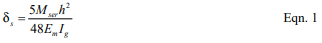
When the applied moment, Mser, is less than the moment required to cause cracking, Mcr, (Mser < Mcr) then the mid-height deflection of a masonry element subjected to a uniform out-of-plane load can be determined using Equation 1.
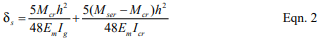
Conversely, when the applied moment, Mser, is greater than the moment required to cause cracking, Mcr, but less than the nominal moment strength of the assembly (Mcr < Mser < Mn) the mid-height deflection of a masonry element subjected to a uniform out-of-plane load can be determined using Equation 2.
The MSJC does not prescribe a method of determining the cracked moment of inertia, Icr. As such, any rational method of determining cracked section properties is permitted. CMUTEC-002-23, Weights and Section Properties of Concrete Masonry Assemblies (ref. 14), provides typical section properties for various uncracked wall sections. For use in Equations 1 and 2, the cracking moment can be taken as:
Where the modulus of rupture, fr, is obtained from Table 1 for the type of mortar and construction under consideration.
Material Properties
Due to the lack of available research data substantiating its use, the specified compressive strength of concrete masonry, f’m, designed by the strength design method is required to be at least 1,500 psi (10.34 MPa), but not larger than 4,000 psi (27.58 MPa). In addition, when used in a structural role, the specified compressive strength of grout is required to be at least equal to the specified compressive strength of concrete masonry, but not greater than 5,000 psi (34.47 MPa). For each of these upper limits on masonry assembly or grout compressive strength, the actual tested strength is permitted to exceed these values: the restriction applies only to specified strengths upon which the design is based. Note that these provisions are included in the 2005 MSJC Code as well.
Strength design of reinforced masonry is based on the specified yield strength of reinforcement, fy, which is limited to 60,000 psi (413.7 MPa). The actual yield strength of the reinforcement is limited to 1.3 times the specified yield strength. The combination of these requirements effectively precludes the use of bed joint reinforcement to be used as primary structural steel in masonry designed by the strength design method, because the nominal yield strength of bed joint reinforcement exceeds these limits. The compressive resistance of steel reinforcement is not permitted to be used unless lateral reinforcement is provided in compliance with Chapter 2 of the MSJC Code, except as permitted when checking the maximum reinforcement limits as described later.
Unreinforced Masonry
For unreinforced masonry, the masonry assembly (units, mortar and grout, if used) is designed to carry all applied stresses. The additional capacity from the inclusion of reinforcing steel, if present (such as reinforcement added to control shrinkage cracking or prescriptively required by the code), is neglected when designing unreinforced masonry elements. Because the masonry resists both tension and compression stresses resulting from applied loads, the masonry must be designed to remain uncracked.
Unreinforced Nominal Flexural Strength
The nominal flexural tensile strength of unreinforced concrete masonry is given by the modulus of rupture as prescribed in the MSJC Code, which varies with the direction of span, mortar type, bond pattern and percentage of grouting as shown in Table 1. These values apply to masonry subject to out-of-plane bending. For walls spanning horizontally between supports, the code conservatively assumes that stack bond masonry has no flexural bond strength across the mortared head joints, thus only the grout area (for horizontally grouted sections) is used. For this case, the modulus of rupture of the grout is taken equal to 250 psi (1720 kPa). Likewise, for masonry subjected to in-plane bending, the modulus of rupture normal and parallel to the bed joints is taken as 250 psi (1720 kPa).
For masonry elements subjected to a factored bending moment, Mu, and a compressive axial force, Pu, the resulting flexural bending stress is determined using Equation 4.
If the resulting value of Fu is positive, then the masonry section is controlled by tension and the modulus of rupture values of Table 1, reduced by the appropriate strength reduction factor (Φ = 0.60), must be satisfied. Conversely, if Fu as given by Equation 4 is negative, the masonry section is in compression and the design compressive stress of 0.80f’m applies. When using axial load to offset flexural bending stresses as described above, only dead loads or other permanent loads should be included in Pu.
Unreinforced Nominal Axial Strength
When unreinforced masonry walls are subjected to compressive axial loads only, the nominal axial compressive strength, Pn, is determined using equation 5 or 6, as appropriate. Unreinforced masonry is not permitted to carry net axial tension forces.
For elements with h/r not greater than 99:
For elements with h/r greater than 99:
Unreinforced Nominal Shear Strength
Shear stresses on unreinforced masonry elements are calculated using the net cross-sectional properties of the masonry in the direction of the applied shear force using:
Equation 7 is applicable to determining both in-plane and out-of-plane shear stresses. Because unreinforced masonry is designed to remain uncracked, it is not necessary to perform a cracked section analysis to determine the net section properties. In turn, the applied shear stresses (factored accordingly for the appropriate load combination) are compared to the nominal shear strength, Vn, of an unreinforced masonry section, which is the least of:
Table 1—Modulus of Rupture Values, psi (kPa)
Reinforced Masonry
The design of reinforced masonry in accordance with the MSJC Code neglects the tensile resistance provided by the masonry units, mortar and grout in determining the strength of the masonry assemblage. (The tensile strength of the units, mortar, and grout is considered, however, in determining the stiffness and deflection of a reinforced masonry element.) Thus, for design purposes, the portion of masonry subject to net tensile stress is assumed to have cracked, transferring all tensile forces to the reinforcement.
Using strength design, reinforcing bars used in masonry may not be larger than No. 9 (M #29) and bars may not be bundled. Further, the nominal bar diameter is not permitted to exceed one-eighth of the nominal member thickness or one-quarter of the least clear dimension of the cell, course or collar joint in which it is placed. The total area of reinforcing bars placed in a single cell or in a course of hollow unit construction may not exceed 4% of the cell area. Note that this limit does not apply at sections where lap splices occur. At lap splices, the maximum reinforcing bar area is increased to 8%, in both the 2002 and 2005 editions of the MSJC Code.
Maximum Flexural Reinforcement Ratio
To provide for a prescribed level of reinforced masonry ductility in the event of failure, the maximum reinforcement ratio, ρmax, is limited in accordance with Equation 8 or 9, as appropriate. Equation 8 applies to masonry cross sections that are fully grouted or where the neutral axis falls within the face shell of the masonry units in partially grouted construction. When the neutral axis falls within the cores of partially grouted construction, Equation 9 is used.
The tension reinforcement yield strain factor, α, varies with the seismic response modifi cation factor, R, masonry element, and type of loading as follows:
α = 1.3 for walls subjected to out-of-plane forces and designed using an R value greater than 1.5,
α = 5.0 for walls subjected to in-plane forces, for columns and for beams designed using an R > 1.5,
α = 2.0 for masonry structures designed using an R ≤ 1.5.
In the above set of requirements, R is larger for out-of-plane loads when R is less than or equal to 1.5, which is contrary to the underlying intent of providing increased ductility for systems and elements whose ductility demand may be relatively high. Several updates and revisions to the maximum have been incorporated into subsequent editions to the 2002 MSJC Code as reviewed below.
Reinforced Nominal Axial Strength
The nominal axial strength, Pu, of masonry walls, piers and columns, modified to account for the effects of slenderness, is determined using equation 10 or 11, as appropriate. The MSJC Code also limits the factored axial stress to 0.20f’m.
For elements with h/r not greater than 99:
For elements with h/r greater than 99:
Note that the reinforcing steel area, As, is included in the nominal axial strength calculation only if it is laterally confined in accordance with Chapter 2 of the MSJC Code.
Reinforced Nominal Flexural Strength
The nominal flexural strength, Mn, of a reinforced masonry element is determined as outlined below. In addition, the nominal flexural strength at any section along a member must be at least one-fourth of the maximum nominal flexural strength at the critical section.
When there are no axial loads, or when axial loads are conservatively neglected as may be appropriate in some cases, there are several circumstances to consider when determining the nominal flexural strength of reinforced masonry walls. For a fully grouted element, the internal moment arm between the resulting compressive and tensile forces is resolved to determine the resisting capacity of the section. Partially grouted walls are analyzed in the same way, but with the additional consideration of the possible influence of the ungrouted cores on the strength of the section. For partially grouted masonry bending out-of-plane, there are two types of behavior to consider.
In the first case, when the neutral axis (the location of zero stress) lies within the compression face shell, the wall is analyzed and designed using the procedures for a fully grouted wall.
In the second case, when the neutral axis lies within the core area, the portion of the ungrouted cells must be deducted from the area of masonry capable of carrying compression stresses.
The neutral axis location depends on the reinforcement spacing as well as the reinforcement ratio, ρ, and the distance between the reinforcement and the extreme compression fiber, d.
When analyzing partially grouted walls, it is typically initially assumed that the neutral axis lies within the compression face shell, as the analysis is more straightforward. The value of c is then calculated based on this assumption. If it is determined that the neutral axis lies outside the compression face shell, the more rigorous tee beam analysis is performed. Otherwise, the rectangular beam analysis is carried out.
Rectangular Beam Analysis
For fully grouted masonry elements and for partially grouted masonry walls with the neutral axis in the compression face shell, the nominal flexural strength, Mn, is calculated using equations 12 and 13 as follows:
Tee Beam Analysis
For partially grouted masonry walls where the neutral axis is located within the cores, the nominal flexural strength, Mn, is calculated using equations 14, 15, and 16 as follows:
To account for deflection resulting from out-of-plane loads and the additional bending moment due to eccentrically applied axial loads, the factored bending moment at the mid-height of a simply supported wall under uniform loading is required to be determined by Equation 17.
Multiple iterations may be necessary to determine the converging value of the resulting deflection.
Reinforced Nominal Shear Strength
Shear acting on reinforced masonry members is resisted by the masonry and shear reinforcement, if provided, in accordance with the following:
Where Vn may not exceed the values given by Equations 20 or 21, as appropriate.
Where M/Vdv is less than or equal to 0.25:
Where M/Vdv is greater than 1.00:
For values of M/Vdv between 0.25 and 1.00, the maximum value of Vn may be linearly interpolated.
The nominal shear strength provided by the masonry is determined in accordance with the following.
Where the value of M/Vdv need not be taken greater than 1.0.
When shear reinforcement is incorporated into reinforced masonry construction, the shear strength provided by the reinforcement is calculated in accordance with the following.
2006 IBC REQUIREMENTS
The following is a brief summary of the changes and modifications adopted into the 2005 MSJC Code as referenced in the 2006 IBC. The majority of the basic design provisions remain unchanged, with several notable exceptions as reviewed below.
2006 IBC Strength Design Modifications
The same modifications for welded and mechanical splices previously discussed in the 2003 IBC Strength Design Modifications section remain in the 2006 IBC. In addition, Section 2108 of the 2006 IBC has incorporated a limit of 72db on the maximum required length of lap splices used in masonry designed by the strength design method as determined by the 2005 MSJC lap splice provisions. While this limit is typically not triggered for relatively small bar diameters, it can reduce the required lap length of large diameter reinforcing bars or in cases where small cover distances are used. Refer to TEK 12-06A (ref. 13) for detailed splice length requirements.
Other changes to Section 2108 of the 2006 IBC reflect updates and modifications to the 2005 MSJC Code to remove redundant or conflicting requirements.
Due primarily to oversight, the 2002 MSJC Code did not include explicit provisions for determining the bearing strength of masonry subjected to concentrated loads. The bearing strength requirements adopted into the 2005 MSJC Code are similar to those used for allowable stress design, modified as necessary for use in strength design. The nominal bearing strength of masonry is taken as the greater of Equations 24 and 25:
The value of 0.6 in Equations 24 and 25 is a design coefficient, not the strength reduction factor, Φ, which also happens to be equal to 0.6 for determining the design bearing strength. For use in Equation 25, the following expression must also be satisfied:
Where A1 is the actual bearing area directly under the bearing plate and A2 is the effective bearing area, defined as a right o pyramid having A1 as a top plane and sloping at 45 . For walls laid in stack bond, the area defined by A2 is terminated at head joints unless a bond beam or other means of distributing stresses is used. The concentrated stresses are distributed over a length equal to the width of the bearing area plus four times the thickness of the supporting element, but not to exceed the center-to-center distance between the concentrated loads.
Modulus of Rupture
The 2005 MSJC Code incorporated a few modifications to the modulus of rupture values presented in Table 1 for flexural tension stresses normal to the bed joints of hollow, fully grouted assemblies, as shown in Table 2. These modifications recognize that the type of mortar has less of an influence on the modulus of rupture when the element is fully grouted.
In addition, instead of prescribing a single value of 250 psi (1.72 MPa) for masonry subjected to in-plane bending as in the 2002 MSJC Code, the 2005 MSJC Code requires the use of Table 1, as modified by Table 2, for all cases of in-plane and out-of-plane bending.
Table 2—Modifi cations to Modulus of Rupture Values in Table 1, as Included in the 2005 MSJC Code, psi (kPa)
Maximum Flexural Reinforcement Limits
The maximum flexural reinforcement requirements in the 2005 MSJC employ the same strain gradient approach as reviewed above, with several notable revisions.
Reinforcement is permitted to carry compression stresses, with or without lateral confining reinforcement. Further, the 1.25 factor on the nominal yield stress of the reinforcement as been removed. The resulting equations for the maximum flexural reinforcement limits are given by Equation 26 for fully grouted members or members subjected to in-plane loads, and Equation 27 for partially grouted masonry assemblies subjected to out-of-plane loads where the neutral axis falls in an open cell.
The tension reinforcement yield strain factor, α, is taken equal to the following values when Mu/Vudv ≥ 1.0 (indicating performance is dominated by flexure):
for intermediate reinforced masonry shear walls subjected to in-plane loads: α = 3.0,
for special reinforced masonry shear walls subjected to in-plane loads: α = 4.0,
for other masonry elements and loading conditions: α= 1.5.
For cases where Mu/Vudv ≤ 1.0 (indicating shear dominated performance) and R > 1.5: α = 1.5.
For masonry members where Mu/Vudv ≤ 1.0 and R ≤ 1.5, there is no limit on the amount of reinforcement permitted.
The axial load, P, for use in Equations 26 and 27, is the gravity axial load component determined from the following load combination: D + 0.75L + 0.525QE.
Effective Compression Width per Reinforcing Bar
Section 2108 of the 2003 IBC included limits on the effective compression width per reinforcing bar, which were subsequently removed from the 2006 IBC, as similar provisions were incorporated into the 2005 MSJC Code. For masonry construction in running bond, and for masonry in stack bond construction with bond beams space no further than 48 in. (1,219 mm) on center, the maximum width of the compression area used is limited to the least of:
the center-to-center spacing of the reinforcement;
six times the nominal thickness of the element; or
72 in. (1,829 mm).
Boundary Elements
New to the 2005 MSJC Code are design provisions for boundary elements incorporated into the end zones of masonry shear walls. Because the MSJC does not include minimum prescriptive reinforcement detailing requirements for boundary elements, it requires that when used, their performance be verified by testing. In addition, when meeting the requirements for geometrical symmetry, axial load and flexural performance, the MSJC Code permits the maximum reinforcement limits as reviewed above to be waived. This exception may or may not require the incorporation of special boundary elements, depending on the design circumstances.
2008 MSJC STRENGTH DESIGN REQUIREMENTS
At the time of publication, the 2008 edition of the MSJC Code had been finalized, but the 2009 edition of the IBC had not. In anticipation of the 2009 IBC adopting the 2008 MSJC by reference, following is a brief overview of changes to the strength design provisions of the 2008 MSJC Code. In addition to some reorganization, substantive revisions to the strength design method include:
The shear strength check to help preclude brittle failure of a masonry element during an earthquake was revised to apply only to special reinforced masonry shear walls. Previously, this check applied to both reinforced and unreinforced masonry elements regardless of seismic considerations.
The requirement to provide at least 80 percent of the lateral stiffness through shear walls was revised to apply only to Seismic Design Categories C and higher.
Instead of requiring that the deflection of all reinforced masonry elements be calculated on cracked section properties, the 2008 MSJC Code simply requires that the design “consider the effects of cracking and reinforcement on member stiffness,” thereby permitting more flexibility in design application.
A moment magnifier approach was incorporated for unreinforced masonry design in determining the influence of P-delta effects. The magnified moment, Mc, is determined either through a second-order analysis, or by the following:
For members with h/r ≤ 45, it is permitted to take δ = 1.0. For members with 45 < h/r ≤ 60, it is permitted to take δ = 1.0 provided that the maximum factored axial stress on the element does not exceed 0.72f’m.
NOTATIONS
An = net cross-sectional area of masonry, in.² (mm²) As = effective cross-sectional area of reinforcement, in.² (mm²) Av = cross-sectional area of shear reinforcement, in.² (mm²) A1 = bearing area under bearing plate, in.² (mm²) A2 = effective bearing area, in.² (mm²) a = depth of an equivalent compression zone at nominal strength, in. (mm) b = width of section, in. (mm) bw = for partially grouted walls, width of grouted cell plus each web thickness within the compression zone, in. (mm) C = resultant compressive force, lb (N) c = distance from the fiber of maximum compressive strain to the neutral axis, in. (mm) Cd = seismic deflection amplification factor Cn = nominal bearing strength, lb (N) D = dead load, lb (N) d = distance from the extreme compression fiber to centroid of tension reinforcement, in. (mm) db = nominal diameter of reinforcement, in. (mm) dv = actual depth of masonry in direction of shear considered, in. (mm) d’ = distance from the extreme tension fiber to centroid of compression reinforcement, in. (mm) Em = modulus of elasticity of masonry, psi (MPa) Es = modulus of elasticity of reinforcement, psi (MPa) eu = eccentricity of Puf in. (mm) Fu = net flexural bending stress due to factored loads, psi (MPa) Fvu = shear stress on unreinforced masonry elements, psi (MPa) f’m = specified compressive strength of masonry, psi (MPa) fr = modulus of rupture, psi (MPa) fy = specified yield strength of reinforcement, psi (MPa) h = effective height of masonry element, in. (mm) hsx = effective height of masonry element below level x, in. (mm) Icr = moment of inertia of cracked cross-sectional area of a member, in.4 (mm4) Ig = moment of inertia of gross cross-sectional area of a member, in.4 (mm4) In = moment of inertia of net cross-sectional area of a member, in.4 (mm4) L = live load, lb (N) M = unfactored maximum calculated bending moment at the section under consideration, in.-lb (N-mm) Mc = factored moment magnified for the effects of member curvature, in.-lb (N-mm) Mcr = cracking bending moment, in.-lb (N-mm) Mn = nominal moment strength, in.-lb (N-mm) Mser = applied bending moment, in.-lb (N-mm) Mu = factored moment, in.-lb (N-mm) Nv = compressive force acting normal to the shear surface, lb (N) P = unfactored axial load, lb (N) Pn = nominal axial strength, lb (N) Pu = factored axial load, lb (N) Puf = factored load from tributary floor or roof areas, lb (N) Puw = factored weight of wall area tributary to wall section under consideration, lb (N) QE = the effect of horizontal seismic forces, lb (N) Qn = first moment about the neutral axis of a section of that portion of the net cross section lying between the neutral axis and extreme fiber, in.³ (mm³) R = seismic response modification factor r = radius of gyration, in. (mm) Sn = section modulus of cross-section, in.³ (mm³) s = spacing of shear reinforcement, in. (mm) T = tension in reinforcement, lb (N) t = specified thickness of masonry element, in. (mm) tfs = concrete masonry face shell thickness, in. (mm) V = unfactored shear force, lb (N) Vm = shear strength provided by masonry, lb (N) Vn = nominal shear strength, lb (N) Vs = shear strength provided by shear reinforcement, lb (N) Vu = factored shear, lb (N) wu = out-of-plane factored uniformly distributed load, lb/in. (N/mm) X = for partially grouted masonry, distance from extreme compression fiber to centroid of the compression resultant, in. (mm) α = tension reinforcement yield strain factor δ = moment magnification factor δs = deflection due to service loads, in. (mm) δu = deflection due to factored loads, in. (mm) εmu = maximum usable compressive strain of masonry εs = steel strain εy = yield strain of reinforcement ρ = reinforcement ratio ρmax = maximum reinforcement ratio Φ = strength reduction factor
REFERENCES
Building Code Requirements for Masonry Structures, ACI 530-02/ASCE 5-02/TMS 402-02. Reported by the Masonry Standards Joint Committee, 2002.
2003 International Building Code. International Code Council, 2003.
Building Code Requirements for Masonry Structures, ACI 530-05/ASCE 5-05/TMS 402-05. Reported by the Masonry Standards Joint Committee, 2005.
2006 International Building Code. International Code Council, 2006.
Building Code Requirements for Masonry Structures, ACI 530-08/ASCE 5-08/TMS 402-08. Reported by the Masonry Standards Joint Committee, 2008.
Empirical Design of Concrete Masonry Walls, TEK 1408B, Concrete Masonry & Hardscapes Association, 2008.
ASD of Concrete Masonry (2012 IBC & 2011 MSJC), TEK 14-07C, Concrete Masonry & Hardscapes Association, 2004.
Drysdale, R. G., Hamid, A. A. and Baker L. R., Masonry Structures, Behavior and Design, Second Edition. The Masonry Society, 1999.
Standard Specification for Low-Alloy Steel Deformed and Plain Bars for Concrete Reinforcement, ASTM A 706/A 706M-01. ASTM International, 2001.
Building Code Requirements for Structural Concrete, ACI 318-02. American Concrete Institute, 2002.
Minimum Design Loads for Buildings and Other Structures, ASCE 7-02. Structural Engineering Institute of the American Society of Civil Engineers, 2002.
Design of Anchor Bolts Embedded in Concrete Masonry, TEK 12-03C. Concrete Masonry & Hardscapes Association, 2013.
Splices, Development and Standard Hooks for CM Based on the 2009 & 2012 IBC, TEK 12-06A, Concrete Masonry & Hardscapes Association, 2013.
Weights and Section Properties of Concrete Masonry Assemblies, CMU-TEC-002-23, Concrete Masonry & Hardscapes Association, 2023.
Compared to the typical forces usually included in building design, such as wind and seismic, there are many unique considerations involved in blast design. Except for high-threat scenarios associated with military and diplomatic facilities, a blast event is typically considered to be very unlikely but potentially catastrophic. The priority of blast design is to ensure the life safety of occupants and protection of critical assets, and therefore high levels of structural damage may be acceptable. To design a building to withstand any possible blast load event without significant damage tends to be prohibitively expensive, and achieving the balance between the additional costs of blast protection and the costs associated with significant but acceptable damage is often challenging.
For introductory purposes, the source of blast loading can be broadly categorized as either “intentional” or “accidental.” In today’s global political environment, “intentional” primarily refers to an act of terrorism that involves explosives. “Accidental” refers to the many other potential sources of blast loading such as explosions at industrial facilities, crashes of tractor trailers or trains that are transporting energetic materials, deflagration resulting from gas line leaks, etc. However, from a structural engineering standpoint, the design methodology is the same regardless of the source, although the source defines the design load.
Blast design associated with intentional load sources is one aspect of the broader subject of “security engineering.” In commonly used broad terms, security engineering involves detecting the possibility of intrusive behavior, deterring, delaying or denying a potential perpetrator from attacking, and defending people and assets against harm. Any scenario that involves design for an explosion attack will begin with identifying nonstructural approaches for protecting the subject building. For example, simply placing bollards around the building perimeter and restricting access to adjacent garages and parking areas can greatly reduce the blast design load by increasing the distance between the asset and a potential vehicle-borne explosive device, and thereby minimize construction costs. At the same time however, buildings such as embassies that must be constructed in urban settings, do not allow for a large standoff distance, and the only recourse is to design for the potentially intense blast loading. There are many consulting companies that specialize in site, architectural, and operational design and planning for security.
This TEK provides an introduction to the major concerns and challenges associated with design of concrete masonry walls for blast loading and directs the reader to sources for additional information and assistance.
TECHNICAL GUIDANCE, DOCTRINE & CRITERIA
Although blast design is not typically taught as part of college engineering curriculums, there are ample resources available for engineers to learn the basics of security engineering, explosion loading phenomena and blast design. This includes seminars and training courses taught by agencies such as the Federal Emergency Management Agency (FEMA) and the Interagency Security Committee (ISC), as well as through academic centers, companies and organizations around the United States. Standing technical committees such as the ASCE /SEI Committee on Blast, Shock and Impact and the ACI Committee 370 on Blast and Impact Load Effects, play prominent roles in disseminating state-of-the-art practice. There are also several international organizations, conferences, and technical publications focused on protection against blast and ballistic events, such as the International Association of Protective Structures (IAPS, protectivestructures.org), the International Journal of Protective Structures (multi-science.co.uk/ijps.htm), the International Conference on Protective Structures (ICPS), and the International Conference on Shock & Impact Loads on Structures (SILOS).
Several comprehensive reference books related to design for blast protection have emerged over the past several years. Most prominent are: Blast and Ballistic Loading of Structures (ref. 1), Modern Protective Structures (ref. 2) and Handbook for Blast Resistant Design of Buildings (ref. 3).
Some of the most frequently used design guides and criteria include:
Design of Blast-Resistant Buildings in Petrochemical Facilities (ref. 4)
Blast Protection of Buildings, ASCE/SEI 59-11 (ref. 5)
Structural Design for Physical Security: State of the Practice (ref. 6)
Blast Resistant Design Guide for Reinforced Concrete Structures (ref. 7)
FEMA-427: Primer for Design of Commercial Buildings to Mitigate Terrorist Attacks (2003)
FEMA-452: Risk Assessment: A How-To Guide to Mitigate Potential Terrorist Attacks (2005)
FEMA-426/BIPS-06: Reference Manual to Mitigate Potential Terrorist Attacks Against Buildings (2011)
Historically, many government departments and agencies, such as the Government Services Agency (GSA), Department of Defense (DoD), Department of State (DoS), and Department of Energy (DoE), developed and implemented their own independent criteria and standards. These independent standards compounded the complexity of designing and constructing government facilities. In fact, the Departments of the Army, Air Force, and Navy each had separate standards until the late 1990s. Fortunately however, much of this has been consolidated in recent years with the advent of Unified Facilities Criteria (UFC), Unified Facilities Guide Specifications (UFGS) and products of the Interagency Security Committee (ISC).
The UFC and UFGS documents are applicable to the design, construction, operation, maintenance, and modernization of all DoD facilities. The ISC Security Design Criteria was developed to ensure that security issues are addressed during the planning, design, and construction of all new federal courthouses, new federal office buildings, and major renovations, including leased facilities. Most of these criteria and guidelines are now disseminated in an easy-to-locate format provided by the National Institute of Building Sciences under the Whole Building Design Guide (wbdg.org). In addition, the U.S. Army Corps of Engineers Protective Design Center (PDC) provides information, criteria, and software for protective structures design and security engineering (pdc.usace.army.mil). Most DoD-sponsored research reports are available through the Defense Technical Information Center website (DTIC.mil). The distribution of some of these resources is restricted, but generally any U.S. company with the appropriate credentials can acquire the documents needed to conduct business for the U.S. Government by following instructions provided on the respective websites. Following are some of the most prevalent documents and tools relevant to blast design of masonry and other exterior wall components in government buildings and facilities.
Unified Facilities Criteria
UFC 3-340-01, Design and Analysis of Hardened Structures to Conventional Weapons Effects (For Official Use Only, FOUO)
UFC 3-340-02: Structures to Resist the Effects of Accidental Explosions
UFC 4-010-01: DoD Minimum Antiterrorism Standards for Buildings
UFC 4-010-02: DoD Minimum Antiterrorism Standoff Distances for Buildings (FOUO)
UFC 4-020-03FA/TM 5-853-3: Security Engineering: Final Design
UFC 4-023-03: Security Engineering: Design of Buildings to Resist Progressive Collapse
ISC, GSA, DoS
The Risk Management Process for Federal Facilities: An Interagency Security Committee Standard (ISC 2013)
Physical Security Criteria for Federal Facilities (ISC 2010)
Facilities Standards for the Public Buildings Service (GSA 2010) (superseded by ISC standards)
The Site Security Design Guide (GSA 2008) (superseded by ISC standards)
A&E Design Guidelines for U.S. Diplomatic Mission Buildings (DoS 2002)
PDC Software (includes user documentation)
BlastX: Internal and External Blast Effects Prediction —performs calculations of the shock wave and confined detonation products pressure and venting for explosions, either internal or external, to a structure.
CEDAW: Component Explosive Damage Assessment Workbook—a Microsoft Excel-based tool for generating pressure-impulse (P-i) and charge weight-standoff (CW-S) damage level curves for structural components.
ConWep: Conventional Weapons Effects—a collection of conventional weapons effects analysis tools that perform a variety of conventional weapons effects calculations including airblast loads, fragment and projectile penetrations, breach, cratering, and ground shock.
PSADS: Protective Structures Automated Design System —automates the procedures in UFC 3-340-01 into digitally read graphical tools.
SBEDS: Single-Degree-of-Freedom Blast Effects Design Spreadsheets—Excel-based tool for designing structural components subjected to dynamic loads using single degree of freedom (SDOF) methodology.
RECENT RESEARCH & DEVELOPMENT ON MASONRY PERFORMANCE UNDER BLAST LOADS
From a blast-response standpoint, unreinforced masonry behaves much differently from reinforced masonry. Unreinforced masonry tends to be very brittle under blast loads, and has been demonstrated to fail catastrophically at relatively low load intensity. Fragmentation of brittle exterior wall components, namely unreinforced masonry and windows (glass), is the primary cause of injury and death when an occupied building is subjected to an external explosion. For this reason, the U.S. Department of Defense (UFC 4-010-01) and the ASCE blast standard (ref. 5) prohibit the use of unreinforced masonry in the construction of new buildings that must be designed to withstand significant blast demands.
Due to the fragmentation susceptibility combined with the widespread use of unreinforced masonry throughout the world, there has been extensive research supported by many agencies in the U.S. and abroad on the use of a variety of materials such as fiber composite laminates, geotextiles, shotcrete with wire meshing and spray-on polymers for retrofitting existing unreinforced masonry for blast protection. Design guidelines and commercially available products have evolved, some of which are included in the documents referenced above, and research on the subject of retrofitting existing unreinforced masonry has recently subsided.
In contrast, because of the ductility provided by the reinforcement and the mass provided by the grout, even minimally reinforced fully grouted masonry provides a high level of blast resistance. The distinction between unreinforced masonry and reinforced masonry is very important because properly designed and detailed reinforced masonry can provide a high level of protection at relatively low cost. Potentially misleading broad statements such as “masonry is considered a very brittle material that may generate highly hazardous flying debris in the event of an explosion and is generally discouraged for new construction” (FEMA-426/ BIPS-06 2011) are intended to reference unreinforced masonry.
Recent full-scale blast testing conducted by the Air Force Research Laboratory (AFRL) (refs. 8, 9) on fully grouted 8-in. (203-mm) concrete masonry walls with No. 5 vertical reinforcement at 40 in. (M #16 at 1,016 mm) on center (one bar at the cell center) and W1.7 (9 gage, MW11) horizontal joint reinforcement 16 in. (406 mm) on center demonstrated excellent ductility under blast loading (Figure 1). That testing involved panels with and without clay brick veneer and polystyrene foam insulation (typical cavity wall construction). The veneer enhances resistance due to the added mass, but does not significantly increase the section moment of inertia through composite action. Furthermore, it was noted that the veneer ties provide sufficient strength and stiffness to transfer the forces from the reflected pressure from the veneer exterior to the structural wythe without significantly loading the insulation.
The second phase of the AFRL masonry test program demonstrated that the ungrouted cells of partially grouted exterior walls tend to breach and turn into hazardous fragments similar to unreinforced masonry, and therefore partially grouted walls should not be used when designing against a significant blast demand (refs. 10, 11) (see Figure 2).
Figure 1—Result of Full-Scale Explosion Testing of Fully Grouted CMU and Cavity Walls
Figure 2—Result of Full-Scale Explosion Testing of Partially Grouted CMU Demonstrating Breaching Tendency
BLAST PHENOMENA AND DESIGN LOAD
The intensity of blast loading on a given structure depends upon several key factors, such as the type of energetic material, distance between load origin and the structure, position of the load origin relative to the ground, the relative orientation of the structure, etc. Explosions external to a building tend to result in a single predominate reflected pressure pulse that is relatively easy to predict. The duration of loading on a building façade from external explosions is typically characterized in milliseconds (seconds/1,000). Forces resulting from internal explosion are significantly more complex to predict due to reflections and gas pressure venting. The duration of the reflection peaks resulting from internal detonations may be only a few microseconds, followed by a longer build-up and release of gas pressure through venting mechanisms.
The most intense loading occurs on forward-facing components closest to the blast origin (reflected pressure), but an explosion that is external to a building can also cause significant side, rear, and roof loadings. Figures 3 and 4 illustrate some of the basic factors involved in explosion loading on structures and the idealized shape of pressure over time. For purposes of exterior wall system structural design, the negative phase is typically (and conservatively) ignored, and the positive impulse is simplified to a right triangle form (Figure 5). Load is defined in terms of anticipated size (i.e., industrial container size, truck-, car- or person-carried explosive device, etc.) and distance between the building component being designed and blast origin (commonly referred to as the “standoff distance”). A close-in blast tends to cause local breaching; far-away blasts tend to result in a flexural response of exterior wall components. The intensity degrades exponentially with distance between subject component and blast origin; therefore one of the primary protection methods is always to maximize the standoff distance. It should be understood that the size of explosive device is not a singular descriptor of the potential level of damage/harm that could be caused—a well-placed satchel device can be more destructive than a truck full of explosives detonated on the street.
Many of the resources listed above describe the blast load phenomena in great detail. Approximate methods for transforming explosive type, size and distance into the peak pressure and impulse required for engineering analysis and design are thoroughly defined in UFC 3-340-02 (ref. 12). Airblast calculators such as CONWEP are also available, and some engineering analysis software such as SBEDS, WAC, and LS-DYNA include embedded blast load calculators. Accurate analysis of internal detonations or explosions that may involve multiple reflections requires advanced shock analysis and computational physics codes.
Some government provided documentation and software used for blast load prediction is restricted as “for official use only” (FOUO), but general airblast load methodology and calculators are not sensitive and can be openly distributed. Restriction occurs when the documentation or software contains specific military-use or mission-specific information or capabilities. Therefore, some documentation such as UFC 3-340-01 and calculators such as CONWEP are restricted since they contain weapons effects information. However, any contractor or organization with the proper need and contract credentials can gain access to the necessary information and tools.
Figure 5—Simplified Right Triangular Blast Pressure Idealization for Blast Load (ref. 12)
DESIGN FOR FAR-FIELD BLAST LOADS
Once the design load has been defined, the structural engineer can proceed with the dynamic response calculations required to analyze the masonry component. In general, blast analyses for designing exterior wall systems are done in the latter phases of design. The components are typically first designed for gravity, wind and seismic loads, and then the design is checked for blast adequacy and altered for blast resistance if needed.
Single-degree-of-freedom (SDOF) response calculations are most common, but some blast design engineers prefer more robust, but more complicated and expensive, finite element analyses. Finite element modeling can provide a more accurate and detailed response simulation, but must only be used by persons with a high degree of knowledge in finite element theory and application.
Response Limits
Component deflection is the first focus of the dynamic analyses for systems that will respond in a flexural mode. The required level of protection (LOP) for individual structural components must be defined during the planning process. Table 1 introduces the damage categorization language typically used. Components are generally categorized as primary, secondary or non-structural, as described in Table 2. Table 3 illustrates the typical terminology used to describe component damage. And, Table 4 is used to relate LOP to component damage. The process and information presented in Tables 1 through 4 may differ slightly between the various standards and criteria, but the overall approach and concepts involved will be essentially the same.
Blast criteria for flexural components are typically written in terms of the allowed ductility (μ) and rotation (θ). As part of the process, the building is categorized according to the level of damage that is acceptable, and then the rotation limit is set according to that level of acceptable damage. “Ductility” is the ratio of the maximum deflection of the component to the yield deflection of the component; “rotation” is defined in Figure 6. The limits for masonry are defined in Table 5.
Table 1—Structural Damage Associated with Building Levels of Protection (ref. 13)
As mentioned above, single degree of freedom analysis is generally considered to be the standard approach for blast design of flexural components such as masonry walls used for exterior wall systems. Pressure-impulse (P-I) diagrams, also called iso-damage curves, such as those provided through the CEDAW software, can be used for preliminary design or rapid assessment of structural components (ref. 14). The fundamentals of SDOF analysis are defined in commonly-used structural dynamics textbooks such as Biggs, Chopra, and Tedesco et al. (refs. 15, 16, 17), as well as in many of the references discussed above, and the reader must review those sources to fully understand the methodology.
SDOF analysis is not unique to blast analysis of structures; it is a common technique for dynamic analysis of a wide range of structural and mechanical systems. However, some aspects of the resistance definition approach are specific to blast load analyses. The following provides a brief overview of the methodology.
In SDOF blast design, the component, such as a masonry wall, is idealized as a beam subjected to the transient blast load, which is then reduced to the transverse motion of a single point (degree-of-freedom) (Figure 7). Equation 1 is solved numerically for transient displacements up to the peak displacement. The system is therefore comprised of a nonlinear resistance function (translated through time increments into stiffness), a transient pressure loading, and an effective mass. Once the displacement is solved, the peak rotation and other design parameters can then be related to the maximum displacement. The approach can include damping, but damping is typically not important for calculating the first peak displacement of flexural systems subjected to impulse loading.
The resistance function used for reinforced masonry is essentially the same as used for reinforced concrete. The resistance is idealized as an elasto-plastic form for simple (determinate) support conditions, or multi-linear for other support conditions, as illustrated in Figure 8. The ultimate resistance (ru) is defined using resistance definitions provided in standards and engineering guidelines such as Section 6-8: Design Criteria for Reinforced Masonry Walls of UFC 3-340-02 (ref. 12) and Chapter 7—Masonry Components of the SBEDS methodology manual (ref. 18). In addition to the usual material properties, dimensions, etc., that play into concrete static design resistance, the approach used to define the blast resistance also includes factors that compensate for effects of strain rate on material properties. Although strain rate effects are localized and vary spatially and temporally, the approach used in typical SDOF-based blast design is to smear the effect using single dynamic increase factors (DIF) that are applied to the material strengths (i.e., concrete and steel) used in the resistance definition. The dynamic increase factors for masonry are 1.19 for flexure, 1.12 for compression, and 1.10 for direct shear, which are the same as used for concrete (ref. 5). A DIF on yield of approximately 1.17 is also typically applied to Grades 40 and 60 reinforcing steel.
Unreinforced masonry does not exhibit any significant resistance at deflections larger than the yield deflection. Therefore, a brittle flexural response is assumed based on the moment capacity controlled by the flexural tensile strength between masonry units. Increase in resistance due to compression arching, which may be significant, can be considered if the supports are sufficiently rigid and there are no gaps between the wall boundaries and supports. There is no available test data on the dynamic flexural tensile strength of masonry walls, therefore a value of 1.38 MPa (200 psi) is recommended, based on use of this assumed value in SDOF analyses that approximately matched measured unreinforced masonry wall response from a number of explosive and shock tube tests (refs. 13, 14).
The SDOF methodology for nonloadbearing wall components can be easily programmed. However, the axial force effects in loadbearing components xe significantly xm complicate the procedure. The axial load changes the system’s resistance, and P-Δ effects amplify the displacement. Therefore, to incorporate these effects into a SDOF framework, either both (effect of axial load on resistance and P-Δ effects) must be incorporated into the resistance definition, or only the effect of axial load on resistance changes the resistance and P-Δ effects are incorporated through each time step. SDOF calculators such as SBEDS and Wall Analysis Code (ref. 19) developed specifically for blast analysis of wall components are available, some of which include the ability to analyze loadbearing components.
Figure 7—Equivalent Spring-Mass SDOF System
Figure 8—Elasto-Plastic Resistance Curve Assumed for Flexural Response
Maximum Shear and Reaction Forces
Shear failure in masonry can occur before the full flexural response mode occurs and can be in the form of diagonal shear or direct shear, as illustrated in Figure 9 (ref. 3). From an SDOF calculation perspective, the reaction force transferred to the connection and the maximum flexural shear force are the same at any point in analysis time. In reality though, the transient force demand on a connection is a function of the connection rigidity, which is not considered in the typical SDOF methodology. For blast design purposes, this demand can be estimated using two approaches:
as an equivalent static reaction force based upon the flexural capacity of the member, and
as the maximum of a transient dynamic shear force calculated using SDOF methodology.
The equivalent static reaction force simply comes from balancing the maximum flexural resistance provided by the component, including any strain rate effects (or DIF), with the end or edge support reactions; it therefore does not require calculations involving the equation of motion. This force can be used to check the shear capacity of components and to design the connections. Therefore, it is also referred to as equivalent support shear or equivalent static shear load. Connections are typically designed to have an ultimate capacity that will exceed the equivalent static reaction force. Connections typically have significantly less ductility than the connected components and therefore the ultimate strength of the component should not be controlled by the connections. ASCE/SEI 59-11 also requires that “the design shear forces shall not be less than the shear forces associated with the nominal flexural strength of the element.”
The dynamic reaction force is evaluated from dynamic force equilibrium through time steps. It is a function of the component resistance, inertial effects, and the applied load at each time step. Since high intensity, very short duration fluctuations will occur in the first milliseconds of dynamic reaction force histories, dynamic reaction forces are not usually used to define the maximum shear demand in a component or to design connections. The assumption that the acceleration distribution, and therefore the inertia force distribution, along the span is the same as the deflected shape assumed in the SDOF approach and does not vary with time is not accurate. The deflected shape of blast-loaded flexural components is flatter than the static deflected shape very early in response time, with almost all curvature occurring very close to the supports. At later times, when significant deflections occur, the shape changes to more closely approximate the first mode, or static flexural response shape that is typically assumed in SDOF analyses. For these reasons, among others, the dynamic reaction calculated from standard SDOF methodology is typically not considered to be accurate during very early time response, and the equivalent static reaction force is typically preferred.
Figure 9—Shear Response Modes for Masonry
Detailing
Proper detailing is critical to achieving the desired ductile failure modes that formed the bases of design and to maximizing the protection capacity of the component. Reinforced concrete masonry components must allow for the full development of reinforcing steel. Longitudinal reinforcement can be placed in several common configurations, as illustrated in Figure 10. The spacing between vertical bars is determined through the standard TMS 402 (ref. 20) design approach that meets the LOP requirements for the building being designed. All cells must be grouted for LOP III and LOP IV. Vertical bars should be placed on each side of control joints. Splices must be tension lap splices for LOP III and LOP IV. Mechanical and weld splices should be limited to regions that will remain elastic under loading and should meet TMS 402 specifications. Reinforced bond beams must be placed at the top of the wall and at all floor diaphragms. Lintels need to be reinforced as well. All horizontal discontinuous reinforcement should be hooked according to TMS 402 for special shear walls – see Figure 10.
Figure 10—Examples of Masonry Reinforcement Configurations
REFERENCES
Hetherington, J., Smith, P. Blast and Ballistic Loading of Structures, CRC Press, 1994.
Krauthammer T. Modern Protective Structures. CRC Press, 2008.
Dusenberry, D.O. Handbook for Blast Resistant Design of Buildings. John Wiley & Sons, Inc., 2010.
Design of Blast-Resistant Buildings in Petrochemical Facilities, American Society of Civil Engineers Task Committee on Blast-Resistant Design, 2010.
Blast Protection of Buildings, ASCE/SEI 59-11. American Society of Civil Engineers, 2011.
Structural Design for Physical Security: State of the Practice, American Society of Civil Engineers Task Committee on Structural Design for Physical Security, 1999.
Smith, S., McCann, D., Kamara, M. Blast Resistant Design Guide for Reinforced Concrete Structures. Portland Cement Association, 2008.
Browning R.S., Davidson J.S., and Dinan R.J. Resistance of Multi-Wythe Insulated Masonry Walls Subjected to Impulse Loads—Volume 1. Air Force Research Laboratory Report AFRL-RX-TY-TR-2008-4603, 2008.
Browning R.S., Dinan R.J., and Davidson J.S. Blast Resistance of Fully Grouted Reinforced Concrete Masonry Veneer Walls. ASCE Journal of Performance of Constructed Facilities, Vol. 28, No. 2, April 1, 2014.
Davidson, J.S., Hoemann, J.M., Salim, H.H., Shull, J.S., Dinan, R.J., Hammons, M.I., and Bewick B.T. Full-Scale Experimental Evaluation of Partially Grouted, Minimally Reinforced CMU Walls Against Blast Demands. Air Force Research Laboratory Report AFRL-RX-TY-TR-2011-0025, 2011.
Hoemann, J.M., Shull, J.S., Salim, H.H., Bewick, B.T., and Davidson, J.S. Performance of Partially Grouted, Minimally Reinforced CMU Cavity Walls Against Blast Demands, Part II: Performance Under Impulse Loads. ASCE Journal of Performance of Constructed Facilities, 2014.
Structures to Resist the Effects of Accidental Explosions, UFC 3-340-02. U.S. Department of Defense, 2008.
Single-Degree-of-Freedom Structural Response Limits for Antiterrorism Design, PDC-TR 06-08 Rev 1. U.S. Army Corps of Engineers Protective Design Center Technical Report, 2008.
Baker Engineering and Risk Consultants, Inc. Component Explosive Damage Assessment Workbook (CEDAW). Prepared for the U.S. Army Corps of Engineers Protective Design Center, Contract No. DACA45-01-D-0007-0013, 2005.
Biggs, J.M. Introduction to Structural Dynamics. McGraw-Hill, 1964.
Chopra A.K. Dynamics of Structures: Theory and Application to Earthquake Engineering. Prentice-Hall, 2001.
Single Degree of Freedom Blast Design Spreadsheet (SBEDS) Methodology Manual, PDC-TR 06-01. U.S. Army Corps of Engineers Protective Design Center Technical Report, 2006.
Slawson, T.R. Wall Response to Airblast Loads: The Wall Analysis Code (WAC). Prepared for the U.S. Army ERDC, Contract DACA39-95-C-0009, ARA-TR-95-5208, November, 1995.
Building Code Requirements and Specification for Masonry Structures, TMS 402/ACI 530/ASCE 5 and TMS 602/ACI 530.1/ ASCE 6, Masonry Standards Joint Committee, 2011 and 2013.