Resources

Precast Concrete Lintels for Concrete Masonry Construction

INTRODUCTION

Lintels function as beams to support the wall weight and other loads over an opening, and to transfer these loads to the adjacent masonry. Because of their rigidity, strength, durability, fire resistance and aesthetics, the most common types of lintels for concrete masonry construction are those manufactured of precast reinforced concrete or reinforced concrete masonry units (ref. 3). The color and surface texture of these lintels can be used as an accent or to duplicate the surrounding masonry.

LINTEL DIMENSIONS

Precast lintel dimensions are illustrated in Figure 1. Precast concrete lintels are manufactured to modular sizes, having specified dimensions corresponding to the concrete masonry units being used in the construction.

A modular lintel length should be specified, with a minimum length of the clear span plus 8 in. (203 mm), to provide at least 4 in. (102 mm) bearing at each end (ref. 1). Additionally, if lintels are subjected to tensile stresses during storage, transportation, handling, or placement, it is recommended that steel reinforcement be provided in both the top and bottom to prevent cracking. Minimum concrete cover over the steel should be 1 ½ in. (13 mm). The lintel width, or width of the combination of side-by-side lintels, should equal the width of the supported masonry wythe.

Lintels should be clearly marked on the top whenever possible to prevent the possibility of improper installation in the wall. In the event the top of the lintel is not marked and may be installed upside down, the same size bars should be used in both the top and bottom.

LINTEL DESIGN

Precast concrete lintels are designed using the strength design provisions of Building Code Requirements for Structural Concrete, ACI 318-99 (ref. 2). In strength design, service loads are increased to account for variations in anticipated loads, becoming factored loads. The lintel is then sized to provide sufficient design strength. Further information on determining design loads for lintels is included in ASD of CM Lintels Based on 2012 IBC/2011 MSJC, TEK 17-01D (ref. 3).

Nominal lintel strength is determined based on the strength design provisions of ACI 318 and then reduced by strength reduction factors, called phi (Φ) factors. These factors account for any variability in materials and construction practices. The resulting capacity needs to equal or exceed the factored loads. Precast concrete strength reduction factors are 0.9 and 0.85 for flexure and shear, respectively (ref. 2).

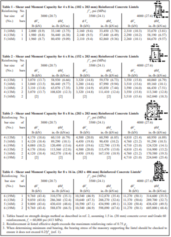
Tables 1 through 4 list design moment and shear strengths for various precast lintel sizes and concrete strengths, based on the following criteria (ref. 2).

Flexural strength:

Shear strength, no shear reinforcement:

ACI 318 contains requirements for minimum and maximum reinforcing steel areas to ensure a minimum level of performance. Minimum reinforcement area for lintels is As min = 3(f’c)½bd/fy but not less than 200bd/fy. In addition, the reinforcement ratio is limited to 75% of the balanced reinforcement ratio, ρmax = 0.75ρb.

Deflection criteria for lintels is based on controlling cracking in the masonry being supported. Consequently, less deflection is allowed when the lintel supports unreinforced masonry. In this case, lintel deflection is limited to the effective span of the lintel (measured in inches) divided by 600 (L/600) (ref. 1). In addition, ACI 318 limits precast lintel deflection to L/240 when the element supported by the lintel is not likely to be damaged by large deflections, and L/480 when the element supported by the lintel is likely to be damaged by large deflections. Lintel deflection is calculated based on the effective moment of inertia, Ie, as follows (ref. 2, Section 9.5.2.3).

Shrinkage and creep due to sustained loads cause additional long-term deflections over and above those occurring when loads are first applied. ACI 318 requires that deflections due to shrinkage and creep are included, and provides an expression to estimate this additional deflection (ACI 318 Section 9.5.2.5):

λ = ξ/(1+50ρ’)

where ξ = 2.0 for exposures of 5 years or more.

DESIGN EXAMPLE

The residential basement wall shown in Figure 3 needs a lintel over the window opening. The floor live load is 400 lb (1.8 kN) per joist and the floor dead load is 100 lb (0.44 kN) per joist. Consider the floor joist loads, spaced at 16 in. (406 mm) on center, as uniformly distributed. Use a lintel self-weight of 61 lb/ ft (0.89 kN/m) and weight of 77.9 lb/ft2 (3.73 kPa) for the bond beam at the top of the wall over the lintel.

Determine effective depth, d: Assuming an 8 in. (203 mm) high lintel with two No. 4 (13M) bars,
d = 7.625 in. – 1.5 in. – 0.5/2 in.
= 5.88 in. (149 mm)

Check for arching action: The effective span length, L = 96 + 5.88 = 101.9 in. (2588 mm). Since the height of masonry above the opening is less than L/2, arching of the masonry over the opening cannot be assumed (see ref. 4 for detailed information about determining arching action).

Determine design loads:
LL = (400 lb)(12/16 in.) = 300 lb/ft (4.4 kN/m)
Dead loads include floor, wall, and lintel self-weight.
Dfloor = 100 lb (12/16 in.) = 75 lb/ft (1.1 kN/m)
Dlintel = 61 lb/ft (0.89 kN/m)
Db beam = (77.9lb/ft²)(7.625/12 ft)= 50 lb/ft (0.31 kN/m)
Dtotal = (75 + 61 + 50) = 186 lb/ft (3.2 kN/m)

For deflection calculations use loads as given above. For strength design multiply live loads by 1.7 and dead loads by 1.4. Maximum moment and shear for strength design:

Mmax = wL²/8
= {[(1.7)(300)+(1.4)( 186 ) lb/ft](101.9 in.)²/8}(ft/12 in.)
= 83,328 in.-lb (9.4 kN m)

Vmax = wL/2 (at distance “d” from support) (ref.2)
= [(1.7)(300)+(1.4)(186 lb/ft)](101.9/2-5.88 in.)(ft/12 in.)
= 2,893 lb (12.9 kN)

From Table 3, an 8 x 8 in. (203 x 203 mm) lintel with two No. 4 (13M) bars and f ‘c = 4000 psi (20.7 MPa) has sufficient strength.

Check deflection: Deflection is determined using the effective moment of inertia of the lintel, Ie, calculated as follows (ref. 2).

Ec = wc1.533(f’c)½ = (150 pcf)1.533(4000 psi)½
= 3,834,000 psi (26,400 MPa)
fr = 7.5(f’c)½ = 474 psi (3.3 MPa)
yt = 7.625 in./2 = 3.81 in. (97 mm)
Ig = bh³/12 = (7.625 in.)(7.625 in.)³/12
= 282 in.4 (11,725 cm4)
Mcr = frIg/yt = 474 psi(282 psi)/3.81 in.
= 35,083 in.-lb (4.0 kN⋅m)
Mmax uf = wL²/8 = [(300+186 lb/ft)(101.9 in.)²/8](ft/12 in.)
= 52567 in.-lb (5.9 kN⋅m)
(Mcr/Mmax uf)³ = (35,083/52567)³ = 0.297
n = Es/Ec = 29,000,000/3,834,000 = 7.6
ρ = As/bd = 0.40 in.²/(7.625 in.)(5.88 in.) = 0.00892
= 7.6(0.00892) = 0.0678
c = nρd[(1 + 2/)½ – 1]
= 0.0678(5.88 in.)[(1+ 2/0.0678)½-1] = 1.80 in. (45 mm)
Icr = bc³/3 + nAs (dc
= 7.625 in.(1.8 in.)³/3 + 7.6(0.4 in.²)(5.88 – 1.8)²
= 65.4 in.4 (2714 cm4)
Ie = (Mcr/Mmax ufIg + [1- (Mcr/Mmax uf)³]Icr
= 0.297(282) + [1-0.297]65.4 in.4
= 130 in.4 (5411 cm4) < Ig OK

For a simply supported beam under uniform load,

max = 5wL4/384EcIe
= 5(300 + 186 lb/ft)(101.9 in.)4/[384(3,834,000 psi)(130 in.4)]/(12 in./ft)
= 0.114 in. (2.9 mm)

Long-term deflection multiplier,
λ = ξ/(1+50ρ’) = 2/[1 + 50(0)] = 2

Long-term deflection,
LT = λ∆max = 2(0.114 in.) = 0.228 in. (5.8 mm)

Total deflection,
tot = max + LT = 0.114 + 0.228 = 0.342 in. (8.7 mm)

Deflection limit for this case is L/240 = 101.9 in./240
= 0.42 in. (10.7 mm) > 0.342 in. (8.7 mm) OK

NOTATIONS

a             = depth of equivalent rectangular stress block, in. (mm)
As           = area of tension reinforcement, in.² (mm²)
b             = actual width of lintel, in. (mm)
c              = distance from extreme compression fiber to neutral axis, in. (mm)
C             = resultant compressive force in concrete, lb (kN)
d              = distance from extreme compression fiber to centroid of tension reinforcement, in. (mm)
Db beam   = dead load of bond beam, lb/ft (kN/m)
Dfloor      = dead load of floor, lb/ft (kN/m)
Dlintel      = dead load of lintel, lb/ft (kN/m)
Dtot         = total design dead load, lb/ft (kN/m)
Ec            = modulus of elasticity of concrete, psi (MPa)
f ‘c           = specified compressive strength of concrete, psi (MPa)
fr             = modulus of rupture of concrete, psi (MPa)
fy             = specified yield strength of reinforcement, psi (MPa) (60,000 psi, 413 MPa)
Icr            = moment of inertia of cracked section transformed to concrete, in.4 (cm4)
Ie              = effective moment of inertia, in.4 (cm4)
Ig              = moment of inertia of gross concrete section about centroidal axis, in.4 (cm4)
L               = effective length, clear span plus depth of member, not to exceed the distance between center of supports, in. (mm)
LL             = live load, lb/ft (kN/m)
Mcr           = cracking moment, in.-lb (kN⋅m)
Mmax        = maximum factored moment on section, in.-lb (kN⋅m)
Mmax uf     = maximum unfactored moment on section, in.-lb (kN⋅m)
Mn             = nominal moment strength, in.-lb/ft (kN⋅m/m)
n                = modular ratio, Es/Ec
T                = resultant tensile force in steel reinforcement, lb (kN)
Vmax          = maximum factored shear on section, lb (kN)
Vn               = nominal shear strength, lb (kN)
w                = uniform load, lb/in. (kN/m)
wc               = density of concrete, pcf (kN/m³)
yt                = distance from centroidal axis of gross section to extreme fiber in tension, in. (mm)
max          = maximum immediate deflection, in. (mm)
LT            = long-term deflection, in. (mm)
tot            = total deflection, in. (mm)
εc               = strain in concrete, in./in. (mm/mm)
εs               = strain in steel reinforcement, in./in. (mm/mm)
ξ                 = time-dependent factor for sustained load
λ                 = multiplier for additional long-term deflection
Φ                = strength reduction factor
ρ                 = reinforcement ratio, As/bd
ρ’                = reinforcement ratio for nonprestressed compression reinforcement, As/bd
ρb               = reinforcement ratio producing balanced strain conditions
ρmax           = limit on reinforcement ratio

REFERENCES

  1. Building Code Requirements for Masonry Structures, ACI 530-99/ASCE 5-99/TMS 402-99. Reported by the Masonry Standards Joint Committee, 1999.
  2. Building Code Requirements for Structural Concrete, ACI 318-99. American Concrete Institute, 1999.
  3. ASD of CM Lintels Based on 2012 IBC/2011 MSJC, TEK 17-01D, Concrete Masonry & Hardscapes Association, 2011.

Strength Design of Reinforced Concrete Masonry Foundation Walls

INTRODUCTION

Although concrete masonry foundation walls can be constructed without reinforcing steel, reinforcement may be required for walls supporting large soil backfill loads. The strength design provisions found in Chapter 3 of Building Code Requirements for Masonry Structures (ref. 1) typically provides increased economy over the allowable stress design method, as thinner walls or larger reinforcing bar spacings often result from a strength design analysis. Strength design criteria are presented in detail in TEK 14-04B, Strength Design Provisions for Concrete Masonry (ref. 2).

DESIGN LOADS

Soil imparts lateral loads on foundation walls. The load is assumed to increase linearly with depth, resulting in a triangular load distribution on the wall. This lateral soil load is expressed as an equivalent fluid pressure, with units of pounds per square foot per foot of depth (kN/m²/m). For strength design analysis, this lateral soil pressure is increased by multiplying by a load factor, which provides a factor of safety against overload conditions. The maximum moment on the wall depends on the total wall height, the soil backfill height, the wall support conditions, the factored soil load, the existence of any surcharges on the soil and the presence of saturated soils.

Foundation walls also provide support for the structure above the foundation, transferring vertical loads to the footing. Vertical compression counteracts flexural tension, increasing the wall’s resistance to flexure. In low-rise construction, these vertical loads are typically small in relation to the compressive strength of the concrete masonry. Vertical load effects are not addressed in this TEK.

DESIGN TABLES

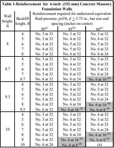
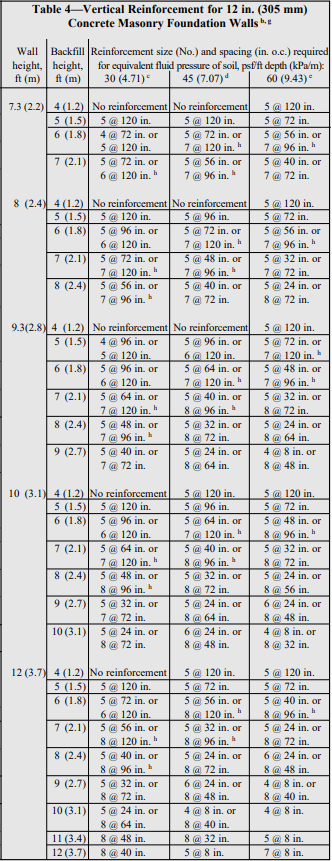
Tables 1 through 4 present reinforcement schedules for 6, 8, 10 and 12-in. (152, 203, 254 and 305-mm) walls, respectively. Additional reinforcement alternatives may be appropriate, and can be verified with an engineering analysis. Walls from 8 to 16 ft (2.4 to 4.9 m) high and soil pressures of 30, 45 and 60 psf/ft (4.7, 7.0, and 9.4 kN/m²/m) are included.

The effective reinforcement depth, d, assumed for the analyses are practical values, taking into account variations in face shell thickness, a range of reinforcing bar sizes, minimum required grout cover and construction tolerances for placing the reinforcement.

The following assumptions also apply to the values in Tables 1 through 4:

  1. there are no surcharges on the soil adjacent to the wall,
  2. there are negligible axial loads on the wall,
  3. the wall is simply supported at top and bottom,
  4. the wall is grouted at cells containing reinforcement (although solid grouting is acceptable),
  5. section properties are based on minimum face shell and web thickness requirements of ASTM C 90 (ref. 3),
  6. the specified compressive strength of masonry, f’m, is 1500 psi (10.3 MPa),
  7. Grade 60 (413 MPa) reinforcement,
  8. reinforcement requirements listed account for a soil load factor of 1.6 (ref. 6),
  9. the maximum width of the compression zone is limited to six times the wall thickness, or a 72 in. (1,829 mm) vertical bar spacing, whichever is smaller,
  10. reinforcing steel is placed toward the tension (interior) face of the wall (as shown in Figure 1), and
  11. the soil is well drained to preclude the presence of saturated soil.

DESIGN EXAMPLE

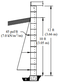
Wall: 12-in. (305 mm) thick concrete masonry foundation wall, 12 ft (3.66 m) high

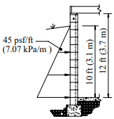
Soil: equivalent fluid pressure is 45 psf/ft (7.0 kN/m²/m) (excluding soil load factors), 10 ft (3.05 m) backfill height

Using Table 4, the wall can be adequately reinforced using No. 9 bars at 72 in. o.c. (M# 29 at 1,829 mm).

CONSTRUCTION ISSUES

This section discusses those issues which directly relate to structural design assumptions. See TEK 03-11, Concrete Masonry Basement Wall Construction and TEK 05-03A, Concrete Masonry Foundation Wall Details (refs. 4, 5) for more complete information on building concrete masonry foundation walls.

Figure 1 illustrates wall support conditions, drainage and protection from water. Before backfilling, the floor diaphragm must be in place, or the wall must be properly braced to resist the soil load. Ideally, the backfill should be free-draining granular material, free from expansive soils or other deleterious materials.

The assumption that there are no surcharges on the soil means that heavy equipment should not be operated directly adjacent to any basement wall system. In addition, the backfill materials should be placed and compacted in several lifts. Care should be taken when placing backfill materials to prevent damaging the drainage, waterproofing or exterior insulation systems.

REFERENCES

  1. Building Code Requirements for Masonry Structures, ACI 530-02/ASCE 5-02/TMS 402-02. Reported by the Masonry Standards Joint Committee, 2002.
  2. Strength Design Provisions for Concrete Masonry, TEK 14-04B, Concrete Masonry & Hardscapes Association, 2008.
  3. Standard Specification for Loadbearing Concrete Masonry Units, ASTM C 90-03. ASTM International, 2003.
  4. Concrete Masonry Basement Wall Construction, TEK 0311, Concrete Masonry & Hardscapes Association, 2001.
  5. Concrete Masonry Foundation Wall Details, TEK 05-03A, Concrete Masonry & Hardscapes Association, 2003.
  6. Minimum Design Loads for Buildings and Other Structures, ASCE 7-02. American Society of Civil Engineers, 2002.


Allowable Stress Design of Concrete Masonry Foundation Walls

INTRODUCTION

Basements provide: economical living, working and storage areas; convenient spaces for mechanical equipment; safe havens during tornadoes and other violent storms; and easy access to plumbing and ductwork. Concrete masonry is well suited to basement and foundation wall construction due to its inherent durability, compressive strength, economy, and resistance to fire, termites, and noise.

Traditionally, residential basement walls have been constructed of plain (unreinforced) concrete masonry, often designed empirically. Walls over 8 ft (2.4 m) high or with larger soil loads are typically designed using reinforced concrete masonry or using design tables included in building codes such as the International Building Code (ref. 4).

DESIGN LOADS

Soil imparts a lateral load on foundation walls. For design, the load is traditionally assumed to increase linearly with depth resulting in a triangular load distribution. This lateral soil load is expressed as an equivalent fluid pressure, with units of pounds per square foot per foot of depth (kPa/m). The maximum force on the wall depends on the total wall height, soil backfill height, wall support conditions, soil type, and the existence of any soil surcharges. For design, foundation walls are typically assumed to act as simple vertical beams laterally supported at the top and bottom.

Foundation walls also provide support for the structure above, transferring vertical loads to the footing. When foundations span vertically, this vertical compression counteracts flexural tension, increasing the wall’s resistance to flexure. In low-rise construction, these vertical loads are typically small in relation to the compressive strength of concrete masonry. Further, if the wall spans horizontally, vertical compression does not offset the flexural tension. Vertical load effects are not included in the tables and design example presented in this TEK (references 2 and 3 include vertical load effects).

EMPIRICAL DESIGN

The empirical design method uses historical experience to proportion and size masonry elements. Empirical design is often used to design concrete masonry foundation walls due to its simplicity and history of successful performance.

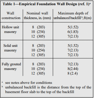
Table 1 lists the allowable backfill heights for 8, 10 and 12-inch (203, 254 and 305 mm) concrete masonry foundation walls. Table 1 may be used for foundation walls up to 8 feet (2.4 m) high under the following conditions (ref. 1):

  1. terrain surrounding the foundation wall is graded to drain surface water away from foundation walls,
  2. backfill is drained to remove ground water away from foundation walls,
  3. tops of foundation walls are laterally supported prior to backfilling,
  4. the length of foundation walls between perpendicular masonry walls or pilasters is a maximum of 3 times the foundation wall height,
  5. the backfill is granular and soil conditions in the area are non-expansive,
  6. masonry is laid in running bond using Type M or S mortar, and
  7. units meet the requirements of ASTM C 90 (ref. 6).

Where these conditions cannot be met, the wall must be engineered using either an allowable stress design (see following section) or strength design procedure (see ref. 5).

WALL DESIGN

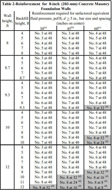
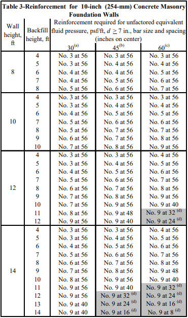
Tables 2 through 4 of this TEK have been rationally designed in accordance with the allowable stress design provisions of Building Code Requirements for Masonry Structures (ref. 1) and therefore meet the requirements of the International Building Code even though the latter limits reinforcment spacing to 72 in. (1829 mm) when using their tables. Additional reinforcement alternatives may be appropriate and can be verified with an engineering analysis.

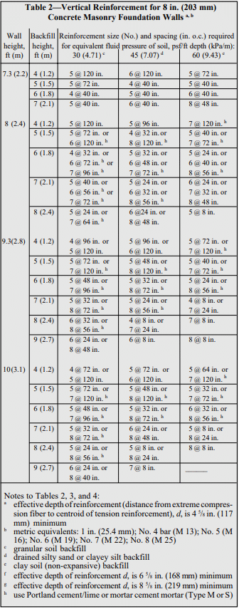
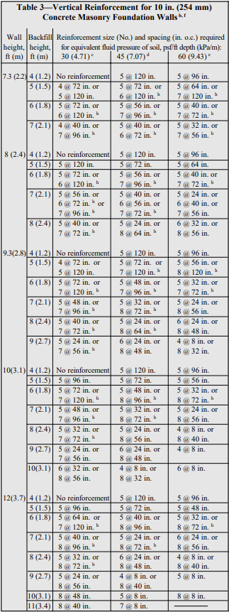
Tables 2, 3 and 4 list reinforcement options for 8, 10 and 12-in. (203, 254 and 305-mm) thick walls, respectively. The effective depths of reinforcement, d, (see Table notes) used are practical values, taking into account variations in face shell thickness, a range of bar sizes, minimum required grout cover, and construction tolerances for placing the reinforcing bars.

Tables 2 through 4 are based on the following:

  1. no surcharges on the soil adjacent to the wall and no hydrostatic pressure,
  2. negligible axial loads on the wall,
  3. wall is simply supported at top and bottom,
  4. wall is grouted only at reinforced cells,
  5. section properties are based on minimum face shell and web thicknesses in ASTM C 90 (ref. 6),
  6. specified compressive strength of masonry, f’m, is 1,500 psi (10.3 MPa),
  7. reinforcement yield strength, fy, is 60,000 psi (414 MPa),
  8. modulus of elasticity of masonry, Em, is 1,350,000 psi (9,308 MPa),
  9. modulus of elasticity of steel, Es, is 29,000,000 psi (200,000 MPa),
  10. maximum width of compression zone is six times the wall thickness (where reinforcement spacing exceeds this distance, the ability of the plain masonry outside the compression zone to distribute loads horizontally to the reinforced section was verified assuming two-way plate action),
  11. allowable tensile stress in reinforcement, Fs, is 24,000 psi (165 MPa),
  12. allowable compressive stress in masonry, Fb, is f’m (500 psi, 3.4 MPa),
  13. grout complies with ASTM C 476 (2,000 psi (14 MPa) if property spec is used) (ref. 7), and
  14. masonry is laid in running bond using Type M or S mortar and face shell mortar bedding.

DESIGN EXAMPLE

Wall: 12-inch (305 mm) thick, 12 feet (3.7 m) high.

Loads: equivalent fluid pressure of soil is 45 pcf (7.07 kPa/ m), 10 foot (3.1 m) backfill height. No axial, seismic, or other loads.

Using Table 4, #8 bars at 40 in. (M 25 at 1016 mm) o.c. are sufficient.

CONSTRUCTION ISSUES

This section is not a complete construction guide, but rather discusses those issues directly related to structural design assumptions. Figures 1 and 2 illustrate typical wall support conditions, drainage, and water protection.

Before backfilling, the floor diaphragm must be in place or the wall must be properly braced to resist the soil load. In addition to the absence of additional dead or live loads following construction, the assumption that there are no surcharges on the soil also means that heavy equipment should not be operated close to basement wall systems that are not designed to carry the additional load. In addition, the backfill materials should be placed and compacted in several lifts, taking care to prevent wall damage. Care should also be taken to prevent damaging the drainage, waterproofing, or exterior insulation systems, if present.

REFERENCES

  1. Building Code Requirements for Masonry Structures, ACI 530-99/ASCE 5-99/TMS 402-99. Reported by the Masonry Standards Joint Committee, 1999.
  2. International Building Code. International Code Council, 2000.
  3. Strength Design of Reinforced CM Foundation Walls, TEK 15-02B, Concrete Masonry & Hardscapes Association, 2004.
  4. Standard Specification for Loadbearing Concrete Masonry Units, ASTM C 90-01. American Society for Testing and Materials, 2001.
  5. Standard Specification for Grout Masonry, ASTM C476- 01. American Society for Testing and Materials, 2001.