Varying the bond or joint pattern of a concrete masonry wall can create a wide variety of interesting and attractive appearances using standard units as well as sculptured-face and other architectural units. Because concrete masonry is often used as the finished wall surface, the use of bond patterns other than the traditional running bond has steadily increased for both loadbearing and nonloadbearing walls.
Building code allowable design stresses, lateral support, and minimum thickness requirements for concrete masonry are based primarily on structural testing and research on wall panels laid in running bond construction. When a different bond pattern is used it is advisable to consider its influence on the compressive and flexural strength of a block wall. Some building codes provide for variations in bond pattern to some extent by requiring the use of horizontal reinforcement, for example, when walls are laid in stack bond.
STACK BOND CONSTRUCTION
Excluding running bond construction, the most popular and widely used bond pattern with concrete masonry units is stack bond. Compressive strength is similar for stack and running bond construction. In stack bond masonry, heavy concentrated loads will be carried down to the support by the particular vertical tier or “column” of masonry under the load, with little distribution to adjacent masonry. Stability will not be jeopardized if allowable stresses are not exceeded, but the use of reinforced bond beams will aid in distributing concentrated loads. The use of pilasters or grouted cells will also be effective in increasing the resistance to concentrated loads.
The flexural strength of stack bond walls spanning horizontally can be increased significantly by the use of bond beams or joint reinforcement. The value of joint reinforcement as a means of strengthening concrete masonry in the horizontal span is indicated in Figure 4 which shows the relative flexural strength with and without joint reinforcement. From this it can be seen that properly reinforced stack bond masonry can be designed to be as strong as running bond construction.
CODE REQUIREMENTS
Building Code Requirements for Masonry Structures (ref. 1) includes criteria for walls laid in stack bond. Although stack bond typically refers to masonry constructed such that the head joints are vertically aligned, the Code defines stack bond as masonry laid such that the head joints in successive courses are horizontally offset less than one quarter the unit length, as illustrated in Figure 1.
All stack bond construction is required to have a minimum area of horizontal reinforcement equal to 0.00028 times the gross vertical cross-sectional area of the wall. This requirement can be met using either bond beams spaced not more than 48 in. (1219 mm) on center or using joint reinforcement. Anchored masonry veneer must have horizontal joint reinforcement, of at least one wire size W1.7 (9 gauge) (MW11) or larger, spaced at a maximum of 18 in. (457 mm) on center vertically. This is equivalent to the minimum reinforcement stated above for a nominal 4 in. (102 mm) wythe.
When stack bond construction may be subjected to seismic loads or winds of hurricane velocity, consideration must be given to additional requirements and restrictions as may be consistent with local codes, local experience, and engineering practice. For example, Building Code Requirements for Masonry Structures requires stack bond masonry in Seismic Design Category D and higher to be solidly grouted hollow open-end units, fully grouted hollow units with full head joints, or solid units with a maximum spacing of 24 in. (610 mm) for the reinforcement. Seismic Design Category E & F have an additional requirement that the horizontal reinforcement be at least 0.0015 the gross cross-sectional area of walls that are not part of the lateral-force resisting system. For walls that are part of the lateral force resisting system in SDC E & F, the minimum horizontal reinforcement requirement is increased to 0.0025 times the gross cross-sectional area with a maximum spacing of 16 in. (406 mm). These elements also must be solidly grouted hollow open end units or two wythes of solid units.
Figure 1—Definition of Stack Bond Masonry
TESTING PROGRAM
To assist in evaluating the structural performance of walls laid with various bond patterns, a large number of concrete masonry panels were tested for compressive and flexural strength (ref. 2). The nine bond patterns shown in Figure 2 were employed in constructing the test panels. Panels were composed of 8 in. (203 mm) hollow units laid up with Types M and S mortar with face shell bedding. Panels were 4 ft wide by 8 ft high (1.2 by 2.4 m); those for flexural strength tests with the wall spanning horizontally between supports were 8 ft wide by 4 ft high (2.4 by 1.2 m). For compressive strength tests, loading was applied at an eccentricity of one-sixth of the wall thickness. Lateral tests used uniformly distributed loading from a plastic bag filled with air. Test methods and details followed those specified in Standard Methods of Conducting Strength Tests of Panels for Building Construction, ASTM E 72 (ref. 3)
Relative strengths of the wall panels are compared by bond pattern in Figure 3 using 8 in. (203 mm) high units laid in running bond as the standard.
Figure 2—Concrete Masonry Patterns for Structural Tests
Compressive Strengths
From Figure 3 it is evident that where hollow units are laid in the horizontal position there is no decrease in wall compressive strength for the different bonding patterns. Units laid in the vertical or diagonal position generally produce wall strengths approximately 75% of that obtained from the running bond pattern. The reduction in strength for vertical stack bond is directly related to the decrease in net block area in compression. In the vertical position, the end webs and interior webs are so oriented with respect to the direction of stress that they do not contribute to the strength of the wall except as ties between the face shells. When blocks are laid in the horizontal position, the end and middle webs are parallel to the direction of stress and contribute to the strength of the wall.
Figure 3—Relative Strengths of Walls Laid in Different Bond Patterns
Vertical Span Flexural Strength
Where walls span vertically between lateral supports, failure from transverse loading occurs as a bond failure between block and mortar. Only three of the bond patterns tested showed a decrease in flexural strength when compared to the standard: vertical stack, basket weave “B”, and coursed ashlar. In two of these patterns the continuous horizontal joints are farther apart than the standard running bond pattern. Horizontal stack bond construction was 30% stronger in vertical span flexure, and walls built with units laid in a diagonal position were more than 50% stronger because more mortar bond area is included in the “saw-tooth” line across the wall width.
Horizontal Span Flexural Strength
For unreinforced concrete masonry laid in running bond and spanning horizontally between lateral supports, flexural resistance depends on the strength and design of the block. Under increasing lateral load the units will rupture in tension rather than failing by mortar bond. For this reason, walls are generally at least twice as strong in flexure when spanning horizontally. This does not apply to walls laid in stack bond, which have approximately the same strength in both directions. Test results shown in Figure 4 indicate that the relative strength of stack bond walls in the horizontal span is about 30% of running bond construction.
Figure 4—Relative Flexural Strength in Horizontal Span of Concrete Masonry Walls With and Without Joint Reinforcement
REFERENCES
Building Code Requirements for Masonry Structures, ACI 530-02/ASCE 5-02/TMS 402-02. Reported by the Masonry Standards Joint Committee, 1999.
Providing a quality indoor acoustic environment is becoming a higher priority in many cases; particularly in urban environments where noise from traffic and other outside sources can be a significant distraction, especially in schools, homes and the workplace. Concrete masonry walls provide excellent noise control due to their ability to effectively block airborne sound transmission over a wide range of frequencies.
The ability of a wall to insulate a building interior from outdoor noise can be indicated by the wall’s outdoor-indoor transmission class (OITC), with higher OITC values indicating better sound insulation.
OITC is one rating system available to help compare the acoustic performance of various wall systems. Others include the sound transmission class (STC) and the noise reduction coefficient (NRC). Both OITC and STC indicate a wall’s ability to block the transmission of sound from one side of the wall to the other. OITC differs from the STC rating in that the OITC was developed specifically to indicate transmission of noise from transportation sources. STC was developed primarily for indoor noise sources, such as human speech. Unlike OITC and STC, NRC indicates the ability of a wall to absorb sound, which is useful for controlling sound reverberations within a room.
This TEK presents OITC values for a variety of common concrete masonry exterior walls. STC and NRC values for concrete masonry walls can be found in TEK 13-01D, Sound Transmission Class Ratings for Concrete Masonry Walls, and TEK 13-02A, Noise Control With Concrete Masonry (refs. 1, 2), respectively.
OUTDOOR-INDOOR TRANSMISSION CLASS
The OITC is a rating intended for exterior building facades, and is an estimate of a wall’s or window’s ability to reduce typical transportation noise. It is determined in accordance with ASTM E1332, Standard Classification for Rating Outdoor-Indoor Sound Attenuation (ref. 3). E1332 presents a standard procedure to calculate OITC based on tested sound transmission loss (TL) across the wall or wall element at specific frequencies from 80 to 4,000 Hz. These TL values are measured either in the laboratory or in the field using ASTM E90, Standard Test Method for Laboratory Measurement of Airborne Sound Transmission Loss of Building Partitions and Elements, or ASTM E966, Standard Guide for Field Measurements of Airborne Sound Attenuation of Building Facades and Facade Elements (refs. 4, 5).
OITC is calculated using these tested TL values along with the sound spectrum of a reference sound source. This reference sound spectrum is an average of typical spectra from three transportation noise sources: aircraft takeoff, freeway and railroad passby. The reference sound spectrum is A-weighted to better correlate to human hearing (A-weighting is a frequency response adjustment that accounts for the changes in human hearing sensitivity as a function of frequency).
Although higher OITC values indicate more effective sound insulation from noises similar to the reference sound spectrum, it should be noted that the accuracy of the rating depends on the actual exterior noise spectrum and the surface area of the wall, as well as the acoustic performance of other building elements, such as windows and doors. The OITC is intended to be used to compare various facades, rather than as a predictor of performance.
The OITC can be applied to walls, doors, windows, or combinations thereof. As presented in this TEK, the OITC values apply to the masonry portion of the wall only, without windows or other openings.
CONCRETE MASONRY OITC VALUES
OITC Values Based on Test Data
Many ASTM E90 sound transmission loss tests have been performed on a wide variety of concrete masonry walls. OITC values for some of these walls have been calculated in accordance with ASTM E1332 from E90 test data, and are presented in Table 1. In general, for concrete masonry walls, heavier walls have higher OITC values.
Note that the ASTM E1332 OITC calculation requires transmission loss (TL) test data from 80 Hz to 4,000 Hz, while ASTM E90 test reports often do not include TL values at 80 Hz. Test reports which do include 80 Hz show that the TL value of concrete masonry walls at 80 Hz is typically about the same or higher than that at 100 Hz. For the purposes of this TEK, where TL values at 80 Hz were not reported, the 80 Hz TL was assumed equal to the 100 Hz TL.
OITC values can also be determined by field testing, using test data from ASTM E966, then calculated in accordance with E1332.
Estimated OITC in the Absence of Test Data
Ideally, OITC should be based on tested transmission loss values. In recognition that this data is not always available, however, the information in Figure 1 is presented as a tool to help designers estimate OITC values.
It has been well established (ref. 6) that the STC of concrete masonry walls is directly related to wall weight. Using this knowledge and the calculated OITC values in Table 1, a correlation between concrete masonry wall weight and OITC has been developed for walls at least 3 in. (76 mm) thick:
where W = the average wall weight based on the weight of the masonry units; the weight of mortar, grout and loose fill material in voids within the wall; and the weight of plaster, stucco and paint, psf (kg/m²). The weight of drywall is not included.
Table 1 contains calculated OITC values for various concrete masonry walls, based on Equation 1.
For multi-wythe walls where both wythes are concrete masonry, the weight of both wythes is used in Equation 1. For multi-wythe walls having both concrete masonry and clay brick wythes, however, a different procedure must be used, because concrete and clay masonry have different acoustical properties. In this case, Equation 2, representing a best-fit relationship for clay masonry, must also be used. To determine a single OITC for the wall system, first calculate the OITC using both Equations 1 and 2, using the combined weight of both wythes, then linearly interpolate between the two resulting OITC ratings based on the relative weights of the wythes. Equation 2 is the OITC equation for clay masonry (ref. 1):
Tabulated wall weights for concrete masonry walls can be found in CMU-TEC-002-23, Weights and Section Properties of Concrete Masonry Assemblies (ref. 7).
For example, consider a masonry cavity wall with an 8-in. (203-mm) concrete masonry backup wythe (W = 33 psf, 161 kg/m²) and a 4-in. (102-mm) clay brick veneer (W = 38 psf, 186 kg/m²).
Table 1—Calculated OITC Ratings for Concrete Masonry Walls (ref. 6)
Figure 1—OITC Estimates Sound Insulation From Common Traffic Sources
OITC REQUIREMENTS
Although not currently required by the International Building Code (ref. 8), designers sometimes include an OITC requirement in the construction documents, particularly for buildings close to railroads, airports and highways.
DESIGN AND CONSTRUCTION
In addition to transmission class values for walls, other factors also affect the acoustical environment of a building. Seemingly minor construction details can impact the acoustic performance of a wall. For example, screws used to attach gypsum wallboard to steel furring or resilient channels should not be so long that they contact the face of the concrete masonry substrate, as this contact area becomes an effective path for sound vibration transmission.
Through-wall openings, partial wall penetration openings and inserts, such as electrical boxes, as well as control joints should be completely sealed.
The reader is referred to TEK 13-01D, Sound Transmission Class Ratings for Concrete Masonry Walls, and TEK 13-02A, Noise Control With Concrete Masonry (refs. 1, 2) for more detailed information on the above as well as additional design and building layout considerations to help minimize sound transmission.
REFERENCES
Sound Transmission Class Ratings for Concrete Masonry Walls, TEK 13-01D. Concrete Masonry & Hardscapes Association, 2012.
Noise Control With Concrete Masonry, TEK 13-02A. Concrete Masonry & Hardscapes Association, 2007.
Standard Classification for Rating Outdoor-Indoor Sound Attenuation, ASTM E1332-10a. ASTM International, 2010.
Standard Test Method for Laboratory Measurement of Airborne Sound Transmission Loss of Building Partitions and Elements, ASTM E90-09. ASTM International, 2009.
Standard Guide for Field Measurements of Airborne Sound Attenuation of Building Facades and Facade Elements, ASTM E966-10e1. ASTM International, 2010.
Standard Method for Determining The Sound Transmission Rating for Masonry Walls, TMS 0302-12. The Masonry Society, 2012.
Weights and Section Properties of Concrete Masonry Assemblies, CMU-TEC-002-23, Concrete Masonry & Hardscapes Association, 2023.
2003, 2006, 2009, and 2012 International Building Code. International Code Council, 2003, 2006, 2009, 2012.
TEK 13-04A, Revised 2012. CMHA and the companies disseminating this technical information disclaim any and all responsibility and liability for the accuracy and the application of the information contained in this publication.
Unwanted noise can be a major distraction, whether at school, work or home. Concrete masonry walls are often used for their ability to isolate and dissipate noise. Concrete masonry offers excellent noise control in two ways. First, it effectively blocks airborne sound transmission over a wide range of frequencies. Second, concrete masonry effectively absorbs noise, thereby diminishing noise intensity. Because of these abilities, concrete masonry has been used successfully in applications ranging from party walls to hotel separation walls, and even highway sound barriers.
Sound is caused by vibrations transmitted through air or other mediums, and is characterized by its frequency and intensity. Frequency (the number of vibrations or cycles per second) is measured in hertz (Hz). Intensity is measured in decibels (dB), a relative logarithmic intensity scale. For each 20 dB increase in sound there is a corresponding tenfold increase in pressure.
This logarithmic scale is particularly appropriate for sound because the perception of sound by the human ear is also logarithmic. For example, a 10 dB sound level increase is perceived by the ear as a doubling of the loudness.
The speed of sound through a particular medium, such as a party wall, depends on both the density and stiffness of the medium. All solid materials have a natural frequency of vibration. If the natural frequency of a solid is at or near the frequency of the sound which strikes it, the solid will vibrate in sympathy with the sound, which will be regenerated on the opposite side. The effect is especially noticeable in walls or partitions that are light, thin or flexible. Conversely, the vibration is effectively stopped if the partition is heavy and rigid, as is the case with concrete masonry walls. In this case, the natural frequency of vibration is relatively low, so only sounds of low frequency will cause sympathetic vibration. Because of its mass (and resulting inertia) and rigidity, concrete masonry is especially effective at reducing sound transmission.
DETERMINING SOUND TRANSMISSION CLASS (STC) FOR CONCRETE MASONRY
Sound transmission class (STC) provides an estimate of the acoustic performance of a wall in certain common airborne sound insulation applications.
The STC of a wall is determined by comparing sound transmission loss (STL) values at various frequencies to a standard contour. STL is the decrease or attenuation in sound energy, in dB, of airborne sound as it passes through a wall. In general, the STL of a concrete masonry wall increases with increasing frequency of the sound.
Many sound transmission loss tests have been performed on various concrete masonry walls. These tests have indicated a direct relationship between wall weight and the resulting STC—heavier concrete masonry walls have higher STC ratings. A wide variety of STC ratings is available with concrete masonry construction, depending on wall weight, wall construction and finishes.
In the absence of test data, standard calculation methods exist, which tend to be conservative. Standard Method for Determining Sound Transmission Ratings for Masonry Walls, TMS 0302 (ref. 1), contains procedures for determining STC values of concrete masonry walls. According to the standard, STC can be determined by field or laboratory testing in accordance with standard test methods or by calculation. The calculation in TMS 0302 is based on a best-fit relationship between concrete masonry wall weight and STC based on a wide range of test results in accordance with the following:
Equation 1 is applicable to uncoated fine- or medium- textured concrete masonry and to coated coarse-textured concrete masonry. Because coarse-textured units may allow airborne sound to enter the wall, they require a surface treatment to seal at least one side of the wall. At least one coat of acrylic latex, alkyd or cement-based paint, or plaster are specifically called out in TMS 0302, although other coatings that effectively seal the surface are also acceptable. One example is a layer of drywall with sealed penetrations, as shown in Figure 2. Architectural concrete masonry units are considered sealed without surface treatment for the purposes of using Equation 1.
Equation 1 also assumes the following:
walls have a thickness of 3 in. (76 mm) or greater,
hollow units are laid with face shell mortar bedding, with mortar joints the full thickness of the face shell,
solid units are fully mortar bedded, and
all holes, cracks and voids in the masonry that are intended to be filled with mortar are solidly filled.
Calculated values of STC are listed in Table 1.
Because the best-fit equation is based solely on wall weight, the calculation tends to underestimate the STC of masonry walls that incorporate dead air spaces, which contribute to sound attenuation. See the following section for the effect of drywall with furring spaces on STC.
For multi-wythe walls where both wythes are concrete masonry, the weight of both wythes is used in Equation 1 to determine STC. For multi-wythe walls having both concrete masonry and clay brick wythes, however, a different procedure must be used, because concrete and clay masonry have different acoustical properties. In this case, Equation 2, representing a best-fit relationship for clay masonry, must also be used. To determine a single STC for the wall system, first calculate the STC using both Equations 1 and 2, based on the combined weight of both wythes, then linearly interpolate between the two resulting STC ratings based on the relative weights of the wythes. Equation 2 is the STC equation for clay masonry (ref. 1):
For example, consider a masonry cavity wall with an 8-in. (203-mm) concrete masonry backup wythe (W = 33 psf, 161 kg/m²) and a 4-in. (102-mm) clay brick veneer (W = 38 psf, 186 kg/m²).
The installed weight of concrete masonry assemblies can be determined in accordance with CMU-TEC-002-23 (ref. 10). When STC tests are performed, the TMS 0302 requires the testing to be in accordance with ASTM E90, Standard Test Method for Laboratory Measurement of Airborne Sound Transmission Loss of Building Partitions and Elements (ref. 2) for laboratory testing or ASTM E413, Standard Classification for Rating Sound Insulation (ref. 3) for field testing.
CONTRIBUTION OF DRYWALL
Drywall attached directly to the surface of a concrete masonry wall has very little effect on sound attenuation other than the same benefit as sealing the surface. Adding ½ or ⅝ in. (13 or 16 mm) gypsum wall board to one side of the wall with an unfilled furring space will generally result in a slight increase in STC. However, when placed on both sides of the wall with a furring space of less than 0.8 in. (19 mm) a reduction in STC is realized due to mass-air-mass resonance similar to the action of drum. Better results are realized when the furring space is filled with sound insulation. Sound insulation consists of fibrous materials, such as cellulose fiber, glass fiber or rock wool insulation, are good materials for absorbing sound; closed-cell materials, such as expanded polystyrene, are not, as they do not significantly absorb sound (refs. 1, 7). Note that most of these materials are susceptible to moisture so care must be taken when applying these types of insulation to exterior walls.
Equations to determine the change in STC when adding drywall are as follows (Table 2 lists calculated values of ΔSTC based on Equations 3 through 6):
For drywall on one side of the wall with no sound absorbing material in the furring space:
For drywall on both sides of the wall and no sound absorbing material in the furring spaces:
For drywall on one side of the wall with sound absorbing material in the furring space:
For drywall on both sides of the wall and sound absorbing material in the furring spaces:
In addition to this TEK, CMHA has generated a calculator for determining the sound transmission class (STC) of a user defined assembly. See CMU-XLS-003-19, CMU Sound and Assemblies Properties Calculator (ref. 8).
BUILDING CODE REQUIREMENTS
The International Building Code (ref. 4) contains requirements to regulate sound transmission through interior partitions separating adjacent dwelling units and separating dwelling units from adjacent public areas, such as hallways, corridors, stairs or service areas. Partitions serving the above purposes must have a sound transmission class of at least 50 dB for airborne noise when tested in accordance with ASTM E90. If field tested, an STC of 45 must be achieved. In addition, penetrations and openings in these partitions must be sealed, lined or otherwise treated to maintain the STC. Guidance on achieving this for masonry walls is contained below in Design and Construction.
The International Residential Code (ref. 5) contains similar requirements, but with a minimum STC rating of 45 dB when tested in accordance with ASTM E90 for walls and floor/ceiling assemblies separating dwelling units.
DESIGN AND CONSTRUCTION
In addition to STC values for walls, other factors also affect the acoustical environment of a building. For example, a higher STC may be warranted between a noisy room and a quiet one than between two noisy rooms. This is because there is less background noise in the quiet room to mask the noise transmitted through the common wall.
Seemingly minor construction details can also impact the acoustic performance of a wall. For example, screws used to attach gypsum wallboard to steel furring or resilient channels should not be so long that they contact the face of the concrete masonry substrate, as this contact area becomes an effective path for sound vibration transmission.
TMS 0302 includes requirements for sealing openings and joints to ensure these gaps do not undermine the sound transmission characteristics of the wall. These requirements are described below and illustrated in Figures 1 and 2.
Through-wall openings should be completely sealed, After first filling gaps with foam, cellulose fiber, glass fiber, ceramic fiber or mineral wool. Similarly, partial wall penetration openings and inserts, such as electrical boxes, should be completely sealed with joint sealant.
Control joints should also be sealed with joint sealants to minimize sound transmission. The joint space behind the sealant backing can be filled with mortar, grout, foam, cellulose fiber, glass fiber or mineral wool (see Figure 2).
To maintain the sound barrier effectiveness, partitions should be carried to the underside of the structural slab, and the joint between the two should be sealed against sound transmission in a way that allows for slab deflection. If the roof or floor is metal deck rather than concrete, joint sealants alone will not be effective due to the shape of the deck flutes. In this case, specially shaped foam filler strips should be used. For fire and smoke containment walls, safing insulation should be used instead of foam filler strips.
Additional nonmandatory design and building layout considerations will also help minimize sound transmission. These are covered in detail in TEK 13-02A (ref. 6). The design of exterior walls for the mitigation of outdoor-indoor sound transmission is covered under TEK 13-04B (ref. 9).
Table 1—Calculated STC Ratings for Concrete Masonry Walls (ref. 1)
Table 2—Increase in STC Ratings Due to Furring Space and Drywall (ref. 1)
Figure 1—Sealing Wall Intersections & Control Joints
Figure 2—Sealing Around Penetrations & Fixtures
NOTATIONS
ΔSTC = the change in STC rating compared to a bare concrete masonry wall d = the thickness of the furring space (when drywall is used on both sides of the masonry, d is the thickness of the furring space on one side of the wall only), in. (mm) STC = Sound Transmission Class STL = Sound Transmission Loss W = the average wall weight based on the weight of the masonry units; the weight of mortar, grout and loose fill material in voids within the wall; and the weight of surface treatments (excluding drywall) and other components of the wall, psf (kg/m²)
REFERENCES
Standard Method for Determining Sound Transmission Ratings for Masonry Walls, TMS 0302-12. The Masonry Society, 2012.
Standard Test Method for Laboratory Measurement of Airborne Sound Transmission Loss of Building Partitions and Elements, ASTM E90-09. ASTM International, 2009.
Standard Classification for Rating Sound Insulation, ASTM E413-10. ASTM International, 2010.
2003, 2006, 2009, and 2012 International Building Code. International Code Council, 2003, 2006, 2009, 2012.
2003, 2006, 2009, and 2012 International Residential Code. International Code Council, 2003, 2006, 2009, 2012.
Noise Control with Concrete Masonry, TEK 13-02A. Concrete Masonry & Hardscapes Association, 2007.
Controlling Sound Transmission Through Concrete Block Walls, Construction Technology Update No. 13. National Research Council of Canada, 1998.
Outdoor-Indoor Transmission Class of Concrete Masonry Walls, TEK 13-04A, Concrete & Masonry Hardscapes Association, 2012.
TEK 13-10D, Revised 2012. CMHA and the companies disseminating this technical information disclaim any and all responsibility and liability for the accuracy and the application of the information contained in this publication.
Self-consolidating grout (SCG) is a specially-formulated grout for use with reinforced masonry. It is designed to fill the long, narrow and sometimes highly congested cores of reinforced walls without the need for consolidation and reconsolidation by mechanical vibration or by puddling.
Self-consolidating grout has been used in various parts of the United States, under the grout demonstration panel provisions of Specification for Masonry Structures (refs. 1, 2), which is included by reference in the International Building Code (refs. 3, 4). The 2008 edition of Specification for Masonry Structures (ref. 5), however, includes explicit provisions for SCG.
Unlike conventional grout and conventional concrete, self consolidating grout (SCG) is a special application of self consolidating concrete (SCC) that uses aggregates complying with ASTM C 404, Standard Specification for Aggregates for Masonry Grout (ref. 6), as specified in ASTM C 476, Standard Specification for Grout for Masonry (ref. 7).
Similar to conventional grout, there are two types of selfconsolidating grout, coarse and fine, with the latter containing only fine aggregate. Coarse self-consolidating grout has been the most common, although fine SCG is predominant in several specific regions of the U.S.
MATERIALS FOR SELF-CONSOLIDATING GROUT
Self-consolidating grout attains a high flow not from adding more water, but from a careful mix design to create a flowable yet highly cohesive grout that will not segregate and can pass freely through congested reinforcement and narrow openings without “blocking or bridging.” SCG must maintain its fluidity without segregation and maintain consistent properties throughout the grout lift. It is composed of aggregates, cementitious materials, water and special admixtures which provide the fluidity and stability to meet performance requirements.
Aggregate Size and Proportion
To obtain the desired filling and placing ability, aggregates used in SCG should meet the requirements of ASTM C 404, as specified in ASTM C 476. The requirements for coarse aggregate, for use in coarse SCG, are essentially the same as the requirements for No. 8 and No. 89 coarse aggregate in ASTM C 33, Standard Specification for Concrete Aggregates (ref. 8): they should be either a Size No. 8 or Size No. 89 gravel, stone or air-cooled iron blast furnace slag with 100% passing the ½ in. (13 mm) sieve and at least 85 to 90% passing the 3/8 in. (9.5 mm) sieve. Fine aggregate, for use in either coarse or fine SCG, is typically Size No. 1, which is a concrete sand as defined in ASTM C 33, but could also be Size No. 2, which is a sand for masonry mortar as defined in ASTM C 144, Specification for Aggregate for Masonry Mortar (ref. 9).
ASTM C 476 contains a proportion specification as well as a performance specification for masonry grout. The proportion specification specifies that coarse grout should have fine aggregate in the amount of 2 1/4 to 3 times the sum of the volume of the cementitious materials and coarse aggregate in the amount of 1 to 2 times the sum of the volume of the cementitious materials. These ASTM C 476 requirements are equivalent to s/a (sand/total aggregate) ratios of approximately 0.50 to 0.60 on an absolute volume basis. By comparison, most self-consolidating concrete mix designs have similar s/a ratios in the 0.50 to 0.60 range.
Cementitious Materials and Minus 100 (0.150 mm) Sieve Content and Composition
Grout is required to have a minimum compressive strength of 2,000 psi (14 MPa) after 28 days of curing (ref. 7). Building Code Requirements for Masonry Structures (ref. 10) sets an upper limit on the specified compressive strength of grout at 5,000 psi (34.5 MPa) at 28 days when using strength design of concrete masonry, although experience indicates that many conventional grouts develop strengths greater than this specification limit. Note that actual strengths are somewhat higher than the specified strength to assure compliance.
In the historical context of masonry materials, the term cementitious materials has commonly referred to the cement content (as well as lime in the case of masonry mortars) used in the manufacturing of masonry units, mortar or grout. In the production of SCG, however, the fraction of very fine aggregate particles present in the mix can have a significant influence on the plastic (and by association, the hardened) properties of SCG, and therefore needs to be considered in the batching of SCG. As such, the ‘powder’ content of an SCG mix, which includes both conventional cementitious materials as well as the very fine aggregate dust smaller than the 100 (0.150 mm) sieve, is monitored to ensure a stable SCG.
Adequate paste content is critical for making stable SCG mixes because the paste forms the matrix in which the particles are suspended. This paste is composed of cementitious materials (including the powder), water and entrained air, if any. The entire powder content of some mixes may contain auxiliary materials including pozzolanic and hydraulic materials, as well as ground limestone and inert fillers. These additions can improve and maintain cohesion and segregation resistance of the mix while lowering the overall cost and helping to control the ultimate strength of the mix.
Although not widely used in the U.S., ground limestone and inert fillers can be very effective in SCG mixes as a means of keeping compressive strengths to the lower range. They should be considered if they are regionally available. Fly ash can also be an effective addition because its use can help enhance the filling ability and slump flow of the mix while providing increased cohesion and reduced sensitivity to changes in water content.
Research has shown that slump flow values are increased when the fly ash replacement rates are between 20 and 40% of portland cement (ref. 11). If the goal is to control compressive strengths, Class F fly ash can be effective because it typically does not contribute as much to strength gain as Type C fly ash. GGBFS (Ground Granulated Blast Furnace Slag) has successfully been used in SCG mixes to replace some of the cement, but its high ultimate strength gain usually means that the compressive strengths of these mixes are usually similar (or sometimes higher) than straight cement mix designs. Research (ref. 12) has demonstrated that coarse SCG mixes could be made with total cementitious materials contents of 750 lb/yd3 (445 kg/m3), and possibly with 700 lb/yd3 (415 kg/m3). By comparison, a typical conventional coarse grout made to the proportion specifications of ASTM C 476 contains about 550 to 700 lb/yd3 (325 to 415 kg/m3) of cementitious materials.
Some limited testing in the CMHA research (ref. 12) demonstrated that fine SCG could be made with total cementitious materials contents in the range of 800 to 850 lb/yd3 (475 to 505 kg/m3). By comparison, a typical conventional fine grout made to the proportion specifications of ASTM C 476 will contain about 700 to 1,000 lb/yd3 (415 to 590 kg/m3) of cementitious materials.
Water Content
The term ‘natural slump’ describes the slump of the grout mix before the polycarboxylate is added. A common procedure for making self consolidating concrete is to set the initial water target to the amount needed to bring the mix to a ‘natural slump’ of 2 to 4 in. (51 to 102 mm). The polycarboxylate is then added to make the mix fluid enough to obtain the desired slump flow. This would also be an acceptable initial water target for making SCG, although CMHA research (ref. 12) indicated that some of the most successful batches of coarse and fine SCG made with the local materials used in the research had initial water targets that yielded a ‘natural slump’ of 6 to 9 in. (152 to 229 mm) before the polycarboxylate was added.
Admixtures
Admixtures are integral to the production of SCG. The primary admixture used to impart fluidity and stability to the SCG mix is a class of high-range water-reducing admixtures known as polycarboxylates (PC). These long-chain polymers are synthesized to help keep the cement grains dispersed while adding some cohesiveness and stability to the SCG mix.
Another class of admixtures often used to make SCG in conjunction with the PC is the Viscosity-Modifying Admixtures (VMA). VMAs help adjust viscosity and can improve the cohesiveness and stability of the mix while allowing it to flow without segregation. Not all PC and VMA products have the same properties. Some PCs impart substantial amounts of stability and cohesiveness to the mix and are recommended to be used without VMA, while others benefit from the addition of VMA.
In the past (before polycarboxylates), there have been indications that in some situations superplasticizers in grout for masonry structures have not performed well because they exhibited a short pot life, meaning the mix quickly lost fluidity and rapid stiffing would follow. Absorption of mix water into the surrounding masonry also negatively impacted the flow. In high-lift grouting (placing grout into grout columns as high as 24 ft (7.3 m)), enough water could be lost to cause the grout to stiffen and bridge before reaching the bottom of the grout column. With the advent of newer high-range water reducers such as polycarboxylates, however, this problem is no longer evident (ref. 13).
Note that proportioning of SCG is not permitted in the field (ref. 5). However, final adjustment of the mix, in accordance with the SCG manufacturer’s recommendations, utilizing water or the same admixture used in the mix is permitted.
SCG PLACEMENT
Self-consolidating grout is pumped or placed into spaces to be grouted using the same procedures as for conventional grout. Research has shown that with SCG there is no need to first remove mortar fins and protrusions exceeding 1/2 in. (13 mm), as is required for conventionally grouted masonry (refs. 3, 4), since SCG is fluid enough to flow around these small obstructions (ref. 13). However, it is important to note that Specification for Masonry Structures currently requires the removal of mortar fins and protrusions exceeding 1/2 in. (13 mm) for both conventional grout and SCG (ref. 5). Note that because SCG is so fluid, it will flow through gaps wider than about 3/8 in.
(10 mm). To contain the grout, therefore, it is recommended to mortar the masonry unit cross webs of cells containing grout in partially grouted construction.
In bond beams, SCG will be adequately contained using conventional grout-stop materials, such as plastic mesh. When filling intermediate bond beams using high-lift grouting, place the grout-stop material in the bed joints both above and below the bond beam to prevent the SCG from rising above the bond beam location.
Once the SCG is placed, consolidation and reconsolidation is not necessary with either coarse or fine SCG.
Documented successful lifts of 12 ft 8 in. (3.9 m) have been achieved by filling the grout columns of 8-in. (203-mm) concrete masonry walls in a single lift in less than a minute using a concrete pump (ref. 13). Other undocumented placements have placed SCG in a single 24-ft (7.3-m) lift. Twenty-four feet (7.3 mm) is the maximum pour height currently permitted by Building Code Requirements for Masonry Structures and Specification for Masonry Structures (refs. 10, 5). Note also that for SCG, grout lift height can equal the grout pour height.
Blowouts have not been shown to be a problem for conventional masonry units in this research nor in field experience. However, specialty units with reduced or removed webs, such as “H-block” or large pilaster or column units, may require reduced lift heights.
No special curing procedures are required when using SCG. When appropriate, standard hot and cold weather construction provisions should be followed, as for other masonry projects. See All-Weather Concrete Masonry Construction, TEK 03-01C (ref. 14), for more detailed information.
SCG QUALITY ASSURANCE AND QUALITY CONTROL
Specification for Masonry Structures (ref. 5) requires SCG to:
meet the material requirements of ASTM C 476,
attain the specified compressive strength or 2,000 psi (13.79 MPa), whichever is greater, at 28 days when tested in accordance with ASTM C 1019 (ref. 15),
have a slump flow of 24 to 30 in. (610 to 762 mm) as determined by ASTM C 1611 (ref. 16), and
have a Visual Stability Index (VSI) less than or equal to 1 as determined in accordance with ASTM C 1611, Appendix X.1.
The ASTM C 476 material requirements are described in Grout for Concrete Masonry, TEK 09-04A (ref. 17). Other quality assurance and quality control provisions related to SCG are described below.
Some methods commonly used for self-consolidating concrete to evaluate passing ability, like the L-Box or J-Ring, are not normally used with SCG because experience indicates that the 3/8 in. (9.5 mm) maximum aggregate size used in SCG has adequate passing ability in masonry grouting applications.
Compressive Strength Testing of SCG Mixes
The current edition of ASTM C 1019, Standard Test Method for Sampling and Testing Grout (ref. 15), addresses the testing of SCG. The procedure for testing SCG is very similar to that for conventional grout, except that SCG is placed in the mold in one lift instead of two and SCG does not need to be rodded.
Slump Flow
The slump flow test method defined in ASTM C 1611/C 1611M, Standard Test Method for Slump Flow of Self-Consolidating Concrete (ref. 16) is used to monitor the consistency of fresh, unhardened SCG and its unconfined flow potential. It is particularly useful to assess the batch-to-batch consistency of SCG supplied over time.
Because of the fluid nature of SCG, traditional measures of consistency, such as the ASTM C 143 (ref. 18) slump test, are not applicable to SCG. The slump flow test is an adaptation of the ASTM C 143 slump cone test. In the slump flow test, SCG is loaded into an inverted slump cone in a single lift without consolidation. The cone is removed and the diameter of the grout slump flow is measured (see Figure 1).
Visual Stability Index (VSI)
VSI, also defined in ASTM C 1611, is performed after the slump flow test to provide a qualitative assessment of the SCG’s stability. The SCG patty resulting from the slump flow test is examined for aggregate segregation, bleeding and evidence of a mortar halo (a cement paste or mortar ring that has clearly separated from the coarse aggregate, around the outside circumference of the SCG patty). The SCG mix is then assigned a VSI, from 0 (highly stable) to 3 (highly unstable).
Although not required by Specification for Masonry Structures, T20 (T50) records the time it takes, during the slump flow test, for the outer edge of the SCG patty to reach a diameter of 20 in. (508 mm) from the time the mold is first raised. It is an optional test for self consolidating concrete, and is similarly applicable to SCG to provide a relative measure of the unconfined flow rate and an indication of the relative viscosity of the SCG. While the actual target value for T20 (T50) can vary for different SCG mixes, it has value in verifying the consistency between SCG batches delivered to the job site.
Self-Healing Ability ‘S’ Test
The ‘S’ test can also be used to help determine the stability of an SCG mix. While this is not a standardized test method, it is adapted from a simple test that is done by some practitioners in the field. There is a common version and a modified version, which gives an indication of the relative segregation resistance of the SCG when subjected to local vibration.
The common self-healing (non-disturbed) test is performed after the slump flow, T20 (T50) and VSI have been recorded. A 10- to 12-in. (254- to 305-mm) ‘S’ is drawn in the SCG patty with a finger, making sure to scrape off the SCG all the way down to the board. The patty is observed to see if the ‘S’ will self-heal. In cases where the self healing is excellent, the SCG flows back together and there is little or no evidence of the ‘S’ remaining. In cases where the self-healing is poor, the SCG does not flow back together and the ‘S’ remains very visible with severe aggregate, paste or water segregation.
Due to observations during the CMHA research (ref. 12), a self healing (after agitate) test was created. After completing the common self-healing test, the SCG patty is vibrated and a second test, designated self-healing (after agitate), is performed. To vibrate the mix, the side of the slump flow baseplate is lightly kicked or tapped six times with a foot (three on one side followed by three on an orthogonal [right-angle] side). The ‘S’ test is then repeated and the mix is rated again.
Suitability of Segregation Tests
In the CMHA research (ref. 12); several mixes were used to determine the suitability of self-consolidating concrete segregation tests on the SCG mixes. Testing was performed to evaluate both the Column Technique for Static Segregation (ASTM C 1610) (ref. 19) and the European Sieve Segregation Test (ref. 20). It was found that these tests were not able to distinguish unstable SCG mixes from stable mixes. It is not clear if this was a function of the particular raw materials used or a general characteristic of coarse SCG mixes. The selfhealing (after agitation) test described above was found to be a much better indicator of stable and unstable mixes for SCG.
REFERENCES
Specification for Masonry Structures, ACI 530.1-02/ASCE 6-02/TMS 602-02. Reported by the Masonry Standards Joint Committee, 2002.
Specification for Masonry Structures, ACI 530.1-05/ASCE 6-05/TMS 602-05. Reported by the Masonry Standards Joint Committee, 2005.
International Building Code 2003. International Code Council, 2003.
International Building Code 2006. International Code Council, 2006.
Specification for Masonry Structures, ACI 530.1-08/ASCE 6-08/TMS 602-08. Reported by the Masonry Standards Joint Committee, 2008.
Standard Specification for Aggregates for Masonry Grout, ASTM C 404-07. ASTM International, Inc., 2007.
Standard Specification for Grout for Masonry, ASTM C 476-07. ASTM International, Inc., 2007.
Standard Specification for Concrete Aggregates, ASTM C 33-03. ASTM International, Inc., 2003.
Standard Specification for Aggregate for Masonry Mortar, ASTM C 144-04. ASTM International, Inc., 2004.
Building Code Requirements for Masonry Structures, ACI 530-08/ASCE 5-08/TMS 402-08. Reported by the Masonry Standards Joint Committee, 2008.
Studies of Self-Compacting High Performance Concrete with High Volume Mineral Additives. Fang, W.;Jianxiong, C.; Changhui, Y., Proceedings of the First International RILEM Symposium on Self-Compacting Concrete, 1999, p. 569-578.
Self-Consolidating Grout Investigation: Making and Testing Prototype SCG Mix Designs – Report of Phase II Research, MR31. Concrete Masonry & Hardscapes Association, 2006.
Self-Consolidating Grout Investigation: Compressive Strength, Shear Bond, Consolidation and Flow – Report of Phase I Research, MR29. Concrete Masonry & Hardscapes Association, 2006.
Standard Test Method for Sampling and Testing Grout, ASTM C 1019-07. ASTM International, Inc., 2007.
Standard Test Method for Slump Flow of SelfConsolidating Concrete, ASTM C 1611/C 1611M-05. ASTM International, Inc., 2005.
Grout for Concrete Masonry, TEK 09-04A, Concrete Masonry & Hardscapes Association, 2005.
Standard Test Method for Slump of Hydraulic-Cement Concrete, ASTM C 143-05a. ASTM International, Inc., 2005.
Standard Test Method for Static Segregation of SelfConsolidating Concrete Using Column Technique, ASTM C 1610/C 1610M-06. ASTM International, Inc., 2006.
The European Guidelines for Self-Compacting Concrete: Specification, Production and Use. Self Compacting Concrete European Project Group, 2005.
Extreme windstorms, such as hurricanes and tornadoes, can pose a serious threat to buildings and their occupants in many parts of the country. Hurricanes and tornadoes produce wind pressures and generate flying debris at much higher levels than those used to design most commercial and residential buildings. Hence, these storms require residents to either evacuate the area or seek protection in dedicated shelters. Storm shelters are buildings, or parts of buildings, that are designed and built specifically to provide a highly protected space where community members or occupants can seek refuge during these events.
The newly-developed standard ICC-500, Standard on the Design and Construction of Storm Shelters (ref. 1), provides design and construction requirements for hurricane and tornado shelters. The standard covers structural design requirements for these shelters, as well as requirements for ventilation, lighting, sanitation, egress and fire safety.
ICC-500 covers both hurricane and tornado shelters, and includes requirements for two types of shelters: community shelters, buildings specifically dedicated to provide shelter during a storm; and residential shelters, which are typically reinforced rooms within a home, where the occupants can safely seek refuge during a hurricane or tornado.
Prior to the publication of ICC-500, builders and homeowners seeking storm shelter guidance have used the FEMA 320 publication Taking Shelter From the Storm: Building a Safe Room Inside Your House, and the FEMA 361 publication Design and Construction Guidance for Community Shelters, (refs. 2, 3). Research performed at the Texas Tech University Wind Science and Engineering Research Center (ref. 4), however, found that the FEMA recommendations were overly conservative for concrete masonry for impact resistance. Concrete masonry walls have been tested to withstand the ICC500 criteria, resulting in more economical wall designs than those previously recommended by FEMA.
TEK 05-11, Residential Details for High-Wind Areas (ref. 5), provides prescriptive requirements for reinforced concrete masonry homes in hurricane-prone areas, based primarily on providing a continuous load path from roof to foundation. These are general residential details, and do not address storm shelters. In contrast, the requirements described in this TEK apply only to dedicated shelters, or to shelter areas within a home, meant to provide temporary protection during a storm. Concrete masonry walls capable of meeting the ICC-500 requirements are presented, as well as the results of impact testing on concrete masonry walls. Note that this TEK does not address all requirements of ICC-500.
ICC-500 WIND DESIGN CRITERIA FOR SAFE ROOM WALLS AND FLOORS
General design considerations for storm shelters include:
adequate wall and roof anchorage to resist overturning and uplift,
walls and ceiling, as well as openings such as doors and windows, must withstand design wind pressures and resist penetration by windborne objects and falling debris, and
connections between building elements must be strong enough to resist the design wind loads. Figure 2 shows a typical detail for connecting a concrete roof slab to concrete masonry shelter walls, using reinforcing bars to provide adequate load transfer. ICC-500 defines design tornado wind speeds across the United States, and hurricane design wind speeds for applicable coastal areas. When the shelter is to provide shelter from both hurricanes and tornadoes, the most restrictive of the two design criteria should be used for design. The reader is referred to the standard (ref. 1) for maps defining these speeds. Note that wind speeds in ICC-500 are much higher than wind speeds in ASCE7 (ref. 6) or the International Building Code (refs. 7, 8), and are considered to provide the maximum or ultimate tornado or hurricane design wind speed at a site. Therefore, the wind load contribution in the load combinations is adjusted accordingly.
For example, 1.0W rather than 1.6 W is used as the factored wind load in strength design combinations. In allowable stress design, 0.6W is used instead of W. Wind pressures are to be based on exposure C, although exposure B is permitted if it exists for all wind directions.
In addition to being designed for these design wind speeds, shelter walls and ceilings must be able to withstand impact from flying debris, whose projectile speed varies with the design wind speed. The ICC 500 design criteria vary with location. The concrete masonry walls tested at Texas Tech were tested at the most stringent of the ICC-500 wind speeds and impact requirements, as follows. For tornado shelters, the highest design wind speed prescribed by ICC-500 is 250 mph (402 km/h). Corresponding walls and ceilings must withstand impact from a 15 lb (6.8 kg) wooden 2 x 4, propelled at 100 mph (161 km/h) and 67 mph (108 km/h), respectively.
These conditions will more than satisfy the less stringent requirements for hurricane shelters. For hurricane shelters, the highest design wind speed in ICC-500 is 237 mph (381 km/h) (with the exception of Guam, which has a design hurricane wind speed of 256 mph (412 km/h)). In addition, walls subject to this 237 mph (381 km/h) design wind speed must be capable of withstanding impact from a 9 lb (4.1 kg) wooden 2 x 4 propelled at 100 mph (161 km/h). Ceilings and other horizontal surfaces must withstand impact from the same projectile propelled a 25 mph (40 km/h).
In addition to these requirements, ICC-500 defines requirements for tie-down to the foundation and adequate foundation sizing to resist the design overturning and uplift forces.
CONCRETE MASONRY ASSEMBLIES FOR STORM SHELTERS
A typical concrete masonry storm shelter design is shown in Figure 1. Several concrete masonry systems have been successfully tested to withstand the 15 lb (6.8 kg) 2 x 4 propelled at 100 mph (161 km/h) (ref. 4). Solidly grouted 8-in. (203-mm) concrete masonry walls with No. 5 (M #16) reinforcement at 48 in. (1,219 mm) o.c., with one horizontal No. 5 (M#16) min. at the top of the wall and in the footing or bottom of the wall, can withstand these conditions. All weight classes of concrete masonry meet the strength and impact-resistance requirements. The engineer will use the masonry weight in the shelter design to resist overturning. Regardless of the concrete masonry density, the weight of the grouted masonry assembly provides increased overturning resistance compared to low-mass systems.
Although solidly grouted 6-in. (152-mm) concrete masonry walls with No. 4 (M #13) bars at 32 in. (813 mm) o.c. successfully passed the impact test, they may not have enough weight to resist overturning for the most severe tornado loading, based on a 250 mph (402 km/h) wind speed. Hence, the details included in this TEK show 8-in. (203 mm) storm shelter walls. Solidly grouted 6-in. (152-mm) walls may be adequate for lower wind requirements, however.
A ceiling system using 7-in. (178-mm) deep bottom chord bearing steel joists infilled with concrete masonry units and grout to a nominal 8-in. (203-mm) depth was also tested and found to withstand the 15 lb (6.8 kg) 2 x 4 at 67 mph (108 km/h) protocol (ref. 4). No. 4 (M #13) reinforcing bars were placed perpendicular to the joists, at 8 in. (203 mm) o.c. Note that all assemblies were successfully tested using standard masonry grout per ASTM C 476 (ref. 9). Some previous references recommend the use of concrete to fill the masonry cores, rather than grout, but this is contrary to the building code and is highly discouraged.
RESIDENTIAL SHELTERS
The purpose of an in-home shelter is to provide an area where the occupants can safely shelter during a high wind event. In flood prone areas, the shelter must not be built where it can be flooded. The shelter should be accessible from all areas of the house and should be free of clutter to provide immediate shelter. If not within the residence, the shelter needs to be within 150 ft (45.72 m) of the residence (ref. 1). FEMA (ref. 2) suggests a basement, an interior room on the first floor on a foundation extending to the ground or on top of a concrete slab-on-grade foundation or garage floor as good locations for an in-home shelter.
Below-ground safe rooms provide the greatest protection, as long as they are designed to remain dry during the heavy rains that often accompany severe windstorms. When shelters are located below grade, the soil surrounding the walls can be considered as protection from flying debris during a high wind event, as long as the wall is completely below grade and soil extends at least 3 ft (914 mm) away from the wall, with a slope no greater than two inches per foot (167 mm/m) for that 3 ft (914 mm) distance. When these conditions are met, the walls do not need to meet the missile impact requirements described above. Below-grade ceilings must have a minimum of 12 in. (305-mm) of soil cover to be exempt from the impact testing requirements.
Sections of either interior or exterior residence walls that are used as walls of the safe room must be separated from the structure of the residence so that failure of the residence, which is designed for a much lower loading, will not result in a failure of the safe room.
RESIDENTIAL RETROFIT
Special consideration must be given when retrofitting a shelter into an existing home. Figures 3 through 5 illustrate typical details for connecting shelter elements to an existing basement wall.
The results of recent testing (ref. 4) has improved the economy of constructing retrofits. Previously, a concrete masonry storm shelter would have required a large dedicated foundation. Research confirms, however, that considering the weight of fully grouted concrete masonry, a large foundation is not required to adequately resist the uplift and overturning forces.
Accordingly, ICC-500 allows concrete masonry storm shelters to be constructed within one and two family dwellings on existing slabs on grade without a dedicated foundation, under the following conditions:
the calculated soil pressure under the slab supporting the storm shelter walls does not exceed 2,000 psf (95.8 kPa) for design loads other than the design storm events and 3,000 psf (143.6 kPa) for design storm shelter events,
at a minimum, the storm shelter is anchored to the slab at each corner of the structure and on each side of the doorway opening (see Figure 4), and
the ICC-500 slab reinforcement requirements are waived if the slab dead load is not required to resist overturning.
COMMUNITY SHELTERS
Requirements for community shelters are similar to those for residential, but require a larger area and additional features in anticipation of sheltering more people. For example, community storm shelters require: signage to direct occupants to storm shelter areas; wall, floor and ceiling assemblies with a minimum 2-hour fire resistance rating; as well as additional ventilation and sanitation facilities.
REFERENCES
Standard on the Design and Construction of Storm Shelters, ICC-500. International Code Council and National Storm Shelter Association, 2008.
Taking Shelter From the Storm: Building a Safe Room Inside Your House, FEMA 320. Federal Emergency Management Agency, 2004.
Design and Construction Guidance for Community Shelters, FEMA 361. Federal Emergency Management Agency, 2000.
Investigation of Wind Projectile Resistance of Concrete Masonry Walls and Ceiling Panels with Wide Spaced reinforcement for Above Ground Shelters, CMHA Publication MR 21. Texas Tech University Wind Science and Engineering Research Center, 2003.
Residential Details for High-Wind Areas, TEK 05-11, Concrete Masonry & Hardscapes Association, 2003.
Minimum Design Loads for Buildings and Other Structures, ASCE 7-02 and ASCE 7-05. American Society of Civil Engineers, 2002 and 2005.
2003 International Building Code. International Code Council, 2003.
2006 International Building Code. International Code Council, 2006.
Standard Specification for Grout for Masonry, ASTM C 476-07. ASTM International, Inc., 2007.
Mortarless segmental retaining walls are a natural enhancement to a variety of landscape projects. Applications range from 8 in. (204 mm) high terraces for erosion control to retaining walls 20 ft (6.1 m) or more in height. The individual concrete units can be installed to virtually any straight or curved plan imaginable.
Segmental retaining walls are used to stabilize cuts and fills adjacent to highways, driveways, buildings, patios and parking lots, and numerous other applications. Segmental retaining walls replace treated wood, cast-in-place concrete, steel, and other retaining wall systems because they are durable, easier and quicker to install, and blend naturally with the surrounding environment. Concrete units resist deterioration when exposed to the elements without the addition of toxic additives which can threaten the environment.
A variety of surface textures and features are available, including split faced, stone faced, and molded face units, any one of which may be scored, ribbed, or colored to fit any project application. Construction of segmental retaining walls does not require heavy equipment access, nor does the system require special construction skills to erect. Manufactured concrete retaining wall units generally weigh 30 to 100 lb (14 to 45 kg) each and are placed by hand on a level or sloped gravel bed.
Successive courses are stacked dry on the course below in the architectural pattern desired. Mechanical interlocking and/or frictional shear strength between courses resists lateral soil pressure. In low-height walls, overturning forces due to soil pressure are resisted by the weight of the units, sometimes aided by an incline toward the retained soil. Higher walls resist lateral soil pressures by inclining the wall toward the retained earth, or by other methods such as anchoring to geosynthetic reinforcement embedded in the soil. Further information on the design of segmental retaining walls can be found in Design Manual for Segmental Retaining Walls (ref. 1).
Segmental retaining wall units are factory-manufactured to quality standards in accordance with ASTM C1372, Standard Specification for Segmental Retaining Wall Units (ref. 2). These requirements are intended to assure lasting performance, little or no maintenance, structural integrity, and continued aesthetic value.
Segmental retaining wall units complying with the requirements of ASTM C1372 have been successfully used and have demonstrated good field performance. Segmental retaining wall units currently being supplied to the market should be produced in accordance with this standard so that both the purchaser and the supplier have the assurance and understanding of the expected level of performance of the product.
ASTM C1372 covers both solid and hollow units which are to be installed without mortar (dry-stacked). Units are designed to interlock between courses or to use mechanical devices to resist sliding due to lateral soil pressure. If particular features are desired, such as a specific weight classification, higher compressive strength, surface texture, finish, color, or other special features, they should be specified separately by the purchaser. However, local suppliers should be consulted as to the availability of units with such features before specifying them.
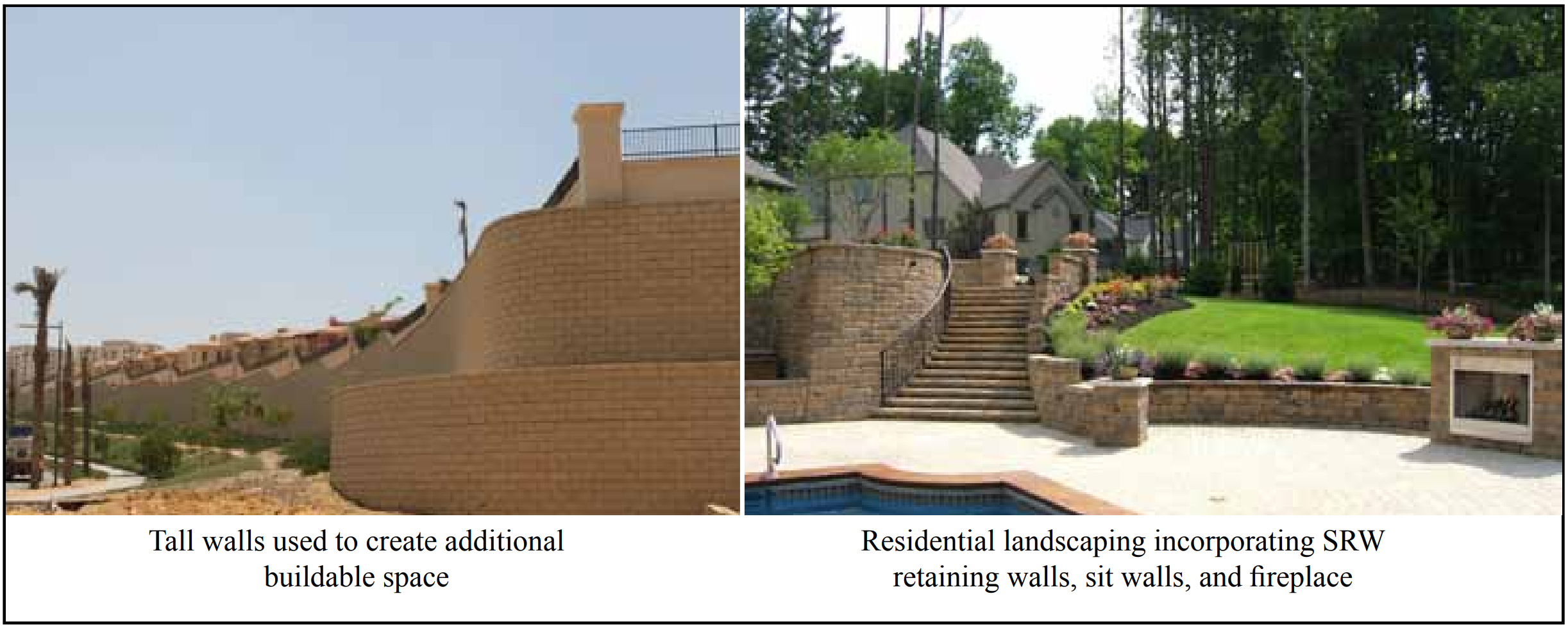
Figure 1—Examples of Segmental Retaining Wall Installations
Materials
ASTM C1372 includes requirements that define acceptable cementitious materials, aggregates, and other constituents used in the manufacture of concrete segmental retaining wall units. These requirements are similar to those included in ASTM C90, Standard Specification for Loadbearing Concrete Masonry Units (ref. 3).
Compressive Strength
Minimum compressive strength requirements for segmental retaining wall units are included in Table 1. Units meeting or exceeding these strengths have demonstrated the integrity needed to resist the structural demands placed on them in normal usage. These demands include impact and vibration during transportation, the weight of the units above them in the wall, nonuniform distribution of loads between units, and the tensile stresses imposed as a result of typical wall settlement.
Segmental retaining wall units will not fail in service due to compressive forces since axial loads are only a result of self-weight. Due to the direct relationship between compressive strength and tensile strength, this minimum requirement is used to ensure overall performance.
Compressive strength testing of full size units is impractical due to the large size and/or unusual shape of some segmental retaining wall units. Therefore, compressive strength of these units is determined from testing coupons cut from the units. The results of tests on these smaller coupons will typically yield lower strengths than if the larger, full-size specimen were tested. The reason for the difference is size and aspect ratio. However, it is important to keep in mind that the compression test is not intended to determine the load-carrying capacity of the unit, since segmental retaining walls are not designed to carry vertical structural loads. Compressive strength is used solely to assess the quality of the concrete.
Because tested strengths are affected by size and shape of the specimen tested, it is important that all retaining wall units be tested using a similar size and shape. ASTM C140/ C140M, Standard Method for Sampling and Testing Concrete Masonry Units and Related Units (ref. 4) requires that specimens cut from full-size units for compression testing must be a coupon with a height to thickness ratio of 2 to 1 before capping and a length to thickness ratio of 4 to 1. The coupon width is to be as close to 2 in. (51 mm) as possible based on the configuration of the unit and the capacity of the testing machine, but not less than 1.5 in. (38 mm). The preferred size is 2 x 4 x 8 in. (51 x 102 x 203 mm) (width x height x length). The coupon height is to be in the same direction as the unit height dimension. If these procedures are followed, the compressive strength of the coupon is considered the strength of the whole unit.
Alignment of the specimen in the compression machine is critical. Care should be taken in capping the test specimen to assure that capping surfaces are perpendicular to the vertical axis of the specimen. Capping needs to be performed in accordance with ASTM C1552, Standard Practice for Capping Concrete Masonry Units, Related Units and Masonry Prisms for Compression Testing (ref. 5).
Saw-cutting is the required method of extracting a test specimen from a full-size unit. Proper equipment and procedures are essential to prevent damaging the test specimen as a result of saw-cutting. Water-cooled, diamond-tipped blades on a masonry table saw are recommended. The blade should ideally have a diameter sufficient enough to make all cuts in a single pass. Manufacturers of the unit (or licensors of proprietary shapes) should be consulted about recommended locations for obtaining the compression specimen.
a Based on oven-dry density of concrete.
Weight Classification
Weight classifications for segmental retaining wall units are defined in Table 1. The three classifications, lightweight, medium weight, and normal weight, are a function of the oven dry density of the concrete. Most segmental retaining wall units fall into the normal weight category.
Absorption
Absorption requirements are also included in Table 1. This value is used to represent the volume of voids in a concrete masonry unit, including voids inside the aggregate itself. The void space is measured by determining the volume of water that can be forced into the unit under the nominal head pressure that results from immersion in a tank of water.
Lightweight aggregates used in the production of lightweight and medium weight units contain voids within the aggregate itself that also fill with water during the immersion test. While reduced voids indicate a desired tightly compacted unit, tightly compacted lightweight and medium weight units will still have higher absorption due to the voids in the aggregates. For this reason the maximum allowable absorption requirements vary according to weight classification.
Similar to compression testing, it generally is not practical to test full-size retaining wall units in absorption tests due to their size and weight. Therefore, ASTM C140/C140M permits the testing of segments saw-cut from full-size units to determine absorption and density. When reduced-size units are used for absorption testing, the reduced-size specimen must have an initial weight of at least 20% of the full-size unit weight. This is intended to ensure that a sufficiently sized specimen is tested in order for the results to be representative of the entire unit.
Absorption limits are typically expressed as mass (weight) of water absorbed per concrete unit volume. This is preferred to expressing by percentage which permits a denser unit to absorb more water than a lighter weight unit.
Testing larger specimens requires particular attention to drying times, because it takes a greater length of time to remove all moisture from larger masses. ASTM C140/C140M requires that specimens be dried for a period of not less than 24 hours at a temperature of at least 221°F (105°C). The 24-hour time period does not start until the oven reaches the specified temperature. When placing larger specimens in an oven, it may take several hours for the oven to reach the prescribed temperature. ASTM C140/C140M then requires that specimen weights be determined every two hours to make sure that the unit is not still losing water weight (maximum weight loss in two hours must be less than 0.2% of the previous specimen weight). This will require 48 hours or more for some specimens. If not adequately dried, reported absorptions will be lower than the actual value.
Permissible Variations in Dimensions
Mortarless systems require consistent unit heights to maintain vertical alignment and level of the wall. For this reason, permissible variation in dimensions is limited to ±⅛ in. (3.2 mm) from the specified standard dimensions. Regarding dimensions, “width” refers to the horizontal dimension of the unit measured perpendicular to the face of the wall. “Height” refers to the vertical dimension of the unit as placed in the wall. “Length” refers to the horizontal dimension of the unit measured parallel to the running length of the wall.
Dimensional tolerance requirements for width are waived for split faced and other architectural surfaces. The surface is intended to be rough to satisfy the architectural features desired and cannot be held to a specific tolerance.
Finish and Appearance
Minor cracks incidental to the usual method of manufacture or minor chipping resulting from customary methods of handling in shipment and delivery are not grounds for rejection. Units used in exposed wall construction are not to show chips or cracks or other imperfections in the exposed face when viewed from a distance of not less that 20 ft (6.1 m) under diffused lighting. In addition, up to five percent of a shipment are permitted to: contain chips on the finished face not larger than 1 in. (25.4 mm) in any dimension; contain cracks on the finished face wider than 0.02 in. (0.5 mm) and longer than 25% of the nominal height of the unit; have dimensions outside the permissible dimensional variations; or be broken.
Freeze-Thaw Durability
Segmental retaining wall units may be used in aggressive freezing and thawing environments. Freeze-thaw damage can occur when units are saturated with water and then undergo temperature cycles that range from above to below the freezing point of water. Freezing and thawing cycles and a constant source of moisture must both be present for potential damage to occur.
Many variations can exist in exposure conditions, any of which may affect the freeze-thaw durability performance of the units. Such variations include: maximum and minimum temperatures, rate of temperature change, duration of temperatures, sunlight exposure, directional facing, source and amount of moisture, chemical exposure, deicing material exposure, and others.
When units are used in applications where freezing and thawing under saturated conditions can occur, ASTM C1372 includes three different methods of satisfying freeze-thaw durability requirements:
Proven field performance,
Five specimens shall have less than 1% weight loss after 100 cycles in water using ASTM C1262 (ref. 6), or
Four of five specimens shall have less than 1.5% weight loss after 150 cycles in water using ASTM C1262.
Segmental retaining wall units in many areas of the country are not exposed to severe exposures. Therefore, the requirements above apply only to “areas where repeated freezing and thawing under saturated conditions occur.”
Freeze-thaw durability tests are conducted in accordance with ASTM C1262, Standard Test Method for Evaluating the Freeze-Thaw Durability of Dry-Cast Segmental Retaining Wall Units and Related Concrete Units, (ref. 6) using water or saline as the test solution. For most applications, tests in water are considered sufficient. If the units will be exposed to deicing salts on a regular basis, consideration should be given to performing the tests in saline. However, no pass/fail criteria has been adopted by ASTM for saline testing.
Compliance
ASTM C1372 also provides guidance regarding compliance. If a sample fails, the manufacturer can remove or cull units from the shipment. Then a new sample is selected by the purchaser from the remaining units of the shipment and tested, which is typically paid for by the manufacturer. If the second sample passes, then the remaining units of the lot being sampled are accepted for use in the project. If the second sample fails; however, the entire lot represented by the sample is rejected.
The specification also provides guidance on responsibility for paying for the tests. Unless otherwise provided for in the contract, the purchaser typically pays for the testing if the units pass the test. However, if the units fail the test, the seller bears the cost of the testing. See SRW-TEC-007-15Sampling and Testing Segmental Retaining Wall Units (ref. 7) for more detailed information on SRW unit sampling, testing, and acceptance.
Standard Specification for Dry Cast Segmental Retaining Wall Units, ASTM C1372-14. ASTM International, 2014.
Standard Specification for Loadbearing Concrete Masonry Units, ASTM C90-14. ASTM International, 2014.
Standard Methods for Sampling and Testing Concrete Masonry Units and Related Units, ASTM C140/C140M-14a. ASTM International, 2014.
Standard Practice for Capping Concrete Masonry Units, Related Units and Masonry Prisms for Compression Testing, ASTM C1552-14. ASTM International, 2014.
Standard Test Method for Evaluating the Freeze-Thaw Durability of Dry-Cast Segmental Retaining Wall Units and Related Concrete Units, ASTM C1262-10. ASTM International, 2010.