Basements allow a building owner to significantly increase usable living, working, or storage space at a relatively low cost. Old perceptions of basements have proven outdated by stateofthe-art waterproofing, improved drainage systems, and natural lighting features such as window wells. Other potential benefits of basements include room for expansion of usable space, increased resale value, and safe haven during storms.
Historically, plain (unreinforced) concrete masonry walls have been used to effectively resist soil loads. Currently, however, reinforced walls are becoming more popular as a way to use thinner walls to resist large backfill pressures. Regardless of whether the wall is plain or reinforced, successful performance of a basement wall relies on quality construction in accordance with the structural design and the project specifications.
Materials
Concrete Masonry Units: Concrete masonry units should comply with Standard Specification for Loadbearing Concrete Masonry Units, ASTM C 90 (ref. 8). Specific colors and textures may be specified to provide a finished interior to the basement. Drywall can also be installed on furring strips, if desired. A rule of thumb for estimating the number of concrete masonry units to order is 113 units for every 100 ft2 (9.3 m2) of wall area. This estimate assumes the use of 3/8 in. (9.5 mm) mortar joints.
Mortar: Mortar serves several important functions in a concrete masonry wall; it bonds the units together, seals joints against air and moisture penetration, and bonds to joint reinforcement, ties, and anchors so that all components perform as a structural element.
Mortar should comply with Standard Specification for Mortar for Unit Masonry, ASTM C 270 (ref. 9). In addition, most building codes require the use of Type M or S mortar for construction of basement walls (refs. 2, 4, 5, 9, 13), because Type M and S mortars provide higher compressive strengths. Table 1 lists mortar proportions.
Typical concrete masonry construction uses about 8.5 ft3 (0.24 m3) of mortar for every 100 ft2 (9.3 m2) of masonry wall area. This figure assumes 3/8 in. (9.5 mm) thick mortar joints, face shell mortar bedding, and a 10% allowance for waste.
Grout: In reinforced concrete masonry construction, grout is used to bond the reinforcement and the masonry together. Grout should conform to Standard Specification for Grout for Masonry, ASTM C 476 (ref. 10), with the proportions listed in Table 2. As an alternative to complying with the proportion requirements in Table 2, grout can be specified to have a minimum compressive strength of 2000 psi (13.8 MPa) at 28 days. Enough water should be added to the grout so that it will have a slump of 8 to 11 in. (203 to 279 mm). The high slump allows the grout to be fluid enough to flow around reinforcing bars and into small voids. This initially high water-to-cement ratio is reduced significantly as the masonry units absorb excess mix water. Thus, grout gains high strengths despite the initially high waterto-cement ratio.
Construction
Prior to laying the first course of masonry, the top of the footing must be cleaned of mud, dirt, ice or other materials which reduce the bond between the mortar and the footing. This can usually be accomplished using brushes or brooms, although excessive oil or dirt may require sand blasting.
Masons typically lay the corners of a basement first so that alignment is easily maintained. This also allows the mason to plan where cuts are necessary for window openings or to fit the building’s plan.
To make up for surface irregularities in the footing, the first course of masonry is set on a mortar bed joint which can range from 1/4 to 3/4 in. (6.4 to 19 mm) in thickness. This initial bed joint should fully bed the first course of masonry units, although mortar should not excessively protrude into cells that will be grouted.
All other mortar joints should be approximately 3/8 in. (9.5 mm) thick and, except for partially grouted masonry, need only provide face shell bedding for the masonry units. In partially grouted construction, webs adjacent to the grouted cells are mortared to restrict grout from flowing into ungrouted cores. Head joints must be filled solidly for a thickness equal to a face shell thickness of the units.
Tooled concave joints provide the greatest resistance to water penetration. On the exterior face of the wall, mortar joints may be cut flush if parging coats are to be applied.
When joint reinforcement is used, it should be placed directly on the block with mortar placed over the reinforcement in the usual method. A mortar cover of at least 5/8 in. (15.9 mm) should be provided between the exterior face of the wall and the joint reinforcement. A mortar cover of 1/2 in. (12.7 mm) is needed on the interior face of the wall. For added safety against corrosion, hot dipped galvanized joint reinforcement is recommended.
See Figures 1-4 for construction details.
Reinforced Masonry: For reinforced masonry construction, the reinforcing bars must be properly located to be fully functional. In most cases, vertical bars are positioned towards the interior face of basement walls to provide the greatest resistance to soil pressures. Bar positioners at the top and bottom of the wall prevent the bars from moving out of position during grouting. A space of at least 1/2 in. (12.7 mm) for coarse grout and 1/4 in. (6.4 mm) for fine grout should be maintained between the bar and the face shell of the block so that grout can flow completely around the reinforcing bars.
As mix water is absorbed by the units, voids can form in the grout. Accordingly, grout must be puddled or consolidated after placement to eliminate these voids and to increase the bond between the grout and the masonry units. Most codes permit puddling of grout when it is placed in lifts less than about 12 in. (305 mm). Lifts over 12 inches (305 mm) should be mechanically consolidated and then reconsolidated after about 3 to 10 minutes.
Surface Bonding: Another method of constructing concrete masonry walls is to dry stack units (without mortar) and then apply surface bonding mortar to both faces of the wall. The surface bonding mortar contains thousands of small glass fibers. When the mortar is applied properly to the required thickness, these fibers, along with the strength of the mortar itself, help produce walls of comparable strength to conventionally laid plain masonry walls. Surface bonded walls offer the benefits of excellent dampproof coatings on each face of the wall and ease of construction.
Dry-stacked walls should be laid in an initial full mortar bed to level the first course. Level coursing is maintained by using a rubbing stone to smooth small protrusions on the block surfaces and by inserting shims every two to four courses.
Water Penetration Resistance: Protecting below grade walls from water entry involves installation of a barrier to water and water vapor. An impervious barrier on the exterior wall surface can prevent moisture entry.
The barrier is part of a comprehensive system to prevent water penetration, which includes proper wall construction and the installation of drains, gutters, and proper grading.
Building codes (refs. 2, 4 , 5, 9, 13) typically require that basement walls be dampproofed for conditions where hydrostatic pressure will not occur, and waterproofed where hydrostatic pressures may exist. Dampproofing is appropriate where groundwater drainage is good, for example where granular backfill and a subsoil drainage system are present. Hydrostatic pressure may exist due to a high water table, or due to poorly draining backfill, such as heavy clay soils. Materials used for waterproofing are generally elastic, allowing them to span small cracks and accommodate minor movements.
When choosing a waterproof or dampproof system, consideration should be given to the degree of resistance to hydrostatic head of water, absorption characteristics, elasticity, stability in moist soil, resistance to mildew and algae, impact or puncture resistance, and abrasion resistance. A complete discussion of waterproofing, dampproofing, and drainage systems is included in TEK 19-03A (ref. 6).
All dampproofing and waterproofing systems should be applied to walls that are clean and free from dirt, mud and other materials which may reduce bond between the coating and the concrete masonry wall.
Draining water away from basement walls significantly reduces the pressure the walls must resist and reduces the possibility of water infiltration into the basement if the waterproofing (or dampproofing) system fails. Perforated pipe has historically proven satisfactory when properly installed. When placed on the exterior side of basement walls, perforated pipes are usually laid in crushed stone to facilitate drainage. To prevent migration of fine soil into the drains, filter fabrics are often placed over the gravel.
Drainage pipes can also be placed beneath the slab and connected into a sump. Pipes through the footing or the wall drain water from the exterior side of the basement wall.
The drainage and waterproofing systems should always be inspected prior to backfilling to ensure they are adequately placed. Any questionable workmanship or materials should be repaired at this stage since repairs are difficult and expensive after backfilling.
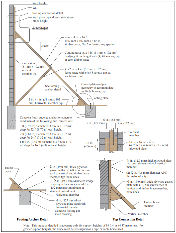
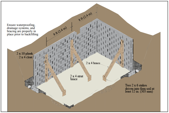
Backfilling: One of the most crucial aspects of basement construction is how and when to properly backfill. Walls should be properly braced or have the first floor in place prior to backfilling. Otherwise, a wall which is designed to be supported at the top may crack or even fail from the large soil pressures. Figure 5 shows one bracing scheme which has been widely used for residential basement walls. More substantial bracing may be required for high walls or large backfill pressures.
The backfill material should be free-draining soil without large stones, construction debris, organic materials, and frozen earth. Saturated soils, especially saturated clays, should generally not be used as backfill materials since wet materials significantly increase the hydrostatic pressure on the walls.
Backfill materials should be placed in several lifts and each layer should be compacted with small mechanical tampers. Care should be taken when placing the backfill materials to avoid damaging the drainage, waterproofing or exterior insulation systems. Sliding boulders and soil down steep slopes should thus be avoided since the high impact loads generated can damage not only the drainage and waterproofing systems but the wall as well. Likewise, heavy equipment should not be operated within about 3 feet (0.9 m) of any basement wall system.
The top 4 to 8 in. (102 to 203 mm) of backfill materials should be low permeability soil so rain water is absorbed into the backfill slowly. Grade should be sloped away from the basement at least 6 in. (152 mm) within 10 feet (3.1 m) of the building. If the ground naturally slopes toward the building, a shallow swale can be installed to redirect runoff.
Construction Tolerances
Specifications for Masonry Structures (ref. 8) specifies tolerances for concrete masonry construction. These tolerances were developed to avoid structurally impairing a wall because of improper placement.
Dimension of elements in cross section or elevation …………………………………….¼ in. (6.4 mm), +½ in. (12.7 mm)
Mortar joint thickness: bed………………………..+⅛ in. (3.2 mm) head………………………………..-¼ in (6.4 mm), +⅜ in. (9.5 mm)
Elements
Variation from level: bed joints………………………………………. ±¼ in. (6.4 mm) in 10 ft (3.1 m), ±½ in. (12.7 mm) max top surface of bearing walls…………………………………………….. ±¼ in.(6.4 mm), +⅜ in.(9.5 mm), ±½ in.(12.7mm) max
Variation from plumb………….±¼ in. (6.4 mm) 10 ft (3.1 m) ………………………………………±⅜ in. (9.5 mm) in 20 ft (6.1 m) ……………………………………………±½ in. (12.7 mm) maximum
True to a line…………………..±¼ in. (6.4 mm) in 10 ft (3.1 m) ………………………………………±⅜ in. (9.5 mm) in 20 ft (6.1 m) ……………………………………………±½ in. (12.7 mm) maximum
Alignment of columns and bearing walls (bottom versus top) ……………………………………………………………..±½ in (12.7 mm)
Location of elements
Indicated in plan……………..±½ in (12.7 mm) in 20 ft (6.1 m) …………………………………………….±¾ in. (19.1 mm) maximum
Indicated in elevation ……………………………………….±¼ in. (6.4 mm) in story height …………………………………………….±¾ in. (19.1 mm) maximum
Insulation: The thermal performance of a masonry wall depends on its R-value as well as the thermal mass of the wall. Rvalue describes the ability to resist heat flow; higher R-values give better insulating performance. The R-value is determined by the size and type of masonry unit, type and amount of insulation, and finish materials. Depending on the particular site conditions and owner’s preference, insulation may be placed on the outside of block walls, in the cores of hollow units, or on the interior of the walls.
Thermal mass describes the ability of materials like concrete masonry to store heat. Masonry walls remain warm or cool long after the heat or air-conditioning has shut off, keeping the interior comfortable. Thermal mass is most effective when insulation is placed on the exterior or in the cores of the block, where the masonry is in direct contact with the interior conditioned air.
Exterior insulated masonry walls typically use rigid board insulation adhered to the soil side of the wall. The insulation requires a protective finish where it is exposed above grade to maintain durability, integrity, and effectiveness.
Concrete masonry cores may be insulated with molded polystyrene inserts, expanded perlite or vermiculite granular fills, or foamed-in-place insulation. Inserts may be placed in the cores of conventional masonry units, or they may be used in block specifically designed to provide higher R-values.
Interior insulation typically consists of insulation installed between furring strips, finished with gypsum wall board or panelling. The insulation may be fibrous batt, rigid board, or fibrous blown-in insulation.
Design Features
Interior Finishes: Split faced, scored, burnished, and fluted block give owners and designers added options to standard block surfaces. Colored units can be used in the entire wall or in sections to achieve specific patterns.
Although construction with staggered vertical mortar joints (running bond) is standard for basement construction, the appearance of continuous vertical mortar joints (stacked bond pattern) can be achieved by using of scored units or reinforced masonry construction.
Natural Lighting: Because of the modular nature of concrete masonry, windows and window wells of a variety of shapes and sizes can be easily accommodated, giving basements warm, natural lighting. For additional protection and privacy, glass blocks can be incorporated in lieu of traditional glass windows.
References
Basement Manual-Design and Construction Using Concrete Masonry, CMU-MAN-002-01, Concrete Masonry & Hardscapes Association, 2001.
BOCA National Building Code. Country Club Hills, IL: Building Officials and Code Administrators International, Inc. (BOCA), 1999.
Building Code Requirements for Masonry Structures, ACI 530-02/ASCE 5-02/TMS 402-02. Reported by the Masonry Standards Joint Committee, 2002.
International Residential Code. Falls Church, VA: International Code Council, 2000.
International Building Code. Falls Church, VA: International Code Council, 2000.
Preventing Water Penetration in Below-Grade Concrete Masonry Walls, TEK 19-03A. Concrete Masonry & Hardscapes Association, 2001.
Seismic Design Provisions for Masonry Structures, TEK 14-18B, Concrete Masonry & Hardscapes Association, 2009.
Specifications for Masonry Structures, ACI 530.1-02/ASCE 6-99/TMS 602-02. Reported by the Masonry Standards Joint Committee, 2002.
Standard Building Code. Birmingham, AL: Southern Building Code Congress International, Inc. (SBCCI), 1999.
Standard Specification for Grout for Masonry, ASTM C 476-01. American Society for Testing and Materials, 2001.
Standard Specification for Load-Bearing Concrete Masonry Units, ASTM C 90-01. American Society for Testing and Materials, 2001.
Standard Specification for Mortar for Unit Masonry, ASTM C 270-00. American Society for Testing and Materials, 2000.
Uniform Building Code. Whittier, CA: International Conference of Building Officials (ICBO), 1997.
When selecting a building enclosure, concrete masonry cavity walls are considered to be one of the best solutions available for all types of buildings. From both an initial cost and life-cycle cost perspective, cavity wall construction is highly regarded as the prime choice in many applications.
Cavity walls typically consist of an inner wythe of concrete masonry units that are tied to an exterior wythe of architectural masonry units. The cavity space between the wythes is normally 2 to 4 ½ in. (51 to 114 mm) wide, easily accommodating rigid board insulation. The two wythes together provide a wall that is highly resistant to wind driven rain, absorbs and reflects sound, provides good thermal performance, and has excellent fire resistance characteristics.
Masonry walls constructed of two or more wythes can technically be classified in one of three ways, depending on how the wythes are designed and detailed. These wall types include composite, noncomposite and veneer assemblies. In noncomposite construction, covered in this TEK, each wythe is connected to the adjacent wythe with metal wall ties, but they are designed such that each wythe individually resists the loads imposed on it. Composite walls are designed so that the wythes act together as a single element to resist structural loads. This requires the masonry wythes to be connected by masonry headers or by a mortar- or grout-filled collar joint and wall ties (see ref. 4). In a veneer wall, the backup wythe is designed as the loadbearing system while the veneer provides a nonloadbearing architectural wall finish that transfers loads to the backup wythe through wall ties (see refs. 5, 6). Although Building Code Requirements for Masonry Structures (ref. 1) defines a cavity wall as a noncomposite masonry wall, the term cavity wall is also commonly used to describe a veneer wall with masonry backup.
This TEK illustrates the design of noncomposite concrete masonry walls based on Building Code Requirements for Masonry Structures (ref. 1), referred to here as the MSJC code. Each wythe of a noncomposite wall system can be designed to accommodate all types of loads, including gravity loads from roofs, walls and floors, as well as lateral loads from wind or earthquakes. The MSJC code design provisions are used to size these masonry walls.
STRUCTURAL DESIGN
The MSJC code includes noncomposite design provisions for both allowable stress design (Chapter 2) and empirical design (Chapter 5). The assumptions and relevant governing equations for each of these design approaches is given in references 2 and 3 respectively.
Concrete masonry cavity walls can be designed as either reinforced or unreinforced walls. For unreinforced design, flexural tensile stresses in masonry are resisted by bond developed between the masonry units and mortar; axial tension is not permitted (ref. 1). If direct axial tension is encountered in a design, reinforcement must be used. In reinforced masonry design, all tension is assumed to be resisted by reinforcement.
Empirical Design
Empirical design can be an expedient approach for typical loadbearing structures subjected to nominal wind loads (basic wind speed ≤ 110 mph, (177 km/h) (MSJC 5.1.2.2) and located in areas of low seismic risk, as it cannot be used for the design of seismic force resisting systems in SDC (Seismic Design Category) B or higher (MSJC 5.1.2.1). Empirical design utilizes prescriptive provisions, outlining criteria such as wall height to thickness ratios, minimum wall thickness and maximum building height.
References 1 and 3 contain maximum length-to-thickness or height-to-thickness ratios for empirically designed walls. When using these ratios for noncomposite multiwythe walls, the total wall thickness is taken as the sum of the nominal thicknesses of each wythe, neglecting the presence of any cavity thickness. Compressive stress is based on the gross cross-sectional area of all wythes, including hollow cells but not including the cavity between the wythes. When floor or roof loads are carried on only one wythe, only the gross cross-sectional area of that wythe is used to check the axial capacity. In addition, these walls must meet the following requirements for wall ties connecting the wythes:
wall ties of wire size W2.8 (3/16 in., MW 18), or metal wire of equivalent stiffness, spaced at a maximum of 24 in. (610 mm) o.c. vertically and 36 in. (914 mm) o.c. horizontally, with at least one wall tie for each 4½ ft² (0.42 m²) of wall area,
walls constructed with hollow units must use rectangular ties,
walls constructed with solid units must use Z-shaped ties with hooks at least 2 in. (51 mm) long,
wall ties may not have drips,
additional ties are required within 12 in. (305 mm) of all openings and must be spaced no more than 3 ft (914 mm) apart around the perimeter of the opening.
Requirements for bonding with joint reinforcement are the same as those for wall ties with the following exceptions: cross wire size may not be smaller than W1.7 (9 gage, MW 11) and the supported wall area per cross wire may not exceed 2⅔ ft² (0.25 m²). In addition, the longitudinal wires must be embedded in mortar.
Allowable Stress Design
Similar to empirical design, MSJC allowable stress design includes prescriptive requirements for bonding wythes of noncomposite walls via wall ties, adjustable ties and joint reinforcement.
For rectangular ties, Z ties (for use with other than hollow units) and ladder or tab-type joint reinforcement, ties or cross wires of joint reinforcement, ties must be placed with a maximum spacing of 36 in. (914 mm) horizontally and 24 in. (610 mm) vertically. The minimum number of ties is one per:
2⅔ ft² (0.25 m²) of wall for wire size W 1.7 (9 gage, MW 11), and
4½ ft² (0.42 m²) of wall for wire size W 2.8 (3/16 in., MW 18).
For adjustable ties, one tie must be provided for each 1.77 ft² (0.16 m²) of wall; maximum horizontal and vertical spacing is 16 in. (406 mm); misalignment of bed joints from one wythe to the other may not exceed 1 ¼ in. (31.8 mm); the maximum clearance between connecting parts of the tie is 1/16 in. (1.6 mm); and pintle ties must have at least two pintle legs of wire size W2.8 (3/16 in., MW 18) (see also Figure 1).
For noncomposite masonry walls, the following additional requirements apply.
Collar joints are not to contain headers, or be filled with mortar or grout.
Gravity loads from supported horizontal members are to be resisted by the wythe nearest the center of the span.
Bending moments about the weak axis of the wall and transverse loads are distributed to each wythe according to relative stiffness. This can be determined by: Wi = WT [EmIi/(EmIi+ EmI0)] Wo = WT [EmI0/(EmIi+ EmI0)]
Loads acting parallel to the wall are resisted by the wythe to which they are applied.
The cavity width between the wythes is limited to 4½ in. (114 mm) unless a detailed wall tie analysis is performed.
The following examples illustrate the use of noncomposite masonry employing empirical and allowable stress design methods. Although there are no specific provisions in MSJC for noncomposite wall design using strength design, strength design could be used provided the same load distribution principles as presented for allowable stress design are employed.
Empirical Design Design Example: Design the top story of a two-story noncomposite double wythe masonry wall system supported on continuous footings. Note that the design of the lower story, though not shown, is performed in the same manner, except that the floor live and dead loads from the upper story are also accounted for.
Given:
unsupported wall height
= 10 ft (3.01 m)
superimposed gravity dead load
= 220 plf (3.2 kN/m)
superimposed gravity live load
= 460 plf (6.7 kN/m)
net superimposed uplift from wind
= 120 plf (1.8 kN/m)
wind pressure
= 24 psf (1,149 Pa)
eccentricity of all gravity loads
= 0
f’m
= 1,500 psi (10.3 MPa)
Em
= 1,350 ksi (9,308 MPa)
Wall lateral support requirement: l/t or h/t < 18, so minimum required wall thickness = h/18 = 10 ft (12 in./ft)/18 = 6.7 in. (169 mm)
Try a 4-in. (102 mm) outer wythe and 6-in. (152 mm) inner wythe (providing a total nominal wall thickness of 10 in. (254 mm)), and check allowable axial compressive stress due to dead and live loads (gravity loads are carried by the inner wythe only):
dead:
roof
220 lb/ft
wythe = 10 ft x 26 psf (ref. 8)
260 lb/ft
live:
roof
460 lb/ft
total load:
940 lb/ft (13.7 kN/m)
Gross area of 6-in. (152-mm) wythe = 67.5 in.²/ft (ref. 7) fa = 940 lb/ft/(67.5 in.²/ft) = 13.9 psi (0.096 MPa) Fa = 75 psi (0.52 MPa) for Type M or S mortar, 70 psi (0.48 MPa) for Type N mortar (ref. 1) fa < Fa (OK for all mortar types)
Per MSJC code section 5.8.3.1, the net uplift on the roof must be resisted by an anchorage system. Use a bond beam at the top of the inner wythe with vertical reinforcement to the foundation to provide this resistance.
ASD Reinforced Design Example: Given:
unsupported wall height
= 18 ft (5.5 m)
wind load, w
= 36 psf (1,724 Pa)
net roof uplift at top of wall
= 400 plf (5.8 kN/m) )
eccentricity of all vertical loads
= 0
f’m
= 1,500 psi (0.0718 MPa )
unit density
= 115 pcf (1,842 kg/m³)
Grade 60 reinforcement
Note: The 36 psf (1,724 Pa) wind load is much higher than is generally applicable when using empirical design.
Design the inside wythe first, as it must resist the uplift in addition to the flexural loads. Try two 6-in. (152 mm) wythes with No. 5 (M #16) reinforcement at 32 in. (813 mm) o.c.
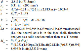
Determine reinforcement needed for uplift at midheight: uplift = 400 lb/ft – 34 lb/ft² (18 ft/2) = 94 lb/ft (1.37 kN/m) (ref. 8) reinforcement needed = [(94 lb/ft)(32 in.)/(12 in./ft)]/[1.333(24,000 psi)] = 0.0078 in.² As available for flexure = 0.31 – 0.0078 = 0.3022 in.² Ms = FsAsjd = 1.333 (24,000 psi) (0.3022 in.²)(0.894)(2.813 in.) = 24,313 lb-in. for 32 in. width = 9,117 lb-in./ft (3,378 N⋅m/m) > 8,996 lb-in./ft (3,333 N⋅m/m), therefore Mm controls
Determine applied moment: Since the wythes are identical, each would carry ½ the lateral load or ½ (36 psf) = 18 psf (124 kPa) Mmax = wl²/8 = (18 psf)(18 ft)²(12 in./ft)/8 = 8,748 lb-in./ft (3,241 N⋅m/m) < 8,996 lb-in./ft (3,333 N⋅m/m) OK
A quick check of the outside wythe shows that the same reinforcement schedule will work for it as well. Therefore, use two 6-in. (152-mm) wythes with No. 5 (M #16) vertical reinforcement at 32 in. (813 mm) o.c.
This wall could be designed using an unreinforced 4-in. (102 mm) outside wythe and a reinforced 8-in. (203-mm) inside wythe, with lateral loads distributed to each wythe according to the uncracked stiffness per MSJC section 1.9.2. Experience has shown, however, that the design would be severely limited by the capacity of the unreinforced outside wythe. Additionally, such a design could be used only in SDC A or B since 4-in. (102 mm) concrete masonry does not have cores large enough to reinforce.
Another alternative would be to design this system treating the 4 in. (102 mm) outer wythe as a nonloadbearing veneer. Designing this wall as a 4-in. (102 mm) veneer with an 8-in. (203 mm) reinforced structural backup wythe would result in No. 5 bars at 16 in. (M #16 at 406 mm) on center. This is the same amount of reinforcement used in the example above (two 6-in. (152 mm) wythes with No. 5 (M #16) at 32 in. (813 mm) on center). However, because the 6-in. (152 mm) units have smaller cores, 30% less grout is required.
The design using two 6-in. (152-mm) reinforced wythes has the following advantages over veneer with structural backup:
no limitation on SDC as when a veneer or an unreinforced outer wythe is used,
no limitation on wind speed as with a veneer,
equal mass on both sides of the wall permitting the use of the prescriptive energy tables for integral insulation, and
the flexibility of using units with different architectural finishes on each side.
NOMENCLATURE
As = effective cross-sectional area of reinforcement, in.²(mm²) b = width of section, in. (mm) d = distance from extreme compression fiber to centroid of tension reinforcement, in. (mm) Em = modulus of elasticity of masonry, psi (MPa) Es = modulus of elasticity of steel, psi (MPa) Fa = allowable compressive stress due to axial load only, psi (kPa) Fb = allowable compressive stress due to flexure only, psi (kPa) Fs = allowable tensile or compressive stress in reinforcement, psi (kPa) Fv = allowable shear stress in masonry, psi (MPa) fa = calculated compressive stress in masonry due to axial load only, psi (kPa) f’m = specified compressive strength of masonry, psi (kPa) h = effective height, in. (mm) fv = calculated shear stress in masonry, psi (MPa) Ii = average moment of inertia of inner wythe, in.4/ft (m4/m) Io = average moment of inertia of outer wythe, in.4/ft (m4/m) j = ratio of distance between centroid of flexural compressive forces and centroid of tensile forces to depth d k = ratio of distance between compression face of wall and neutral axis to depth d l = clear span between supports, in. (mm) M = moment at the section under consideration, in.-lb/ft (N⋅m/m) Mm = flexural capacity (resisting moment) when masonry controls, in.-lb/ft (N⋅m/m) Mmax = maximum moment at the section under consideration, in.-lb/ft (N⋅m/m) Ms = flexural capacity (resisting moment) when reinforcement controls, in.-lb/ft (N⋅m/m) t = nominal thickness of a member, in. (mm) Vmax = maximum shear at the section under consideration, lb/ft (kN/m) Wi = percentage of transverse load on inner wythe Wo = percentage of transverse load on outer wythe WT = total transverse load w = wind pressure, psf (Pa) ρ = reinforcement ratio
REFERENCES
Building Code Requirements for Masonry Structures, ACI 530-02/ASCE 5-02/TMS 402-02. Reported by the Masonry Standards Joint Committee, 2002.
ASD of Concrete Masonry (2012 IBC & 2011 MSJC), TEK 14-07C, Concrete Masonry & Hardscapes Association, 2004.
Empirical Design of Concrete Masonry Walls, TEK 1408B, Concrete Masonry & Hardscapes Association, 2003
Structural Design of Unreinforced Composite Masonry, TEK 16-02B, Concrete Masonry & Hardscapes Association, 2001.
Retaining walls support soil and other materials laterally. That is, retaining walls “retain” earth, keeping it from sliding. Retaining walls must resist overturning and sliding, and the pressure under the toe (front bottom edge of footing) should not exceed the bearing capacity of the soil. Finally, the wall must be strong enough to prevent failure at any point in its height due to the pressure of the retained material. Concrete masonry retaining walls meet these requirements admirably.
Three different types of concrete masonry retaining walls are illustrated in Figure 1. They are the simple unreinforced vertical face gravity retaining wall, the steel reinforced cantilever retaining wall, and the segmental retaining wall. This TEK addresses unreinforced gravity retaining walls only. Each of these retaining wall systems has its advantages, and the choice may depend on a number of factors including aesthetics, constructibility, cost, and suitability for a particular project. The gravity wall is much simpler in design and construction, and can be an effective choice for smaller projects. It is thicker at the base than cantilever and segmental walls, and hence could cost more to construct on larger projects. Gravity retaining walls resist sliding by means of their large mass, whereas cantilever retaining walls are designed to resist sliding by using reinforcement. Because of their large mass, gravity retaining walls may not be appropriate for use on soils with low bearing capacities.
An engineer who is familiar with local conditions can assist in the choice of retain ing wall type. Where especially unfavorable soil conditions occur or where piling is required under a retaining wall, the assistance of an engineer is essential for design and construction.
Figure 1—Concrete Masonry Retaining Walls
DESIGN
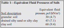
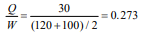
The primary force acting on a retaining wall is the pressure exerted by the retained material at the back of the wall and on the heel of the footing. The magnitude and direction of this pressure depends on the height and shape of the surface and on the nature and properties of the backfill. One common method of estimating backfill pressure is the equivalent fluid pressure method. In this method, it is assumed that the retained earth will act as a fluid in exerting pressure on the wall. Assumed equivalent fluid pressures vary with the type of soil. Representative soil types with their equivalent fluid pressures are shown in Table 1.
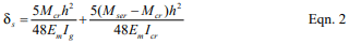
Since the stability of the gravity type retaining wall depends mainly on its weight, the thickness required at its base will increase with height of backfill, or wall height. Uplift pressure at the back of the wall (the heel) is avoided by designing the gravity retaining wall thick enough at the base so that the resultant of all forces (overturning force and vertical loads) falls within a zone called the kern, which is the middle one third of the base. The eccentricity of the resultant force is equal to or less than one-sixth of the base width. When the eccentricity, e, is equal to one-sixth the base width exactly, the maximum footing pressure on the soil at the front edge of the base (toe) will be twice the average pressure on the soil.
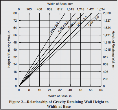
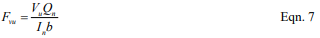
The horizontal force of the retained material causes the overturning moment on the gravity retaining wall. For a given wall height, the required thickness at the base will depend not only on height, but also on the magnitude of the equivalent fluid pressure of the retained soil. The two forces act in opposition; the horizontal force tends to overturn the wall, while the vertical forces tend to stabilize it via gravity. The ratio of wall height to base width will vary with the ratio of vertical pressure to horizontal pressure. More properly, the relationship between thickness of base and wall height can be expressed:
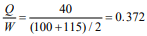
where: H = height of gravity retaining wall, in. (mm) L = width of gravity retaining wall at base, in. (mm) Q = equivalent fluid pressure of retained material acting horizontally as overturning moment, pcf (kg/m³) W = average weight of masonry, soil and other material acting vertically to retain soil, pcf (kg/m³)
This relationship between wall height and base width for gravity retaining walls is shown in Figure 2 for different ratios of horizontal to vertical unit loads. The relationship shown in Figure 2 is employed in the selection of dimensions for gravity retaining walls up to eight ft (1.8 to 2.4 m) high.
Having selected the height-base proportions from Figure 2, the trial design is analyzed for safety against overturning and sliding, bearing pressure on the soil, and flexural and shear stress in the wall.
Figure 2—Relationship of Gravity Retaining Wall Height to Width at Base
CONSTRUCTION AND MATERIALS
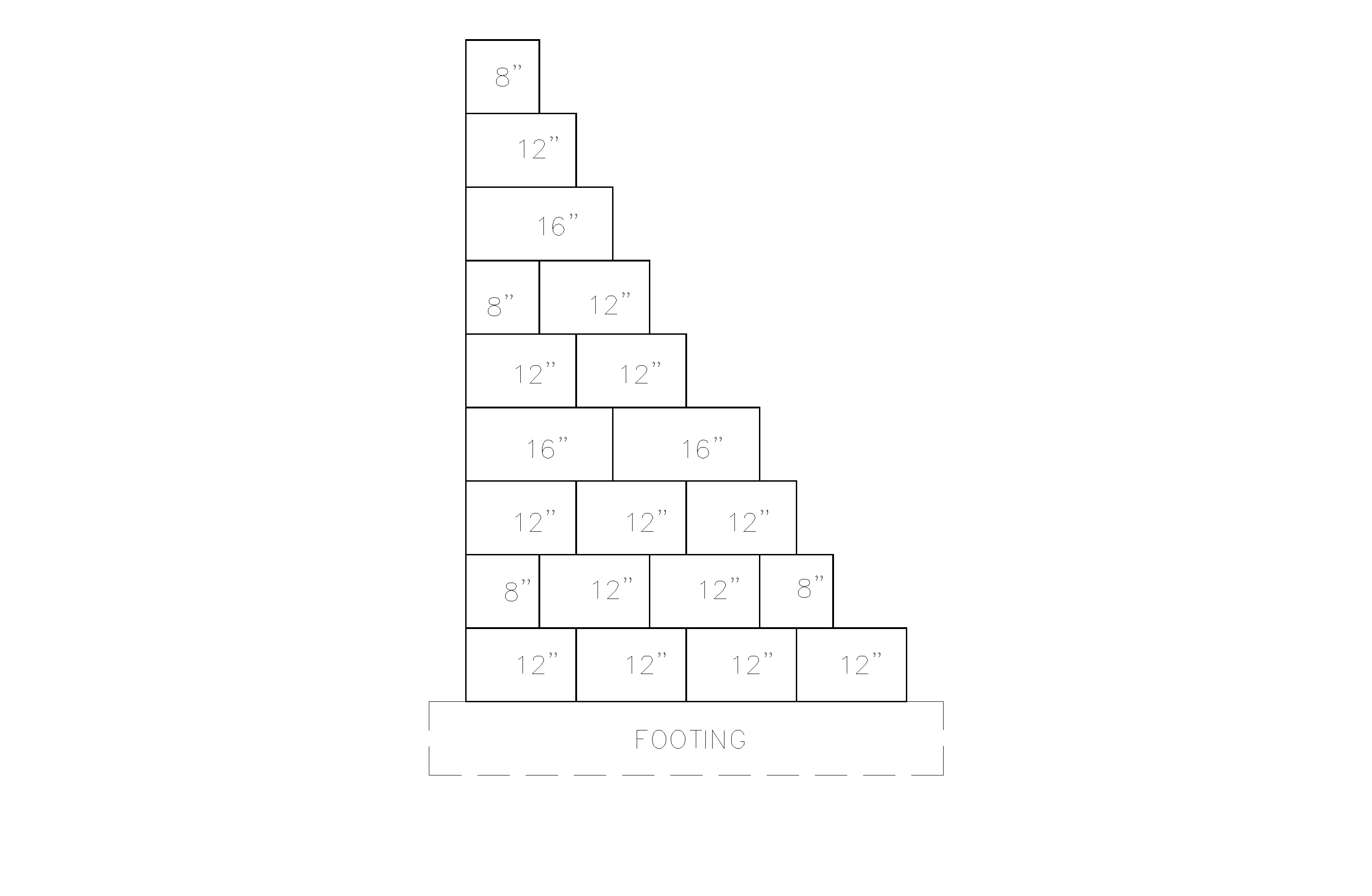
Each course of the retaining wall should be constructed with full-size concrete masonry units, with an overlapping bond pattern between courses, as shown in Figure 3.
Hollow or solid concrete masonry units used in gravity retaining walls should meet the requirements of ASTM C 90 (ref. 2) and preferably have an oven-dry density of 125 lb/ft³ (2002 kg/m³) or more. Cores of hollow units are typically filled to increase the weight of the wall. The fill should be granular in areas subject to freezing. Bond is important to ensure sufficient shear resistance to withstand the pressure exerted by the retained earth. Type M or S mortars complying to ASTM C 270 (ref. 3) are recommended.
Concrete footings should be placed on firm undisturbed soil. In areas where freezing is expected, the base of the footing should be placed below the frost line. If the soil under the footing consists of soft or silty clay, it is usually advisable to place 4 to 6 in. (102 to 152 mm) of well compacted sand or gravel under the footing before pouring the concrete. It is usually not necessary to reinforce the footing.
If heavy equipment is employed for backfilling, it should not be allowed to approach closer to the top of the wall than a distance equal to the wall height. Care should also be taken to avoid large impact forces on the wall as could occur by a large mass of moving earth.
Provision should be made to pre vent water accumulation behind the retaining wall. Accumulated water causes increased pressure, seep age, and in areas subject to frost action, an expansive force of considerable magnitude near the top of the wall. In most instances, weep holes located at 5 to 10 foot (1.5 to 3 m) spacing along the base of the wall are sufficient.
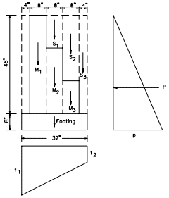
From Figure 2, the base of the wall is 24 in. (610 mm), which can be accomplished using three 8-inch (203 mm) block. Note that the footing weight was not included in the calculation of average unit weight of the materials acting vertically, so that the width determined from Figure 2 would be the width of the masonry wall at its base.
Determine overturning moment: pressure at the base of the wall, p = total soil height x equivalent fluid pressure of soil p = (4.67 ft)(30 pcf) = 140 lb/ft² (6703 Pa) resultant pressure, P = ½ (p)(total soil height) P = ½ (140 lb/ft²)(4.67 ft) = 327 lb/ft (4.8 kN/m)
Determine resisting moment (about the toe): First, determine the weight of each element, then determine the resisting moment of each weight, then sum the resisting moments to determine the total resisting moment.
Element:
Weight
S1
(0.67 ft)(1.33 ft)(100 pcf)
= 89 lb (396 N)
S2
(0.67 ft)(2.67 ft)(100 pcf)
= 179 lb (796 N)
S3
(0.33 ft)(4.0 ft)(100 pcf)
= 132 lb (587 N)
M1
(0.67 ft)(4.0 ft)(120 pcf)
= 322 lb (1432 N)
M2
(0.67 ft)(2.67 ft)(120 pcf)
= 214 lb (952 N)
M3
(0.67 ft)(1.33 ft)(120 pcf)
= 107 lb (476 N)
F
(2.67 ft)(0.67 ft)(150 pcf)
= 268 lb (1192 N)
Element:
Weight, lb (N) x
Arm, ft (m) =
Moment, ft-lb (N-m)
S1
89 (396)
1.33 (0.41)
118.5 (161)
S2
179 (796)
2.00 (0.61)
357.8 (485)
S3
132 (587)
2.50 (0.76)
330.0 (447)
M1
322 (1432)
0.67 (0.20)
215.5 (292)
M2
214 (952)
1.33 (0.41)
285.5 (387)
M3
107 (476)
2.00 (0.61)
213.9 (290)
F
268 (1192)
1.33 (0.41)
356.4 (483)
Total
1311 (5832)
1878 (2546)
Determine the overturning moment about the base, M: M = (P)(⅓ x total height of soil) M = (327 lb/ft)(⅓ x 4.67 ft) = 509 ft-lb/ft (2.28 kN-m/m)
Check safety factors: overturning moment safety factor = 1878/509 = 3.7 3.7 > 2 OK sliding safety factor = (1311 lb)(0.55)/(327 lb/ft) = 2.2 2.2 > 1.5 OK
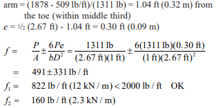
Check pressure on soil:
Since the concrete masonry used in this example is assumed solid or fully grouted, the calculations do not include a check of shear stresses and flexural stresses in the wall. Flexural and shear stresses are checked in the second design example, and it is seen that the magnitudes are very low. Flexural and shear stresses in gravity retaining walls will almost always be of minor importance.
6-foot (1.8 m) high gravity retaining wall equivalent fluid pressure of soil = 40 pcf (7.1 kN/m³) soil weight = 100 pcf (15.7 kN/m³) soil friction coefficient = 0.55 soil bearing capacity = 2000 lb/ft² (0.096 MPa) hollow concrete masonry units, 130 pcf (20.4 kN/m³), units will be filled with sand, resulting in a combined weight of 115 pcf (18.1 kN/m³) f’m = 1500 psi (10.3 MPa)
Type S portland cement-lime mortar concrete footing, 150 pcf (23.6 kN/m³)
First, determine the width of the wall base:
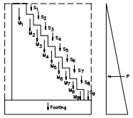
From Figure 2, try a base width of 42 in. (1067 mm), with a footing width of 50 in. (1270 mm)
Determine overturning moment: p = (6.67 ft)(40 pcf) = 267 lb/ft² (0.013 MPa) P = ½ (267 lb/ft²)(6.67 ft) = 890 lb/ft (13 kN/m) M = (890 lb/ft)(⅓ x 6.67 ft) = 1978 ft-lb/ft (8.81 kN-m/m)
Element:
Weight, lb (N) x
Arm, ft (m) =
Moment, ft-lb (N-m)
S1
22 (98)
1.50 (0.46)
33 (45)
S2
44 (196)
1.83 (0.56)
80 (108)
S3
66 (294)
2.17 (0.66)
143 (194)
S4
88 (391)
2.50 (0.76)
220 (298)
S5
110 (489)
2.83 (0.86)
311 (422)
S6
132 (587)
3.17 (0.97)
418 (566)
S7
154 (685)
3.50 (1.07)
539 (731)
S8
176 (783)
3.83 (1.17)
674 (914)
S9
198 (881)
4.17 (1.27)
826 (1120)
M1
690 (3070)
0.83 (0.25)
575 (780)
M2
202 (899)
1.50 (0.46)
303 (411)
M3
177 (787)
1.83 (0.56)
325 (441)
M4
152 (676)
2.17 (0.66)
329 (446)
M5
126 (560)
2.50 (0.76)
316 (428)
M6
101 (449)
2.83 (0.86)
287 (389)
M7
76 (338)
3.17 (0.97)
241 (327)
M8
50 (222)
3.50 (1.07)
177 (240)
M9
25 (111)
3.83 (1.17)
97 (132)
F
419 (1864)
2.08 (0.63)
872 (1182)
Total
3008 (13,380)
6766 (9173)
Check safety factors: overturning moment safety factor = 6766/1978 = 3.4 3.4 > 2 OK sliding safety factor = (3008 lb)(0.55)/(890 lb/ft) = 1.9 1.9 > 1.5 OK
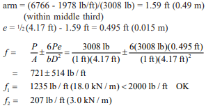
Check pressure on soil: location of P and eccentricity, e:
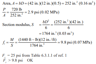
Check flexural stresses: At 6 ft (1.8 m) depth: P = ½ (6 ft)(40 pcf)(6 ft) = 720 lb (3203 N) M = (720 lb)(⅓ x 6 ft) = 1440 ft-lb (1952 N-m)
Assume mortar bed is 50% of gross area:
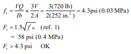
Check shear stresses:
REFERENCES
Building Code Requirements for Masonry Structures, ACI 530-95/ASCE 5-95/TMS 402-95. Reported by the Masonry Standards Joint Committee, 1995.
Standard Specification for Load-Bearing Concrete Masonry Units, ASTM C 90-94. American Society for Testing and Materials, 1994.
Standard Specification for Mortar for Unit Masonry, ASTM C 270-92a. American Society for Testing and Materials, 1992.
Historically, degree of seismic risk and the resulting design loads have been linked to seismic zones, with higher seismic zones associated with higher anticipated ground motion. More recently, design codes and standards (refs. 1, 2, 3) have replaced the use of seismic zones with Seismic Design Categories (SDCs). While seismic zones and design categories share similar concepts, there are also specific considerations that make each unique. The information that follows outlines the procedure for defining a project’s SDC, the permissible design methods that can be used with each SDC, and the prescriptive reinforcement associated with each SDC level.
This TEK is based on the requirements of the 2006 and 2009 editions of the International Building Code (IBC) (refs. 3a, 3b). While the applicable seismic provisions covered have not changed significantly over the last several code cycles, designers and contractors should be aware of several key revisions that have been introduced in recent years.
SEISMIC DESIGN CATEGORIES
SDCs range from SDC A (lowest seismic risk) through SDC F (highest seismic risk). Several factors contribute to defining the seismic design category for a particular project, including:
Maximum earthquake ground motion. Ground acceleration values are obtained from maps published in the IBC (ref. 3) or the ASCE 7 Minimum Design Loads for Buildings and Other Structures (ref. 2).
Local soil profile. Soil profiles are classified as Site Class A (hard rock) through Site Class F (organic or liquefiable soils). When the soil properties are not know in sufficient detail to determine the site class, Site Class D (moderately stiff soil) is assumed.
Use or occupancy hazard of the structure. Each structure is assigned to one of four unique Occupancy Categories corresponding to its use or hazard to life safety. Structures assigned to Occupancy Category I include those with a very low hazard to human life in the event of failure (including many agricultural buildings and minor storage facilities). Structures assigned to Occupancy Category III include those that would present a substantial public hazard including schools, jails, and structures with an occupancy load greater than 5,000. Structures assigned to Occupancy Category IV are designated essential facilities (such as hospitals and fire stations) and structures that contain substantial quantities of hazardous materials. Structures assigned to Occupancy Category II are those not included in any of the other three categories.
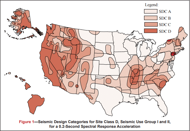
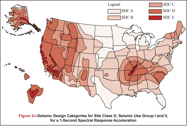
Figures 1 and 2 define the SDC for 0.2 and 1 second spectral response acceleration, respectively. Each figure is based on Site Class D (the default class when the soil profile is not known) and is applicable to structures assigned to Occupancy Categories I, II, and III (buildings other than high hazard exposure structures). Note that if the soil profile is known and is lower than D, a correspondingly lower SDC may be realized.
Structures are assigned to the highest SDC obtained from either Figure 1 or Figure 2. Alternatively, Section 1613.5.6.1 of the 2006 or 2009 IBC (refs. 3a, 3b) permits the SDC to be determined based solely on Figure 1 (0.2 second spectral response acceleration) for relatively short, squat structures (common for masonry buildings) meeting the requirements of that section. Table 1 may be used to apply Figures 1 and 2 to structures assigned to Occupancy Category IV.
Figure 1—Seismic Design Categories for Site Class D, Seismic Use Group I and II, for a 0.2-Second Spectral Response Acceleration
Figure 2—Seismic Design Categories for Site Class D, Seismic Use Group I and II, for a 1-Second Spectral Response Acceleration
Table 1—SDC for Structures Assigned to Occupancy Category IV
DESIGN LIMITATIONS
Based on the assigned SDC, limitations are placed on the design methodology that is permitted to be used for the design of the seismic force-resisting system (i.e., the masonry shear walls).
Designers have the option of using several design methods for masonry structures: empirical design (ref. 4); allowable stress design (ref. 5); strength design (ref. 6); or prestressed masonry design (ref. 7), each of which is based on the provisions contained in the Masonry Standards Joint Committee Building Code Requirements for Masonry Structures (MSJC) (ref. 1). There are, however, restrictions placed on the use of both empirical design and unreinforced masonry, neither of which considers reinforcement, if present, as contributing to the structure’s strength or ductility. Table 2 summarizes the design procedures that may be used for each SDC.
Similarly, as the seismic risk/hazard increases, codes require more reinforcement to be incorporated into the structure. This reinforcement is prescriptively required as a minimum and is not a function of any level of determined loading on the structure. That is, design loads may require a specific reinforcement schedule to safely resist applied loads, which cannot be less than the minimum prescriptive seismic reinforcement triggered by the assigned SDC. For convenience, each level of prescriptive seismic reinforcement is given a unique name as summarized in Table 3.
The following discussion reviews in detail the seismic design requirements for loadbearing and nonloadbearing concrete masonry assemblies as required under the 2006 and 2009 IBC, which in turn reference the 2005 and 2008 MSJC, respectively. While many of the seismic design and detailing requirements between these two code editions are similar, there are unique differences that need to be considered when using one set of provisions over the other. The information presented covers the seismic design and detailing requirements for all concrete masonry construction with the exception of concrete masonry veneers, which is addressed in TEK 03-06C, Concrete Masonry Veneers (ref. 8).
The requirements listed below for each SDC and shear wall type are cumulative. That is, masonry assemblies in structures assigned to SDC B must meet the requirements for SDC A as well as those for SDC B. Buildings assigned to SDC C must meet the requirements for Categories A, B and C, and so on.
Table 2—Permitted Design Procedures for Elements Participating in the Lateral Force-Resisting System
Table 3—Permitted Shear Wall Types for Seismic Design Categories
2006 IBC SEISMIC DESIGN AND DETAILING REQUIREMENTS
The seismic design and detailing provisions for masonry are invoked through Section 2106 of the IBC (ref. 3a), which in turn references the 2005 MSJC (ref. 1a). The IBC provisions detail a series of modifications and additions to the seismic requirements contained in the MSJC, which include:
IBC Section 2106.1 requires all masonry walls, regardless of SDC, not designed as part of the seismic force-resisting system (partition and nonloadbearing walls, eg.) to be structurally isolated, so that in-plane loads are not inadvertently imparted to them. The MSJC, conversely, requires isolation of such elements only for SDC C and higher.
IBC Section 2106.1.1 outlines minimum prescriptive detailing requirements for three prestressed masonry shear wall types: ordinary plain, intermediate, and special prestressed masonry shear walls. While the MSJC contains general design requirements for prestressed masonry systems, it does not contain prescriptive seismic requirements applicable to this design approach.
Anchorage requirements are addressed by Section 2106.2 of the IBC. Although analogous requirements are included in MSJC Section 1.14.3.3, the MSJC requirements are based on antiquated design loads that are no longer compatible with those of the IBC.
For structures assigned to SDC C and higher that include columns, pilasters and beams, and that are part of the seismic force-resisting system and support discontinuous masonry walls, IBC Section 2106.4.1 requires these elements to have a minimum transverse reinforcement ratio of 0.0015, with a maximum transverse reinforcement spacing of one-fourth the least nominal dimension for columns and pilasters and one-half the nominal depth for beams.
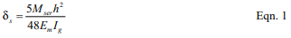
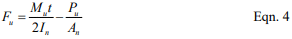
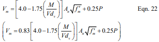
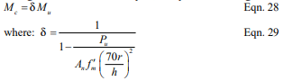
For structures assigned to SDC D and higher, IBC Section 2106.5 includes modifications that are an indirect means of attempting to increase the flexural ductility of elements that are part of the seismic force-resisting system. For elements designed by allowable stress design provisions (MSJC Chapter 2), in-plane shear and diagonal tension stresses are required to be increased by 50 percent. For elements designed by strength design provisions (MSJC Chapter 3) that are controlled by flexural limit states, the nominal shear strength at the base of a masonry shear wall is limited to the strength provided by the horizontal shear reinforcement in accordance with Eqn. 1.
Due to a shear capacity check in MSJC Section 3.1.3 that requires the nominal shear strength of a shear wall to equal or exceed the shear corresponding to the development of approximately 156% of the nominal flexural strength, Equation 1 controls except in cases where the nominal shear strength equals or exceeds 250% of the required shear strength. For such cases, the nominal shear strength is determined as a combination of the shear strength provided by the masonry and the shear reinforcement.
2005 MSJC Seismic Design and Detailing Requirements
The majority of the prescriptive seismic design and detailing requirements for masonry assemblies are invoked by reference to Section 1.14 of the 2005 MSJC. The following summarizes these requirements as they apply to concrete masonry construction.
Masonry Shear Wall Types
In addition to the prestressed masonry shear walls outlined by the IBC, the MSJC includes detailing requirements for six different shear wall options. A summary of these shear wall types follows. Table 3 summarizes the SDCs where each shear wall type may be used.
Empirically Designed Masonry Shear Walls—Masonry shear walls designed by the empirical design method (MSJC Chapter 5). Empirically designed masonry shear walls do not account for the contribution of reinforcement (if present) in determining the strength of the system.
Ordinary Plain (Unreinforced) Masonry Shear Walls—Ordinary plain masonry shear walls are designed as unreinforced elements, and as such rely entirely on the masonry to carry and distribute the anticipated loads. These shear walls do not require any prescriptive reinforcement. As such, they are limited to SDCs A and B.
Detailed Plain (Unreinforced) Masonry Shear Walls—Detailed plain masonry shear walls are also designed as unreinforced elements, however some prescriptive reinforcement is mandated by the MSJC to help ensure a minimum level of inelastic deformation capacity and energy dissipation in the event of an earthquake. As the anticipated seismic risk increases (which corresponds to higher SDCs), the amount of prescriptive reinforcement also increases. The minimum prescriptive reinforcement for detailed plain masonry shear walls is shown in Figure 3.
Ordinary Reinforced Masonry Shear Walls—Ordinary reinforced masonry shear walls, which are designed using reinforced masonry procedures, rely on the reinforcement to carry and distribute anticipated tensile stresses, and on the masonry to carry compressive stresses. Although such walls contain some reinforcement, the MSJC also mandates prescriptive reinforcement to ensure a minimum level of performance during a design level earthquake. The reinforcement required by design may also serve as the prescriptive reinforcement. The minimum prescriptive vertical and horizontal reinforcement requirements are identical to those for detailed plain masonry shear walls (see Figure 3).
Intermediate Reinforced Masonry Shear Walls—Intermediate reinforced masonry shear walls are designed using reinforced masonry design procedures. Intermediate reinforced shear wall reinforcement requirements differ from those for ordinary reinforced in that the maximum spacing of vertical reinforcement is reduced from 120 in. (3,048 mm) to 48 in. (1,219 mm) (see Figure 4).
Special Reinforced Masonry Shear Walls—Prescriptive reinforcement for special reinforced masonry shear walls must comply with the requirements for intermediate reinforced masonry shear walls and the following (see also Figure 5):
The sum of the cross-sectional area of horizontal and vertical reinforcement must be at least 0.002 times the gross cross- sectional wall area.
The cross-sectional reinforcement area in each direction must be at least 0.0007 times the gross cross-sectional wall area.
The vertical and horizontal reinforcement must be uniformly distributed.
The minimum cross-sectional area of vertical reinforcement must be one-third of the required horizontal reinforcement.
All horizontal reinforcement must be anchored around the vertical reinforcement with a standard hook.
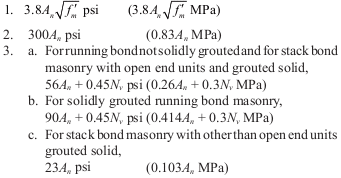
The following additional requirements pertain to stack bond masonry shear walls assigned to SDC D, E or F. These walls must be constructed using fully grouted open-end units, fully grouted hollow units laid with full head joints, or solid units. The maximum reinforcement spacing for stack bond masonry shear walls assigned to SDC D is 24 in. (610 mm). For those assigned to SDC E or F, the cross-sectional area of horizontal reinforcement must be at least 0.0025 times the gross cross-sectional area of the masonry, and it must be spaced at 16 in. (406 mm) o.c., maximum.
Prescriptive Seismic Detailing for Nonloadbearing Elements
When incorporated into structures assigned to SDC C, D, E or F, masonry partition walls and other nonloadbearing masonry elements (i.e., those not designed to resist loads other than those induced by their own mass) must be isolated from the lateral force-resisting system. This helps ensure that forces are not inadvertently transferred from the structural to the nonstructural system. Nonstructural elements, such as partition walls, assigned to SDC C and above must be reinforced in either the horizontal or vertical direction (see Figure 6).
Figure 3—Prescriptive Seismic Detailing for Detailed Plain (Unreinforced) Masonry Shear Walls and for Ordinary Reinforced Masonry Shear Walls
Figure 4—Prescriptive Seismic Detailing for Intermediate Reinforced Masonry Shear Walls
Figure 5—Prescriptive Seismic Detailing for Special Reinforced Masonry Shear Walls
Figure 6—Reinforcement Options for Nonloadbearing Elements in SDC C and Higher
2009 IBC SEISMIC DESIGN AND DETAILING REQUIREMENTS
Unlike the 2006 IBC, the 2009 edition, which references the 2008 MSJC, contains no modifications to the seismic design and detailing provisions of the referenced standard. A summary of the substantive differences between the seismic design and detailing provisions of the 2005 and 2008 editions of the MSJC follows.
2008 MSJC Seismic Design and Detailing Requirements
The 2008 MSJC includes a comprehensive reorganization of the seismic design and detailing requirements intended to clarify the scope and intent of these provisions. In addition to the reorganization, several substantive changes applicable to concrete masonry construction have been incorporated, and these are detailed below. The prescriptive seismic detailing requirements for masonry shear walls remains substantially the same as under the 2005 MSJC and 2006 IBC.
Participating versus Nonparticipating Members—Elements of a masonry structure must now be explicitly classified either as participating in the seismic force-resisting system (for example, shear walls) or as nonparticipating members (for example, nonloadbearing partition walls). Elements designated as shear walls must satisfy the requirements for one of the designated shear wall types. Nonparticipating members must be appropriately isolated to prevent their inadvertent structural participation. This provision is similar in intent to the 2006 IBC requirement to isolate partition walls in SDC A and higher.
Connections—In previous editions of the MSJC, a minimum unfactored (service level) connection design force of 200 lb/ ft (2,919 N/m) was prescribed for all masonry shear wall assemblies except ordinary plain (unreinforced) masonry shear walls. In the 2008 MSJC, this minimum design load has been removed and replaced with a reference to the minimum loads prescribed by the adopted model building code. When the adopted model building code does not prescribe such loads, the requirements of ASCE 7 are to be used, which require a factored design force (strength level) of 280 lb/ft (4,087 N/m).
Story Drift—Due to the inherent stiffness of masonry structures, designers are no longer required to check the displacement of one story relative to adjacent stories for most masonry systems, simplifying the design process. Shear wall systems that are not exempted from checks for story drift include prestressed masonry shear walls and special reinforced masonry shear walls.
Stack Bond Prescriptive Detailing—Special reinforced masonry shear walls constructed of masonry laid in stack bond must now have a minimum area of horizontal reinforcement of 0.0015 times the gross cross-sectional wall area. This is an increase from the 0.0007 required in such walls in structures assigned to SDC D, and is a decrease from the 0.0025 required in such walls in structures assigned to SDC E and F by earlier editions of the MSJC.
Shear Capacity Check—In the 2005 MSJC, all masonry elements (both reinforced and unreinforced) designed by the strength design method were required to have a design shear strength exceeding the shear corresponding to the development of 125 percent of the nominal flexural strength, but need not be greater than 2.5 times the required shear strength. Because this provision is related primarily to the seismic performance of masonry structures, the 2008 MSJC requires it only for special reinforced masonry shear walls. Similarly, when designing special reinforced masonry shear walls by the allowable stress design method, the shear and diagonal tension stresses resulting from in-plane seismic forces are required to be increased by a factor of 1.5. Each of these checks is intended to increase flexural ductility while decreasing the potential for brittle shear failure.
Stiffness Distribution—In Chapter 1 of the 2008 MSJC, prescriptive seismic detailing requirements for masonry shear walls are related to an implicit level of inelastic ductile capacity. Because these detailing provisions apply primarily to shear walls, which in turn provide the principal lateral force-resistance mechanism for earthquake loads, the 2008 MSJC requires that the seismic lateral force-resisting system consist mainly of shear wall elements. At each story, and along each line of lateral resistance within a story, at least 80 percent of the lateral stiffness is required to be provided by shear walls. This requirement is intended to ensure that other elements, such as masonry piers and columns, do not contribute a significant amount of lateral stiffness to the system, which might in turn inadvertently change the seismic load distribution from that assumed in design. The 2008 MSJC does permit, however, the unlimited use of non-shear wall elements such as piers and columns provided that design seismic loads are determined using a seismic response modification factor, R, of 1.5 or less, consistent with the assumption of essentially elastic response to the design earthquake. In previous editions of the MSJC, these requirements were imposed only for masonry designed by the strength design method. In the 2008 MSJC, this requirement applies to all structures assigned to SDC C or higher.
Support of Discontinuous Elements—New to the 2008 MSJC, which was previously found in the 2006 IBC provisions, are the prescriptive detailing requirements for masonry columns, pilasters, and beams supporting discontinuous stiff elements that are part of the seismic force-resisting system. Such elements can impose actions from gravity loads, and also from seismic overturning, and therefore require that the columns, pilasters and beams supporting them have stricter prescriptive reinforcement requirements. These requirements apply only to structures assigned to SDC C and higher.
System Response Factors for Prestressed Masonry—In determining seismic base shear and story drift for structures whose seismic lateral force-resisting system consists of prestressed masonry shear walls, the value of the response modification coefficient, R, and of the deflection amplification factor, Cd, are required to be taken equal to those used for ordinary plain (unreinforced) masonry shear walls. The requirement previously existed as a recommendation in the MSJC Code Commentary. These values, as they apply to all types of masonry shear walls, are summarized in Table 4.
Table 4—Seismic Design Coefficients and Factors for Masonry Bearing Wall Systems
REFERENCES
Building Code Requirements for Masonry Structures, Reported by the Masonry Standards Joint Committee.
2005 Edition: ACI 530-05/ASCE 5-05/TMS 402-05
2008 Edition: TMS 402-08/ACI 530-08/ASCE 5-08
Minimum Design Loads for Buildings and Other Structures, ASCE 7-05. American Society of Civil Engineers, 2005.
International Building Code. International Code Council.
2006 Edition
2009 Edition
Empirical Design of Concrete Masonry Walls, TEK 14-08B. Concrete Masonry & Hardscapes Association, 2008.
ASD of Concrete Masonry (2012 IBC & 2011 MSJC), TEK 14-07C, Concrete Masonry & Hardscapes Association, 2004.
Strength Design of Concrete Masonry, TEK 14-04B. Concrete Masonry & Hardscapes Association, 2008.
Empirical design is a procedure of proportioning and sizing unreinforced masonry elements based on known historical performance for a given application. Empirical provisions preceded the development of engineered masonry design, and can be traced back several centuries. This approach to design is based on historical experience in lieu of analytical methods. It has proven to be an expedient design method for typical loadbearing structures subjected to relatively small wind loads and located in areas of low seismic risk. Empirical design has also been used extensively for the design of exterior curtain walls and interior partitions.
Using empirical design, vertical and lateral load resistance is governed by prescriptive criteria which include wall height to thickness ratios, shear wall length and spacing, minimum wall thickness, maximum building height, and other criteria, which have proven to be effective through years of experience.
This TEK is based on the provisions of Section 2109 of the International Building Code (IBC) (ref. 1). These empirical design requirements do not apply to other design methods such as allowable stress or limit states design. For empirical design of foundation walls, see TEK 15-01B, Allowable Stress Design of Concrete Masonry Foundation Walls (ref. 2)
APPLICABILITY OF EMPIRICAL DESIGN
The IBC allows elements of masonry structures to be designed by empirical methods when assigned to Seismic Design Category (SDC) A, B or C, subject to additional restrictions described below. When empirically designed elements are part of the seismic lateral force resisting system, however, their use is limited to SDC A.
Empirical design has primarily been used with masonry laid in running bond. When laid in stack bond, the IBC requires a minimum amount of horizontal reinforcement (0.003 times the wall’s vertical cross-sectional area and spaced not more than 48 in. (1,219 mm) apart).
In addition, buildings that rely on empirically designed masonry walls for lateral load resistance are allowed up to 35 ft (10.7 m) in height.
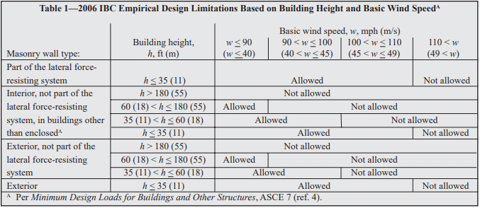
The 2003 IBC restricts empirical design to locations where the basic wind speed (three-second gust, not fastest mile) is less than or equal to 110 mph (79 m/s), as defined in Minimum Design Loads for Buildings and Other Structures, ASCE 7 (ref. 3). A wind speed of this velocity generally applies along the East and Gulf coasts of the United States.
The 2006 IBC further refines the empirical design limitations. Whereas with the 2003 IBC, the designer need only check the SDC and basic wind speed, with the 2006 IBC, to use empirical design the designer must check:
SDC,
basic wind speed,
building height, and
location of gravity loads resultant.
The limitations based on SDC are the same as in the 2003 IBC, described above. Building height and basic wind speed conditions where empirical design is permitted under the 2006 IBC are summarized in Table 1.
The 2006 IBC also requires the resultant of gravity loads to fall within the kern of the masonry element, to avoid imparting tension to the element. This area is defined as: within the center third of the wall thickness, or, for foundation piers, within the central area bounded by lines at one-third of each cross-sectional dimension of the pier.
Table 1—2006 IBC Empirical Design Limitations Based on Building Height and Basic Wind Speed
DESIGN PROVISIONS
Minimum Wall Thickness
Empirically designed (unreinforced) bearing walls of one story buildings must be at least 6 in. (152 mm) thick. For buildings more than one story high, walls must be at least 8 in. (203 mm) thick. The minimum thickness for unreinforced masonry shear walls and for masonry foundation walls is also 8 in. (203 mm). Note that the 2003 IBC allows shear walls of one-story buildings to have a minimum thickness of 6 in. (152 mm).
Lateral Support
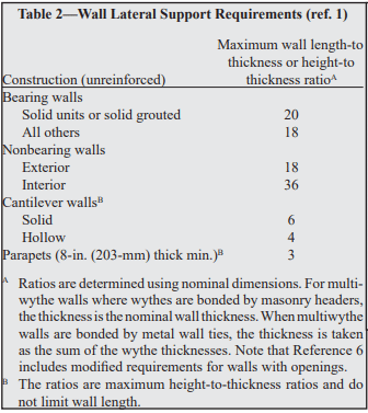
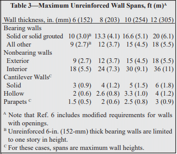
Lateral support for walls can be provided in the horizontal direction by cross walls, pilasters, buttresses and structural frame members, or in the vertical direction by floor diaphragms, roof diaphragms and structural frame members, as illustrated in Figure 1. For empirically designed walls, such support must be provided at the maximum intervals given in Tables 2 and 3. Note that the span limitations apply to only one direction; that is, the span in one direction may be unlimited as long as the span in the other direction meets the requirements of Tables 2 or 3.
Figure 1—Lateral Support of Empirically Designed (Unreinforced) Concrete Masonry Walls
Table 2—Wall Lateral Support Requirements (ref. 1)
Table 3—Maximum Unreinforced Wall Spans, ft (m)
Allowable Stresses
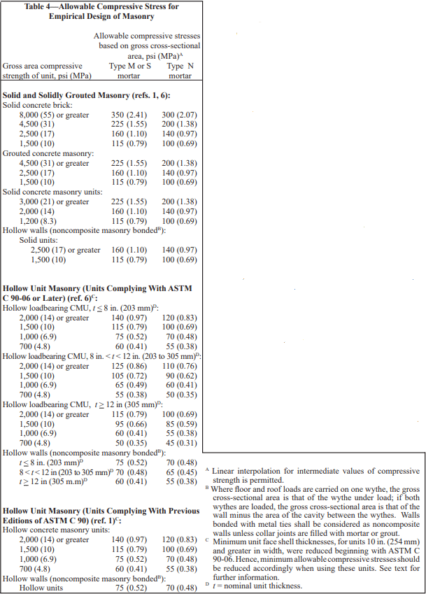
Allowable stresses in empirically designed masonry due to building code prescribed vertical (gravity) dead and live loads (excluding wind or seismic) are given in Table 4.
Table 4 includes two sets of compressive stresses for hollow concrete masonry units (CMU). The first set, titled “Hollow Unit Masonry (Units Complying With ASTM C 90- 06 or Later)” apply to most CMU currently available. The 2006 edition of the CMU specification, Standard Specification for Loadbearing Concrete Masonry Units, ASTM C 90 (ref. 7), included slightly reduced minimum face shell thickness requirements for CMU 10 in. (254 mm) and greater in width. These smaller face shells require a corresponding adjustment to the allowable compressive stresses. The values currently published in the 2006 IBC (“Hollow Unit Masonry (Units Complying With Previous Editions of ASTM C 90)” in Table 4), apply to the previous face shell thicknesses, and should only be used if the CMU to be used have the thicker face shells listed in previous editions of ASTM C 90. This distinction is not applicable to masonry that will be solidly grouted.
Calculated compressive stresses for both single and multiwythe walls are determined by dividing the design load by the gross cross-sectional area of the wall, excluding areas of openings, chases or recesses. The area is based on the specified dimensions of masonry, rather than on nominal dimensions. In multiwythe walls, the allowable stress is determined by the weakest combination of units and mortar shown in Table 4.
In addition, the commentary to Building Code Requirements for Masonry Structures (refs. 6, 8) contains additional guidance for concentrated loads. According to the commentary, when concentrated loads act on empirically designed masonry, the course immediately under the point of bearing should be a solid unit or be filled solid with mortar or grout. Further, when the concentrated load acts on the full wall thickness, the allowable stresses under the load may be increased by 25 percent. The allowable stresses may be increased by 50 percent when concentrated loads act on concentrically placed bearing plates that are greater than one-half but less than the full area.
Table 4—Allowable Compressive Stress for Empirical Design of Masonry
Anchorage for Lateral Support
Where empirically designed masonry walls depend on cross walls, roof diaphragms, floor diaphragms or structural frames for lateral support, it is essential that the walls be properly anchored so that the imposed loads can be transmitted from the wall to the supporting element. Minimum anchorage requirements for intersecting walls and for floor and roof diaphragms are shown in Figures 2 and 3, respectively.
Masonry walls are required to be anchored to structural frames that provide lateral support by ½ in. (13 mm) diameter bolts spaced at a maximum of 4 ft (1.2 m), or with other bolts and spacings that provide equivalent anchorage. The bolts must be embedded a minimum of 4 in. (102 mm) into the masonry.
In addition, the 2006 IBC requires the designer to check the roof loading for net uplift and, where net uplift occurs, to design the anchorage system to entirely resist the uplift.
Figure 2—Empirical Anchorage Requirements for Lateral Support of Intersecting Masonry Walls
Figure 3—Empirical Anchorage Requirements for Floor and Roof Diaphragms
Shear Walls
Where the structure depends on masonry walls for lateral stability against wind or earthquake forces, shear walls must be provided parallel to the direction of the lateral forces as well as in a perpendicular plane, for stability.
Requirements for empirically designed masonry shear walls are shown in Figure 4.
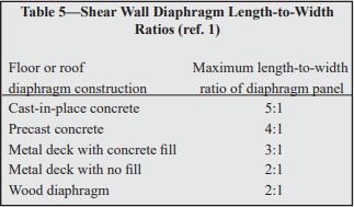
Shear wall spacing is determined empirically by the length-to-width aspect ratio of the diaphragms that transfer lateral forces to the shear walls, as listed in Table 5. In addition, roofs must be designed and constructed in a manner such that they will not impose thrust perpendicular to the shear walls to which they are attached.
The height of empirically designed shear walls is not permitted to exceed 35 ft (10.7 m). The minimum nominal thickness of shear walls is 8 in. (203 mm), except under the 2003 IBC, which allows shear walls of one-story buildings to have a minimum thickness of 6 in. (152 mm).
Figure 4—Empirically Designed Shear Wall Requirements
Wythes of multiwythe masonry walls are required to be bonded together. Bonding can be achieved using masonry headers, metal wall ties, or prefabricated joint reinforcement, as illustrated in Figure 5. Various empirical requirements for each of these bonding methods are given below.
Bonding of solid unit walls with masonry headers. Where masonry headers are used to bond wythes of solid masonry construction, at least 4 percent of the wall surface of each face must be composed of headers, which must extend at least 3 in. (76 mm) into the backing. The distance between adjacent full-length headers may not exceed 24 in. (610 mm) in either the horizontal or vertical direction. In walls where a single header does not extend through the wall, headers from opposite sides must overlap at least 3 in. (76 mm), or headers from opposite sides must be covered with another header course which overlaps the header below by at least 3 in. (76 mm).
Bonding of hollow unit walls with masonry headers. Where two or more hollow units are used to make up the thickness of a wall, the stretcher courses must be bonded at vertical intervals not exceeding 34 in. (864 mm) by lapping at least 3 in. (76 mm) over the unit below, or by lapping at vertical intervals not exceeding 17 in. (432 mm) with units that are at least 50 percent greater in thickness than the units below.
Bonding with metal wall ties (other than adjustable ties). Wire size W2.8 (MW18) wall ties, or metal wire of equivalent stiffness, may be used to bond wythes. Each 4½ ft² (0.42 m²) of wall surface must have at least one tie. Ties must be spaced a maximum of 24 in. (610 mm) vertically and 36 in. (914 mm) horizontally. Hollow masonry walls must use rectangular wall ties for bonding. In other walls, ends of ties must be bent to 90° angles to provide hooks no less than 2 in. (51 mm) long. Additional bonding ties are required at all openings, and must be spaced a maximum of 3 ft (914 mm) apart around the perimeter and located within 12 in. (305 mm) of the opening. Note that wall ties may not include drips, and that corrugated ties may not be used.
Bonding with adjustable ties. Adjustable ties must be spaced such that there is one tie for each 1.77 ft² (0.164 m²) of wall area, with maximum horizontal and vertical spacings of 16 in. (406 mm). The ties must have a maximum clearance between connecting parts of 1/16 in. (1.6 mm), and, when pintle legs are used, at least two legs with a minimum wire size of W2.8 (MW18). The bed joints of the two wythes may have a maximum vertical offset of no more than 1¼ in. (32 mm). (See Reference 9 for an illustration of these requirements.)
Bonding with prefabricated joint reinforcement. Where adjacent wythes of masonry are bonded with prefabricated joint reinforcement, there must be at least one cross wire serving as a tie for each 2⅔ ft² (0.25 m²) of wall area. The joint reinforcement must be spaced 24 in. (610 mm) or closer vertically. Cross wires on prefabricated joint reinforcement must be at least wire size W1.7 (MW11) and shall be without drips. The longitudinal wires must be embedded in the mortar.
Figure 5—Types of Bonding
Change in Wall Thickness
Whenever wall thickness is decreased, at least one course of solid masonry, or special units or other construction, must be placed under the thinner section to ensure load transfer to the thicker section below.
Miscellaneous Empirical Requirements
Following are additional empirical requirements in Building Code Requirements for Masonry Structures. Although not included explicitly in IBC Section 2109, the IBC includes a direct reference to Building Code Requirements for Masonry Structures.
Chases and Recesses Masonry directly above chases or recesses wider than 12 in. (305 mm) must be supported on lintels.
Lintels Lintels are designed as reinforced beams, using either the allowable stress design or the strength design provisions of Building Code Requirements for Masonry Structures. End bearing must be at least 4 in. (102 mm), although 8 in. (203 mm) is typical.
Support on Wood Empirically designed masonry is not permitted to be supported by wood girders or other forms of wood construction, due to expected deformations in wood from deflection and moisture, causing distress in the masonry, and due to potential safety implications in the event of fire.
Corbelling When corbels are not designed using allowable stress design or strength design, they may be detailed using the empirical requirements shown in Figure 6. Only solid or solidly grouted masonry units may be used for corbelling.
Figure 6—Prescriptive Requirements for Corbelling
EMPIRICALLY DESIGNED PARTITION WALLS
In many cases, the building structure is designed using traditional engineered methods, such as strength design or allowable stress design, but the interior nonloadbearing masonry walls are empirically designed. In these cases, the partition walls are supported according to the provisions listed in Tables 2 and 3, but it is important that the support conditions provide isolation between the partition walls and the building’s structural elements to prevent the building loads from being transferred into the partition. The anchor, or other support, must provide the required lateral support for the partition wall while also allowing for differential movement. This is in contrast to the “Anchorage for Lateral Support” section, which details anchorage requirements to help ensure adequate load transfer between the building structure and the loadbearing masonry wall.
Figure 7 shows an example of such a support, using clip angles. C channels or adjustable anchors could be used as well. The gap at the top of the wall should be between ½ and 1 in. (13 and 25 mm), or as required to accommodate the anticipated deflection. The gap is filled with compressible filler, mineral wool or a fire-rated material, if required. Fire walls may also require a sealant to be applied at the bottom of the clip angles. This joint should not be filled with mortar, as it may allow load transfer between the structure and the partition wall.
Figure 7—Example of Support for Empirically Designed Masonry Partition Wall
REFERENCES
International Building Code. International Code Council, 2003 and 2006.
Allowable Stress Design of Concrete Masonry Foundation Walls, TEK 15-01B. Concrete Masonry & Hardscapes Association, 2001.
Minimum Design Loads for Buildings and Other Structures, ASCE 7-02. New York, NY: American Society of Civil Engineers, 2002.
Minimum Design Loads for Buildings and Other Structures, ASCE 7-05. New York, NY: American Society of Civil Engineers, 2005.
Masonry Designer’s Guide, 5th Edition. Council for Masonry Research and The Masonry Society, 2007.
Building Code Requirements for Masonry Structures, ACI 530-08/ASCE 5-08/TMS 402-08. Reported by the Masonry Standards Joint Committee, 2008.
Standard Specification for Loadbearing Concrete Masonry Units, ASTM C 90-06. ASTM International, Inc., 2006.
Building Code Requirements for Masonry Structures, ACI 530/ASCE 5/TMS 402. Reported by the Masonry Standards Joint Committee, 2002 and 2005.
Anchors and Ties for Masonry, TEK 12-01B. Concrete Masonry & Hardscapes Association, 2008.
Floor and Roof Connections to Concrete Masonry Walls, TEK 05-07A. Concrete Masonry & Hardscapes Association, 2001.
Concrete masonry elements can be designed using one of several methods in accordance with Building Code Requirements for Masonry Structures (ref. 1): empirical design, strength design or allowable stress design. This TEK provides a basic overview of design criteria and requirements for concrete masonry structures designed using the strength design provisions contained in Chapter 3 of the 2002 edition of Building Code Requirements for Masonry Structures (also referred to as the MSJC Code) (ref. 1) as referenced and modified in Section 2108 of the 2003 International Building Code (IBC) (ref. 2). In addition, changes to the strength design method incorporated into the 2005 edition of the MSJC Code (ref. 3) through Section 2108 of the 2006 International Building Code (ref. 4) are also reviewed, as are modifications included in the 2008 MSJC Code (ref. 5).
For empirical and allowable stress design requirements, the user is referred to TEK 14-08B, Empirical Design of Concrete Masonry Walls (ref. 6), and TEK 14-07C, ASD of Concrete Masonry (2012 IBC & 2011 MSJC) (ref. 7), respectively. Tables, charts, and additional design aids specific to the design of various concrete masonry elements can be found in other related TEK.
Strength design is based on the following design assumptions in conjunction with basic principles of engineering mechanics (refs. 1, 3, 5), as shown in Figure 1 for a reinforced element:
Plane sections before bending remain plane after bending. Therefore, strain in the masonry and in reinforcement, if present, is directly proportional to the distance from the neutral axis.
For unreinforced masonry, the flexural stresses in the masonry are assumed to be directly proportional to strain. For reinforced masonry, the tensile strength of the masonry is neglected when calculating flexural strength, but considered when calculating deflection.
The units, mortar, grout and reinforcement for reinforced masonry act compositely to resist applied loads.
The nominal strength of masonry cross-sections for combined flexure and axial load is based on applicable conditions of equilibrium.
The maximum masonry compressive stress is 0.80f’m for both reinforced and unreinforced masonry.
The maximum usable strain, εmu, at the extreme compression fiber of concrete masonry is 0.0025.
For reinforced masonry, compression and tension stresses in the reinforcement below the specified yield strength, fy, are taken equal to the modulus of elasticity of the reinforcement, Es, times the steel strain εs. For strains greater than the yield strain corresponding to fy, stress in the reinforcement is taken equal to fy.
For reinforced masonry, the compressive stress is rectangular and uniformly distributed over an equivalent compression zone, bounded by the compression face of the masonry with a depth of a = 0.80c.
Based on the prescribed design model outlined above, the internal distribution of stresses and strains is illustrated in Figure 1 for a reinforced masonry element. A more comprehensive review of the design model is provided in Masonry Structures, Behavior and Design (ref. 8).
Figure 1—Stress and Strain Distribution for Strength Design of Reinforced Masonry
2003 IBC STRENGTH DESIGN MODIFICATIONS
The 2003 IBC adopts the 2002 MSJC Code with two modifications specific to the strength design procedure in IBC Section 2108. The two modifications are as follows.
Section 2108.2 introduces a maximum effective compression width for out-of-plane bending of six times the nominal wall thickness, not to exceed the reinforcement spacing. This is similar to limits historically used by the allowable stress design provisions in the MSJC Code as well as those adopted into the 2005 MSJC Code for strength design, as reviewed below.
Welded and mechanical splices incorporated into masonry elements designed by the strength design method must also comply with Section 2108.3 of the 2003 IBC. For welded splices, the reinforcement to be welded must comply with ASTM A 706 (ref. 9). Splicing by mechanical connectors is classified as either Type 1 or Type 2 mechanical splices in accordance with ACI 318, Building Code Requirements for Structural Concrete (ref. 10). Type 1 mechanical splices are only required to develop 125 percent of the nominal yield strength of the reinforcement being spliced. Type 2 mechanical splices, conversely, must develop the full specified tensile strength of the reinforcement. Welded and Type 1 mechanical splices are not permitted to be used in the plastic hinge region of intermediate or special reinforced masonry shear walls.
2002 MSJC CODE STRENGTH DESIGN CRITERIA
Using strength design, the design strength of a masonry element is compared to the required (or factored) strength (indicated by the subscript u), which includes load factors to account for the uncertainty in predicting design loads and the probability of more than one design load acting simultaneously. The required strength is based on the strength design load combinations as required by Section 1605 of the IBC. At the option of the designer, or when the MSJC Code is used in conjunction with another building code that does not contain load combinations, masonry structures are designed to resist the load combination specified in ASCE 7, Minimum Design Loads for Buildings and Other Structures (ref. 11). For strength design, these load combinations are effectively the same.
The design strength of masonry is the nominal strength (indicated by the subscript n) multiplied by an appropriate strength reduction factor, Φ. The design is acceptable when the design strength equals or exceeds the factored strength (i.e., when ΦMn ≥ Mu) for all prescribed load combinations. The following sections cover the general strength design requirements applicable to both unreinforced and reinforced masonry assemblies, with the exception of design requirements for anchor bolts and lap splices. For these topics, the user is referred to TEK 12-03C, Design of Anchor Bolts Embedded in Concrete Masonry (ref. 12) and TEK 12-06A, Splices, Development and Standard Hooks for CM Based on the 2009 & 2012 IBC (ref. 13), respectively.
Strength Reduction Factors
To account for uncertainties in construction, material properties, calculated versus actual strengths and anticipated failure modes, the nominal strength of a masonry element is multiplied by an appropriate strength reduction factor, Φ. Strength reduction factors are used in conjunction with the load factors applied to the design loads. The values of the strength reduction factors for various types of loading conditions are:
for reinforced masonry elements subjected to flexure or axial loads; Φ = 0.90;
for unreinforced masonry elements subjected to flexure or axial loads; Φ = 0.60;
for masonry elements subjected to shear loads; Φ = 0.80;
for bearing on masonry elements; Φ = 0.60.
Drift and Deflection
When designing for earthquakes, the story drift (the relative displacement of adjacent stories) must be checked against the IBC prescribed allowable story drifts. When the MSJC Code is used in conjunction with a building code that does not contain allowable story drifts, the provisions of ASCE 7 are used. For masonry buildings with cantilevered shear walls, the IBC limits the story drift to 0.01hsx, where hsx is the height of the story below the level for which the drift is being calculated. For other types of masonry shear wall buildings, except masonry frames, the allowable story drift is limited to 0.007hsx. While the IBC includes story drift limits for masonry frame wall buildings, such structural configurations are rarely used. When calculating story drift, the calculated elastic deflection is multiplied by the deflection amplification factor, Cd, as prescribed in the IBC for the type of structural system being designed. The deflection amplification factor approximates the additional deflection due to inelastic response (if applicable) of the system during an earthquake. Due to the inherent in-plane stiffness of masonry assemblies, in-plane deflection and story drift are rarely a controlling limit unless a relatively large number of openings is incorporated that reduces the strength and stiffness along a line of lateral resistance.
Unlike allowable stress design, which permits deflections to be calculated assuming uncracked sections for both reinforced and unreinforced masonry, strength design requires that deflections of reinforced masonry elements be based on cracked section properties, which are limited to one-half of the gross section properties unless a rigorous cracked section analysis is performed. The deflection of unreinforced masonry elements, which are required to remain uncracked, use uncracked section properties.
Because unreinforced masonry elements must be designed to remain uncracked, deflection is rarely a controlling design limit for these systems. Reinforced masonry elements, however, particularly tall, slender walls bending in the out-of-plane direction, may exhibit excessive deflection even at relatively low applied loads. As such, the MSJC Code limits the mid-height deflection, δs, of reinforced masonry elements bending in the out-of-plane direction due to service level lateral and axial loads to 0.007h. Second order effects due to P-delta contributions must also be taken into account, which is usually accomplished through iteration until convergence is achieved.
When the applied moment, Mser, is less than the moment required to cause cracking, Mcr, (Mser < Mcr) then the mid-height deflection of a masonry element subjected to a uniform out-of-plane load can be determined using Equation 1.
Conversely, when the applied moment, Mser, is greater than the moment required to cause cracking, Mcr, but less than the nominal moment strength of the assembly (Mcr < Mser < Mn) the mid-height deflection of a masonry element subjected to a uniform out-of-plane load can be determined using Equation 2.
The MSJC does not prescribe a method of determining the cracked moment of inertia, Icr. As such, any rational method of determining cracked section properties is permitted. CMUTEC-002-23, Weights and Section Properties of Concrete Masonry Assemblies (ref. 14), provides typical section properties for various uncracked wall sections. For use in Equations 1 and 2, the cracking moment can be taken as:
Where the modulus of rupture, fr, is obtained from Table 1 for the type of mortar and construction under consideration.
Material Properties
Due to the lack of available research data substantiating its use, the specified compressive strength of concrete masonry, f’m, designed by the strength design method is required to be at least 1,500 psi (10.34 MPa), but not larger than 4,000 psi (27.58 MPa). In addition, when used in a structural role, the specified compressive strength of grout is required to be at least equal to the specified compressive strength of concrete masonry, but not greater than 5,000 psi (34.47 MPa). For each of these upper limits on masonry assembly or grout compressive strength, the actual tested strength is permitted to exceed these values: the restriction applies only to specified strengths upon which the design is based. Note that these provisions are included in the 2005 MSJC Code as well.
Strength design of reinforced masonry is based on the specified yield strength of reinforcement, fy, which is limited to 60,000 psi (413.7 MPa). The actual yield strength of the reinforcement is limited to 1.3 times the specified yield strength. The combination of these requirements effectively precludes the use of bed joint reinforcement to be used as primary structural steel in masonry designed by the strength design method, because the nominal yield strength of bed joint reinforcement exceeds these limits. The compressive resistance of steel reinforcement is not permitted to be used unless lateral reinforcement is provided in compliance with Chapter 2 of the MSJC Code, except as permitted when checking the maximum reinforcement limits as described later.
Unreinforced Masonry
For unreinforced masonry, the masonry assembly (units, mortar and grout, if used) is designed to carry all applied stresses. The additional capacity from the inclusion of reinforcing steel, if present (such as reinforcement added to control shrinkage cracking or prescriptively required by the code), is neglected when designing unreinforced masonry elements. Because the masonry resists both tension and compression stresses resulting from applied loads, the masonry must be designed to remain uncracked.
Unreinforced Nominal Flexural Strength
The nominal flexural tensile strength of unreinforced concrete masonry is given by the modulus of rupture as prescribed in the MSJC Code, which varies with the direction of span, mortar type, bond pattern and percentage of grouting as shown in Table 1. These values apply to masonry subject to out-of-plane bending. For walls spanning horizontally between supports, the code conservatively assumes that stack bond masonry has no flexural bond strength across the mortared head joints, thus only the grout area (for horizontally grouted sections) is used. For this case, the modulus of rupture of the grout is taken equal to 250 psi (1720 kPa). Likewise, for masonry subjected to in-plane bending, the modulus of rupture normal and parallel to the bed joints is taken as 250 psi (1720 kPa).
For masonry elements subjected to a factored bending moment, Mu, and a compressive axial force, Pu, the resulting flexural bending stress is determined using Equation 4.
If the resulting value of Fu is positive, then the masonry section is controlled by tension and the modulus of rupture values of Table 1, reduced by the appropriate strength reduction factor (Φ = 0.60), must be satisfied. Conversely, if Fu as given by Equation 4 is negative, the masonry section is in compression and the design compressive stress of 0.80f’m applies. When using axial load to offset flexural bending stresses as described above, only dead loads or other permanent loads should be included in Pu.
Unreinforced Nominal Axial Strength
When unreinforced masonry walls are subjected to compressive axial loads only, the nominal axial compressive strength, Pn, is determined using equation 5 or 6, as appropriate. Unreinforced masonry is not permitted to carry net axial tension forces.
For elements with h/r not greater than 99:
For elements with h/r greater than 99:
Unreinforced Nominal Shear Strength
Shear stresses on unreinforced masonry elements are calculated using the net cross-sectional properties of the masonry in the direction of the applied shear force using:
Equation 7 is applicable to determining both in-plane and out-of-plane shear stresses. Because unreinforced masonry is designed to remain uncracked, it is not necessary to perform a cracked section analysis to determine the net section properties. In turn, the applied shear stresses (factored accordingly for the appropriate load combination) are compared to the nominal shear strength, Vn, of an unreinforced masonry section, which is the least of:
Table 1—Modulus of Rupture Values, psi (kPa)
Reinforced Masonry
The design of reinforced masonry in accordance with the MSJC Code neglects the tensile resistance provided by the masonry units, mortar and grout in determining the strength of the masonry assemblage. (The tensile strength of the units, mortar, and grout is considered, however, in determining the stiffness and deflection of a reinforced masonry element.) Thus, for design purposes, the portion of masonry subject to net tensile stress is assumed to have cracked, transferring all tensile forces to the reinforcement.
Using strength design, reinforcing bars used in masonry may not be larger than No. 9 (M #29) and bars may not be bundled. Further, the nominal bar diameter is not permitted to exceed one-eighth of the nominal member thickness or one-quarter of the least clear dimension of the cell, course or collar joint in which it is placed. The total area of reinforcing bars placed in a single cell or in a course of hollow unit construction may not exceed 4% of the cell area. Note that this limit does not apply at sections where lap splices occur. At lap splices, the maximum reinforcing bar area is increased to 8%, in both the 2002 and 2005 editions of the MSJC Code.
Maximum Flexural Reinforcement Ratio
To provide for a prescribed level of reinforced masonry ductility in the event of failure, the maximum reinforcement ratio, ρmax, is limited in accordance with Equation 8 or 9, as appropriate. Equation 8 applies to masonry cross sections that are fully grouted or where the neutral axis falls within the face shell of the masonry units in partially grouted construction. When the neutral axis falls within the cores of partially grouted construction, Equation 9 is used.
The tension reinforcement yield strain factor, α, varies with the seismic response modifi cation factor, R, masonry element, and type of loading as follows:
α = 1.3 for walls subjected to out-of-plane forces and designed using an R value greater than 1.5,
α = 5.0 for walls subjected to in-plane forces, for columns and for beams designed using an R > 1.5,
α = 2.0 for masonry structures designed using an R ≤ 1.5.
In the above set of requirements, R is larger for out-of-plane loads when R is less than or equal to 1.5, which is contrary to the underlying intent of providing increased ductility for systems and elements whose ductility demand may be relatively high. Several updates and revisions to the maximum have been incorporated into subsequent editions to the 2002 MSJC Code as reviewed below.
Reinforced Nominal Axial Strength
The nominal axial strength, Pu, of masonry walls, piers and columns, modified to account for the effects of slenderness, is determined using equation 10 or 11, as appropriate. The MSJC Code also limits the factored axial stress to 0.20f’m.
For elements with h/r not greater than 99:
For elements with h/r greater than 99:
Note that the reinforcing steel area, As, is included in the nominal axial strength calculation only if it is laterally confined in accordance with Chapter 2 of the MSJC Code.
Reinforced Nominal Flexural Strength
The nominal flexural strength, Mn, of a reinforced masonry element is determined as outlined below. In addition, the nominal flexural strength at any section along a member must be at least one-fourth of the maximum nominal flexural strength at the critical section.
When there are no axial loads, or when axial loads are conservatively neglected as may be appropriate in some cases, there are several circumstances to consider when determining the nominal flexural strength of reinforced masonry walls. For a fully grouted element, the internal moment arm between the resulting compressive and tensile forces is resolved to determine the resisting capacity of the section. Partially grouted walls are analyzed in the same way, but with the additional consideration of the possible influence of the ungrouted cores on the strength of the section. For partially grouted masonry bending out-of-plane, there are two types of behavior to consider.
In the first case, when the neutral axis (the location of zero stress) lies within the compression face shell, the wall is analyzed and designed using the procedures for a fully grouted wall.
In the second case, when the neutral axis lies within the core area, the portion of the ungrouted cells must be deducted from the area of masonry capable of carrying compression stresses.
The neutral axis location depends on the reinforcement spacing as well as the reinforcement ratio, ρ, and the distance between the reinforcement and the extreme compression fiber, d.
When analyzing partially grouted walls, it is typically initially assumed that the neutral axis lies within the compression face shell, as the analysis is more straightforward. The value of c is then calculated based on this assumption. If it is determined that the neutral axis lies outside the compression face shell, the more rigorous tee beam analysis is performed. Otherwise, the rectangular beam analysis is carried out.
Rectangular Beam Analysis
For fully grouted masonry elements and for partially grouted masonry walls with the neutral axis in the compression face shell, the nominal flexural strength, Mn, is calculated using equations 12 and 13 as follows:
Tee Beam Analysis
For partially grouted masonry walls where the neutral axis is located within the cores, the nominal flexural strength, Mn, is calculated using equations 14, 15, and 16 as follows:
To account for deflection resulting from out-of-plane loads and the additional bending moment due to eccentrically applied axial loads, the factored bending moment at the mid-height of a simply supported wall under uniform loading is required to be determined by Equation 17.
Multiple iterations may be necessary to determine the converging value of the resulting deflection.
Reinforced Nominal Shear Strength
Shear acting on reinforced masonry members is resisted by the masonry and shear reinforcement, if provided, in accordance with the following:
Where Vn may not exceed the values given by Equations 20 or 21, as appropriate.
Where M/Vdv is less than or equal to 0.25:
Where M/Vdv is greater than 1.00:
For values of M/Vdv between 0.25 and 1.00, the maximum value of Vn may be linearly interpolated.
The nominal shear strength provided by the masonry is determined in accordance with the following.
Where the value of M/Vdv need not be taken greater than 1.0.
When shear reinforcement is incorporated into reinforced masonry construction, the shear strength provided by the reinforcement is calculated in accordance with the following.
2006 IBC REQUIREMENTS
The following is a brief summary of the changes and modifications adopted into the 2005 MSJC Code as referenced in the 2006 IBC. The majority of the basic design provisions remain unchanged, with several notable exceptions as reviewed below.
2006 IBC Strength Design Modifications
The same modifications for welded and mechanical splices previously discussed in the 2003 IBC Strength Design Modifications section remain in the 2006 IBC. In addition, Section 2108 of the 2006 IBC has incorporated a limit of 72db on the maximum required length of lap splices used in masonry designed by the strength design method as determined by the 2005 MSJC lap splice provisions. While this limit is typically not triggered for relatively small bar diameters, it can reduce the required lap length of large diameter reinforcing bars or in cases where small cover distances are used. Refer to TEK 12-06A (ref. 13) for detailed splice length requirements.
Other changes to Section 2108 of the 2006 IBC reflect updates and modifications to the 2005 MSJC Code to remove redundant or conflicting requirements.
Due primarily to oversight, the 2002 MSJC Code did not include explicit provisions for determining the bearing strength of masonry subjected to concentrated loads. The bearing strength requirements adopted into the 2005 MSJC Code are similar to those used for allowable stress design, modified as necessary for use in strength design. The nominal bearing strength of masonry is taken as the greater of Equations 24 and 25:
The value of 0.6 in Equations 24 and 25 is a design coefficient, not the strength reduction factor, Φ, which also happens to be equal to 0.6 for determining the design bearing strength. For use in Equation 25, the following expression must also be satisfied:
Where A1 is the actual bearing area directly under the bearing plate and A2 is the effective bearing area, defined as a right o pyramid having A1 as a top plane and sloping at 45 . For walls laid in stack bond, the area defined by A2 is terminated at head joints unless a bond beam or other means of distributing stresses is used. The concentrated stresses are distributed over a length equal to the width of the bearing area plus four times the thickness of the supporting element, but not to exceed the center-to-center distance between the concentrated loads.
Modulus of Rupture
The 2005 MSJC Code incorporated a few modifications to the modulus of rupture values presented in Table 1 for flexural tension stresses normal to the bed joints of hollow, fully grouted assemblies, as shown in Table 2. These modifications recognize that the type of mortar has less of an influence on the modulus of rupture when the element is fully grouted.
In addition, instead of prescribing a single value of 250 psi (1.72 MPa) for masonry subjected to in-plane bending as in the 2002 MSJC Code, the 2005 MSJC Code requires the use of Table 1, as modified by Table 2, for all cases of in-plane and out-of-plane bending.
Table 2—Modifi cations to Modulus of Rupture Values in Table 1, as Included in the 2005 MSJC Code, psi (kPa)
Maximum Flexural Reinforcement Limits
The maximum flexural reinforcement requirements in the 2005 MSJC employ the same strain gradient approach as reviewed above, with several notable revisions.
Reinforcement is permitted to carry compression stresses, with or without lateral confining reinforcement. Further, the 1.25 factor on the nominal yield stress of the reinforcement as been removed. The resulting equations for the maximum flexural reinforcement limits are given by Equation 26 for fully grouted members or members subjected to in-plane loads, and Equation 27 for partially grouted masonry assemblies subjected to out-of-plane loads where the neutral axis falls in an open cell.
The tension reinforcement yield strain factor, α, is taken equal to the following values when Mu/Vudv ≥ 1.0 (indicating performance is dominated by flexure):
for intermediate reinforced masonry shear walls subjected to in-plane loads: α = 3.0,
for special reinforced masonry shear walls subjected to in-plane loads: α = 4.0,
for other masonry elements and loading conditions: α= 1.5.
For cases where Mu/Vudv ≤ 1.0 (indicating shear dominated performance) and R > 1.5: α = 1.5.
For masonry members where Mu/Vudv ≤ 1.0 and R ≤ 1.5, there is no limit on the amount of reinforcement permitted.
The axial load, P, for use in Equations 26 and 27, is the gravity axial load component determined from the following load combination: D + 0.75L + 0.525QE.
Effective Compression Width per Reinforcing Bar
Section 2108 of the 2003 IBC included limits on the effective compression width per reinforcing bar, which were subsequently removed from the 2006 IBC, as similar provisions were incorporated into the 2005 MSJC Code. For masonry construction in running bond, and for masonry in stack bond construction with bond beams space no further than 48 in. (1,219 mm) on center, the maximum width of the compression area used is limited to the least of:
the center-to-center spacing of the reinforcement;
six times the nominal thickness of the element; or
72 in. (1,829 mm).
Boundary Elements
New to the 2005 MSJC Code are design provisions for boundary elements incorporated into the end zones of masonry shear walls. Because the MSJC does not include minimum prescriptive reinforcement detailing requirements for boundary elements, it requires that when used, their performance be verified by testing. In addition, when meeting the requirements for geometrical symmetry, axial load and flexural performance, the MSJC Code permits the maximum reinforcement limits as reviewed above to be waived. This exception may or may not require the incorporation of special boundary elements, depending on the design circumstances.
2008 MSJC STRENGTH DESIGN REQUIREMENTS
At the time of publication, the 2008 edition of the MSJC Code had been finalized, but the 2009 edition of the IBC had not. In anticipation of the 2009 IBC adopting the 2008 MSJC by reference, following is a brief overview of changes to the strength design provisions of the 2008 MSJC Code. In addition to some reorganization, substantive revisions to the strength design method include:
The shear strength check to help preclude brittle failure of a masonry element during an earthquake was revised to apply only to special reinforced masonry shear walls. Previously, this check applied to both reinforced and unreinforced masonry elements regardless of seismic considerations.
The requirement to provide at least 80 percent of the lateral stiffness through shear walls was revised to apply only to Seismic Design Categories C and higher.
Instead of requiring that the deflection of all reinforced masonry elements be calculated on cracked section properties, the 2008 MSJC Code simply requires that the design “consider the effects of cracking and reinforcement on member stiffness,” thereby permitting more flexibility in design application.
A moment magnifier approach was incorporated for unreinforced masonry design in determining the influence of P-delta effects. The magnified moment, Mc, is determined either through a second-order analysis, or by the following:
For members with h/r ≤ 45, it is permitted to take δ = 1.0. For members with 45 < h/r ≤ 60, it is permitted to take δ = 1.0 provided that the maximum factored axial stress on the element does not exceed 0.72f’m.
NOTATIONS
An = net cross-sectional area of masonry, in.² (mm²) As = effective cross-sectional area of reinforcement, in.² (mm²) Av = cross-sectional area of shear reinforcement, in.² (mm²) A1 = bearing area under bearing plate, in.² (mm²) A2 = effective bearing area, in.² (mm²) a = depth of an equivalent compression zone at nominal strength, in. (mm) b = width of section, in. (mm) bw = for partially grouted walls, width of grouted cell plus each web thickness within the compression zone, in. (mm) C = resultant compressive force, lb (N) c = distance from the fiber of maximum compressive strain to the neutral axis, in. (mm) Cd = seismic deflection amplification factor Cn = nominal bearing strength, lb (N) D = dead load, lb (N) d = distance from the extreme compression fiber to centroid of tension reinforcement, in. (mm) db = nominal diameter of reinforcement, in. (mm) dv = actual depth of masonry in direction of shear considered, in. (mm) d’ = distance from the extreme tension fiber to centroid of compression reinforcement, in. (mm) Em = modulus of elasticity of masonry, psi (MPa) Es = modulus of elasticity of reinforcement, psi (MPa) eu = eccentricity of Puf in. (mm) Fu = net flexural bending stress due to factored loads, psi (MPa) Fvu = shear stress on unreinforced masonry elements, psi (MPa) f’m = specified compressive strength of masonry, psi (MPa) fr = modulus of rupture, psi (MPa) fy = specified yield strength of reinforcement, psi (MPa) h = effective height of masonry element, in. (mm) hsx = effective height of masonry element below level x, in. (mm) Icr = moment of inertia of cracked cross-sectional area of a member, in.4 (mm4) Ig = moment of inertia of gross cross-sectional area of a member, in.4 (mm4) In = moment of inertia of net cross-sectional area of a member, in.4 (mm4) L = live load, lb (N) M = unfactored maximum calculated bending moment at the section under consideration, in.-lb (N-mm) Mc = factored moment magnified for the effects of member curvature, in.-lb (N-mm) Mcr = cracking bending moment, in.-lb (N-mm) Mn = nominal moment strength, in.-lb (N-mm) Mser = applied bending moment, in.-lb (N-mm) Mu = factored moment, in.-lb (N-mm) Nv = compressive force acting normal to the shear surface, lb (N) P = unfactored axial load, lb (N) Pn = nominal axial strength, lb (N) Pu = factored axial load, lb (N) Puf = factored load from tributary floor or roof areas, lb (N) Puw = factored weight of wall area tributary to wall section under consideration, lb (N) QE = the effect of horizontal seismic forces, lb (N) Qn = first moment about the neutral axis of a section of that portion of the net cross section lying between the neutral axis and extreme fiber, in.³ (mm³) R = seismic response modification factor r = radius of gyration, in. (mm) Sn = section modulus of cross-section, in.³ (mm³) s = spacing of shear reinforcement, in. (mm) T = tension in reinforcement, lb (N) t = specified thickness of masonry element, in. (mm) tfs = concrete masonry face shell thickness, in. (mm) V = unfactored shear force, lb (N) Vm = shear strength provided by masonry, lb (N) Vn = nominal shear strength, lb (N) Vs = shear strength provided by shear reinforcement, lb (N) Vu = factored shear, lb (N) wu = out-of-plane factored uniformly distributed load, lb/in. (N/mm) X = for partially grouted masonry, distance from extreme compression fiber to centroid of the compression resultant, in. (mm) α = tension reinforcement yield strain factor δ = moment magnification factor δs = deflection due to service loads, in. (mm) δu = deflection due to factored loads, in. (mm) εmu = maximum usable compressive strain of masonry εs = steel strain εy = yield strain of reinforcement ρ = reinforcement ratio ρmax = maximum reinforcement ratio Φ = strength reduction factor
REFERENCES
Building Code Requirements for Masonry Structures, ACI 530-02/ASCE 5-02/TMS 402-02. Reported by the Masonry Standards Joint Committee, 2002.
2003 International Building Code. International Code Council, 2003.
Building Code Requirements for Masonry Structures, ACI 530-05/ASCE 5-05/TMS 402-05. Reported by the Masonry Standards Joint Committee, 2005.
2006 International Building Code. International Code Council, 2006.
Building Code Requirements for Masonry Structures, ACI 530-08/ASCE 5-08/TMS 402-08. Reported by the Masonry Standards Joint Committee, 2008.
Empirical Design of Concrete Masonry Walls, TEK 1408B, Concrete Masonry & Hardscapes Association, 2008.
ASD of Concrete Masonry (2012 IBC & 2011 MSJC), TEK 14-07C, Concrete Masonry & Hardscapes Association, 2004.
Drysdale, R. G., Hamid, A. A. and Baker L. R., Masonry Structures, Behavior and Design, Second Edition. The Masonry Society, 1999.
Standard Specification for Low-Alloy Steel Deformed and Plain Bars for Concrete Reinforcement, ASTM A 706/A 706M-01. ASTM International, 2001.
Building Code Requirements for Structural Concrete, ACI 318-02. American Concrete Institute, 2002.
Minimum Design Loads for Buildings and Other Structures, ASCE 7-02. Structural Engineering Institute of the American Society of Civil Engineers, 2002.
Design of Anchor Bolts Embedded in Concrete Masonry, TEK 12-03C. Concrete Masonry & Hardscapes Association, 2013.
Splices, Development and Standard Hooks for CM Based on the 2009 & 2012 IBC, TEK 12-06A, Concrete Masonry & Hardscapes Association, 2013.
Weights and Section Properties of Concrete Masonry Assemblies, CMU-TEC-002-23, Concrete Masonry & Hardscapes Association, 2023.
Traditionally, empirical requirements have been used for the selection of masonry wall dimensions and lateral support spacing for resistance to wind pressures. These empirical requirements provide satisfactory results for buildings less than 35 ft (11 m) in height where the basic wind pressure does not exceed 25 psf (1197 Pa). This TEK addresses those cases where it is necessary or desirable to undertake a more thorough structural analysis of the lateral wind resistance of a concrete masonry wall or wall-pilaster combination.
Such analysis involves a knowledge of the magnitude and distribution of the wind force to various elements of a masonry structure and the flexural and shear strength of these elements. The information in this TEK provides guidelines for the design of masonry walls supported in both the vertical and horizontal directions.
WALLS
The need to investigate the lateral wind resistance capacity of a wall is usually greater in the case of plain (unreinforced) nonbearing or lightly loaded masonry walls because the vertical load on the wall may be insufficient to completely offset the development of flexural tension. Analysis of masonry walls is often based on the assumption that lateral loads are transmitted in the vertical direction with no end fixity at the lateral supports. Although this approach is straightforward, it may be overly conservative when the ratio of horizontal to vertical distances between lateral supports is relatively small and end fixity is developed. In such cases, end fixity and two-way bending can be utilized.
When wind loads are applied normal to a masonry wall surface, the loads are transmitted to horizontal supports (floors, roofs, beams) and/or vertical supports (cross walls, pilasters). Wall panels are usually assumed to function structurally as thin plates or slabs. For simplicity, walls are often designed to span horizontally between vertical supports or to span vertically between horizontal supports. However, walls can be designed assuming two-way bending using pilasters or cross walls as well as the roof structure and footing as supports. Assuming that the flexural resistance and rigidity of the walls in both the vertical and horizontal spans are known, the lateral load capacity and the proportion of the lateral load transmitted vertically and horizontally to the edge supports will depend on the restraint developed at the edges, the horizontal to vertical span ratio of the panel, and the distribution of the loads applied to the wall panels.
The curves in Figure 1 can be used to approximate the proportion of wind load transmitted in the vertical and horizontal directions. These curves are based on the assumption that the moment of inertia and modulii of elasticity of the walls will be the same in both the horizontal and vertical directions. The curves were derived by equating the theoretical formulas for calculating the maximum deflection for a strip of wall in both directions. It was further assumed that the walls either have no openings, or that any wall openings are located so that their effect on the stiffness of the wall panel is the same in both directions, and that the wall panels on each side of the support are similar in length and height.
When calculating the wind load to be carried by a vertical support, such as a pilaster, a value for K corresponding to the assumed support conditions at the edges of the wall panels and the appropriate wall panel length-to-height ratio is selected from the curves. Then, the value of wp is determined from the formula given at the top of Figure 1. This value, wp, represents the load which, when applied as a uniformly distributed load over the height of the pilaster, will approximate the actual wind load transmitted to the pilaster by the walls under the design conditions.
Figure 1—Approximate Horizontal and Vertical Wind Load Distribution
Design Example
To illustrate the use of the curves and formula given in Figure 1, assume a building with exterior walls spanning 12 ft (3.7 m) vertically between the floor and the roof is designed to resist a wind pressure of 20 psf (958 Pa). The walls are also supported horizontally at 18 ft (5.5 m) by pilasters which are built integrally with the wall. The roof loads will be carried by trusses simply supported on the pilasters, so the walls will be considered free at the top and fixed at the bottom and at the pilasters.
Selecting the appropriate value for K from the curve given for Case 1-A and a wall length-to-height ratio of 18/12 or 1.50, the wind load per foot of height to be carried by the pilasters, wp, may be calculated as follows:
The value of 328 lb/ft (4787 N/m) represents the uniformly distributed load which, when considered to be applied over the full height of the pilaster, will approximate the actual load transmitted to the pilasters by the adjacent walls under the design conditions. The moment and shear developed in the pilasters as a result of this load will depend on the assumed top and bottom support conditions for the pilaster.
The wall construction consists of 12 in. (305 mm) hollow concrete masonry units laid in running bond with face shell mortar bedding, using Type N portland cement lime mortar. Additional design information includes:
Section modulus, S = 159.9 in.³/ft (0.009 m³/m) Net area, An= 36 in.²/ft (0.08 m²/m) Allowable tensile stress parallel to bed joints = 1.33 x 38 psi = 50.5 psi (0.35 MPa) (ref. 1) Allowable tensile stress normal to bed joints = 1.33 x 19 psi = 25.3 psi (0.17 MPa) (ref. 1)
As already determined, the horizontal span carries 91% of the wind load. With the wall fixed at the ends, the maximum moment, M, in the horizontal span (from Figure 2) is:
The flexural tensile stress in the horizontal span, ft, is:
The allowable tensile stress for hollow units, Type N mortar, tension parallel to bed joints, was determined to be 50.5 psi (0.35 MPa). Since the calculated tensile stress is less than the allowable, the design meets the code criteria.
In the vertical span, the wall described above carries 9% (1 – 0.91) of the wind load. Since the wall is free at the top and fixed at the base, the maximum moment is:
The flexural tensile stress in the vertical span is:
This value can be reduced by the dead load stress on the wall at the point of maximum moment. Assuming that the wall weighs 50 lb/ft² (2394 N/m²):
This results in a net axial compressive stress of 7 psi (48.3 Pa).
PILASTERS
A pilaster is a thickened wall section or vertical support built contiguous with and forming a part of the masonry wall. Pilasters are often used to stiffen masonry walls and to provide all or part of the lateral support. They may be built of hollow or solid units (manufactured in one or two pieces), grouted hollow units or reinforced hollow units. Pilasters function primarily as flexural members when used only for lateral support although they can also be used to support vertical compressive loads.
When designing pilasters, the lateral loads transmitted to the pilasters by the adjacent wall panels must be determined. Figure 1 can be used to approximate the proportion of wind load which is transmitted horizontally to pilasters and to calculate the approximate wind load carried by a pilaster.
The formulas given in Figure 2 can be used to calculate the maximum moment and shear on a pilaster after wp and the support conditions for the pilaster have been determined.
Consider the design described in the previous design example. From Figure 1, it was determined that for Case 1-A with span ratio of 1.5, approximately 91% of the wind load is transmitted in the horizontal span. If the pilasters in the above example are assumed to be fixed at the bottom and simply supported at the top, the maximum moment and shear values are as follows:
The pilaster, therefore, should be designed to provide an allowable moment and shear resistance equal to or greater than the above values.
Figure 2—Formulas For Maximum Moment and Shear on Walls and Pilasters Subjected To Uniform Lateral Loads
NOTATION:
An = net cross-sectional area of masonry, in.²/ft (m²/m) ft = flexural tension in masonry, psi (MPa) H = height of wall, ft (m) K = proportion of wind load transmitted horizontally to pilasters or cross walls M = moment, in.-lb/ft (N•m/m) S = section modulus, in.³/ft (m³/m) Vmax = maximum shear, lb/ft (N/m) w = uniformly distributed wind load, psf (Pa) wd = design wind load on wall, psf (Pa) wp = uniform lateral load which approximates the actual wind load transmitted by the walls to the pilasters or cross walls, lb/ft of height (N/m) X = horizontal span of wall, from center to center of pilasters or cross walls, ft (m)
REFERENCES
Building Code Requirements for Masonry Structures, ACI 530-92/ASCE 5-92/TMS 402-92. Reported by the Masonry Standards Joint Committee, 1992.
Building codes typically place responsibility for providing a reasonable level of life safety for workers during construction on the erecting contractor. Various methods are employed to protect workers while newly constructed masonry walls are curing and/or until the roof or other structural supports are in place. This TEK provides guidelines for masonry wall stability to resist the lateral loading effects of wind during construction. It is based on principles set forth in the Council for Masonry Wall Bracing’s Standard Practice for Bracing Masonry Walls Under Construction (ref. 1), but has been updated in accordance with the design provisions of the 2011 Building Code Requirements for Masonry Structures (MSJC, ref. 2).
When other lateral loads such as impact, seismic, scaffolding, and lateral earth pressure are present, they need to be considered and evaluated separately. The Walls Subject to Backfilling section at the end of this TEK discusses bracing and support of basement walls during backfilling operations.
WALLS SUBJECT TO WIND LOADS
There are several strategies and considerations for protecting life safety on the jobsite. These include internal bracing, external bracing and evacuation zones. The combination of strategies appropriate for a particular job may depend on the type of masonry construction, masonry wall heights, the time elapsed since construction, and wind speeds at the site.
The industry term “internal bracing” is relatively new. Internal bracing refers to the stability of a masonry assembly to resist wind loads through self-weight and allowable flexural stresses within the masonry.
The use of evacuation zones recognizes that it may be impractical to prevent the collapse of a masonry wall during construction when subjected to extreme loading conditions and that life safety is the primary concern. At prescribed wind speeds (taken as three-second gusts measured at the job site), the wall and the area around it is evacuated. The critical wind speed resulting in evacuation depends on the age of the wall being constructed and involves the three terms: “restricted zone,” “initial period,” and “intermediate period.”
Restricted Zone
The restricted zone is the area on each side of a wall subject to the effect of a masonry wall collapse. It is defined by a length equal to the height of the constructed wall plus 4 ft (1.22 m) on both sides of the wall, and a width equal to the wall length plus 4 ft (1.22 m) on both ends of the wall, as shown in Figure 1. When wind speeds exceed those allowed during the initial and intermediate periods, there is a chance that the masonry wall could fail, and the restricted zone must be evacuated in order to ensure life safety.
Figure 1—Restricted Zone for Masonry Walls
Initial Period
The initial period is the period of time, not to exceed 24 hours, during which the masonry is being laid above its base or highest line of bracing, and at the end of which required bracing is installed. During this period, the mortar is assumed to have no strength and wall stability is accomplished from the masonry self-weight only. Based on this assumption and a wind speed limit of 20 mph (8.9 m/s), walls can be built to the heights shown in Table 1 without bracing during the initial period. If wind speeds exceed 20 mph (8.9 m/s) during the initial period, work on the wall must cease and the restricted zone on both sides of the wall must be evacuated. Evacuation for walls up to 8 ft (2.44 m) above grade is not necessary until wind speeds reach 35 mph (15.6 m/s) in keeping with a long-standing OSHA requirement.
Intermediate Period
The intermediate period is the period of time following the initial period but before the wall is connected to the elements that provide its final lateral support. The design wind speed is 40 mph (17.9 m/s) 3-second gust for brace design. When the wind speed exceeds 35 mph (15.6 m/s), the restricted zone must be evacuated. The difference of 5 mph (2.2 m/s) is to allow workers time to evacuate the area.
During the intermediate period, the masonry is assumed to have one-half of its design compressive strength and plain masonry allowable flexural stresses are taken as two-thirds of the design value given in the 2011 MSJC (ref. 2). The masonry structural capacity then can be determined using these reduced values in accordance with the provisions of the Code (see ref. 3 for more information).
There are several methods of providing an acceptable level of life safety for masons and others working on the construction site. They are:
bracing to a design wind speed of 40 mph (17.9 m/s), 3-second gust and evacuating if the wind speed exceeds 35 mph (15.6 m/s), 3-second gust,
alternative bracing designs and methods approved, sealed, and signed by a registered professional engineer if supported by data representing field conditions, and
an early warning and evacuation program when the masonry is designed to resist a wind speed of 5 mph (2.2 m/s) greater than the designated evacuation wind speed. The wind speed measurement must be made by an instrument with a ± 2 mph (0.89 m/s) accuracy.
Traditionally, bracing and evacuation of the restricted zones has also been based on wind speeds lower that 35 mph (15.6 m/s). As such, Table 2 addresses evacuation wind speeds of 15 and 25 mph (6.7 and 11.2 m/s) in addition to the 35 mph (15.6 m/s) evacuation wind speed. Many jurisdictions will accept the lower wind speed criteria but users should first confirm acceptability with their local building official and/or OSHA representative before using them.
Table 2 lists maximum unbraced wall heights when early warning with an evacuation program is implemented. Design wind speeds for the heights in Table 2 are for 5 mph (2.2 m/s) greater than the evacuation speed to allow time for the masons to get off the scaffolding and evacuate the restricted zone.
Figure 2 shows a wood brace detail for support heights up to 14′-4″ (4.37 m) maximum. Proprietary pipe bracing systems and cable systems are also available for all heights shown in Table 2—see manufacturer’s recommendations for details.
Research has shown that properly designed and constructed reinforcement splices can achieve up to 75% of the specified yield stress of the reinforcing steel at 12 hours and 100% at 24 hours (ref. 1). Therefore, the full capacity of splices may be used after grout has been in place 24 hours. Alternatively, the full splice capacity can be used after only 12 hours if the design lap length is increased by one-third. Splice criteria is as follows for Grade 60 reinforcement:
48 bar diameters for grout that has been in place 24 hours or more,
64 bar diameters for grout that has been in place 12 hours or more but less than 24 hours.
Connections to masonry can be designed using the previously described reduced masonry strengths and design formulas. As an alternate, restricted working loads for post- drilled anchors as reported in the manufacturer’s literature may be used.
Figure 2—Wood Brace Detail
Design Example
Determine the bracing requirements for a 22 ft (6.71 m) tall wall constructed with 8 in. (203 mm) concrete masonry having a density of 110 lb/ft3 (1762 kg/m3) and reinforced with No. 5 bars at 32 in. (M#16 at 813 mm) o.c. using 30 in. (762 mm) splice lengths (i.e., 48 bar diameters). Mortar is masonry cement Type S, control joints are spaced at 24′-8″ (7.52 m), and flashing is at the base of the wall only (unbonded condition).
Initial Period
From Table 1:
Maximum unsupported height = 10′-0″ (3.05 m). (These initial period provisions apply to all of the options that follow.)
Intermediate Period—Unbraced Option
From Table 2:
Alternate 1: Evacuation wind speed of 15 mph (6.7 m/s).
NOTE: Although this type of option has historically been accepted, the designer should verify acceptance with the local building official and/or OSHA representative.
Unreinforced wall:
Maximum height above grade, unbonded = 10′-0″ (3.05 m)
Maximum height above grade or line of support, bonded = 23′-0″ (7.01 m)
Reinforced wall:
Maximum height, bonded or unbonded = 23′-4″ (7.11 m) for No. 5 at 48 in. (M#16 at 1.22 m)
This is conservative, because the wall in this example has reinforcement spaced closer than 48 in. (1.22 m).
Strategy:
Build the wall to a height of 10′-0″ (3.05 m) the first day (initial period).
The maximum height for an unbonded condition during the intermediate period is 10′-0″ (3.05 m) for this wind speed, therefore neither bracing nor grouting is required for the 10′-0″ (3.05 m) height during the intermediate period.
If the wall is reinforced and grouted, it can support a total height of 23′-4″ (7.11 m). Therefore, if the first 10′-0″ (3.05 m) is reinforced and grouted, another 10′-0″ (3.05 m) (initial period limit) could be built 24 hours after grout placement if the standard 30 in. (1,016 mm) reinforcement splice is used (or after 12 hours with a 40 in. (762 mm) splice). The 10′- 0″ (3.05 m) height is less than the 23′-0″ (7.01 m) unbraced limit for the bonded unreinforced intermediate period and the total 20′-0″ (6.10 m) of constructed wall height is less than the reinforced limit of 23′-4″ (7.11 m).
The next day, the top 2 ft (0.61 m) of masonry can be added, because the initial period limit of 10′-0″ (3.05 m) is met, the maximum unreinforced bonded limit of 23′-0″ (7.01 m) is met, and the reinforced limit of 23′-4″ (7.11 m) is met. Therefore, the wall can be built in this manner without external bracing.
NOTE: This option requires early warning and evacuation when wind speeds reach 15 mph (6.7 m/s) 3-second gust. This may not be practical in all areas.
Alternate 2: Design for an evacuation wind speed of 35 mph (15.6 m/s).
Unreinforced wall:
Maximum height above grade, unbonded = 8′-0″ (2.44 m) at ground level (see Table 2 note G), 2′-8″ (0.81 m) otherwise, Maximum height above grade or line of support, bonded = 10′-0″ (3.05 m)
Maximum vertical spacing between braces, bonded = 12′-4″ (3.75 m)
Maximum vertical height above brace, bonded = 6′-0″ (1.82 m)
Reinforced wall:
Maximum height above grade or line of support, bonded 23′-4″ (7.11 m)
Maximum vertical spacing between braces, bonded = 28′-0″ (8.53 m)
Maximum vertical height above brace, bonded = 14′-0″ (4.26 m)
Strategy:
Build the wall to a height of 10 ft (3.05 m) the first day (Table 1: initial period limit is 10′-0″ (3.05 m)). Grout that lift the same day, which after the curing period (12 or 24 hours depending on the splice length used) can support a cantilever height of 23′-4″ (7.11 m).
Then, build an additional section of wall of 6′-0″ (1.82 m) high, grout it and brace it at no lower than the 8′-0″ (2.43 m) level, because only 14′-0″ (4.26 m) of the reinforced 22 ft (6.71 m) wall can extend above the brace.
The next or following days, finish the rest of the wall and grout that portion the same day. (Note the first two sections each could have been done in 8′-0″ (2.44 m) heights as well.)
The brace will need to stay in place until the permanent support (roof or floor) is in place. Note that when counting reinforced internal bracing, the wall must be grouted the same day and the restricted zone vacated for the next 12 or 24 hours, depending on the splice length used.
NOTE: Refer to the International Masonry Institute’s Internal Bracing Design Guide for Masonry Walls Under Construction (ref. 4). That demonstrates how to effectively use low-lift grouting for internal bracing, as each lift that is grouted can be considered reinforced and able to withstand higher loadings at the bottom of the wall where stresses are highest.
WALLS SUBJECT TO BACKFILLING
Unless concrete masonry basement walls are designed and built to resist lateral earth pressure as cantilever walls, they should not be backfilled until the first floor construction is in place and anchored to the wall or until the walls are adequately braced. Figure 3 illustrates one type of temporary lateral bracing being used in the construction of concrete masonry basement walls. Heavy equipment, such as bulldozers or cranes, should not be operated over the backfill during construction unless the basement walls are appropriately designed for the higher resulting loads.
Ordinarily, earth pressures assumed in the design of basement walls are selected on the assumption that the backfill material will be in a reasonably dry condition when placed. Because lateral earth pressures increase as the moisture content of the earth increases, basement walls should not be backfilled with saturated materials nor should backfill be placed when any appreciable amount of water is standing in the excavation. Similarly, water jetting or soaking should never be used to expedite consolidation of the backfill.
Care should be taken to avoid subjecting the walls to impact loads, as would be imparted by earth sliding down a steep slope and hitting the wall. This could also damage waterproofing, dampproofing, or insulation applied to the walls. Also, if needed, a concrete masonry unit can be left out at the bottom of a wall to prevent an unbalanced accumulation of water. The unit can be replaced before backfilling.