A wall constructed with two or more wythes of masonry can technically be classified in one of three ways, depending on how each individual wythe is designed and detailed. These three wall systems are composite, noncomposite or veneer walls. A true veneer is nonstructural—any contribution of the veneer to the wall’s out-of plane load resistance is neglected.
Building Code Requirements for Masonry Structures (ref. 1) defines veneer as a masonry wythe which provides the exterior finish of a wall system and transfers out-of-plane loads directly to the backing, but is not considered to add load resisting capacity to the wall system.
Noncomposite walls, on the other hand, are designed such that each wythe individually resists the loads imposed on it. Bending moments (flexure) due to wind or gravity loads are distributed to each wythe in proportion to its relative stiffness.
Composite walls are designed so that the wythes act together as a single member to resist structural loads. This requires that the two masonry wythes be connected by masonry headers or by a mortar or grout filled collar joint and wall ties to help ensure adequate load transfer between the two wythes.
The primary function of anchored veneers is to provide an architectural facade and to prevent water penetration into the building. As such, the structural properties of veneers are neglected in veneer design. The veneer is assumed to transfer out-of-plane loads through the anchors to the backup system. Building Code Requirements for Masonry Structures Chapter 6 (ref. 1) includes requirements for design and detailing anchored masonry veneer.
A masonry veneer with masonry backup and an air space between the masonry wythes is commonly referred to as a cavity wall. The continuous air space, or cavity, provides the wall with excellent resistance to moisture penetration and wind driven rain as well as a convenient location for insulation. This TEK addresses concrete masonry veneer with concrete masonry backup.
DESIGN CONSIDERATIONS
Masonry veneers are typically composed of architectural units such as: concrete or clay facing brick; split, fluted, glazed, ground face or scored block; or stone veneer. Most commonly, anchored masonry veneers have a nominal thickness of 4 in. (102 mm), although 3 in. (76 mm) veneer units may be available as well.
Although structural requirements for veneers are minimal, the following design considerations should be accounted for: crack control in the veneer, including deflection of the backup and any horizontal supports; adequate anchor strength to transfer applied loads; differential movement between the veneer and backup; and water penetration resistance.
The continuous airspace behind the veneer, along with flashing and weeps, must be detailed to collect any moisture that may penetrate the veneer and direct it to the outside. A minimum 1 in. (25 mm) air space between wythes is required (ref. 1), and is considered appropriate if special precautions are taken to keep the air space clean (such as by beveling the mortar bed away from the cavity or by placing a board in the cavity to catch and remove mortar droppings and fins while they are still plastic). Otherwise, a 2 in. (51 mm) air space is preferred. As an alternative, proprietary insulating drainage products can be used.
Although veneer crack control measures are similar to those for other concrete masonry wall constructions, specific crack control recommendations have been developed for concrete masonry veneers. These include: locating control joints to achieve a maximum panel length to height ratio of 11/2 and a maximum spacing of 20 ft (6,100 mm), as well as where stress concentrations occur; incorporating joint reinforcement at 16 in. (406 mm) on center; and using Type N mortar for maximum flexibility. See CMU-TEC-009-23, Crack Control Strategies for Concrete Masonry Construction (ref. 2) for more detailed information.
Because the two wythes in a veneer wall are designed to be relatively independent, crack control measures should be employed as required for each wythe. It is generally not necessary for the vertical movement joints in the veneer wythe to exactly align with those in the backup wythe, provided that the ties allow differential in-plane lateral movement.
Wall ties may be joint reinforcement or wire wall ties. Wall ties for veneers transfer lateral loads to the structural wythe and also allow differential inplane movement between wythes. This second feature is particularly important when the two wythes are of materials with different thermal and moisture expansion characteristics (such as concrete masonry and clay brick), or in an insulated cavity wall which tends to have differential thermal movement between the wythes. When horizontal joint reinforcement is used to tie the two wythes together, hot-dipped ladder type reinforcement is preferred over truss type, because the ladder shape accommodates differential in-plane movement and facilitates placing vertical reinforcement, grout and loose fill insulation. Because veneers rely on the backup for support, wall ties must be placed within 12 in. (305 mm) of control joints and wall openings to ensure the free ends of the veneer are adequately supported. More information on ties for veneers can be found in TEK 03-06C, Concrete Masonry Veneers (ref. 4).
The distance between the inside face of the veneer and the outside face of the masonry backup must be a minimum of 1 in. (25 mm) and a maximum of 4 1/2 in. (114 mm). For glazed masonry veneer, because of their impermeable nature, a 2 in. (51 mm) wide airspace is recommended with air vents at the top and bottom of the wall to enhance drainage and help equalize air pressure between the cavity and the exterior of the wall. Vents can also be installed at the top of other masonry veneer walls to provide natural convective air flow within the cavity to facilitate drying. For vented cavities, it is prudent to create baffles in the cavity at the building corners to isolate the cavities from each other. This helps prevent suction being formed in the leeward cavities.
REFERENCES
Building Code Requirements for Masonry Structures, ACI 530-02/ASCE 5-02/TMS 402-02. Reported by the Masonry Standards Joint Committee, 2002.
CMU-TEC-009-23, Crack Control Strategies for Concrete Masonry Construction, Concrete Masonry and Hardscapes Association, 2023.
TEK 03-06C, Concrete Masonry Veneers, Concrete Masonry and Hardscapes Association, 2012.
The current trend of urban renewal and infill has sparked a high volume of new low-rise masonry residences. These structures come in many forms, but quite often they employ the use of load-bearing concrete masonry walls supporting a wood floor system. These new buildings are largely derivative of the historic load bearing masonry “brownstone” or “three flat” structures of old. This guide is intended to assist contractors and architects to give this building type a modern approach to detailing.
FLOOR SYSTEM CONNECTIONS
When designing low-rise loadbearing structures, the connection detail between the floor system and the wall system is critical for achieving a watertight structure. Much of this TEK will deal with which strategy should be utilized in connecting a wood floor system to a masonry load-bearing wall. Connection methods covered are joist hangers, beam pockets and ledger beam details. Other floor systems are used in low-rise construction that are not addressed here – see 05-07A for further information (ref. 2).
BRICK AND BLOCK COMPOSITE WALL DETAILS
Quite often, the front facade of these structures is composed of brick to give the building a more residential, more human scale. One way to construct a brick and block wall is to separate the two wythes with an airspace, creating a cavity wall. Another is to use a composite wall design. The composite wall consists of an exterior wythe of brick directly mortared or grouted and tied to an inner wythe of CMU. The collar joint between the two wythes should be 100% solid as it is the only defense against water penetration. Minimum tie requirements are one tie per 22/3ft2 of wall area for W1.7 (MW11)(9 gauge) wire or one tie per 41/2ft2 of wall area using W2.8 (MW19)(3/16 in.)wire (ref. 2). A W1.7 (MW11)(9 gauge) joint reinforcement @16 in. (406 mm) on center would meet this requirement and is often used. Details covered for this system are base flashing, window head and window sill details.
EXTERIOR CONCRETE MASONRY
The use of water repellent admixtures in concrete masonry and mortars can greatly reduce the amount of water entering the masonry. In addition, they inhibit any water that penetrates the face from wicking to the back of the wall.
Proper selection and application of integral water repellents and surface treatments can greatly enhance the water resistive properties of masonry, but they should not be considered as substitutes for good fundamental design including flashing details and crack control measures. See TEKs 19-01, 19-02A, and 19-04A (refs. 6, 3, & 5) for more information on water resistant concrete masonry construction.
Because a 4 in. (102 mm) concrete masonry veneer will shrink over time, a 4 in. (102 mm) hot-dipped galvanized ladder type joint reinforcement should be placed in bed joints spaced 16 in. (406 mm) vertically.
Compared to type N or O, type S mortar tends to be less workable in the field and should only be specified when dictated by structural requirements. Sills, copings and chimney caps of solid masonry units, reinforced concrete, stone, or corrosion resistant metal should be used. Copings, sills and chimney caps should project beyond the face of the wall at least 1 in. (25 mm) and should have functional flashing and weep holes.
In addition, all sills, copings and chimney caps should have a minimum slope of 1:4, be mechanically anchored to the wall, and should have properly sized, sealed, and located movement joints when necessary.
Flashing should be installed at locations shown on the plans and in strict accordance with the details and industry standard flashing procedures. Functional, unpunctured flashing and weep holes are to be used at the base of wall above grade, above openings, at shelf angles, lintels, wall-roofing intersections, chimneys, bay windows, and below sills and copings. The flashing should be extended past the face of the wall. The flashing should have end dams at discontinuous ends, and properly sealed splices at laps.
JOIST HANGER DETAILS
The use of a joist hanger system can greatly simplify the bearing detail. The floor system does not interrupt the continuity of the bearing wall. Installation is quicker and easier resulting in a more economical installation.
BEAM POCKET DETAILS
The traditional beam pocket detail still can be effective. Stepped flashing above the bearing line is critical to the performance of this system. Without the flashing, any water present in the wall has an unobstructed path inside the building and has the potential to deteriorate the floor structure.
LEDGER BEAM DETAILS
The use of a ledger beam which is bolted to a bond beam is also a good option for this bearing condition. Through wall flashing is still required to maintain a watertight wall. Any water that penetrates the block with run down the inner cores of the block until it hits the flashing. The flashing and weep holes will allow the water to exit without damaging the structure.
PARAPETS AND WINDOW SILLS
Below are details for a parapet condition and a window sill condition. The parapet is reinforced with No. 4 bars at 48 in. (No.13M @1219 mm) on center or as required for wind resistance. If a metal cap is used, it should extend down the face of the wall at least 3 in. (76 mm) with continuous sealant at the joint on both sides of the wall. The sill detail shows the arrangement of flashing, end dam, weep holes and drip edge and how they all form a watertight
WINDOW HEAD DETAILS
These two window head details show the relationship between the steel lintel, drip edge, flashing, end dams, and weep holes. The first option shows the use of a concrete masonry lintel which is grouted solid and reinforced. The second detail shows two steel lintels used for spanning the opening.
CONTROL JOINT DETAILS
Control joints simply are weakened planes placed at approximately 20 ft. (6 m) on center in concrete masonry walls and at changes in wall elevation/thickness. Notice that the joint reinforcement is discontinuous at the joint. Cores are shown grouted adjacent to the joints as well to ensure structural stability in taller walls and/or high load situations.
COMPOSITE WALL BASE FLASHING DETAILS
Figure 14 shows a stair-stepped flashing detail with the exposed drip edge and weep holes. Figure 15 shows a straight through wall flashing detail. The flashing must be set in mastic on top of the concrete foundation, or the flashing must be self adhesive. The flashing should be turned up on the inner side of the wall to direct water to the outside of the wall.
COMPOSITE WALL WINDOW DETAILS
Here steel lintels back-to-back create the above window span. Stepped flashing turned up on the inside, and folded to form an end dam protects the head condition from moisture. The sill detail also uses flashing, end dams and weep holes to keep moisture out of the wall. The use of a precast concrete or stone sill is highly suggested over using brick rowlock sills.
CONCRETE MASONRY VENEER DETAILING
Figure 18 shows the detailing of a 4 in. (102 mm) concrete masonry veneer used in conjunction with a 8 in. (205 mm) CMU backup wall.
Three types of joint reinforcement are shown including tri-rod, tab and adjustable types. It is imperative that the veneer have a continuous wire embedded in every other course to control movement. With the tri-rod system, the joint reinforcement satisfies this requirement. With the other two systems, an additional ladder type joint reinforcement is used to provide this movement control for the veneer.
REFERENCES
Building Code Requirements for Masonry Structures, ACI 530-05/ASCE 6-05/TMS-402-05. Reported by the Masonry Standards Joint Committee, 2005.
Floor and Roof Connections to Concrete Masonry Walls, TEK 05-07A, Concrete Masonry & Hardscapes Association, 2001.
Design for Dry Single-Wythe Concrete Masonry Walls, TEK 19-02B, Concrete Masonry & Hardscapes Association, 2004.
Flashing Details for Concrete Masonry Walls, TEK 19-05A, Concrete Masonry & Hardscapes Association, 2004.
Flashing Strategies for Concrete Masonry Walls, TEK 19- 04A, Concrete Masonry & Hardscapes Association, 2003.
Water Repellents for Concrete Masonry Walls, TEK 19-01, Concrete Masonry & Hardscapes Association, 2002.
At critical locations throughout a building, moisture that manages to penetrate a wall is collected and diverted to the outside by means of flashing. The type of flashing and its installation may vary depending upon exposure conditions, opening types, locations and wall types. This TEK includes typical flashing details that have proven effective over a wide geographical range. The reader is also encouraged to review the companion TEK 19-04A Flashing Strategies for Concrete Masonry Walls (ref. 1) which addresses the effect of moisture on masonry, design considerations, flashing materials, construction practices, and maintenance of flashing.
CAVITY WALLS
For cavity walls, as illustrated in Figure 1, the cavity typically ranges from a minimum of 2 in. to a maximum of 4 ½ in. (25 to 114 mm) wide, with a minimum of a 1 in. (25 mm) clear airspace if rigid insulation is placed in the cavity. Cavities wider than 4 ½ in. (114 mm) are permitted only if a detailed analysis is performed on the wall ties per the International Building Code and Building Code Requirements of Masonry Structures (refs. 2, 3) The 1 in. (25 mm) clear airspace works only if the mason takes precautions to insure that mortar will not bridge the airspace. Such precautions would include beveling the mortar bed away from the cavity or drawing a piece of wood up the cavity to collect mortar droppings. If precautions are not taken, it is suggested that a wider airspace be utilized, i.e. 1½ to 2 in (38 to 51 mm). Also when using glazed masonry veneer, a 2 in. (51 mm) minimum airspace is recommended with air vents provided at the top and bottom of the wall because of the impermeable nature of the unit. Proprietary insulated drainage boards or mats are available that provide an unobstructed drainage path that eliminate the need for a clear airspace (ref. 4).
As shown in Figure 1, the flashing in a cavity wall at the intersection of the foundation should be sealed to the exterior faceshell of the backup wythe, project downward to the foundation surface, outward to the exterior face of the wall, and terminate with a sloped drip. Weep holes or open head joints should be located a maximum of 32 in. (813 mm) apart. Flashing at lintels and sills (shown in Figures 2 and 3, respectively) is very similar. Although not shown, vents can be installed in the vertical head joints at the top of masonry walls to provide natural convective air flow within the cavity to facilitate drying. Prefabricated flashing boots available for both single and multiwythe walls are shown in Figure 7.
Figure 1—Flashing Cavity Walls at Foundations
Figure 2—Flashing Cavity Walls at Bond Beam Locations
Figure 3—Flashing Cavity Walls at Sills
SINGLE WYTHE WALLS
Flashings in single wythe walls, like cavity walls should be positioned to direct water to the exterior. This is normally accomplished using two narrower units to make up the thickness of the wall and placing flashing between them as shown in Figures 4 and 8. Care should be exercised to insure that surfaces supporting the flashing are flat or are sloping to the exterior. This can be accomplished by using solid units, lintel or closed bottom bond beam units turned upside down similar to Figure 3, or by filling cells of hollow units with mortar or grout.
Flashing of single wythe walls at lintels, foundations, and bond beams is accomplished in the same manner as shown in Figure 4 while sills are shown in Figure 6. Through-wall flashing is used in many areas of the country as shown in Figure 9. However, the bondbreaking effects of this type of detail need to be evaluated in regard to the structural performance of the wall. Additional information for flashing single-wythe walls, particularly architectural concrete masonry walls, and means for providing a higher level of structural continuity at flashings is contained in TEK 19-02B (ref. 5). Flashing single wythe walls at the ends of bar joists which utilize wall pockets for bearing is shown in Figures 8 and 8a.
Figure 4—Flashing Single Wythe Walls
Figure 5—Two-Piece Flashing Detail
Figure 6—Flashing Single Wythe Walls at Sills
Figure 7—Prefabricated Flashing Boots
FLASHINGS AT COPINGS AND CAPS
The type of flashing detail to use on low-sloped roofs will in part depend on the type of roofing membrane being used. As with any flashing detail, the materials used should result in a uniform and compatible design. For example, joining two materials with significantly different coefficients of thermal expansion (such as metal flashing and bitumen roofing membrane) can cause tearing and failure of the joint. Many roofing membranes also shrink as they age. As a result, roofing membranes extending over the top of a parapet may pull the parapet off the wall as the roofing membrane shrinks. Counter flashing provides a solution to these problems as shown in Figure 8. Counter flashing also facilitates the reroofing process by allowing easy removal and access to the flashing membrane fasteners.
During placement of the final courses of masonry in parapets, and commencing with the second course below the coping/cap location, a grout stop should be placed over cores so that grout can be placed for the positioning of anchor bolts (Figure 8).
In coping installations it is imperative that penetrations of through-wall flashing be tightly sealed to prevent water infiltration. A full mortar bed is required to be placed on the through-wall flashing to allow proper positioning of coping units. Full head joints are placed between the coping units as well as properly spaced control joints. The joints between the coping units should then be raked and a joint sealant applied.
Coping units should be sized such that overhangs and a drip reveal are provided on both sides of the wall. Metal caps require wood plates for anchorage, which in turn are usually attached to the wall with anchor bolts. The cap should be sloped to prevent water from draining onto the exposed surface of the masonry and should extend at least 4 in. (102 mm) over the face of the masonry and sealed on both sides. Smooth face or uniform split face CMU should be considered for use under the cap to ensure a relatively tight fit between the masonry and cap that might be hindered by uneven concrete masonry units such as split-face or fluted units.
Figure 8a—Isometric of Flashing Around End of Joist (ref. 6)
Figure 8—Flashing Single Wythe Walls at Roof/Parapet Intersection (ref. 6)
INTERIOR WALL TREATMENTS
Concrete masonry walls with an interior treatment may also utilize a through-wall flashing installation of flashings as shown in Figure 9. However, as noted in the figure, through-wall flashings generally create a bond-breaker, which reduces the structural capacity of a masonry wall. This effect should be carefully evaluated before implementing this type of detail particularly in high-wind and seismic areas.
As shown in Figure 9, the flashing should project through the wall and be carried up on the interior concrete masonry surface. Furring strips installed to receive the plastic vapor retarder and the interior gypsum board will hold the flashing in position. This procedure permits any water that may penetrate to the interior surface of the concrete masonry wall to drain out at the base of the wall. Weep holes should project completely through the wall thickness. Vents, if used, should project into the core areas only.
Figure 9—Through-Wall Flashing
SPLICING FLASHING
When it is necessary to splice the flashing, extra precautions are required to ensure that these discreet locations do not become sources of water penetration. Flashing should be longitudinally continuous or terminated with an end dam as shown in Figure 7. The splicing of flashing materials consisting of plastic and rubber compounds is acheived by overlapping the joint a minimum distance of 4 in. (102 mm). The lapped area is then bonded together with adhesive if the flashing material is not self-adhering.
Lap splicing of metal flashing is not recommended as it has a different coefficient of thermal expansion than that of concrete masonry. As the temperature fluctuates, the flashing material will expand and contract differently than the masonry material, which can result in sealant failure and a potential point of entry for moisture. A typical flashing splice is detailed in Figure 10. Here, two sections of sheet metal type flashing that are to be spliced are first installed with a ¼-in. (6.4 mm) gap between them to allow for expansion of the flashing. Next, a section of pliable self-adhering membrane (such as rubberized-asphalt) or other pliable membrane set in mastic is fully bonded to the flashing at the location of the gap.
Figure 10—Splicing Metal Flashing
REFERENCES
Flashing Strategies for Concrete Masonry Walls, TEK 1904A, Concrete Masonry & Hardscapes Association, 2008.
International Building Code. International Code Council, 2003 and 2006.
Building Code Requirements for Masonry Structures, ACI 530/ASCE 5/TMS 402, reported by the Masonry Standards Joint Committee, 2002 and 2005.
Flashing…Tying the Loose Ends, Masonry Advisory Council, Chicago, IL, 1998.
Design for Dry Single-Wythe Concrete Masonry Walls, TEK 19-02B, Concrete Masonry & Hardscapes Association, 2012.
Generic Wall Design, Masonry Institute of Michigan, 1998.
The primary role of flashing is to intercept the flow of moisture through masonry and direct it to the exterior of the structure. Due to the abundant sources of moisture and the potentially detrimental effects it can have, the choice of flashing material, and the design and construction of flashing details, can often be as key to the performance of a masonry structure as that of the structural system.
The type of flashing material to be used is governed by both environmental and design/build considerations. Environmental considerations include such factors as the physical state of moisture present (liquid, solid, or vapor), air movement, and temperature extremes as well as temperature differentials. Design/build considerations include the selection of the proper type of flashing material, location of the flashing, structural, and installation details. Drawings for flashing details, often the only method of communicating the necessary information between the designer and contractor, should be comprehensive and show sufficient detail for the proper interpretation and installation of flashing systems. TEK 19-05A Flashing Details for Concrete Masonry Walls (ref. 3) includes such details.
Although flashing is the primary focus of this TEK, it should be understood that the role of vapor retarders, air barriers, and insulation are also important elements to consider for any wall design as the performance of the entire system can be dependent on the design of its individual components.
EFFECT OF MOISTURE ON MASONRY
The damage caused to a masonry structure (or its contents) due to the infiltration of moisture can take many forms, depending on the source and the physical state of the water. For example, in the liquid state, water penetrating to the interior of a building may cause considerable damage to its contents. In some extreme cases, water trapped within the masonry may freeze, inducing spalling and cracking of the masonry units or mortar. Alternatively, water vapor can lead to condensation inside the cores and on the surfaces of masonry if the dew point temperature is reached. During cold weather, below 28 °F (-2 °C), water vapor can accumulate on a cold surface and form frost or increase the quantity of ice within the masonry.
Although it is commonly thought that moisture problems stem only from the external environment, this is not always the case. For example, in some instances it is possible for the humidity of interior air to cause water damage to the exterior of a structure. This damage may appear in the form of water stains, ravelled mortar joints, spalled surfaces, or efflorescence.
DESIGN CONSIDERATIONS
Water Movement
In the design of any structure, the presence and movement of water in any of its three forms needs to be considered. Significant forces that influence water movement include wind pressure, gravity, and moisture absorption by the material. Dynamic wind pressure on the surface of an exposed wall can drive exterior moisture (in the form of rain or irrigation water) into the masonry. Gravity, which is always present, draws the free water vertically downward, while the absorptive characteristics of the masonry can cause moisture migration in any direction by capillary action.
It should also be recognized that these forces do not act independently of one another. For example, wind-driven rain may enter masonry through cracks at the interface between mortar and units and migrate downward through the wall due to the force of gravity, or it may be transferred horizontally through the wall either by pressure or by flowing across the webs of the units or mortar bridges. Wind-driven rain can also be absorbed by masonry units and carried from the exterior surface to the interior surface by capillary action. Additionally, ground water may be drawn upward by the wicking action of units placed on porous foundations or by contact with moist soil.
Designers should never assume that any material is capable of rendering a wall totally impervious to water penetration. Surface treatments, designed to reduce the quantity of water entering a masonry structure, are helpful in this regard but should not be considered as a sole means of protection. Available as clear and opaque compounds, the effectiveness of surface treatments depends on their composition and compatibility with the masonry. They also do not reduce the movement by capillary action (wicking) of any water that does penetrate the masonry face through cracks or defects in the mortar/masonry.
The use of integral water repellent admixtures in concrete masonry units and mortars can also reduce the amount of water entering the masonry. In addition, they inhibit water penetrating the masonry face from wicking to the back face of the wall.
Proper selection and application of surface treatments and integral water repellents can greatly enhance the water resistant properties of masonry, but they should not be considered as substitutes for flashing. See TEKs 19-01 and 19-02B (refs. 8 and 2) for more information on water repellents for concrete masonry.
Flashing Location
The proper design of masonry for resistance to water penetration includes consideration of the various types of wall construction such as single wythe, cavity, veneer, etc. During the design phase it should be understood that all exterior masonry walls may be subjected to some degree of water penetration and/or water vapor movement during its design life. Flashing is recommended for all locations where moisture may potentially penetrate into a wall and where the free drainage of water is blocked. Some of these critical locations include the top of walls and parapets, at all horizontal obstructions such as over openings, beneath sills, above shelf angles, at the base of walls, and in walls at ground level to serve as a moisture retarder to reduce the amount of water wicked up into the masonry above grade.
When selecting the flashing material for a particular application, the service conditions, projected life of the structure, and past performance characteristics of the flashing materials should be reviewed. Flashing should be designed to perform satisfactorily for the design life of the building since repair or replacement can be very labor intensive and expensive.
FLASHING MATERIALS
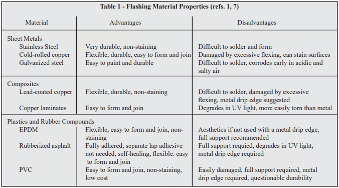
A wide variety of flashing materials are available. The selection of the type of flashing material to use can be influenced by several factors including cost, durability, compatibility with other materials, ease of installation, aesthetic value, and performance. Table 1 summarizes some of the attributes for various flashing materials. The advantages and disadvantages of each must be weighed for each individual project to provide the most cost-effective and desirable choice.
Prefabricated flashing boots may be available for inside and outside corners and end dams. These boots eliminate the need for cutting, folding, or tucking the flashing materials at these locations. However, due to construction tolerances, some of these prefabricated items, particularly those of rigid materials, may be difficult to fit into their intended location.
Table 1 – Flashing Material Properties (refs. 1, 7)
Sheet Metals
Stainless steel is technically any of a large and complex group of corrosion resistant iron chromium alloys possessing excellent weather and chemical resisting properties. Preformed sections must be properly sized so that on site modification is minimized. Stainless steel flashing with a conventional annealed finish should comply with Standard Specification for Stainless and Heat-Resisting Chromium-Nickel Steel Plate, Sheet, and Strip, ASTM A 167 (ref. 6). Generally, Type 304 stainless steel with a minimum thickness of 0.010 in. (0.25 mm) is satisfactory. Lap sections require solder conforming to Standard Specification for Solder Metal, ASTM B 32 (60% tin and 40% lead) (ref. 5). Stainless steel drip edges used in combination with other flashing materials offer an economical compromise with a durable drip edge.
Copper is a nonferrous metal possessing good ductility and malleability characteristics. Like stainless steel, it also possesses excellent weather and chemical resistant properties. Preformed sections or sheet materials are easily modified to conform to site requirements. However, it should be cautioned that once weathered, copper flashings produce a green patina that may impart a green stain to adjacent masonry surfaces that some find objectionable.
Galvanized steel is less expensive than stainless steel but is subject to corrosive attack from salts and acids. The galvanized coating also may crack at bends, lowering the corrosion resistance. As with stainless steel, it is also difficult to form and to solder laps effectively.
Composites
Combinations of metals and plastics are supplied by some dealers. The composition and application of these combined materials should be determined before use. Composites utilizing copper are the most popular since they combine the durability and malleability of copper with the nonstaining characteristics of a protective coating. Composites containing aluminum should be avoided.
Plastics and Rubber Compounds
Plastics are categorized as polymeric materials of large molecular weight, usually polyvinyl chloride (PVC) or polyethylene. Manufacturers of plastic flashings should be consulted for documentation establishing the longevity of the plastic in a caustic environment (pH = 12.5 to 13.5), the composition of the plastic, ease of working at temperatures ranging from 20 to 100 °F (-7 to 38 °C), and ability to withstand exposure to ultraviolet light.
Ethylene Propylene Diene Monomer (EPDM) is a synthetic rubber that is used as a single ply roofing membrane as well as flashing. It has better low temperature performance than PVC and will not embrittle. It offers ultraviolet light and ozone resistance and can be left exposed.
Self-adhering, rubberized asphalt membranes consist of a composite of flexible plastic film for puncture and tear resistance combined with a rubberized asphalt adhesive layer. This material adheres to itself, requiring less effort to seal laps or corners which speeds installation. It also self-adheres to the substrate which prevents water from migrating under the flashing and is self-healing in the event of punctures. However, it should not be applied to damp, dirty, or dusty surfaces and typically has a lower installation temperature limit of 25 °F (-4 °C). Because it degrades in the presence of extended UV exposure, it should not be left exposed and requires a metal drip edge.
CONSTRUCTION PRACTICES
To perform, flashing must be designed and installed properly or it may aggravate rather than reduce water problems. Flashing should be longitudinally continuous or terminated with end dams. Longitudinally continuous requires that joints be overlapped sufficiently, 4 in. (102 mm) minimum, to prevent moisture from entering between the joints and they must be bonded (joined) together with adhesive if they are not self adhering to prevent water movement through the lap area. With metal flashings a ¼ in. (6.4 mm) gap joined and sealed with a pliable membrane helps in accommodating expansion (ref. 3).
Flashings should be secured at the top by embedment into the masonry, a reglet, or should be adhesively attached so that water cannot infiltrate or move behind the attachment. For multi-wythe construction, the flashing should project downward along the outer surface of the inner wythe and then project outward at the masonry joint, shelf angle, or lintel where it is to discharge the water. Every effort should be made to slope the flashing towards the exterior. Effectively placed mortar or sealant material can help promote this drainage. The flashing should continue beyond the exterior face of the masonry a minimum of ¼ in. (6.4 mm) and terminate with a sloped drip edge.
An additional design consideration for flashings includes ensuring that all materials are compatible. For example, contact between dissimilar metals can result in the corrosion of one or both of the metals. Additionally, the coefficients of thermal expansion for the flashing and masonry materials differ. All flashing details should be designed to accommodate the resulting differential movement.
Other recommended practices involve the use of tooled concave mortar joints to reduce water penetration through the mortar joints. Masons should be careful to ensure that mortar dropped onto the flashing is minimized. This can be accomplished by beveling the mortar on the face shells adjacent to the cavities in cavity wall construction. In addition, cavity drainage mats, gravel beds, screens, or trapezoidal drainage material (filter paper) can be used to prevent mortar droppings from collecting on the flashing, which can form dams and block weep holes. Mortar collection devices at regular intervals or filling the cells with loose fill insulation a few courses at a time as the wall is laid-up, can be effective in dispersing minor mortar droppings enough to prevent clogging.
Weep holes, the inseparable companion to flashings, should provide free movement of water out of the concrete masonry cores, collar joints, or cavities. Any construction practice that allows forming the weep holes without inhibiting water flow may be used. Cotton sash cords and partially open head joints are the most common types of weep holes. Cotton sash cords should be removed prior to putting the wall into service to provide maximum unobstructed drainage. If necessary, insects can be thwarted by inserting stainless steel wool into the openings or using plastic or metal vents.
Vents
Weep holes often serve a dual function, first for water drainage and second as vents. Vents are desirable in some masonry wall systems to help reduce the moisture content of the masonry during drying periods. Air circulation through the cores and cavities within the masonry promotes equalization of moisture content throughout the masonry. Vents are considered desirable where air is confined within masonry, such as in parapets or areas of high humidity such as natatoriums.
MAINTENANCE
Maintenance programs should involve preserving the “as-built” design documents, records pertaining to inspections during the life of the structure, and continuing appraisal of the performance of the structure in addition to conventional repair and upkeep. Documentation of inspections, if efflorescence and water stains are observed, and logs of reported water penetration and their identified location, assist in determining proper corrective actions. Pictures with imprinted dates are suggested.
Knowledge of the wall design and construction can influence repair decisions. If flashing and weep holes were omitted during construction, it may prove effective to simply drill weep holes and vents to promote drainage and drying. Weep holes so drilled should be either at the intersection of the bed and head joints or into the cores at the bottom of the wall. Vents should be installed at the top of the wall or directly below bond beams. See TEK 08-01A Maintenance of Concrete Masonry Walls (ref. 4) for more detailed information on maintenance of concrete masonry walls.
When considering maintenance options, it is important to ensure that a masonry wall’s moisture control measures are kept intact. Thus, applying sealant beads, pargings, or coatings to a wall should be carefully weighed. Weep holes and vents should be maintained in an open condition to allow evacuation of moisture.
SUMMARY
Flashings are essential at foundations, bond beams, above and below openings, at shelf angles and at copings. Weep holes and vents reduce the moisture content of masonry walls. Proper selection of flashing materials, proper detailing, and proper installation will help ensure satisfactory performance.
REFERENCES
The Building Envelope: Solutions to Problems, Proceedings from a national seminar series sponsored by Simpson Gumpertz & Heger Inc., 1993.
Design for Dry Single-Wythe Concrete Masonry Walls, TEK 19-02B, Concrete Masonry & Hardscapes Association, 2012.
Flashing Details for Concrete Masonry Walls, TEK 19-05A, Concrete Masonry & Hardscapes Association, 2008.
Maintenance of Concrete Masonry Walls, TEK 08-01A, Concrete Masonry & Hardscapes Association, 2004.
Standard Specification for Solder Metal, ASTM B 32-04, ASTM International, 2004.
Standard Specification for Stainless and Heat-Resisting Chromium-Nickel Steel Plate, Sheet, and Strip, ASTM A 167-99(2004), ASTM International, 2004.
Through-Wall Flashing, Engineering and Research Digest No. 654, Brick Industry Association.
Water Repellents for Concrete Masonry Walls, TEK 19-01, Concrete Masonry & Hardscapes Association, 2006.
Using concrete masonry in retaining walls, abutments and other structural components designed primarily to resist lateral pressure permits the designer and builder to capitalize on masonry’s unique combination of structural and aesthetic features—excellent compressive strength; proven durability; and a wide selection of colors, textures and patterns. The addition of reinforcement to concrete masonry greatly increases the tensile strength and ductility of a wall, providing higher load resistance.
In cantilever retaining walls, the concrete base or footing holds the vertical masonry wall in position and resists overturning and sliding caused by lateral soil loading. The reinforcement is placed vertically in the cores of the masonry units to resist the tensile stresses developed by the lateral earth pressure.
DESIGN
Retaining walls should be designed to safely resist overturning and sliding due to the forces imposed by the retained backfill. The factors of safety against overturning and sliding should be no less than 1.5 (ref. 7). In addition, the bearing pressure under the footing or bottom of the retaining wall should not exceed the allowable soil bearing pressure.
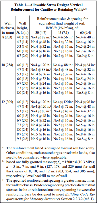
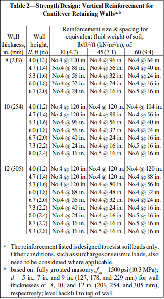
Recommended stem designs for reinforced cantilever retaining walls with no surcharge are contained in Tables 1 and 2 for allowable stress design and strength design, respectively. These design methods are discussed in detail in ASD of Concrete Masonry (2012 IBC & 2011 MSJC), TEK 14-07C, and Strength Design Provisions for Concrete Masonry, TEK 14-04B (refs. 5, 6).
Figure 2—Reinforced Cantilever Retaining Wall Design Example
DESIGN EXAMPLE
The following design example briefly illustrates some of the basic steps used in the allowable stress design of a reinforced concrete masonry cantilever retaining wall.
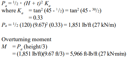
Example: Design the reinforced concrete masonry cantilever retaining wall shown in Figure 2. Assume level backfill, no surcharge or seismic loading, active earth pressure and masonry laid in running bond. The coefficient of friction between the footing and foundation soil, k1, is 0.25, and the allowable soil bearing pressure is 2,000 psf (95.8 kPa) (ref. 7).
F.S. (overturning) = total resisting moment about toe/overturning moment = 14,670/5,966 = 2.4 > 1.5 O.K.
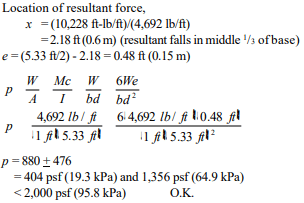
e. Pressure on footing
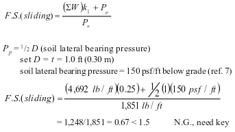
f. Determine size of key
Passive lateral soil resistance = 150 psf/ft of depth and may be increased 150 psf for each additional foot of depth to a maximum of 15 times the designated value (ref. 7). The average soil pressure under the footing is: ½ (1,356 + 404) = 880 psf (42.1 kPa).
Equivalent soil depth: 880 psf/120 pcf = 7.33 ft (2.23 m)
Pp = (150 psf/ft)(7.33 ft) = 1,100 psf (52.7 kPa)
For F.S. (sliding) = 1.5, the required total passive soil resistance is: 1.5(1,851 lb/ft) = 2,776 lb/ft (41 kN/m)
The shear key must provide for this value minus the frictional resistance: 2,776 – 1,248 = 1,528 lb/ft (22 kN/m).
Depth of shear key = (1,528 lb/ft)/(1,100 psf) = 1.39 ft (0.42 m), try 1.33 ft (0.41 m).
At 1.33 ft, lateral resistance = (1,100 psf) + (150 psf/ft)(1.33 ft) = 1,300 lb/ft (19 kN/m) Depth = (1,528 lb/ft)/[½ (1,100 + 1,300)] = 1.27 ft (0.39 m) < 1.33 ft (0.41 m) O.K.
g. Design of masonry
Tables 1 and 2 can be used to estimate the required reinforcing steel based on the equivalent fluid weight of soil, wall thickness, and wall height. For this example, the equivalent fluid weight = (Ka)(º) = 0.33 x 120 = 40 pcf (6.2 kN/m³).
Using allowable stress design (Table 1) and the conservative equivalent fluid weight of soil of 45 pcf (7.1 kN/m³), this wall requires No. 6 bars at 16 in. o.c. (M #19 at 406 mm o.c.). Using strength design (Table 2), this wall requires No. 5 bars at 16 in. o.c. (M #16 at 406 mm o.c.).
h. Design of footing
The design of the reinforced concrete footing and key should conform to American Concrete Institute requirements. For guidance, see ACI Standard 318 (ref. 2) or reinforced concrete design handbooks.
Table 1—Allowable Stress Design: Vertical Reinforcement for Cantilever Retaining Walls
Table 2—Strength Design: Vertical Reinforcement for Cantilever Retaining Walls
CONSTRUCTION
Materials and construction practices should comply with applicable requirements of Specification for Masonry Structures (ref. 4), or applicable local codes.
Footings should be placed on firm undisturbed soil, or on adequately compacted fill material. In areas exposed to freezing temperatures, the base of the footing should be placed below the frost line. Backfilling against retaining walls should not be permitted until the masonry has achieved sufficient strength or the wall has been adequately braced. During backfilling, heavy equipment should not approach closer to the top of the wall than a distance equal to the height of the wall. Ideally, backfill should be placed in 12 to 24 in. (305 to 610 mm) lifts, with each lift being compacted by a hand tamper. During construction, the soil and drainage layer, if provided, also needs to be protected from saturation and erosion.
Provisions must be made to prevent the accumulation of water behind the face of the wall and to reduce the possible effects of frost action. Where heavy prolonged rains are anticipated, a continuous longitudinal drain along the back of the wall may be used in addition to through-wall drains.
Climate, soil conditions, exposure and type of construction determine the need for waterproofing the back face of retaining walls. Waterproofing should be considered: in areas subject to severe frost action; in areas of heavy rainfall; and when the backfill material is relatively impermeable. The use of integral and post-applied water repellents is also recommended. The top of masonry retaining walls should be capped or otherwise protected to prevent water entry.
REFERENCES
Building Code Requirements for Masonry Structures, ACI 530-05/ASCE 5-05/TMS 402-05. Reported by the Masonry Standards Joint Committee, 2005.
Building Code Requirements for Structural Concrete and Commentary, ACI 318-02. Detroit, MI: American Concrete Institute, 2002.
Das, B. M. Principles of Foundation Engineering. Boston, MA: PWS Publishers, 1984.
Specification for Masonry Structures, ACI 530.1-05/ASCE 6-05/TMS 602-05. Reported by the Masonry Standards Joint Committee, 2005.
ASD of Concrete Masonry (2012 IBC & 2011 MSJC), TEK 14-07C, Concrete Masonry & Hardscapes Association, 2004.
Strength Design Provisions for Concrete Masonry, TEK 14-04B, Concrete Masonry & Hardscapes Association, 2008.
2003 International Building Code. International Code Council, 2003.
NOTATIONS
a length of footing toe, in. (mm) B width of footing, ft (m) d distance from extreme compression fiber to centroid of tension reinforcement, in. (mm) e eccentricity, in. (mm) F.S. factor of safety f’m specified compressive strength of masonry, psi (MPa) H total height of backfill, ft (m) I moment of inertia, ft4 (m4) Ka active earth pressure coefficient k1 coefficient of friction between footing and foundation soil M maximum moment in section under consideration, ft-lb/ft (kN⋅m/m) Pa resultant lateral load due to soil, lb/ft (kN/m) Pp passive earth pressure, lb/ft (N/m) p pressure on footing, psf (MPa) T thickness of wall, in. (mm) t thickness of footing, in. (mm) W vertical load, lb/ft (N/m) x location of resultant force, ft (m) º density of soil, pcf (kg/m³) ¤ angle of internal friction of soil, degreesDisclaimer: Although care has been taken to ensure the enclosed information is as accurate and complete as possible, NCMA does not assume responsibility for errors or omissions resulting from the use of this TEK.