Design for Dry Single-Wythe Concrete Masonry Walls
INTRODUCTION
Single-wythe concrete masonry walls are cost competitive because they provide structural form as well as an attractive and durable architectural facade. However, because they do not have a continuous drainage cavity (as do cavity and veneered walls), they require special attention to moisture penetration.
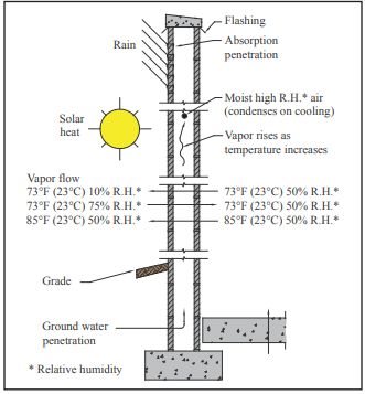
The major objective in designing dry concrete masonry walls is to keep water from entering or penetrating the wall. In addition to precipitation, moisture can find its way into masonry walls from a number of different sources (see Figure 1). Dry concrete masonry walls are obtained when the design and construction addresses the movement of water into, through, and out of the wall. This includes detailing and protecting building elements including parapets, roofs, all wall penetrations (utility and fire protective openings, fenestration, doors, etc.), movement joints, sills and other features to resist water penetration at these locations. Annotated Design and Construction Details for Concrete Masonry (ref. 1) contains comprehensive details for reinforced and unreinforced concrete masonry walls. Further, condensation and air leakage must be controlled. See the Condensation Control section on page 7.
The primary components of moisture mitigation in concrete masonry walls are flashing and counter flashing, weeps, vents, water repellent admixtures, sealants (including movement joints), post-applied surface treatments, vapor retarders and appropriate crack control measures. For successful mitigation, all of these components should be considered to be used redundantly, however not all will be applicable to all wall systems. For example, flashing and weeps are not necessary in solidly grouted construction, and may not be appropriate in areas of high wind or seismic loading where compromise of masonry shear resistance may occur (see the Wall Drainage section on page 3 for more information). The determination on structural effect must be made by the structural engineer. As another example, the use of integral water repellents for surfaces to receive a stucco finish may not be appropriate. Successful design for moisture mitigation considers each of these components, and provides for redundancy of protection, also known as a “belt and suspenders” approach.
This TEK provides a brief overview of the issues to consider when designing single wythe walls for water penetration resistance. The information presented is not meant to be comprehensive. Where appropriate, references to more detailed sources are provided.
SOURCES OF WATER IN WALLS
Driving Rain
Although concrete masonry units and mortar generally do not allow water to pass through quickly, rain can pass through if driven by a significant force. Cracks caused by building movements, or gaps between masonry and adjoining building elements are common points of water entry. If rain enters wall other than by way of the roof or at element interfaces (such as penetrations and window openings), it often can be traced to the masonry unit-mortar interface.
Capillary Action
Untreated masonry materials (without a compatible integral water repellent and/or post-applied surface treatment) typically take on water through absorption, adsorption and/or capillary forces. The amount of water depends on the characteristics of the masonry and mortar. Integral water repellents greatly reduce the absorption and adsorption characteristics of the units and mortar, but may not be able to prevent all moisture migration if there is a significant head pressure of approximately 2 in. water (51 mm) or more. Post-applied surface treatments reduce moisture penetration of masonry at the treated surface as well, but have little effect on the interior of the units.
Water Vapor
Water as vapor moves through a wall either via air leakage or by diffusion (from higher to lower: relative humidity, pressure and/or temperature). As air cools, it becomes more saturated, and when it reaches the dew point temperature the water vapor will condense into liquid form. See the Condensation Control section on page 7 for more information.
Ground Water
Protecting below-grade walls from water entry involves installing a barrier to water and water vapor. Below grade moisture tends to migrate from the damp soil to the drier area inside the basement. An impervious barrier on the exterior wall surface can prevent moisture entry. The barrier is part of a comprehensive system to prevent water penetration, which includes proper wall construction and the installation of drains, gutters, and proper grading (location of finished grade as well as grade sloping away from the building). Landscaping can also contribute to water ponding adjacent to the foundation wall and/or to insufficient drainage. IBC Section 1805 contains requirements for dampproofing and water proofing foundations. More detailed information for concrete masonry foundation walls can be found in Preventing Water Penetration in Below Grade CM Walls, TEK 19-03B (ref. 2).
DESIGN CONSIDERATIONS
When designing for moisture mitigation in walls, three levels of defense should be considered: surface protection (properly constructed mortar joints, surface water repellents, surface coatings), internal protection (integral water repellents), and drainage/drying (flashing, weeps, vents). The most successful designs often provide redundancy among these three levels. This redundant design approach helps ensure that the wall remains free of moisture problems even if one of the defense mechanisms is breached. Flashing and weeps, for example, provide a backup in case surface coatings are not reapplied as needed or leaks develop around windows or other openings. The following sections discuss the individual mechanisms in more detail.
Physical Characteristics of the Units
Open-textured concrete masonry units possessing large voids tend to be more permeable than closed-textured units. The texture can be affected by aggregate gradation, water content of the concrete mix, amount of cement in the mix, other materials in the mix such as admixtures, and the degree of compaction achieved during molding. These factors can also affect capillary action and vapor diffusion characteristics. Units should be aged at least 21 days if possible before installation to reduce the chance of shrinkage cracks at the mortar-unit interface.
Smooth-faced units facilitate mortar joint tooling, so will generally result in a more water resistant wall, as opposed to fluted units which are more difficult to tool and therefore the most susceptible to leakage. Horizontal effects such as corbels and ledges that may hold water are more prone to water penetration.
Integral Water Repellents
The use of integral water repellents in the manufacture of concrete masonry units can greatly reduce the wall’s absorption characteristics. When using units with an integral water repellent, the same manufacturer’s water repellent for mortar must be incorporated in the field for compatibility and similar reduced capillary action characteristics.
Integral water repellents make masonry materials hydrophobic, significantly decreasing their water absorption and wicking characteristics. While these admixtures can limit the amount of water that can pass through units and mortar, they have little impact on moisture entering through cracks and voids in the wall. In addition, when using an integral water repellent, any water that does penetrate can not exit as easily. Therefore, even with the incorporation of integral water repellents, flashing and weeps, as well as proper detailing of control joints and quality workmanship are still essential. See Water Repellents for Concrete Masonry Walls, TEK 19-01 (ref. 3), and Characteristics of CMU with Integral Water Repellent, TEK 19-07 (ref. 4), for more complete information on integral water repellents for concrete masonry walls.
Post-Applied Surface Treatments
For integrally colored architectural masonry, a clear surface treatment should be post-applied whether or not integral water repellent admixtures are used. Most post-applied coatings and surface treatments are compatible with integral water repellents although this should be verified with the product manufacturers before applying. When using standard units for single-wythe walls, application of a clear treatment, portland cement plaster (stucco), paint, or opaque elastomeric coating improves the water resistance of the wall. Coatings containing elastomerics have the advantage of being able to bridge small gaps and TEK 19-02B 3 CONCRETE MASONRY & HARDSCAPES ASSOCIATION masonryandhardscapes.org cracks. See Water Repellents for Concrete Masonry Walls, TEK 19-01 (ref. 3) for more detailed information.
Wall Drainage
In areas with high seismic loads, masonry walls tend to be heavily reinforced and it is often more economical to fully grout the masonry. In fully grouted masonry, flashing is not necessary. In these cases, the wall is designed as a barrier wall, rather than as a drainage wall.
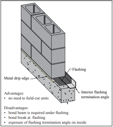
When flashing is used, the importance of proper detailing cannot be over-emphasized. Traditionally, through-wall flashing has been used to direct water away from the inside wall face and toward weep holes for drainage. Figure 2 shows one example of flashing that spans completely across the width of the wall. In this example, the termination angle prevents any water that collects on the flashing from penetrating to the interior, and the weeps and drip edge drain water to the exterior.
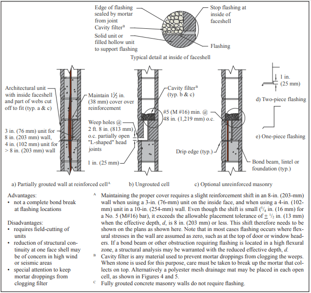
Where it is necessary to retain some shear and flexural resistance capabilities, there are several options. One is to terminate the flashing within the inside face shell of the wall, as shown in Figure 3. In reinforced walls, some shear is provided through doweling action of the reinforcement, and by design the reinforcement takes all tension (refs. 5, 6). Proper grouting effectively seals around where the vertical reinforcement penetrates the flashing. The absence of reinforcement to provide doweling in plain masonry may be more of a concern, but loads tend to be relatively low in these applications. If structural adequacy is in doubt, a short reinforcing bar through the flashing with cells grouted directly above and below can be provided as shown in Figure 3c.
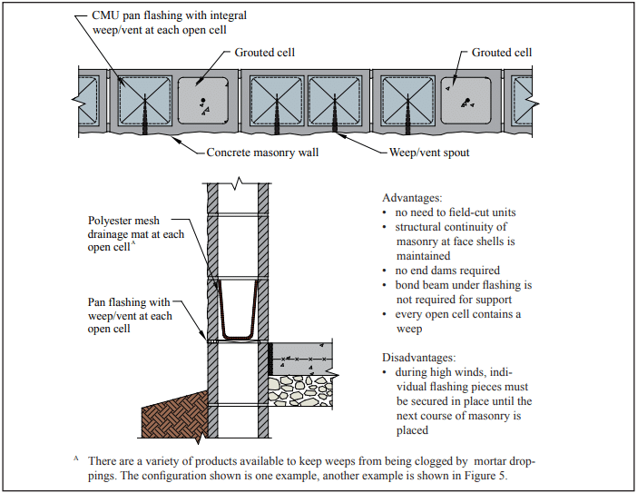
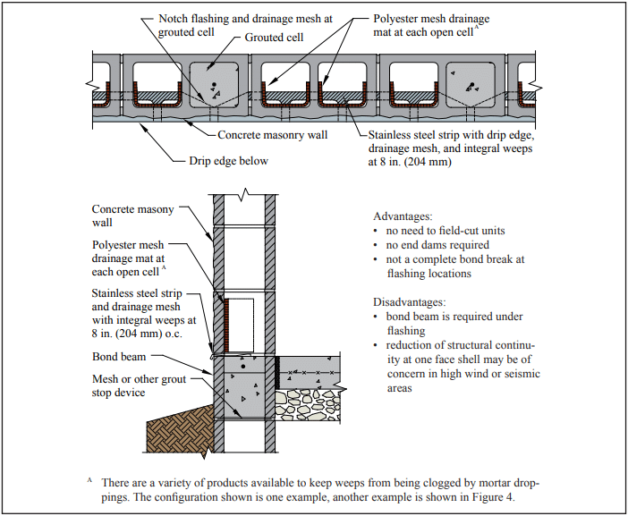
A better option to maintain shear at the level of the flashing is to use a product that maintains some bond in both face shells, such as that shown in Figure 4.
Ensuring that a buildup of mortar droppings does not clog the cells or weep holes is critical. Traditionally, a cavity filter consisting of washed pea stone or filter paper immediately above the flashing was provided to facilitate drainage, as shown in Figure 3. This should be accompanied by a means of intercepting or dispersing mortar droppings, as an accumulation can be sufficient to completely fill and block a cell at the bottom. As an alternative, mortar interception or isolation devices that provide pathways for the water to migrate through the layer of mortar droppings, or filling the cells with loose fill insulation a few courses at a time as the wall is laid up, can disperse the droppings enough to prevent clogging. Examples of polyester mesh drainage mats are shown in Figures 4 and 5. Another alternative is to leave out facing block at regular intervals just above the flashing until the wall is built to serve as cleanouts. The units left out can be mortared in later. See Flashing Strategies for Concrete Masonry Walls, TEK 19-04A and Flashing Details for Concrete Masonry Walls, TEK 19-05A, (refs. 7, 8) for an in-depth discussion and additional details regarding flashing.
In addition to conventional flashing systems, proprietary flashing systems are available that direct the water away from the inside face of the wall to weep holes without compromising the bond at mortar joints in the face shells. See Figure 4 for one example. These are not intended to be comprehensive, but rather to provide examples of some types of available systems. Specialty units that facilitate drainage are also available from some manufacturers.
Solid grouted single-wythe walls do not require flashing because they are not as susceptible to moisture penetration, since voids and cavities where moisture can collect are absent. However, fully cured units and adequate crack control measures are especially important to minimize cracks. In some regions of the country, the bottom of the wall is recessed about 1 in. (25 mm) below the floor level to ensure drainage to the exterior.
Crack Control
Because cracks provide an entry point for rainwater and moist air, crack control provisions are very important in producing dry walls. There are various sources of potential wall cracking. A detailed list, as well as an overview of crack control strategies, can be found in Crack Control Strategies for Concrete Masonry Construction, CMU-TEC-009-23 (ref. 9).
Control joints and/or horizontal reinforcement should be located and detailed on the plans to alleviate cracking due to thermal and shrinkage movements of the building. Specifying a quality sealant for the control joints and proper installation is a must to maintain the weather-tightness of the joint. Joint Sealants for Concrete Masonry Walls, TEK 19-06A (ref. 10) contains more comprehensive information on this topic. See Crack Control Strategies for Concrete Masonry Construction, CMU-TEC-009-23 (ref. 11) for detailed information on control joint placement and construction.
Mortar and Mortar Joints
The type of mortar and type of mortar joint can also impact a wall’s watertightness. A good rule of thumb is to select the lowest strength mortar required for structural and durability considerations. Lower strength mortars exhibit better workability and can yield a better weather-resistant seal at the mortar/unit interface. See Mortars for Concrete Masonry, TEK 09-01A (ref. 12), for a more complete discussion.
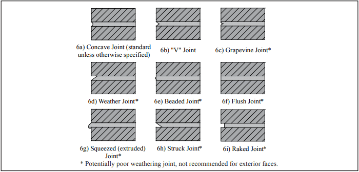
Unless otherwise specified, mortar joints should be tooled to a concave profile when the mortar is thumbprint hard (refs. 5, 13), as shown in Figure 6. For walls exposed to weather, concave joints improve water penetration resistance by directing water away from the wall surface. In addition, because of the shape of the tool, the mortar is compacted against the concrete masonry unit to seal the joint. V-shaped joints result in sharper shadow lines than concave joints. Raked, flush, struck, beaded, grapevine, squeezed or extruded joints are not recommended in exposed exterior walls as they do not compact the mortar and/or they create ledges that intercept water running down the face of the wall.
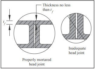
Head and bed joints should be the full thickness of the face shells for optimum water resistance. Head joints are particularly vulnerable to inadequate thickness (see Figure 7).
Condensation Control
Condensation is a potential moisture source in building assemblies. Because condensation potential varies with environmental conditions, seasonal climate changes, the construction assembly, building type and building usage, condensation control strategies vary as well. For a full discussion, see Condensation Control in Concrete Masonry Walls, TEK 06-17B, and Control of Air Leakage in Concrete Masonry Walls, TEK 06-14A (refs. 14, 15).
Note that the location and vapor permeability of insulation can influence the condensation potential of a wall. The following references provide more detailed information. Insulating Concrete Masonry Walls, TEK 06-11A (ref. 16), discusses various insulation strategies and the advantages and disadvantages of each. R-Values and U-Values for Single Wythe Concrete Masonry Walls, TEK 06-02C, and Thermal Catalog of Concrete Masonry Assemblies (refs. 17, 18) provide calculated thermal values of various walls and insulation types. Details for Half-High Concrete Masonry Units, TEK 05-15 (ref. 19), contains comprehensive details of various single wythe walls.
Cleaning
Concrete masonry cleaning methods can generally be divided into four categories: hand cleaning, water cleaning, abrasive cleaning and chemical cleaning. In general, the least aggressive method that will adequately clean the wall should be used, as overzealous cleaning can damage the water repellent characteristics of the wall. Keeping the masonry wall clean as the construction progresses using a brush and water minimizes cleaning efforts after the mortar has hardened. See Cleaning Concrete Masonry, TEK 08-04A (ref. 20) for more detailed information.
SPECIFICATIONS
Well-worded specifications are essential to ensure the design details are properly constructed. Items to address in the contract documents in addition to those previously mentioned include:
- All work to be in accordance with the International Building Code and Specification for Masonry Structures (refs. 5, 13).
- Require a qualified mason by documentation of experience with similar type projects.
- Require sample panels to assure an understanding of the level of workmanship expected and to be used as a standard of reference until the project is completed.
- Proper storage of all masonry materials (including sand) at the job site to protect from contaminants such as dirt, rain and snow.
- The tops of unfinished walls shall be covered at the end of each work day. The cover should extend 2 ft (610 mm) down each side of the masonry and be held securely in place.
REFERENCES
- Annotated Design and Construction Details for Concrete Masonry, TR 90. National Concrete Masonry Association, 2002.
- Preventing Water Penetration in Below-Grade CM Walls, TEK 19-03B, Concrete Masonry & Hardscapes Association, 2012.
- Water Repellents for Concrete Masonry Walls, TEK 19-01, Concrete Masonry & Hardscapes Association, 2006.
- Characteristics of CMU with Integral Water Repellent, TEK 19-07, Concrete Masonry & Hardscapes Association, 2008.
- International Building Code. International Code Council, 2012.
- Building Code Requirements for Masonry Structures, TMS 402-11/ACI 530-11/ASCE 5-11, reported by the Masonry Standards Joint Committee, 2011.
- Flashing Strategies for Concrete Masonry Walls, TEK 1904A, Concrete Masonry & Hardscapes Association, 2008.
- Flashing Details for Concrete Masonry Walls, TEK 19-05A, Concrete Masonry & Hardscapes Association, 2008.
- Crack Control Strategies for Concrete Masonry Construction, CMU-TEC-009-23, Concrete Masonry & Hardscapes Association, 2023.
- Joint Sealants for Concrete Masonry Walls, TEK 19-06A, Concrete Masonry & Hardscapes Association, 2014.
- Crack Control Strategies for Concrete Masonry Construction, CMU-TEC-009-23, Concrete Masonry & Hardscapes Association, 2023.
- Mortars for Concrete Masonry, TEK 09-01A, Concrete Masonry & Hardscapes Association, 2004.
- Specification for Masonry Structures, TMS 602-11/ACI 530.1-11/ASCE 6-11, reported by the Masonry Standards Joint Committee, 2011.
- Condensation Control in Concrete Masonry Walls, TEK 06-17B, Concrete Masonry & Hardscapes Association, 2011.
- Control of Air Leakage in Concrete Masonry Walls, TEK 06-14A, Concrete Masonry & Hardscapes Association, 2011.
- Insulating Concrete Masonry Walls, TEK 06-11A, Concrete Masonry & Hardscapes Association, 2010.
- R-Values and U-Values for Single Wythe Concrete Masonry Walls, TEK 06-2C, Concrete Masonry & Hardscapes Association, 2012.
- Thermal Catalog of Concrete Masonry Assemblies, CMU-MAN-004-12, Concrete Masonry & Hardscapes Association, 2012.
- Details for Half-High Concrete Masonry Units, TEK 05-15, Concrete Masonry & Hardscapes Association, 2010.
- Cleaning Concrete Masonry, TEK 08-04A, Concrete Masonry & Hardscapes Association, 2005.


