Resources

Concrete Masonry Fence Design

INTRODUCTION

Concrete masonry fences and garden walls are used to fulfill a host of functions, including privacy and screening, security and protection, ornamentation, sound insulation, shade and wind protection.

In addition, concrete masonry provides superior durability, design flexibility and economy. The wide range of masonry colors and textures can be used to complement adjacent architectural styles or blend with the natural landscape.

Because fences are subjected to outdoor exposure on both sides, selection of appropriate materials, proper structural design and quality workmanship are critical to maximize their durability and performance.

STRUCTURAL DESIGN

Masonry fences are generally designed using one of five methods:

  1. as cantilevered walls supported by continuous footings;
  2. as walls spanning between pilasters, that are, in turn, supported by a footing pad or caisson;
  3. as walls spanning between wall returns that are sufficient to support the wall;
  4. as curved walls with an arc-to-chord relationship that provides stability; or
  5. as a combination of the above methods.

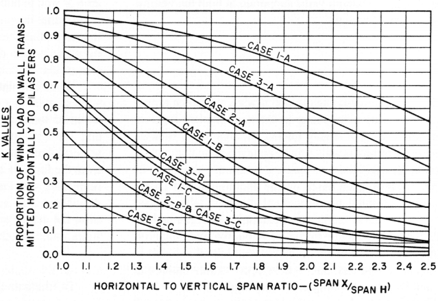
This TEK covers cases (a) and (d) above, based on the provisions of the 2003 and 2006 editions of the International Building Code (refs. 1, 2). Although fences up to 6 ft (1,829 mm) high do not require a permit (refs. 1 and 2, Ch.1), this TEK provides guidance on design and construction recommen- dations. Fences designed as walls spanning between pilasters (case b) are covered in TEK 14-15B, Allowable Stress Design of Pier and Panel Highway Sound Barrier Walls (ref. 3). In addition, fences can be constructed by dry-stacking and surface bonding conventional concrete masonry units (see ref. 4), or by utilizing proprietary dry-stack fence systems.

CANTILEVERED FENCE STRUCTURAL DESIGN

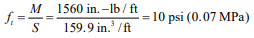
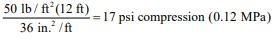
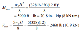
Tables 1, 2 and 3 provide wall thickness and vertical reinforcement requirements for cantilevered walls for three lateral load cases: lateral load, w ≤ 15 psf (0.71 kPa), 15 < w ≤ 20 psf (0.95 kPa), and 20 < w ≤ 25 psf (1.19 kPa), respectively. For each table, footnote A describes the corresponding wind and seismic conditions corresponding to the lateral load, based on Minimum Design Loads for Buildings and Other Structures, ASCE 7 (ref. 5).

Assumptions used to develop Tables 1, 2 and 3 are:

  1. strength design method
  2. except as noted, designs comply with both the 2003 and 2006 International Building Code,
  3. running bond masonry,
  4. ASTM C 90 (ref. 6) concrete masonry units,
  5. specified compressive strength of masonry, f’m = 1,500 psi (10.3 MPa)
  6. ASTM C 270 (ref. 7) mortar as follows: Type N, S or M portland cement /lime mortar or Type S or M masonry cement mortar (note that neither Type N nor masonry cement mortar is permitted to be used in SDC D),
  7. ASTM C 476 (ref. 8) grout,
  8. Grade 60 reinforcing steel, reinforcement is centered in the masonry cell,
  9. depth from grade to top of footing is 18 in. for 4- and 6-ft (457 mm for 1.2- and 1.8-m) high fences; 24 in. for 8-ft (610 mm for 2.4-m) high fences, and
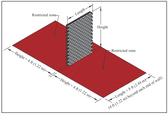
  10. reinforcement requirements assume a return corner at each fence end with a length at least equal to the exposed height. Where fence ends do not include a return, increase the design lateral load on the end of the fence (for a length equal to the exposed height) by 5 psf (34.5 kPa).

FOOTINGS

For cantilevered walls, the footing holds the wall in position and resists overturning and sliding due to lateral loads. Dowels typically extend up from the footing into the wall to transfer stresses and anchor the wall in place. Dowels should be at least equal in size and spacing to the vertical fence reinforcement. The required length of lap is determined according to the design procedure used and type of detail employed. For the design conditions listed here, the No. 4 (M#13) reinforcing bars require a minimum lap length of 15 in. (381 mm), and the No. 5 (M#16) bars require a minimum lap length of 21 in. (533 mm). Refer to TEK 12-06a, Splices, Development and Standard Hooks for Concrete Masonry (ref. 9) for detailed information on lap splice requirements.

Footings over 24 in. (610 mm) wide require transverse reinforcement (see footnotes to Table 4). For all footings, the hook should be at the bottom of the footing (3 in. (76 mm) clearance to the subgrade) in order to develop the strength of the bar at the top of the footing.

The footing designs listed in Table 4 conform with Building Code Requirements for Reinforced Concrete, ACI 318 (ref. 10). Note that concrete for footings placed in soils containing high sulfates are subject to additional requirements (refs. 1, 2).

SERPENTINE WALLS

Serpentine or “folded plate” wall designs add interesting and pleasing shapes to enhance the landscape. The returns or bends in these walls also provide additional lateral stability, allowing the walls to be built higher than if they were straight.

Serpentine and folded plate walls are designed using empirical design guidelines that historically have proven successful over many years of experience. The guidelines presented here are based on unreinforced concrete masonry for lateral loads up to 20 psf (0.95 kPa). See Table 2, footnote A for corresponding wind speeds and seismic design parameters.

Design guidelines are shown in Figure 2, and include:

  • wall radius should not exceed twice the height,
  • wall height should not exceed twice the width (or the depth of curvature, see Figure 2),
  • wall height should not exceed fifteen times the wall thickness, and
  • the free end(s) of the serpentine wall should have additional support such as a pilaster or a short-radius return.

A wooden template, cut to the specified radius, is helpful for periodically checking the curves for smoothness and uniformity. Refer to TEK 5-10A, Concrete Masonry Radial Wall Details (ref. 11) for detailed information on constructing curved walls using concrete masonry units.

CONSTRUCTION

All materials (units, mortar, grout and reinforcement) should comply with applicable ASTM standards. Additional material requirements are listed under the section Cantilevered Fence Structural Design, above.

To control shrinkage cracking, it is recommended that horizontal reinforcement be utilized and that control joints be placed in accordance with local practice. In some cases, when sufficient horizontal reinforcement is incorporated, control joints may not be necessary. Horizontal reinforcement may be either joint reinforcement or bond beams. See CMU-TEC-009-23, Crack Control Strategies for Concrete Masonry Construction (ref. 12) for detailed guidance.

In addition, horizontal reinforcement in the top course (or courses if joint reinforcement is used) is recommended to help tie the wall together. For fences, it is not structurally necessary to provide load transfer across control joints, although this can be accomplished by using methods described in CMU-TEC-009-23 if deemed necessary to help maintain the fence alignment.

Copings provide protection from water penetration and can also enhance the fence’s appearance. Various materials such as concrete brick, cast stone, brick and natural stone are suitable copings for concrete masonry fences. Copings should project at least ½ in. (13 mm) beyond the wall face on both sides to provide a drip edge, which will help keep dripping water off the face of the fence. In cases where aesthetics are a primary concern, the use of integral water repellents in the masonry units and mortar can also help minimize the potential formation of efflorescence.

REFERENCES

  1. 2003 International Building Code. International Code Council, 2003.
  2. 2006 International Building Code. International Code Council, 2006.
  3. Allowable Stress Design of Pier and Panel Highway Sound Barrier Walls, NCMA TEK 14-15B. Concrete Masonry & Hardscapes Association, 2004.
  4. Design and Construction of Dry-Stack Masonry Walls, TEK 14-22. National Concrete Masonry Association, 2003.
  5. Minimum Design Loads for Buildings and Other Structures, ASCE 7-02 and ASCE 7-05. American Society of Civil Engineers, 2002 and 2005.
  6. Standard Specification for Loadbearing Concrete Masonry Units, ASTM C 90-01a and C 90-03. ASTM International, Inc., 2001 and 2003.
  7. Standard Specification for Mortar for Unit Masonry, ASTM C 270-01a and C 270-04. ASTM International, Inc., 2001 and 2004.
  8. Standard Specification for Grout for Masonry, ASTM C 476-01 and C 476-02. ASTM International, Inc., 2001 and 2002.
  9. Splices, Development and Standard Hooks for Concrete Masonry, TEK 12-06A. Concrete Masonry & Hardscapes Association, 2007.
  10. Building Code Requirements for Structural Concrete, ACI 318-02 and ACI 318-05. Detroit, MI: American Concrete Institute, 2002 and 2005.
  11. Concrete Masonry Radial Wall Details, TEK 5-10A. Concrete Masonry & Hardscapes Association, 2006.
  12. Crack Control in Concrete Masonry Walls, TEK 10-1A. Concrete Masonry & Hardscapes Association, 2005.

Designing Concrete Masonry Walls for Wind Loads

INTRODUCTION

Traditionally, empirical requirements have been used for the selection of masonry wall dimensions and lateral support spacing for resistance to wind pressures. These empirical requirements provide satisfactory results for buildings less than 35 ft (11 m) in height where the basic wind pressure does not exceed 25 psf (1197 Pa). This TEK addresses those cases where it is necessary or desirable to undertake a more thorough structural analysis of the lateral wind resistance of a concrete masonry wall or wall-pilaster combination.

Such analysis involves a knowledge of the magnitude and distribution of the wind force to various elements of a masonry structure and the flexural and shear strength of these elements. The information in this TEK provides guidelines for the design of masonry walls supported in both the vertical and horizontal directions.

WALLS

The need to investigate the lateral wind resistance capacity of a wall is usually greater in the case of plain (unreinforced) nonbearing or lightly loaded masonry walls because the vertical load on the wall may be insufficient to completely offset the development of flexural tension. Analysis of masonry walls is often based on the assumption that lateral loads are transmitted in the vertical direction with no end fixity at the lateral supports. Although this approach is straightforward, it may be overly conservative when the ratio of horizontal to vertical distances between lateral supports is relatively small and end fixity is developed. In such cases, end fixity and two-way bending can be utilized.

When wind loads are applied normal to a masonry wall surface, the loads are transmitted to horizontal supports (floors, roofs, beams) and/or vertical supports (cross walls, pilasters). Wall panels are usually assumed to function structurally as thin plates or slabs. For simplicity, walls are often designed to span horizontally between vertical supports or to span vertically between horizontal supports. However, walls can be designed assuming two-way bending using pilasters or cross walls as well as the roof structure and footing as supports. Assuming that the flexural resistance and rigidity of the walls in both the vertical and horizontal spans are known, the lateral load capacity and the proportion of the lateral load transmitted vertically and horizontally to the edge supports will depend on the restraint developed at the edges, the horizontal to vertical span ratio of the panel, and the distribution of the loads applied to the wall panels.

The curves in Figure 1 can be used to approximate the proportion of wind load transmitted in the vertical and horizontal directions. These curves are based on the assumption that the moment of inertia and modulii of elasticity of the walls will be the same in both the horizontal and vertical directions. The curves were derived by equating the theoretical formulas for calculating the maximum deflection for a strip of wall in both directions. It was further assumed that the walls either have no openings, or that any wall openings are located so that their effect on the stiffness of the wall panel is the same in both directions, and that the wall panels on each side of the support are similar in length and height.

When calculating the wind load to be carried by a vertical support, such as a pilaster, a value for K corresponding to the assumed support conditions at the edges of the wall panels and the appropriate wall panel length-to-height ratio is selected from the curves. Then, the value of wp is determined from the formula given at the top of Figure 1. This value, wp, represents the load which, when applied as a uniformly distributed load over the height of the pilaster, will approximate the actual wind load transmitted to the pilaster by the walls under the design conditions.

Design Example

To illustrate the use of the curves and formula given in Figure 1, assume a building with exterior walls spanning 12 ft (3.7 m) vertically between the floor and the roof is designed to resist a wind pressure of 20 psf (958 Pa). The walls are also supported horizontally at 18 ft (5.5 m) by pilasters which are built integrally with the wall. The roof loads will be carried by trusses simply supported on the pilasters, so the walls will be considered free at the top and fixed at the bottom and at the pilasters.

Selecting the appropriate value for K from the curve given for Case 1-A and a wall length-to-height ratio of 18/12 or 1.50, the wind load per foot of height to be carried by the pilasters, wp, may be calculated as follows:

wp =KwX
wp = (0.91) (20 psf) (18 ft)
= 328 lb/ft (4787 N/m)

The value of 328 lb/ft (4787 N/m) represents the uniformly distributed load which, when considered to be applied over the full height of the pilaster, will approximate the actual load transmitted to the pilasters by the adjacent walls under the design conditions. The moment and shear developed in the pilasters as a result of this load will depend on the assumed top and bottom support conditions for the pilaster.

The wall construction consists of 12 in. (305 mm) hollow concrete masonry units laid in running bond with face shell mortar bedding, using Type N portland cement lime mortar. Additional design information includes:

Section modulus, S = 159.9 in.³/ft (0.009 m³/m)
Net area, An = 36 in.²/ft (0.08 m²/m)
Allowable tensile stress parallel to bed joints = 1.33 x 38 psi = 50.5 psi (0.35 MPa) (ref. 1)
Allowable tensile stress normal to bed joints = 1.33 x 19 psi = 25.3 psi (0.17 MPa) (ref. 1)

As already determined, the horizontal span carries 91% of the wind load. With the wall fixed at the ends, the maximum moment, M, in the horizontal span (from Figure 2) is:

The flexural tensile stress in the horizontal span, ft, is:

The allowable tensile stress for hollow units, Type N mortar, tension parallel to bed joints, was determined to be 50.5 psi (0.35 MPa). Since the calculated tensile stress is less than the allowable, the design meets the code criteria.

In the vertical span, the wall described above carries 9% (1 – 0.91) of the wind load. Since the wall is free at the top and fixed at the base, the maximum moment is:

The flexural tensile stress in the vertical span is:

This value can be reduced by the dead load stress on the wall at the point of maximum moment. Assuming that the wall weighs 50 lb/ft² (2394 N/m²):

This results in a net axial compressive stress of 7 psi (48.3 Pa).

PILASTERS

A pilaster is a thickened wall section or vertical support built contiguous with and forming a part of the masonry wall. Pilasters are often used to stiffen masonry walls and to provide all or part of the lateral support. They may be built of hollow or solid units (manufactured in one or two pieces), grouted hollow units or reinforced hollow units. Pilasters function primarily as flexural members when used only for lateral support although they can also be used to support vertical compressive loads.

When designing pilasters, the lateral loads transmitted to the pilasters by the adjacent wall panels must be determined. Figure 1 can be used to approximate the proportion of wind load which is transmitted horizontally to pilasters and to calculate the approximate wind load carried by a pilaster.

The formulas given in Figure 2 can be used to calculate the maximum moment and shear on a pilaster after wp and the support conditions for the pilaster have been determined.

Consider the design described in the previous design example. From Figure 1, it was determined that for Case 1-A with span ratio of 1.5, approximately 91% of the wind load is transmitted in the horizontal span. If the pilasters in the above example are assumed to be fixed at the bottom and simply supported at the top, the maximum moment and shear values are as follows:

The pilaster, therefore, should be designed to provide an allowable moment and shear resistance equal to or greater than the above values.

NOTATION:

An     = net cross-sectional area of masonry, in.²/ft (m²/m)
ft       = flexural tension in masonry, psi (MPa)
H      = height of wall, ft (m)
K       = proportion of wind load transmitted horizontally to pilasters or cross walls
M      = moment, in.-lb/ft (N•m/m)
S        = section modulus, in.³/ft (m³/m)
Vmax = maximum shear, lb/ft (N/m)
w       = uniformly distributed wind load, psf (Pa)
wd     = design wind load on wall, psf (Pa)
wp     = uniform lateral load which approximates the actual wind load transmitted by the walls to the pilasters or cross walls, lb/ft of height (N/m)
X       = horizontal span of wall, from center to center of pilasters or cross walls, ft (m)

REFERENCES

  1. Building Code Requirements for Masonry Structures, ACI 530-92/ASCE 5-92/TMS 402-92. Reported by the Masonry Standards Joint Committee, 1992.

TEK 14-03A, Revised 1995.

Rolling Door Details for Concrete Masonry Construction

INTRODUCTION

Openings in concrete masonry walls utilize lintels and beams to carry loads above the openings. When openings incorporate rolling doors (also referred to as overhead coiling doors or coiling doors), wind loads on the door are transferred to the surrounding masonry through the door guides and fasteners.

In some instances, the rolling doors have been designed for specific wind load applications, and are heavily dependent on the structural integrity of the door jamb members as they are attached to building walls at jamb locations. This TEK discusses the forces imposed on a surrounding concrete masonry wall by rolling doors, and includes recommended details for jamb construction. Lintel design, to carry the loads imposed on the top of the opening, are covered in Allowable Stress Design of Concrete Masonry Lintels and Precast Concrete Lintels for Concrete Masonry Construction (refs. 1, 2).

LOADS EXERTED BY ROLLING DOORS

Architects and building designers should determine the loads that rolling doors exert on the wall around the opening. Dead loads include the weight of the door curtain, counterbalance, hood, operator, etc., that is supported by the wall above the opening. Live loads result from wind that acts on the door curtain. Rolling doors are available with windlocks, which prevent the door curtain from leaving the guides due to wind loading. On doors without windlocks, the only wind load force that the curtain exerts on the guides is normal to the opening. For doors with windlocks, there is an additional load parallel to the opening (see Figures 1 and 2 for face-mounted and jambmounted doors, respectively). This load is the catenary tension that results when the curtain deflects sufficiently to allow the windlocks to engage the windbar in the guide. This force acts to pull the guides toward the center of the opening. The door is exposed to a additive wind loads, from both inside and outside the building.

Calculating the parallel force involves several variables, the most prominent of which are the width of the opening and the design wind load. It is also important to note that the door must withstand both positive and negative wind loads. Including these forces in the design of the jamb and its supporting structure can help prevent a jamb failure and allow the building to fully withstand its specified wind load requirements. The rolling door manufacturer can provide a guide data sheet for quantifying the loads imposed by the overhead coiling doors due to the design wind load.

The following conditions need to be considered:

  • The wall above the door opening must be designed to support the total hanging dead load. The face of wallmounted doors may extend above the opening for 12 to 30 in. (305-762 mm). The door guide wall angles must be mounted to the wall above the opening to support the door. When the door has a hood to cover the coiled door and counter-balance, some provision must be made to fasten the top of the hood and hood supports to the masonry wall. See also Fasteners for Concrete Masonry (ref.3).
  • Reinforcement in jambs is recommended to adequately distribute the forces imposed by the door.
  • Reinforcement locations should be planned such that the reinforcement does not interfere with expansion anchor placement.

ACCOMODATING MASONRY REINFORCEMENT AND DOOR FASTENERS

Rolling door contractors and installers sometimes encounter reinforcement in walls at locations where door jamb fasteners have been specified. Arbitrarily changing either the reinforcement location or the fastener location is not recommended, as either can negatively impact performance. Changing the door manufacturer’s recommended jamb fastener locations may reduce the structural performance of the rolling door or possibly void the fire rating.

The typical masonry jamb detail shown in Figure 3 indicates recommended vertical reinforcement locations for concrete masonry jambs to provide an area for the door fasteners. The detail shows a “reinforcement-free zone” to allow for fasteners of either face mounted or jamb-mounted rolling doors. The Door and Access Systems Manufacturers Association International (DASMA) recommends that vertical reinforcement should be within 2 in. (51 mm) of either corner of the wall at the jamb (ref. 4).

EXISTING CONSTRUCTION

Before installing fasteners in existing masonry construction, the following steps should be followed to locate the reinforcement, to avoid interference:

  • If structural drawings are available, the project engineer should review the drawings to determine whether or not the jamb reinforcement locations conflict with the specified door jamb fastener locations.
  • If the building’s structural plans are not available, either drill
    representative “pilot holes” or use a device similar to an electronic stud locator to determine the steel reinforcement locations.

Once the steel reinforcement has been located, if it is concluded that the reinforcement will interfere with installing jamb fasteners, DASMA recommends that one of the following courses of action be taken:

  1. Consider an alternate door jamb mounting or door size to assure that the reinforcement will not interfere with jamb fasteners.
  2. If an alternate door jamb mounting or alternate door size cannot be accomplished, consult a structural engineer to determine a workable solution. One possible solution is to contact the door manufacturer to obtain an alternate conforming hole pattern for the mounting, which would not interfere with the existing reinforcement. Another solution may be to bolt a steel angle to the concrete masonry jambs, which allows the door guides to then be welded or bolted to the steel angle.

FIRE-RATED ROLLING DOOR CONNECTIONS

When installed in a fire-rated concrete masonry wall, rolling steel fire doors must meet the code-required fire rating corresponding to the fire rating of the surrounding wall. For fire testing, the doors are mounted on the jambs of a concrete masonry wall intended to replicate field construction. The fire door guides must remain securely fastened to the jambs and no “through gaps” may occur in the door assembly during the test. Figure 4 shows a representative jamb construction and guide attachment details for a four-hour fire rated assembly. Note that guide configurations and approved jamb construction will vary with individual fire door manufacturer’s listings. Consult with individual manufacturers for specific guide details and approved jamb constructions.

REFERENCES

  1. Allowable Stress Design of Concrete Masonry Lintels
    Based on 2012 IBC/2011 MSJC, TEK 17-01D, Concrete
    Masonry & Hardscapes Association, 2011.
  2. Precast Concrete Lintels for Concrete Masonry
    Construction, TEK 17-02A, Concrete Masonry &
    Hardscapes Association, 2000.
  3. Fasteners for Concrete Masonry, TEK 12-05, Concrete
    Masonry & Hardscapes Association, 2005.
  4. Metal Coiling Type Door Jamb Construction: Steel
    Reinforcement In Masonry Walls, TDS-259. Door and
    Access Systems Manufacturers Association International,
    2005.
  5. Architects and Designers Should Understand Loads
    Exerted By Overhead Coiling Doors, TDS-251. Door and
    Access Systems Manufacturers Association International,
    2005.
  6. International Building Code 2003. International Code
    Council, 2003.
  7. International Building Code 2006. International Code
    Council, 2006.
  8. Common Jamb Construction for Rolling Steel Fire Doors:
    Masonry Construction—Bolted and Welded Guides, TDS-
  9. Door and Access Systems Manufacturers Association
    International, 2005.
  10. Steel Reinforcement for Concrete Masonry, TEK 12-04D,
    Concrete Masonry & Hardscapes Association, 2006.

Bracing Concrete Masonry Walls Under Construction

INTRODUCTION

Building codes typically place responsibility for providing a reasonable level of life safety for workers during construction on the erecting contractor. Various methods are employed to protect workers while newly constructed masonry walls are curing and/or until the roof or other structural supports are in place. This TEK provides guidelines for masonry wall stability to resist the lateral loading effects of wind during construction. It is based on principles set forth in the Council for Masonry Wall Bracing’s Standard Practice for Bracing Masonry Walls Under Construction (ref. 1), but has been updated in accordance with the design provisions of the 2011 Building Code Requirements for Masonry Structures (MSJC, ref. 2).

When other lateral loads such as impact, seismic, scaffolding, and lateral earth pressure are present, they need to be considered and evaluated separately. The Walls Subject to Backfilling section at the end of this TEK discusses bracing and support of basement walls during backfilling operations.

WALLS SUBJECT TO WIND LOADS

There are several strategies and considerations for protecting life safety on the jobsite. These include internal bracing, external bracing and evacuation zones. The combination of strategies appropriate for a particular job may depend on the type of masonry construction, masonry wall heights, the time elapsed since construction, and wind speeds at the site.

The industry term “internal bracing” is relatively new. Internal bracing refers to the stability of a masonry assembly to resist wind loads through self-weight and allowable flexural stresses within the masonry.

The use of evacuation zones recognizes that it may be impractical to prevent the collapse of a masonry wall during construction when subjected to extreme loading conditions and that life safety is the primary concern. At prescribed wind speeds (taken as three-second gusts measured at the job site), the wall and the area around it is evacuated. The critical wind speed resulting in evacuation depends on the age of the wall being constructed and involves the three terms: “restricted zone,” “initial period,” and “intermediate period.”

Restricted Zone

The restricted zone is the area on each side of a wall subject to the effect of a masonry wall collapse. It is defined by a length equal to the height of the constructed wall plus 4 ft (1.22 m) on both sides of the wall, and a width equal to the wall length plus 4 ft (1.22 m) on both ends of the wall, as shown in Figure 1. When wind speeds exceed those allowed during the initial and intermediate periods, there is a chance that the masonry wall could fail, and the restricted zone must be evacuated in order to ensure life safety.

Initial Period

The initial period is the period of time, not to exceed 24 hours, during which the masonry is being laid above its base or highest line of bracing, and at the end of which required bracing is installed. During this period, the mortar is assumed to have no strength and wall stability is accomplished from the masonry self-weight only. Based on this assumption and a wind speed limit of 20 mph (8.9 m/s), walls can be built to the heights shown in Table 1 without bracing during the initial period. If wind speeds exceed 20 mph (8.9 m/s) during the initial period, work on the wall must cease and the restricted zone on both sides of the wall must be evacuated. Evacuation for walls up to 8 ft (2.44 m) above grade is not necessary until wind speeds reach 35 mph (15.6 m/s) in keeping with a long-standing OSHA requirement.

Intermediate Period

The intermediate period is the period of time following the initial period but before the wall is connected to the elements that provide its final lateral support. The design wind speed is 40 mph (17.9 m/s) 3-second gust for brace design. When the wind speed exceeds 35 mph (15.6 m/s), the restricted zone must be evacuated. The difference of 5 mph (2.2 m/s) is to allow workers time to evacuate the area.

During the intermediate period, the masonry is assumed to have one-half of its design compressive strength and plain masonry allowable flexural stresses are taken as two-thirds of the design value given in the 2011 MSJC (ref. 2). The masonry structural capacity then can be determined using these reduced values in accordance with the provisions of the Code (see ref. 3 for more information).

There are several methods of providing an acceptable level of life safety for masons and others working on the construction site. They are:

  1. bracing to a design wind speed of 40 mph (17.9 m/s), 3-second gust and evacuating if the wind speed exceeds 35 mph (15.6 m/s), 3-second gust,
  2. alternative bracing designs and methods approved, sealed, and signed by a registered professional engineer if supported by data representing field conditions, and
  3. an early warning and evacuation program when the masonry is designed to resist a wind speed of 5 mph (2.2 m/s) greater than the designated evacuation wind speed. The wind speed measurement must be made by an instrument with a ± 2 mph (0.89 m/s) accuracy.

Traditionally, bracing and evacuation of the restricted zones has also been based on wind speeds lower that 35 mph (15.6 m/s). As such, Table 2 addresses evacuation wind speeds of 15 and 25 mph (6.7 and 11.2 m/s) in addition to the 35 mph (15.6 m/s) evacuation wind speed. Many jurisdictions will accept the lower wind speed criteria but users should first confirm acceptability with their local building official and/or OSHA representative before using them.

Table 2 lists maximum unbraced wall heights when early warning with an evacuation program is implemented. Design wind speeds for the heights in Table 2 are for 5 mph (2.2 m/s) greater than the evacuation speed to allow time for the masons to get off the scaffolding and evacuate the restricted zone.

Figure 2 shows a wood brace detail for support heights up to 14′-4″ (4.37 m) maximum. Proprietary pipe bracing systems and cable systems are also available for all heights shown in Table 2—see manufacturer’s recommendations for details.

Research has shown that properly designed and constructed reinforcement splices can achieve up to 75% of the specified yield stress of the reinforcing steel at 12 hours and 100% at 24 hours (ref. 1). Therefore, the full capacity of splices may be used after grout has been in place 24 hours. Alternatively, the full splice capacity can be used after only 12 hours if the design lap length is increased by one-third. Splice criteria is as follows for Grade 60 reinforcement:

  • 48 bar diameters for grout that has been in place 24 hours or more,
  • 64 bar diameters for grout that has been in place 12 hours or more but less than 24 hours.

Connections to masonry can be designed using the previously described reduced masonry strengths and design formulas. As an alternate, restricted working loads for post- drilled anchors as reported in the manufacturer’s literature may be used.

Design Example

Determine the bracing requirements for a 22 ft (6.71 m) tall wall constructed with 8 in. (203 mm) concrete masonry having a density of 110 lb/ft3 (1762 kg/m3) and reinforced with No. 5 bars at 32 in. (M#16 at 813 mm) o.c. using 30 in. (762 mm) splice lengths (i.e., 48 bar diameters). Mortar is masonry cement Type S, control joints are spaced at 24′-8″ (7.52 m), and flashing is at the base of the wall only (unbonded condition).

Initial Period

From Table 1:

Maximum unsupported height = 10′-0″ (3.05 m). (These initial period provisions apply to all of the options that follow.)

Intermediate Period—Unbraced Option

From Table 2:

Alternate 1: Evacuation wind speed of 15 mph (6.7 m/s).

NOTE: Although this type of option has historically been accepted, the designer should verify acceptance with the local building official and/or OSHA representative.

Unreinforced wall:

Maximum height above grade, unbonded = 10′-0″ (3.05 m)

Maximum height above grade or line of support, bonded = 23′-0″ (7.01 m)

Reinforced wall:

Maximum height, bonded or unbonded = 23′-4″ (7.11 m) for No. 5 at 48 in. (M#16 at 1.22 m)

This is conservative, because the wall in this example has reinforcement spaced closer than 48 in. (1.22 m).

Strategy:

Build the wall to a height of 10′-0″ (3.05 m) the first day (initial period).

The maximum height for an unbonded condition during the intermediate period is 10′-0″ (3.05 m) for this wind speed, therefore neither bracing nor grouting is required for the 10′-0″ (3.05 m) height during the intermediate period.

If the wall is reinforced and grouted, it can support a total height of 23′-4″ (7.11 m). Therefore, if the first 10′-0″ (3.05 m) is reinforced and grouted, another 10′-0″ (3.05 m) (initial period limit) could be built 24 hours after grout placement if the standard 30 in. (1,016 mm) reinforcement splice is used (or after 12 hours with a 40 in. (762 mm) splice). The 10′- 0″ (3.05 m) height is less than the 23′-0″ (7.01 m) unbraced limit for the bonded unreinforced intermediate period and the total 20′-0″ (6.10 m) of constructed wall height is less than the reinforced limit of 23′-4″ (7.11 m).

The next day, the top 2 ft (0.61 m) of masonry can be added, because the initial period limit of 10′-0″ (3.05 m) is met, the maximum unreinforced bonded limit of 23′-0″ (7.01 m) is met, and the reinforced limit of 23′-4″ (7.11 m) is met. Therefore, the wall can be built in this manner without external bracing.

NOTE: This option requires early warning and evacuation when wind speeds reach 15 mph (6.7 m/s) 3-second gust. This may not be practical in all areas.

Alternate 2: Design for an evacuation wind speed of 35 mph (15.6 m/s).

Unreinforced wall:

Maximum height above grade, unbonded = 8′-0″ (2.44 m) at ground level (see Table 2 note G), 2′-8″ (0.81 m) otherwise, Maximum height above grade or line of support, bonded = 10′-0″ (3.05 m)

Maximum vertical spacing between braces, bonded = 12′-4″ (3.75 m)

Maximum vertical height above brace, bonded = 6′-0″ (1.82 m)

Reinforced wall:

Maximum height above grade or line of support, bonded 23′-4″ (7.11 m)

Maximum vertical spacing between braces, bonded = 28′-0″ (8.53 m)

Maximum vertical height above brace, bonded = 14′-0″ (4.26 m)

Strategy:

Build the wall to a height of 10 ft (3.05 m) the first day (Table 1: initial period limit is 10′-0″ (3.05 m)). Grout that lift the same day, which after the curing period (12 or 24 hours depending on the splice length used) can support a cantilever height of 23′-4″ (7.11 m).

Then, build an additional section of wall of 6′-0″ (1.82 m) high, grout it and brace it at no lower than the 8′-0″ (2.43 m) level, because only 14′-0″ (4.26 m) of the reinforced 22 ft (6.71 m) wall can extend above the brace.

The next or following days, finish the rest of the wall and grout that portion the same day. (Note the first two sections each could have been done in 8′-0″ (2.44 m) heights as well.)

The brace will need to stay in place until the permanent support (roof or floor) is in place. Note that when counting reinforced internal bracing, the wall must be grouted the same day and the restricted zone vacated for the next 12 or 24 hours, depending on the splice length used.

NOTE: Refer to the International Masonry Institute’s Internal Bracing Design Guide for Masonry Walls Under Construction (ref. 4). That demonstrates how to effectively use low-lift grouting for internal bracing, as each lift that is grouted can be considered reinforced and able to withstand higher loadings at the bottom of the wall where stresses are highest.

WALLS SUBJECT TO BACKFILLING

Unless concrete masonry basement walls are designed and built to resist lateral earth pressure as cantilever walls, they should not be backfilled until the first floor construction is in place and anchored to the wall or until the walls are adequately braced. Figure 3 illustrates one type of temporary lateral bracing being used in the construction of concrete masonry basement walls. Heavy equipment, such as bulldozers or cranes, should not be operated over the backfill during construction unless the basement walls are appropriately designed for the higher resulting loads.

Ordinarily, earth pressures assumed in the design of basement walls are selected on the assumption that the backfill material will be in a reasonably dry condition when placed. Because lateral earth pressures increase as the moisture content of the earth increases, basement walls should not be backfilled with saturated materials nor should backfill be placed when any appreciable amount of water is standing in the excavation. Similarly, water jetting or soaking should never be used to expedite consolidation of the backfill.

Care should be taken to avoid subjecting the walls to impact loads, as would be imparted by earth sliding down a steep slope and hitting the wall. This could also damage waterproofing, dampproofing, or insulation applied to the walls. Also, if needed, a concrete masonry unit can be left out at the bottom of a wall to prevent an unbalanced accumulation of water. The unit can be replaced before backfilling.

REFERENCES

  1. Standard Practice for Bracing Masonry Walls Under Construction. Council for Masonry Wall Bracing, December 2012.
  2. Building Code Requirements for Masonry Structures, TMS 402-11/ACI 530-11/ASCE 5-11. Reported by the Masonry Standards Joint Committee, 2011.
  3. Allowable Stress Design of Concrete Masonry Based on the 2012 IBC and 2011 MSJC, TEK 14-07C. Concrete Masonry & Hardscapes Association, 2013.
  4. Internal Bracing Design Guide for Masonry Walls Under Construction. International Masonry Institute, May 2013 (available free at www.imiweb.org).
  5. Basement Manual: Design and Construction Using Concrete Masonry, CMU-MAN-002-01, Concrete Masonry & Hardscapes Association, 2001.