Resources

Do Manufactured Concrete Products Sequester CO2?

Revised 2024

Yes. From the moment a concrete masonry unit (CMU), segmental retaining wall (SRW) unit, concrete paver or slab, or other manufactured concrete product is formed, the material will begin to bind chemically to the carbon dioxide (CO2) in the environment. This sequestration, also referred to as carbonation or uptake of CO2 will continue indefinitely if there is a source of hydrated, hydraulic cement exposed to carbon dioxide. Because the very nature of concrete means the presence of hydrated cement, and because it is virtually impossible to prevent exposure to CO2, carbon sequestration is in essence a fundamental characteristic of concrete.

The fact that concrete masonry carbonates and sequesters CO2 has been well documented for decades [1]. Past research efforts, however, have focused simply on the fact that concrete masonry absorbs carbon dioxide, without defining how much, or how quickly, CO2 is absorbed. As the sustainable attributes and environmental impact of different construction materials becomes an increasingly important design objective, questions such as these continue to be raised. In the context of recognizing that CO2 is released during the manufacturing of portland related hydraulic cements, the evolution of this question then becomes how much CO2 is subsequently reabsorbed during the service life of the concrete product.

BASICS OF THE CARBON CYCLE OF CONCRETE

To answer this question, let’s go back to the beginning and look at the whole carbon cycle of concrete. First, portland cement is manufactured by combining limestone, clay and silica sand and heating them up in large rotary kilns to about 2700 °F (1500 °C). During this process CO2 is released to the atmosphere from the decomposition of the limestone and from the burning of the fuels needed to heat the kiln. Approximately 50% of the released CO2 comes from the decomposition of the limestone (which is referred to as calcination carbon emissions), 40% comes from the fuel combustion, and 10% comes from the other cement manufacturing plant processes. Overall, approximately 900 kg of CO2 is released per 1000 kg of portland cement produced. This is referred to as the embodied carbon or carbon footprint of the cement.

Next, concrete, including manufactured concrete products, is made up of a mixture of the portland cement combined with sand and stone. When these materials are mixed together with water, the cement hydrates during the curing process forming the ‘glue’ that holds the sand and stone together in the hardened concrete. While portland cement makes up only 7 to 20% of the total concrete mixture, it is the largest contributing factor to the embodied carbon in the final concrete and can contribute from 75 to over 90% of total embodied carbon of the concrete.

Finally, when the cement hydrates, it forms hydrated cement gel (which is the ‘glue’) and a byproduct called calcium hydroxide. From the moment concrete is produced and the cement begins to hydrate, it begins to reverse the calcination carbon emissions chemical reaction that originally released CO2 and starts to sequester CO2 from the atmosphere. Initially, this sequestered CO2 chemically combines with the calcium hydroxide byproduct to form calcium carbonate (also called limestone) which permanently locks the CO2 back into the matrix of the concrete. The sequestered CO2 also continues reacting with the cement gel to be permanently locked into the matrix as carbonated cement paste.

CARBONATION RATE – THE DIFFERENCE
BETWEEN DRY-CAST AND WET-CAST
CONCRETE

The speed at which the concrete sequesters CO2 is called the carbonation rate and is related to exposure conditions and the porosity of the concrete. The more open the structure of the concrete, the faster and further the CO2 can penetrate into the concrete to react with the calcium hydroxide and cement gel. This is where dry-cast manufactured products like CMU have a distinct advantage compared to regular wet-cast concrete. Because of the nature of the dry-cast manufacturing process, the CMU have interconnected voids throughout the concrete which allow carbon dioxide to easily penetrate into the dry-cast matrix. Coupled with the configuration of concrete masonry units (CMU), consisting of relatively thin face shells and webs, this results in signifi cantly higher natural carbonation rates of CMU compared to wet-cast concrete. By contrast, wet-cast concrete is more massive and does not have interconnected voids – the CO2 can only penetrate much more slowly through the small capillaries in the concrete matrix.

The carbonation rate of wet-cast concrete has been thoroughly studied and modeled. Reported carbonation rates of wetcast concrete vary from 1 to 5 mm (0.04 to 0.20 in.) per year depending on a multitude of factors, including the composition, curing, porosity, and permeability of the concrete, as well as the presence of moisture, and exposure conditions. Current models [2] indicate that 3000 psi wet-cast concrete under ideal exposure conditions would have carbonation uptakes of less than 2 kg/m3 of concrete at 28-days of age and approximately 8 kg/m3 after being exposed for 2 years. These are a small fraction of the total embodied carbon of the concrete – equivalent to less than 1% of the concrete’s total embodied carbon at 28-days of age and less than 3% after 2 years.

Until recently the carbonation rate of dry-cast concrete has not been systematically studied. In 2020, the NCMA Foundation undertook a study to measure the carbon sequestration rate of nine sets of CMU from across North America. The study culminated in a peer reviewed paper delivered at the ASTM Masonry Symposium [3]. The paper documented the results for the nine sets from ages of 28-days to 6-months and verified that CMU have a significantly higher rate of carbonation even in the manufacturing phase, or Cradle to Gate. CMHA has continued studying these nine sets and now has 2-year exposure data. The data show that on average the CMU had carbonation uptakes (or sequestered CO2 levels) of 19 kg/m3 of concrete at 28-days of age (considered to be the gate) and 42 kg/m3 after being exposed for 2 years. These represent 21% (at 28 days) and 49% (at 2 years) of the calcination carbon emissions originally
released from the limestone during the manufacturing of the cement. These are a significant fraction of the total embodied carbon of the concrete (which includes additional raw materials (like aggregates), CMU plant operations, and emissions from both the chemical reaction and for heating during cement production) – equivalent to about 8% of the concrete’s total embodied carbon at 28 days (gate) and approximately 18% after 2 years into the use phase of the building. Modeling of the current data indicates that these values may increase to 25% of the concrete’s total embodied carbon during the first 20 to 25 years of a building’s lifetime.

For the CMHA study, the CMU were stored outside in typical weather conditions for the Mid-Atlantic US, representative of (and applicable to) the wide range of exposure conditions and applications for CMU. Specific exposure conditions for a given application may impact sequestration results. CMHA is continuing to undertake more research to better understand and quantify CMU and other dry-cast concrete products ability to sequester CO2. While the current results are based on one wide-ranging study, the results reinforce CMUs reputation as one of the most sustainable and resilient building systems available.

REFERENCES

  1. CMU-TEC-009-23, Crack Control Strategies for Concrete Masonry Construction, Concrete Masonry & Hardscapes Association, 2023.
  2. MIT ‘s Whole Life Cycle Carbon Uptake Tool found on the MIT Concrete Sustainability Hub website, https://cshub.mit.edu/whole-life-cycle-carbon-uptake-tool/
  3. Conceptual Test Protocols for Measuring Carbon Sequestration of Manufactured Dry-Cast Concrete Products, C. Walloch, L. Powers, D. Broton, J. Thompson, in Masonry 2022: Advancing Masonry Technology, ed. B. Trimble, J. Farny (West Conshohocken, PA: ASTM International, 2022), 59–86, https://doi.org/10.1520/
    STP164020210112.

The Effects of Deicing Chemicals on Interlocking Concrete Pavers

Revised 2018

Interlocking concrete pavements are a flexible and durable system that performs successfully in the most demanding applications, conditions and climates. One of the most extreme conditions is the application of deicing chemicals to prevent or reduce ice buildup which can contribute to slips, falls and loss of vehicular control. This FAQ outlines factors that contribute to a low risk of damage from deicing materials on concrete pavers.

UNIT PROPERTIES IMPACTING PAVER DURABILITY

Ice that may form and expand inside the paver can cause stresses that may lead to degradation. Deicing materials mixed with the ice can increase the damage potential. Properly manufactured concrete pavers, however, are very durable and resistant to degradation because the high density of a paver limits deicing material from entering. In addition, a high cement content helps a paver resist damage from the stress of expanding ice. Research and experience have highlighted factors affecting the winter durability of concrete pavers, including the utilization of:

  • Aggregates with low absorption that will not degrade when subject to freezing and thawing and deicing materials;
  • Proper aggregate gradation that allows for high density when compacted during manufacturing;
  • Sufficient cement paste to coat the aggregate and reduce capillary pores; and
  • Sufficient compaction during manufacturing to ensure maximum density and uniformity.

Units manufactured with these characteristics typically yield a high density, low absorption, high compressive strength, resulting in a durable paver.

ASTM C936 Standard Specification for Solid Concrete Interlocking Paving Units includes freeze-thaw durability criteria for assessing the freeze-thaw durability and resistance to deicing salts. C936 references the test method ASTM C1645 Standard Test Method for Freeze-thaw and De-icing Salt Durability of Solid Concrete Interlocking Paving Units. C936 includes an optional lower freezing temperature for regions of the United States that experience severe freezing conditions based on a climatic zone map. The optional testing in 3% saline for these regions is equivalent to the testing required in the Canadian concrete paver standard, CSA A231.2 Precast Concrete Pavers. To obtain a copy of ASTM C936 or ASTM C1645 visit www.astm.org. The CSA standard is available from www.csagroup.org.

COMPARISON TO READY MIXED CONCRETE

Properly air-entrained and finished ready-mix concrete can resist freeze-thaw degradation, although over-finished, cast-inplace slabs or those made with re-tempered concrete with too much water can be susceptible to surface scaling. Compared to ready-mixed concrete, concrete pavers have the following advantages when exposed to freeze-thaw conditions and deicing agents:

  • Stronger aggregate bonding from higher cement content than typically used in pavement quality ready-mix concrete;
  • Smaller aggregates (more surface area for the cement to bond);
  • Lower water/cement ratio as well as vibration and compaction during the manufacturing process to increase aggregate-cement contact and to eliminate the possibility of over-watering;
  • Produced in a highly controlled manufacturing plants leading to lower variation in material properties with elimination of an over-finished surface; and
  • Can be successfully installed in cold weather because they are properly cured before they leave the manufacturing plant.

Research prepared for the Utah Department of Transportation* in 2013 found that concrete exposed to sodium chloride experienced only minor, if any, adverse effects, while specimens exposed to calcium chloride, magnesium chloride, or calcium magnesium acetate (CMA) experienced significant deterioration, including scaling, cracking, mass loss, and compressive strength loss. While the literature review did not specifically address unit pavers, the findings are directly related to cured unit concrete properties. The report recommends that engineers responsible for winter maintenance of concrete pavements should utilize sodium chloride whenever possible, instead of calcium chloride, magnesium chloride, or CMA, and apply only the amount absolutely necessary to ensure safety of the traveling public. These findings support CMHA’s guidelines for deicing salt exposure. *Physical and Chemical effects of Deicers on Concrete Pavement: Literature Review, Report No. UT-13.09 Prepared for Utah Department of Transportation Research Division by Brigham Young University, July 2013

GUIDELINES FOR LIMITING DEICING CHEMICAL EXPOSURE

A key to successfully using deicing materials on unit concrete pavers is using only as much as needed to do the job. This will maximize their benefits while minimizing any damage to the concrete pavers and surrounding environment. The following guidelines can help limit the exposure of deicing chemicals while maintaining a safe environment:

  • Rock salt (sodium chloride or NaCl) is the least damaging to concrete materials and should be used whenever possible.
  • If a more effective, quicker acting deicer is necessary, consider the judicial use of calcium chloride.
  • The use of magnesium chloride or CMA is not recommended because they can chemically degrade all types of concrete, significantly increasing potential damage. The potential for damage from CMA increases with the amount of magnesium in the formulation.
  • Do not over apply deicing chemicals; follow the recommended dosage.
  • Do not use deicing chemicals in place of snow removal but reserve them for melting ice formed by freezing precipitation or freezing snow melt.
  • Once loosened, snow, ice and excess deicing salts should be promptly removed by plow or shovel to avoid a buildup in concentration of the deicing chemical(s).
  • Protect vegetation and metal from contact with deicing chemicals as most can impair vegetation and corrode metals.
  • Sand used in the winter for traction on permeable interlocking concrete pavements is not recommended. If used, sand must be removed with vacuuming in the spring to prevent a substantial decrease in surface infiltration.
  • Using jointing aggregate is recommended as a better alternative to using sand when winter traction is needed on permeable interlocking concrete pavements. In addition, the aggregate can provide some refilling of the joints.

In addition, use CMHA-recommended jointing and bedding sand materials to minimize water penetration into the pavers. This can also help reduce salts from entering and accumulating in the jointing and bedding sand that may eventually degrade the pavers. CMHA also recommends adequate pavement slopes (typically a minimum of 2%) to facilitate surface water drainage and help remove deicing materials. While not essential, reduction of water entering jointing sand can be further enhanced with joint sand stabilization materials and/or sealers.

DEICING CHEMICAL COMPARISON CHART

The following chart compares common deicing chemicals with respect to their effective temperature, plus their impact on the potential freeze-thaw degradation and on chemical degradation of the concrete.

*Effective temperature is lowest practical temperature of the deicer defined as the lowest temperature at which the relative melting potential (MP) is 0.7 as calculated in reference 1 below.

* Information adapted from National Cooperative Highway Research Program Report 577 “Guidelines for the Selection of Snow and Ice Control Materials to Mitigate Environmental Impacts” ©2007 Transportation Research Board

Which Software can be Utilized for the Design of Segmental Retaining Walls?

Revised 2023

When seeking to design segmental retaining walls, there are several professional-grade software packages available. Each package contains different functionality and complies with the different design methodologies to different degrees. It is advisable for the designer to thoroughly review the software and understand any differences it may have with the standard design approaches. Here are some key details to consider when selecting the appropriate software for your project’s needs:

ENGINEERING DESIGN OF THE WALL:

Both gravity and reinforced walls must be designed to meet the specific requirements of the chosen method. Several design methods are available, depending on the nature of the project. For most residential and commercial walls, the Concrete Masonry & Hardscape Association (CMHA) (formerly NCMA) method is commonly used. Transportation projects may require the American Association of Highway and Transportation Officials (AASHTO) or Federal Highway (FHWA) methods, while some transportation agencies might have their specific approaches.

  • Generic Software Options for Design Methods: There are suitable software solutions to assist with the design based on widely available methods. For example, the CMHA 3rd edition design method has a nonproprietary companion software. Other nonproprietary software options are REA or Vespa. Alternatively, for AASHTO or FHWA methods, MSEW+ and Vespa are suitable options.
  • Proprietary Software Considerations: Proprietary software following chosen design methods are also suitable solutions. This vendor supplied software is already populated with system specific data and only analyzes the vendors proprietary products. This is typically supplied by the SRW System Supplier.

A complete segmental retaining wall design requires the evaluation of several forms of potential failure. This could include external stability (sliding, overturning and bearing capacity checks), internal stability (overstress, pullout, and international sliding checks), facial stability (crest toppling and connection checks) and possibly internal compound stability.

GLOBAL STABILITY ANALYSIS:

In cases where an analysis of the wall’s global stability is required, certain software programs can handle 2D global stability analysis effectively. Examples of such software include Slide2, Slope/W (2D analysis) or Slope3D (3D analysis), or ReSSA+. Designers can input all relevant wall conditions into these programs for analysis.

LIMIT EQUILIBRIUM ANALYSIS:

This newest method uses slope stability to model the driving and stabilizing loads on a wall and it is usually used in very complicated projects. As of now, the only available software is ReSSA+.

It’s important to note that currently, there is no single software solution that can handle the wall design, global stability analysis, and the limit equilibrium method. Therefore, a combination of appropriate software may be needed to address all aspects of a project effectively.

SOFTWARE MENTIONED IN THIS FAQ:
  • SRWall 5.0 from CMHA
  • MSEW+ and Ressa+ from Adama Engineering: geoprograms.com
  • REA Analysis from Race Engineering: rea-llc.com/technical/#software
  • Slide 2 from Rocscience: rocscience.com
  • SLOPE/W and SLOPE3D from GeoSlope: geoslope.com
  • Vespa from CTiSoftware: ctiware.com/vespa
  • Proprietary Software, contact your SRW supplier to find out if they have their own software

The list of software presented here is not intended as a CMHA endorsement nor it is all-inclusive. CMHA has not verified accuracy of calculations so the designer is encouraged to do so when selecting a software aid.

What Is the Difference Between Fire Resistance Ratings for Masonry Assemblies Obtained Through IBC Vs. a Listing Service Such as UL or FM?

Revised 2023

In practical terms, there is little difference in the resulting fire resistance ratings for concrete masonry assemblies determined by each of the code-recognized methods. A concrete masonry assembly that is rated 2 hours, for example, using one method would be rated the same using any of the other permitted compliance options; within expected deviations associated with reproducibility of any test. The differences reside primarily in the procedures used by each process to determine the fire resistance rating, each affording their own unique advantages and disadvantages in application.

Because differences in the resulting fire resistance rating obtained through physical testing versus calculation, for example, are nominal, the International Building Code (IBC) permits the use of multiple compliance options as follows:

  • Physical evaluation in accordance with ASTM E119, Standard Test Methods for Fire Tests of Building Construction and Materials or UL263, Fire Tests of Building Construction and Materials. While two distinct standards, the testing procedures outlined in ASTM E119 and UL263 are nearly identical, and as such produce very similar fire resistance ratings for concrete masonry assemblies.
  • Calculated fire resistance determined in accordance with Section 721 of the IBC. The calculated fire resistance method is an adaptation of the standard ACI/TMS 216.1 [4], Code Requirements for Determining Fire Resistance of Concrete and Masonry Construction Assemblies. The calculated fire resistance is derived from hundreds of tests conducted on concrete masonry assemblies tested in accordance with ASTM E119.
  • Prescriptive detailing requirements in accordance with Section 721 of the IBC. These include commonly used concrete masonry wall assemblies that are deemed-tocomply with a prescribed level of fire resistance based on historical testing in accordance with ASTM E119 or UL263.
  • Alternative modeling or designs based upon engineering analyses or alternative sources of documentation, research, or testing.

Although not explicitly recognized by IBC, commercial listing services that publish reports of various concrete masonry assemblies that have undergone review or physical evaluation in accordance with established guidelines are also commonly used and accepted. The most commonly used listing service for concrete masonry assemblies is Underwriters Laboratory (UL), but others, including FM Global (FM), are also available.

Although this myriad of compliance options affords flexibility in applying the fire resistance requirements of the IBC, it can also be confusing to the end user. The following discussion offers a brief overview of the advantages and disadvantages associated with each compliance path.

Testing in Accordance with ASTM E119 or UL263

The fire resistance rating of virtually any concrete masonry assembly can determined through physical testing using ASTM E119 or UL263, regardless of how unique the assembly’s configuration is or the type of raw materials used to produce the concrete masonry units. The primary drawback to conducting large-scale testing is the costs associated with such evaluations, which can reach $15,000 or more per specimen depending upon the variables evaluated. Due to these high costs, full-scale testing is often limited to one or two specimens and then computer modeling or other analytical technique is used to determine the fire resistance rating of other assembly variables, such as varying unit width or density.

Calculated Fire Resistance

The primary advantage of using the calculated fire resistance procedure outlined in Section 721 of the IBC and ACI/TMS 216.1 is its ease of use, low cost, and flexibility. The procedure determines the fire resistance rating of a given concrete masonry assembly based upon the type of aggregate used to manufacture the units and the equivalent thickness of the units. (The equivalent thickness is a numerical value based upon the amount of concrete material in the unit assuming the unit was 100 percent solid.) As such, the calculation procedure can be used on a near limitless combination of unit sizes, configurations, and densities. Also, the calculation method provides options to increase the fire resistance rating by considering the contribution of various types of finishes added to the concrete masonry assembly, further expanding its use and flexibility.

The disadvantage of using the calculation procedure is that the types of aggregate recognized by this method are limited. The calculation procedure of ACI/TMS 216.1 specifically lists the following four aggregate categories:

  • Expanded slag or pumice
  • Expanded clay, expanded shale, or expanded slate
  • Limestone, cinders, or air-cooled slag
  • Calcareous or siliceous gravel (other than limestone)

While the ACI/TMS 216.1 standard permits the above four aggregate types to be blended together during unit production and the corresponding fire resistance rating to be adjusted in proportion to the relative quantities of the specific aggregate types used during manufacturing, the use of aggregate types not listed in the calculation procedure is speculative without supporting information or analyses.

Prescriptive Detailing

As with the calculation procedure, the prescriptive deemed-tocomply options in the IBC for determining fire resistance ratings is straightforward and has no supplemental costs. Because the range of assemblies covered is limited, however, this approach is relatively inflexible.

Alternative Means and Methods

Alternative engineering analysis is by far the most flexible method of assessing the fire resistance rating of a concrete masonry assembly. Because the IBC is intentionally vague on the procedures to be used when determining the fire resistance rating using alternative means and methods, however, building code officials are not consistent in their interpretation of data or the documentation used to support a specific assembly’s fire resistance characteristics. As such, many building officials opt not to accept this method of compliance without considerable supporting information – often generated only at significant expense.

Listing Services

Many specifiers prefer to use the listing service option as it invokes an additional level of scrutiny through third-party verification. In addition to any expenses that may be required for physical evaluation, however, listing services also require monitoring of the materials and manufacturing procedures used in producing a concrete masonry unit used in a listed assembly. As such, concrete masonry units that are UL listed, for example, often have a cost premium associated with them. Further, listing services provide for little flexibility in their application as the units and assembly must be manufactured and constructed virtually exactly as tested. Often, there are supplemental requirements that must be met, such as UL618, Concrete Masonry Units, for UL listed assemblies.

For further information on the code approved calculated fire resistance procedure, see CMHA TEK 07-01D [5] Fire Resistance Ratings of Concrete Masonry Assemblies and CMHA TEK 07-06A [6] Steel Column Fire Protection.

REFERENCES
  1. International Building Code (IBC) 2021, www.iccsafe.org
  2. Standard Test Methods for Fire Tests of Building Construction and Materials, ASTM E 119 – 18c. ASTM International, 2018, www.astm.org.
  3. Fire Tests of Building Construction and Materials, UL 263, www.ul.com
  4. Code Requirements for Determining Fire Resistance of Concrete and Masonry Construction Assemblies, ACI/TMS 216.1, www.concrete.org, 2014.
  5. Fire Resistance Ratings of Concrete Masonry Assemblies, CMHA TEK 07-01D, Concrete Masonry & Hardscapes Association, www.masonryandhardscapes.org.
  6. Steel Column Fire Protection, CMHA TEK 07-06A, Concrete Masonry & Hardscapes Association, www.masonryandhardscapes.org.

Do Concrete Masonry Walls Require Continuous Insulation?

Revised 2023

No. This is a common misconception. Although one particular compliance path (2021 IECC Table C402.1.3) requires insulation to be continuous, there are several other options in the International Energy Conservation Code (IECC) that do not require continuous insulation. The following discussion references specific sections and requirements of the 2021 IECC[1], but applies equally to other editions of the IECC as well. The IECC allows three different methods to be used to show compliance with minimum energy efficiency requirements: prescriptive, trade-off or system performance, and total building energy analysis. A project need only comply with one of these methods, not all three.

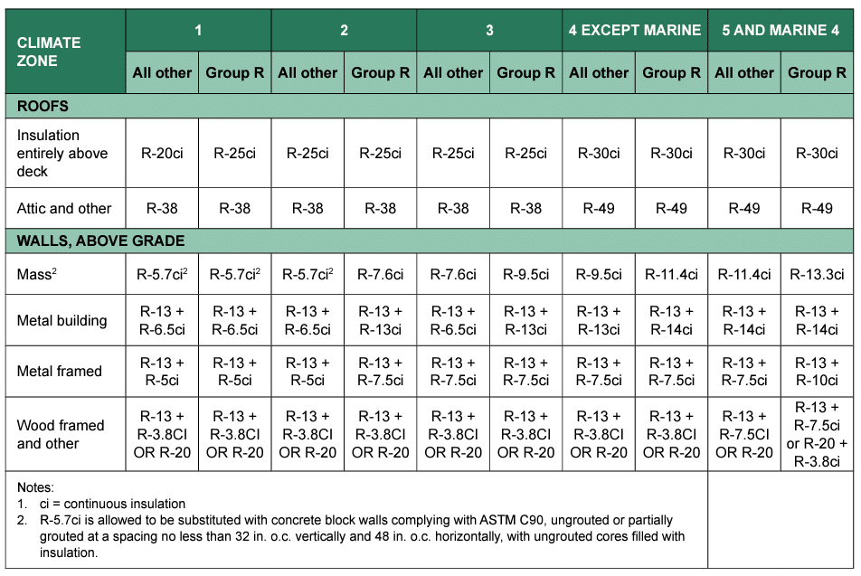
Of the 3 compliance methods, the prescriptive method is the easiest to apply and perhaps the best recognized. Prescriptive requirements for building envelope elements are listed in table format, with requirements listed separately for each element and climate zone, as shown in Table 1. Table 1 shows that in Chicago (Climate Zone 5), a flat roofed building (other than Group R) must have R30 continuous insulation and masonry walls (listed as ‘Mass’) must have R11.4 continuous insulation to comply with this table. This table is often the sources of the misconception that these elements must have continuous insulation in order to comply with the IECC.

Using this prescriptive table, the requirements for individual elements are independent of each other. In Climate Zone 5, if the mass wall has R14 insulation and the roof has R20, the building cannot comply prescriptively based on R-values. Hence, although using the prescriptive tables is very straightforward, it is also very limiting in terms of design flexibility.

IECC Table C402.1.3 is also misinterpreted as not permitting insulation within the hollow cells of a single-wythe concrete masonry assembly for energy compliance. Although concrete masonry with integral insulation cannot comply under the Table C402.1.3 requirement for continuous insulation because the webs of the masonry units interrupt the insulation, the IECC provides an additional prescriptive option in Table C402.1.4 based on the overall U-Factor of the wall assembly. (The U-Factor is the inverse of R-Value, i.e. U = 1/R and R = 1/U).

For compliance with IECC Table C402.1.4, the U-Factor of the wall assembly must meet the prescriptive U-Factor requirement instead of the insulation meeting the prescrip- tive R-Value of IECC Table C402.1.3. For example, the mass wall U-Factor requirement for Chicago (Climate Zone 5) is U0.078, which corresponds to an R-Value of 12.8. As long as the wall as a whole (not the insulation alone) meets the U0.078/R12.8 requirements, the wall complies with the IECC in Climate Zone 5. Although not as flexible as the trade-off or whole building analysis compliance options, the prescriptive U-Factor option of the IECC often provides additional flexibility over the prescriptive R-Value approach.

Table 1—Excerpt from 2021 IECC Table C402.1.3 Showing Prescriptive Wall and Roof R-Value Requirements1

Table 2—Excerpt from 2021 IECC Table C402.1.4 Showing Prescriptive Mass Wall U-Factor Requirements by Climate Zone for Buildings Other than Group R

Additional discussion on thermal efficiency and code compliance options for concrete masonry construction is provided in References 2-5.

REFERENCES
  1. 2021 International Energy Conservation Code (IECC), International Code Council, www.iccsafe.org.
  2. “R-Values of Multi-Wythe Concrete Masonry Walls”, CMHA TEK 06-01C, Concrete Masonry & Hardscapes Association, masonryandhardscapes.org, 2013.
  3. “R-Values and U-Factors of Single Wythe Concrete Masonry Walls”, CMHA TEK 06-02C, Concrete Masonry & Hardscapes Association, masonryandhardscapes.org, 2013.
  4. “Thermal Catalog of Concrete Masonry Assemblies, 2nd Edition”, CMHA CMU-MAN-004-12, Concrete Masonry & Hardscapes Association, masonryandhardscapes.org, 2012.
  5. “What options are available for complying with the International Energy Conservation Code?”, CMHA CMU-FAQ-009-14, Concrete Masonry & Hardscapes Association, masonryandhardscapes.org, 2014.

What is the Minimum Required Compressive Strength for Concrete Masonry?

Revised 2023

For decades designers have been afforded two methods for qualifying the compressive strength of masonry assemblies. Those two forms of conformance have either been testing prisms (those prisms constructed at the jobsite or prisms removed from existing masonry) to evaluate compressive strength or the Unit Strength Method. The latter is typically the preferred method for many projects due to a relatively quick and easy process with minimal cost implications. While simple and convenient, the unit strength method has long been recognized as the more conservative of the two options. The unit strength method underwent a significant revision for the 2013 version of the Specification for Masonry Structures (TMS 602-13/ACI 530.1-13/ASCE 6-13) and Building Code Requirements for Masonry Structures (TMS 402-13/ACI 530/ASCE 5-13) [1]. This change is also reflected in subsequent versions of TMS 402/602 in 2016 and 2022.

What is the Unit Strength Method?

The unit strength method was developed utilizing compressive strength testing data compiled from research as early as the 1950s up to the 1980s.  Simply put, the resulting method derived from test data determined the overall assembly compressive strength based on the individual unit strength and the type of mortar to be used in design. 

What has changed?

For years the unit strength method table published in TMS 602 had remained unchanged and relied upon the original historical data set.  Realizing the restrictive conservatism in design values, a research project [2] was initiated to compile a new data set reflecting current test methods and material properties. This research in turn was adopted into the 2013 edition of TMS 402/602 and is contained in the more recent 2016 and 2022 versions. The unit strength method from the 2022 TMS 402 is shown in Table 1, which illustrates the correlation between unit compressive strength, mortar type, and assembly compressive strength.

Increasing the final design strength of masonry assemblies has not been the only recent change. In 2014, ASTM C90 was revised to increase the minimum compressive strength of a unit from 1900 psi (13.1 MPa) to 2000 psi (13.8 MPa) that is reflected in C90–22 [3].  When using the recalibrated unit strength table, a concrete masonry unit complying with the minimum requirements of ASTM C90 and laid in Type S or M mortar produces an assembly compressive strength of 2,000 psi (13.8 MPa), which is substantially larger than the historical default minimum of 1,500 psi (10.3 MPa) common in earlier version of the code.

Table 1—Compressive strength of masonry based on the compressive strength of concrete masonry units and type of mortar used in construction (Ref TMS 602)

How will these changes affect me?

With increases to not only unit strength and overall assembly compressive strength, concrete masonry can remain positioned competitively amongst other building materials used in building construction. Production of units remains virtually unchanged. The increase in strengths stem from reducing uncertainty in the data used to develop these design values and verifying strengths already present in contemporary concrete masonry units.

References
  1. Building Code Requirements and Specification for Masonry Structures, TMS 402 and TMS 602, The Masonry Society 2013, 2016, and 2022 versions, www.masonrysociety.org.
  2. Recalibration of the Unit Strength Method for Verifying Compliance with the Specified Compressive Strength of Concrete Masonry, MR37, National Concrete Masonry Association, 2012. 
  3. Standard Specification for Loadbearing Concrete Masonry Units, ASTM C90-22. ASTM International, 2022, www.astm.org.

Disclaimer: The content of this CMHA FAQ is intended for use only as a guideline and is made available “as is.” It is not intended for use or reliance upon as an industry standard, certification or as a specification. CMHA and those companies disseminating the technical information contained in the FAQ make no promises, representations or warranties of any kind, expressed or implied, as to the accuracy or completeness of content contained in the FAQ and disclaim any liability for damages or injuries resulting from the use or reliance upon the content of FAQ. Professional assistance should be sought with respect to the design, specifications, and construction of each project.

Can You Place Vegetation on Top of Segmental Retaining Walls?

Revised 2024

Yes. Segmental Retaining Walls (SRWs) are commonly combined with vegetation above the wall to reduce erosion and for aesthetic reasons. The trees and shrubs placed above the SRW have to be selected and placed to not affect the wall alignment or the wall performance, and survive on the wall. When selecting the trees and shrubs, and deciding their placement on the wall, keep the following guidelines in mind. These guidelines are based on industry recommendations (see FIGURES 1 AND 2):

  • The tree and shrub size, type, and location should be selected based on the size of the mature plant so it does not impact the wall negatively.
  • The spacing between trees and shrubs should be the larger of the minimum recommended spacing for the plant variety 4 times the diameter of the root ball or 5 ft (1.5 m), measured from center to center in all directions.
  • Trees and shrubs should be staggered behind the SRW face. 
  • There are no limitations for the type/number of shrubs or the height of the tree to use.
  • The plants are recommended to be placed away from the wall face so the dripline of the mature trees or shrubs (edge of the foliage) is not hanging passed the wall face.
  • Maintain a minimum distance of 5 ft (1.5 m) between the edge of the root ball and the face of the wall.
  • Use temporary irrigation to establish the vegetation (this doesn’t apply to vegetated SRW faces).
  • If permanent irrigation is installed consult with the design engineer.
  • Between terrace walls, restrict the vegetation to shrubs unless there is enough space to follow the recommendation for trees.
  • Vegetation in the front of the wall must also be planned to not undermine the SRW or affect the stability of the wall.

With proper planning and scheduling sonotubes or concrete rings can be placed during construction as placeholders for the trees. The size and placement have to follow the recommendations above.

If trees are planted after the construction of the wall, it is advisable to only cut the top two (2) layers of geogrid, manually excavate the first 24 in. (610 mm) of soil, and use augers only if needed, after hand excavation of the top 24 in. (610 mm).

If trees are placed closely together and cutting of geogrid becomes excessive, consult with your wall design engineer.

Does the Building Code Address Cleaning of Newly Constructed Masonry?

Revised 2018

Yes. Article 3.8 of TMS 602-13 [1], which is referenced by both the International Building Code and International Residential Code, states: Clean exposed masonry surfaces of stains, efflorescence, mortar and grout droppings, and debris using methods that do not damage the masonry.

While the building code does not require all newly constructed masonry to be cleaned (for example, an unexposed backup assembly isn’t typically cleaned by default), it does require that approved cleaning procedures be stipulated and implemented when required. Further, because the project conditions, masonry materials, and care in construction can all vary from one project to another, so should the aggressiveness of cleaning efforts. Best practices suggest using the least aggressive cleaning process that achieves the desired result and demonstrating these cleaning procedures on the project’s sample panel to ensure the final outcome is satisfactory. Additional discussion on cleaning options and procedures is available in CMHA TEK 08-04A [2].

Cleaning can include varying degrees of effort, including: simple hand cleaning using brushes and trowels, pressure washing, chemical cleaning, and abrasive cleaning. Additional considerations are reviewed in more detail in the following discussion.

GROUTED MASONRY CONSTRUCTION

All mortared masonry construction has the potential for mortar smears to develop on the surface of the masonry. When grout is introduced into the masonry assembly, the potential for cleaning increases. Grout can not only be dropped onto the surface of the masonry when being placed, but because of the highly fluid nature of masonry grout, it has the potential of leaking through the face of the masonry or through holes in the mortar joints and running down the face of the assembly. This likelihood of leakage can increase when the concrete masonry units and mortar contain integral water repellents. Because the plastic grout is under extreme head pressure when first placed and consolidated, the resulting pore structure of units containing integral water repellents may force the grout through small pin holes in the face of the units or through small defects or hairline cracks in the mortar. For these reasons, some degree of cleaning should be planned for with all exposed, grouted concrete masonry construction.

TIMING OF CLEANING

The success of cleaning a newly construction concrete masonry assembly can be driven as much by the timing of when the cleaning occurs as the cleaning procedures used. For example, attempting to remove fresh mortar droppings from the surface of the masonry is likely to result in smearing that requires additional cleaning efforts. Allowing the mortar to slightly set before removing reduces the likelihood of smears occurring. In the case of grout leakage through small pinholes in water repellent CMU or small mortar defects, in warm, sunny weather periodically spraying the wall down with low pressure water within hours after grouting can often wash off much of the grout leaks and make final cleaning of the building easier. Be aware, though, that allowing the mortar and grout to fully cure on the surface of the assembly will require much more aggressive cleaning procedures to be used as it will be more difficult to remove these materials once they have fully hardened. Additional discussion is available in CMHA TEK 0308A [3] and TEK 08-02A [4].

REFERENCES
  1. Specification for Masonry Structures, TMS 602-13, The Masonry Society, 2013.
  2. Cleaning Concrete Masonry, TEK 08-04A, CMHA, 2005.
  3. Concrete Masonry Construction, TEK 03-08A, CMHA, 2001.
  4. Removal of Stains from Concrete Masonry, TEK 08-02A, CMHA, 2005.

Why Did the 2013 TMS 402 Standard Introduce a Design Check for Web Shear Stresses?

Revised 2023

Historically, the shear stresses in the webs connecting the face shells of a concrete masonry unit were not explicitly checked as part of routine design practice. Instead, ASTM C90, Standard Specification for Loadbearing Concrete Masonry Units [1], prescriptively required a minimum amount of web such that this design check was unnecessary. In 2011, however, ASTM C90 was modified to allow concrete masonry units with alternative web configurations (such as single or double-open-ended units); thus prompting the new design check – but only for unreinforced/ungrouted masonry assemblies. Once grout is added to the cells of a unit, the presence of the grout more than compensates for any reduction in the web area. The design check discussed herein was first introduced into TMS 402 in the 2013 version [2]. This FAQ discusses this check in relation to the 2022 version of TMS 402 [3].

DESIGN CHECKS

Both the allowable stress and strength design provisions (Chapters 8 and 9, respectively of TMS 402 -22 require a check on web shear stress for unreinforced masonry construction.

For allowable stress design, the shear stresses in the webs of a concrete masonry assembly are calculated in accordance with Section 8.2.6.1 as follows:

Where:
fv   = calculated shear stress in masonry, lb/in.2 (MPa)
In   = moment of inertia of net cross-sectional area of a member, in.4 (mm4)
Q    = first moment about the centroid of an area between the extreme fiber and the plane at which the shear stress is being calculated, in.³ (mm³)
V    = shear force, lb. (N)
b     = width of section for which shear stresses are being calculated (e.g., web thickness), in. (mm)

TMS 402/ACI 530/ASCE 5 further stipulates that the calculated shear stresses in the webs cannot exceed the following:

Where:
Fv    = allowable shear stress, lb/in.2 (MPa)
f’m  = specified compressive strength of the masonry, lb/in.2 (MPa)

Similarly, Section 9.2.6.2 contains the following limits for web shear stresses in assemblies designed using the strength design provisions:

Where:
= strength-reduction factor taken equal to 0.80
Anv = net shear area, in.2 (mm2)
Vn = nominal shear strength, lb (N)

SAMPLE CALCULATIONS

Consider, for example, a standard 8 in. (203 mm) wide concrete masonry assembly measuring 18 feet (5.48 m) in height with a specified compressive strength of 2,000 lb/in.2 (13.8 MPa). If this wall were subjected to a 25 lb/ft2 (1197 Pa) out-of-plane design pressure, the resulting maximum shear would be 225 lb/ ft (3,283 N/m). Correspondingly, the critical shear carried by the webs of individual units within the assembly would be:

While the actual unit configuration may vary, if we assume this assembly was constructed using double- open-ended units (H-block) similar to that below, then the resulting cross-sectional properties for this unit would be (assuming standard in. (10 mm) mortar joints are used):

These section properties are determined about the centroid of the unit cross-section, which also corresponds to the location where the shear stresses across the web will be the largest. Using the allowable stress design provisions, the resulting critical shear stress is:

We then compare the shear stresses across the unit with the allowable shear stresses. In reality one could argue that the compressive strength of the unit should be used as it is solely the web material that is resisting the shear stresses; however, for simplicity we’ll conservatively apply the specified assembly compressive strength.

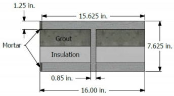
While TMS 402 is not clear when applying the new web shear design checks on assemblies containing non-structural materials, such as insulation, when the material does not contribute to the strength of the assembly, the calculation would proceed exactly as above simply neglecting the presence of the non-structural material. If, however, the assembly contained both grout and insulation, then the section properties of the unit would need to be adjusted to account for the presence of the grout. Further, in cases where the insulation interrupts the bond between the face shell and the grout, as illustrated in the assembly configuration below, the web shear stresses should be checked, regardless of whether the assembly was reinforced or not.

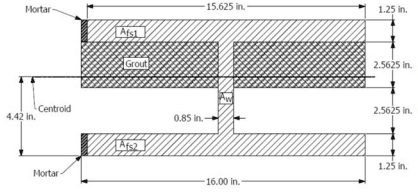
Assuming the grout and insulation each fill one-half of each cell in the assembly, we first determine the new centroid of the cross-section:

Therefore, the resulting location of the new centroid of the cross-section, C, is:

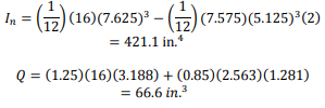
Using conventional parallel axis theorem, the resulting moment of inertia of the composite unit/grout cross section is then:

Next we’ll need to determine Q for the location where the shear stresses are the largest. In this example it will be nearest to the center of the cross section of the unit where the web of the unit is the thinnest as follows:

The resulting critical shear stress is:

Which is still less than the allowable shear stress of 67 lb/in.2 (0.46 MPa).

While this example illustrates the application of the web shear check using the allowable stress design provisions, the strength design shear check proceeds similarly using the nominal shear strength of the assembly.

In reality one could generally assess by inspection that if the assembly without grout was able to safely resist the resulting web shear stresses then the introduction of grout into the assembly would not weaken the assembly’s ability to transfer shear stresses; thus considerably simplifying the design. In cases where the grout-to-face shell bond is uninterrupted by insulation or other non-structural materials located within the cells of the concrete masonry assembly, the provisions of TMS 402 would not require web shear stresses to be checked, as the presence of the grout compensates for any reduction in the web area connecting the face shells.

References

  1. ASTM C90, 2015, Standard Specification for Loadbearing Concrete Masonry Units, ASTM International, West Conshohocken, PA, 2015.
  2. Building Code Requirements for Masonry Structures, TMS 402/ACI 530/ASCE 5, The Masonry Society, Longmont, CO, 2013.

Are RILEM Tubes an Effective Method of Evaluating the Water Repellent Characteristics of CMU?

Revised 2015

No. The “RILEM” Tube Test was originally developed to provide an indication of the initial absorptive characteristics of stone masonry. These values could be correlated to the deterioration rates of stones in various areas of a stone masonry structure and to evaluate the effectiveness of remediation techniques. Today the RILEM Tube Test is often used (or misused) to assess the water repellent characteristics of a concrete masonry assembly, usually after a report of water penetration. There can be several reasons why a masonry wall leaks, but using the RILEM Tube Test to assess absorptive characteristics of individual units to determine the cause of the water penetration is largely ineffective and the results often misinterpreted. This misinterpretation can detract from the effort to determine and fix the actual root cause(s) of the masonry wall leaks.

RILEM TUBE AND TEST METHOD DESCRIPTION

The RILEM Tube Test was developed in the late 1970’s by RILEM (a European group similar to ASTM) for quantifying the amount water absorbed and forced into the surface of masonry stone. The test utilizes a straight or L-shaped hollow tube (see Figures 1 and 2). The straight tube is for horizontal surfaces while the L-shaped tube is for vertical surfaces. The large opening of the tube is adhered to the stone’s surface using putty or rope caulk. Water is then added to the tube and monitored over time. As the water drops an absorption rate (volume of water absorbed over time) can be determined.

Figure 1— RILEM Tube on Vertical Surface

Figure 2— RILEM Tube on Horizontal Surface

RILEM TUBE LIMITATIONS

While the RILEM tube can be visually impactful, the method only quantifies water absorbed and adsorbed by a stone or masonry unit’s surface and not the volume of water penetrating through a masonry assembly.

One of the greatest drawbacks to using a RILEM tube is that the area in contact with the surface measures only 0.88 in.2 (5.7 cm2), which is quite small. Due to the small area there is inherent variability in the test. A study conducted at the University of Wyoming concluded that 1,665 tests would need to be conducted for every 12 ft2 (1.11 m2) of wall surface being evaluated in order to achieve a sample error of 10% or less [8]. Hence, drawing any conclusions about the water penetration characteristics of an entire wall assembly based on 50, 100, or even 500 tests can be speculative at best.

The RILEM Tube Test can be useful when evaluating the effectiveness of a remediation procedure, such as the application of a surface coating, by measuring the surface absorption characteristics before and after the treatment. However, care and insight must be used when interpreting the results.

RECOMMENDED METHODS FOR EVALUATING WATER REPELLENCY

When CMU are specified to have water repellent characteristics, the industry recommends following CMHA TEK 19-07, which contains requirements for this type of CMU [1]. These requirements are based on the use of three test methods, and CMHA TEK 19-07 contains performance requirements for each:

  • Water Droplet or Water Stream Test [2] – this is a quick field method where water beads are placed on a unit in a horizontal position, or a stream of water is sprayed onto a constructed wall. If the bead stays on the surface (or if the water stream visibly runs down the wall) the unit is considered to have water repellent characteristics. It is important to note that exposure can degrade the repellency characteristics at the surface of the unit, so if the units do not pass this test they should be taken to the laboratory for further evaluation.
  • Spray Bar Test [3] – in this test, a unit is subjected to a constant stream of water over the surface of the face shell for four hours. After that time, the inside of the exposed face shell is observed and the amount of dampness is measured. This test is effective in evaluating overall water repellency, as well as detecting the presence of interconnected voids in the concrete matrix.
  • Water Uptake Test [4] – in this test, a coupon sample is taken from a CMU and partially submerged in water. The amount of water the coupon absorbs over time is measured. This test evaluates the capillary suction of a CMU.

These tests were developed for evaluating the characteristics of the CMU independent of the rest of the concrete masonry assembly. Several laboratory and field methods ([5], [6], [7]) have been developed by ASTM for evaluating the water penetration characteristics of masonry wall assemblies. The CMHA methods are effective in evaluating the water repellency characteristics of the CMU, and the ASTM methods listed can evaluate either the performance of the assembly overall or the drainage system within a masonry assembly. In many cases, however, these methods may not uncover the underlying problem of why a building is leaking. Such issues many times are tied to causes unrelated to the masonry assembly (such as unprotected masonry during construction, connections at a roof, or improper detailing of flashing).

REFERENCES
  1. Characteristics of Concrete Masonry Units with Integral Water Repellent, TEK 19-07, CMHA, 2008.
  2. CMU-WR1, Standard Test Methods for Water Stream and Water Droplet Tests of Concrete Masonry Units, CMHA, 2009.
  3. CMU-WR2, Standard Test Method for Spray Bar Test of Concrete Masonry Units, CMHA, 2009.
  4. CMU-WR3, Standard Test Method for Assessing Water Uptake Potential of Concrete Masonry Units, CMHA, 2009.
  5. ASTM C1601-14a, Standard Test Method for Field Determination of Water Penetration of Masonry Wall Surfaces, ASTM International, West Conshohocken, PA, 2014, www.astm.org.
  6. ASTM C1715-10, Standard Test Method for Evaluation of Water Leakage Performance of Masonry Wall Drainage Systems, ASTM International, www.astm.org.
  7. ASTM E514/E514M-14a, Standard Test Method for Water Penetration and Leakage Through Masonry, ASTM International, www.astm.org.
  8. Effects of Pressure on Water Penetration in Brick Masonry, S. Roller, M.S. Thesis, Department of Civil and Architectural Engineering, University of Wyoming, Laramie, WY, 1994.