Resources

What Is the Minimum Required Compressive Strength for Masonry Mortars?

Revised 2014

Simply put, there are no minimum compressive strength requirements for field-batched masonry mortar in any current ASTM standard or building code provision. There are, however, minimum compressive strength requirements for masonry mortars prepared and tested in the laboratory in accordance with ASTM C270.

The two primary ASTM standards covering masonry mortar testing include:

  • ASTM C270 Standard Specification for Mortar for Unit Masonry
  • ASTM C780 Standard Test Method for Preconstruction and Construction Evaluation of Mortars for Plain and Reinforced Unit Masonry

Section 5.2.6 of ASTM C 780 states: 5.2.6 Compressive strength testing of molded mortar cylinders and cubes allows establishment of the strength developing characteristics of the mortar. The measured strength is dependent upon the mortar water content at the time of set, along with other factors, and reflects the general strength that would be attained by the mortar in the masonry. The measured value shall not, however, be construed as being representative of the actual strength of the mortar in the masonry. Due to specimen shapes—cylinders versus cubes—the strength results between the two different-shaped specimens of identical mortar will vary.

Similarly, Section 3 of ASTM C 270 states:

3. Specification Limitations

3.1 Specification C 270 is not a specification to determine mortar strengths through field testing.

3.2 Laboratory testing of mortar to ensure compliance with the property specification requirements of this specification shall be performed in accordance with 5.3. The property specification of this standard applies to mortar mixed to a specific flow in the laboratory.

3.3 The compressive strength values resulting from field tested mortars do not represent the compressive strength of mortar as tested in the laboratory nor that of the mortar in the wall. Physical properties of field sampled mortar shall not be used to determine compliance to this specification and are not intended as criteria to determine the acceptance or rejection of the mortar (see Section 8).

In practice, the compressive strength requirements for masonry mortar contained in ASTM C270 are often misapplied to field-batched mortar. As stated in Section 3 of C 270, the compressive strength values in that standard are only to be applied to laboratory prepared mortar. In part, the intent of compressive strength testing of field-batched mortar in accordance with ASTM C780 is to document the consistency of the mortar properties throughout a project. As the title of ASTM C780 implies, testing in accordance with C780 applies to both preconstruction and construction testing of masonry mortars. When the property specification (i.e., compressive strength) of ASTM C270 is used to specify a mortar for a project, preconstruction evaluation of the mortar would allow for the mortar to be batched using both standardized laboratory procedures and field methods to compare and evaluate the physical properties resulting from each mortar set.

Laboratory batching of masonry mortar is not intended to simulate field-batched mortar, but instead to provide a standardized means of comparing the influence of varying proportions of mortars materials, the addition of an admixture, and similar variables. In addition to the differences in batching procedures between laboratory- and field-prepared mortars, the amount of water added to each mix can differ significantly. In the field, additional water is intentionally added to the mortar mix so that when the plastic mortar is placed onto a masonry unit, the water absorbed from the mortar by the unit will not ‘dryout’ the mortar before it has a chance to cure. When this field mortar is selected for compressive strength testing and placed in a non-absorbent mold, the water-to-cement ratio remains artificially elevated during curing, unlike the mortar placed on masonry units, which has had the free water removed due to unit absorption. Laboratory mortar batched, conversely, is intentionally batched to a low water-to-cement ratio to simulate the absorption characteristics of masonry units. When molded into compression specimens, the laboratory mortar will always have a higher compressive strength compared to field mortar as a result of the lower water-to-cement ratio.

ASTM has recently published ASTM C1586 Guide for Quality Assurance of Mortar that provides additional guidance regarding the interpretation of testing values for field sampled mortars and explains why the compressive strength of sampled mortar, either from the laboratory or from the field, is not considered to be equal to the compressive strength of the mortar in the wall. At this time, there are no standardized means of directly evaluating the compressive strength of cured mortar samples taken from a wall.
What Is the Bullet/Ballistic Resistance of Concrete Masonry?

Revised 2017

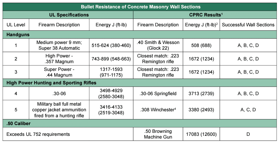
The actual resistance of concrete masonry assemblies to high velocity projectiles such as bullets varies considerably depending on the details of the assembly and the type and energy of the projectile. While many tests have been conducted through the years documenting the ballistic resistance of concrete masonry construction, much of this research is not available in the public domain. The most current published comprehensive study was conducted in Canada by the Canadian Masonry Research Institute and the Royal Canadian Mounted Police as reported in Resistance of Exterior Walls to High Velocity Projectiles [1]. A key conclusion of this report noted that: “Walls finished with either a clay brick or concrete brick veneer prevented all but the 0.50 Browning from complete penetration of the wall assembly.”

Although the firearms and bullets used in this study do not exactly match Underwriters Laboratories bullet resistance levels under UL 752, Standard for Bullet-Resisting Equipment [2], (the standard often cited for bullet resistance), a comparison can be made by adjusting for the impact energy level as shown in the table below.

Before the Canadian study, most published ballistic testing on concrete masonry walls was carried out during World War II to make sure that adequate protection was provided for transformers, switching stations, and similar installations subject to sabotage. Recommended constructions for bullet resistance are 8 in. (203 mm) solid or grouted concrete masonry walls or 12 in. (305 mm) hollow units with sand-filled cores. Both walls provided equal protection under test conditions. In no case did bullets penetrate the opposite face shell of the masonry when tested with high-powered rifles, revolvers, and machine guns. Glass unit masonry products have been tested for bullet resistance. Solid glass unit masonry (8 x 8 x 3 in. thick) (203 x 203 x 76 mm) achieved UL Levels 1, 2, and 6. Hollow glass block (8 x 8 x 4 in. thick) (203 x 203 x 102 mm) with a thickened, 3/4 in. (19 mm), face shell achieved a Level 1 rating. These ratings apply to glass unit masonry panels at least three units high by three units wide framed on all four sides and laid with Type S mortar.

REFERENCES
  1. “Resistance of Exterior Walls to High Velocity Projectiles”, TR-03-2002, Canadian Police Research Centre, 2002. https://pubs.drdc-rddc.gc.ca/BASIS/pcandid/www/engpub/ DDW?W%3DSYSNUM=529986
  2. “Standard for Bullet-Resisting Equipment”, UL 752, Underwriters Laboratory, 2009. www.ul.com

Notes:

  1. Source: Reference 1.
  2. Adjusted for difference in distance to target per UL 752 of 15 ft (4.6 m) and Ref.1 of 82.0 ft (25 m).
  3. Wall section descriptions:
    • A – Concrete masonry or clay masonry brick veneer with a nominal thickness of 90 mm (4 in.).
    • B – 150 mm (6 in.) nominal hollow concrete masonry units.
    • C – 150 mm (6 in.) nominal split-face hollow architectural concrete masonry units
    • D – Multi-wythe wall with either 90 mm (4 in.) nominal clay or concrete masonry brick with 150 mm (6 in.) nominal hollow concrete masonry unit backup.
  4. The muzzle energy exceeds UL minimum requirement; however, when adjustment is made for distance, the energy falls just below the UL minimum. The bullet stopped within the veneer however, and did not penetrate the backup.

What Is the Difference Between a “Cinder Block” and a “Concrete Block”?

Revised 2014

Concrete masonry units are colloquially known by many names, most predominately “concrete block”, “cinder block”, “CMU”, or simply “block”. Related concrete products, manufactured using similar materials and production methods but used in different applications, include products such as concrete pavers, segmental retaining wall units, and articulating concrete block.

There are many, many opinions and theories that have been proposed through the years (and continue to circulate) that attempt to explain the difference between a “concrete block” and “cinder block”. The reality, however, is that these masonry units are essentially the same product produced with the same three basic constituent materials: water, cement, and aggregate.

In the early years of the 20th century as concrete masonry units were beginning to be used with more frequency, producers were looking for ways to reduce the weight of the units to facilitate their use in construction and increase mason productivity. To reduce the unit weight, many producers (but not all) incorporated cinders into their block as an alternative to conventional stone aggregate. Cinders, which include both waste by-products of coal combustion as well as volcanic cinders, were an ideal, cost-effective, lightweight aggregate that was readily available in many areas of the country. Soon after, the terms “cinder” and “block” were perpetually linked. The use of waste by-products such as coal cinders effectively made concrete masonry the first construction material to adopt green, sustainable practices; a century before it was fashionable to do so.

The practice of incorporating coal combustion cinders (as well as other waste by-products) into concrete masonry units continues today. Yet, using cinder aggregates as a lightweight alternative to stone and gravel aggregate may have inadvertently led to another common misconception regarding the term cinder block: that cinder block are lighter (have a lower density) compared to concrete masonry units. While it is true that a concrete block manufactured with cinders will tend to have a lower density compared to a concrete block manufactured with stone aggregate, there are many other lightweight aggregate types (both natural and man-made) that are commonly used in block production. As such, the density of a block is not an indication of whether it has been manufactured with or without cinders.

For many the term cinder block is associated with older concrete masonry; presumably manufactured during the first half of the 20th century. As previously discussed, cinders (both volcanic and coal combustion by-products) continue to be used in block production today – as such, there is no differentiating a concrete block from a cinder block based upon its age.

What has changed over the past 100 years is the technology used today to produce concrete masonry results in a consistently high-quality product with uniform properties. Likewise, codes and standards have evolved through the years to comprehensively address minimum physical requirements for concrete masonry to ensure the long-term durability and performance of these products. Consequently, some associate cinder block with inconsistent or poor quality units produced in early 20th century, which has led some to believe that cinder block are not permitted to be used to construct buildings today. The reality is that all concrete masonry units used in construction must meet minimum requirements established by building codes, regardless of whether they contain cinders or not. Further, regardless of whether you are studying a newly constructed building or a 100 year old foundation – those concrete units are concrete masonry units, CMU, concrete block…or if you prefer, cinder block – although it is nearly impossible to tell visually if a given unit contains actual cinders.

The introduction of new manufacturing technologies, alternative or non-traditional constituent materials, unique unit configurations, and ever-expanding market-driven applications has in recent years pushed the boundaries of what has conventionally been known as a “concrete masonry unit” into areas where some, or most, would no longer associate a given product with historical definitions for these units.

Some of the material differences are small, such as units that are manufactured with small amounts of recycled or byproduct materials that are similar in nature to constituent materials traditionally used in production. Other differences are more substantial, such as compressed earth/clay products whose visual appearance mimics that of concrete masonry but with few other similarities. The question that results is: “At what point are the characteristics of a concrete masonry unit changed so significantly that it evolves into a different type of product entirely?”

While on the surface establishing specific guidance for defining a concrete masonry unit may seem trivial or pedantic, it can have multiple important consequences. One such important consideration is ensuring that building code requirements and design provisions are applied to the construction material for which they were intended – and not extrapolated to other products that share similar attributes or applications, but lack the characteristics to perform similarly. Nevertheless, even contemporary codes and standards are vague in their definition of a concrete masonry unit.

Chapter 21 of the 2009 International Building Code contains the following definitions:

Concrete Masonry Unit—A building unit or block larger in size than 12 inches by 4 inches by 4 inches (305 mm by 102 mm by 102 mm) made of cement and suitable aggregates.

Concrete Brick—A masonry unit having the approximate shape of a rectangular prism and composed of inert aggregate particles embedded in a hardened cementitious matrix.

Masonry—A built-up construction or combination of building units or materials of clay, shale, concrete, glass, gypsum, stone or other approved units bonded together with or without mortar or grout or other accepted methods of joining.

ASTM C1232-09, Standard Terminology of Masonry, contains several definitions that are relevant to this discussion, but does not contain a definition for a generic concrete masonry unit. The introduction of such a definition has been attempted multiple times, but continues to be a point of contention due in part to the broad use of the term.

Concrete Brick, n—a concrete masonry unit made from portland cement, water, and suitable aggregates, with or without the inclusion of other materials. See Specification C 55.

Manufactured Masonry Unit, n—a manmade noncombustible building product intended to be laid by hand and joined by mortar, grout, or other methods of joining.

Masonry, n—the type of construction made up of masonry units laid with mortar, grout, or other methods of joining.

CMHA TEK 01-04, Glossary of Concrete Masonry Terms, contains the following definitions:

Block—A solid or hollow unit larger than brick-sized units. (See also “Concrete block, concrete masonry unit, manufactured masonry unit”)

Brick—A solid or hollow manufactured masonry unit of either concrete, clay or stone.

Concrete block—A hollow or solid concrete masonry unit. Larger in size than a concrete brick.

Concrete brick—A concrete hollow or solid unit smaller in size than a concrete block.

Concrete masonry unit—Hollow or solid masonry unit, manufactured using low frequency, high amplitude vibration to consolidate concrete of stiff or extremely dry consistency.

Manufactured masonry unit—A man-made noncombustible building product intended to be laid by hand and joined by mortar, grout or other methods.

Masonry—An assemblage of masonry units, joined with mortar, grout or other accepted methods.

Historically, a more informal classification of a concrete masonry unit has also considered the following criteria:

  • Manufactured on high-speed equipment that use a combination of compression and vibration to consolidate a mix into a mold;
  • Manufactured using a no-slump, or nearly no-slump, concrete mix (also referred to as dry-cast concrete);
  • Manufactured using inert (including chemically nonreactive), inorganic constituent aggregates, such as those meeting the requirements of ASTM C331 for lightweight aggregates or ASTM C33 for normal weight aggregates;
  • Manufactured using conventional cementitious materials including cements meeting the requirements of ASTM C150, C595, C618, C989, or C1157 that, with the addition of water, chemically hydrate to permanently bind the constituent materials together;
    • Produced using other constituent materials, such as admixtures or pigments, which have been established by test or performance to be suitable for use in the production of such units without detrimental impact on the use or performance of the resulting construction.
  • Laid or placed, typically by hand, with or without the use of mortar, grout, or supplemental reinforcement;
  • Used in building, non-building, and hardscape applications; and
  • Used in loadbearing or non-loadbearing applications.

How is the Fire Resistance of a Concrete Masonry Assembly Calculated When Using Unconventional Aggregates?

Revised 2023

The International Building Code (IBC) outlines multiple options for documenting the fire rating of concrete masonry assemblies, including:

  • Third party listing services, such as Underwriters Laboratory;
  • Full-scale testing in accordance with ASTM E119;
  • Standardized calculation procedures, such as ACI/TMS 216.1; and
  • Alternative means approved by the building official.

Additional information on determining the fire resistance rating of concrete masonry products is available in CMHA TEK 0701D, Fire Resistance Rating of Concrete Masonry Assemblies.

In recent years manufacturers of concrete masonry products have been exploring the use of alternative materials in the production of concrete masonry units. Some of these materials have not been evaluated using standardized fire resistance test methods or have been evaluated only to a limited degree. Such unconventional materials, which are typically used as a replacement for conventional aggregates, may not be covered within existing codes and standards due to their novelty or proprietary nature.

While test methods such as ASTM E119, Standard Test Methods for Fire Tests of Building Construction and Materials, defines procedures for evaluating the fire resistance properties of concrete masonry assemblies, including those constructed using unconventional constituent materials, there has historically been no defined procedure for applying the results of ASTM E119 testing to standardized calculation procedures available through ACI/TMS 216.1, Standard Method for Determining Fire Resistance of Concrete and Masonry Construction Assemblies.

In general, when applying the fire resistance calculation procedure of ACI/TMS 216.1 to products manufactured using non-listed aggregate types, at least two full-scale ASTM E119 tests must be conducted on assemblies containing the unconventional material. Based on the results of the full-scale testing, an expression can be developed in accordance with this industry practice that permits the fire resistance of units produced with such aggregates to be calculated for interpolated values of equivalent thickness and proportion of non-listed aggregate.

How Can the Bearing Area of a Concrete Masonry Prism Removed From Existing Construction Be Determined?

Revised 2014

Prisms are saw-cut from existing concrete masonry for a variety of reasons, and correctly determining the compressive strength is essential to applying the test results. In order to calculate the compressive strength, the minimum bearing area for the prism must be determined. Because of varying mortar bedding options, it can at time be difficult to calculate the bearing area accurately.

Within ASTM C1314-11, Standard Test Method for Compressive Strength of Masonry Prisms, Section 8.2.2 states in part “Net area for prisms obtained from field-removed masonry specimens is considered to be minimum bearing area. If prisms are not of uniform length or width throughout the height of the specimen, or if mortar surfaces are not fully bedded, use professional judgment to determine the minimum bearing area that exists for the prism at whatever location this occurs.”

Further, Note 7 of C1314-11 states “While constructed prisms are required to be fully-bedded with mortar, prisms obtained from field-removed masonry specimens, particularly for hollow masonry, will often have only the face shells of the hollow units mortared. For such prisms, if any mortar on the top and bottom bearing surfaces of the prisms are removed to result in full bearing across the unit cross-section, the minimum crosssection will typically occur at an intermediate mortar bed joint. For face shell bedded sections, multiplying the measured length of the prism at the bed joint location by the sum of the face shell thicknesses can be an effective method for determining minimum net bearing area. Because the face shells of hollow units are often tapered, the thickness of the face shell above the mortar bed joint and below the mortar bed joint may differ. In such a case, use the least face shell thickness of the two in the calculation. Obtaining access to measure face shell thickness is often difficult or impossible. Measurements of similar cross-sections from representative units or other parts of the prism is an option as is performing measurements after testing is performed. Refer to Test Methods C67 and C140 for recommended methods of measuring face shell thickness.”

While a method for accurately determining bearing area cannot cover all possible configurations, there are several there are some considerations that can be used to assist in determining the correct net area.

  1. When prisms are solidly grouted – the net bearing area can be calculated as the length multiplied by the width of the prism.
  2. When prisms are hollow with full mortar beds – the net bearing area can be determined by testing companion concrete masonry units with the same configuration in accordance with ASTM C140-11, Standard Test Methods for Sampling and Testing Concrete Masonry Units and Related Units. It is important to remember that when this method is used for half-length prisms, the companion CMU must be saw-cut to the same configuration as well.
  3. When prisms are hollow with face shell bedded mortar only – the net bearing area can be determined as the sum area of the face shells of the units used. The face shell thickness can be determined using the procedures contained in ASTM C140-11. Once the face shell thickness is known, the bearing area can be determined using the following equation:
    • Net Bearing Area (in2) = 2 * (FST * L)
      • Where:
        • FST = minimum face shell thickness, in.
        • L = minimum length of prism, in.

What Happened to the Type I/Type II Unit Designation in ASTM C90?

Revised 2014

Prior to 2000, ASTM C90 included two different type designations for concrete masonry units: Type I units were defined as moisture-controlled units; Type II units were defined as non-moisture controlled units. The requirements for these two different unit types were identical in all respects with one exception: the moisture content of the unit at the time of delivery. Historically, ASTM C90 stipulated a maximum moisture content for Type I units at the time of delivery. Conversely, no such moisture content requirements were specified for Type II units. Since 2000, the Type I/Type II unit designations no longer appear in ASTM standards covering concrete masonry units.

In theory, by limiting the moisture content of a concrete masonry unit to a relatively low level (based on the environmental conditions at the job site and the physical properties of the unit) would in turn reduce a unit’s potential drying shrinkage, which in turn would translate to a reduced potential for shrinkage cracks from forming in the masonry assembly. As such, designers that wanted to maximize the distance between control joints, or possibly remove the need for control joints altogether, would specify the use of Type I concrete masonry units. While sound in theory, the effective use of Type I, moisture-controlled units was difficult to implement primarily because the drying shrinkage potential is largely a function of a unit’s moisture content at the time of installation, not the time the unit was delivered to the jobsite.

The phrase “at the time of delivery” contained in ASTM C90 is central to the reason for the removal of moisture-controlled and non-moisture controlled concrete masonry units. Once the concrete masonry units have been delivered to a customer, the producer of the units has lost control over how they will be used or how they will be protected from the environment. Herein lies the disconnect between using ASTM C90 as a manufacturing specification – as it is intended – and using ASTM C90 as a construction specification – for which it is not intended. Because the “time of delivery” rarely coincides with the time of installation, units delivered within the moisture content limitations of a Type I unit may no longer meet these moisture requirements at the time of installation; having potentially been exposed to a myriad of varying environmental conditions during the time between delivery and installation.

As such, a unit that is delivered to the jobsite meeting the requirements for a Type I unit may in fact be a Type II unit at the time of installation, which could compromise critical design assumptions and result in increased potential for shrinkage cracks from forming. To alleviate the confusion and potential misuse of Type I/Type II concrete masonry units, these designations and their associated requirements were removed from ASTM specifications for concrete masonry units. While they are not designated as such with ASTM standards, this action effectively classifies all concrete masonry units as nonmoisture controlled.

One of the most important issues to stress in this discussion is that the removal of the Type I/Type II designation from ASTM C90 has no negative impact the quality of the product being produced or the assembly being constructed. All units must still comply with the requirements for minimum compressive strength, maximum water absorption, maximum variation in dimensions, face shell thickness, web thickness, equivalent web thickness, and maximum linear drying shrinkage exactly as they had before the removal of type designations. Similarly, multiple industry publications have been issued that address the proper methods of spacing and detailing control joints based upon a uniformly and consistently applied set of design criteria, which ensures uniform and consistent quality construction.

More information on ASTM C90 requirements, recommended maximum moisture content at time of placement, crack control, and control joint criteria can be found in the following CMHA TEK:

  • TEK 01-01D, ASTM Specifications for Concrete Masonry Units
  • TEK 03-01C, All-Weather Concrete Masonry Construction
  • TEK 10-02B, Control Joints for Concrete Masonry Walls—Empirical Method
  • TEK 10-03, Control Joints for Concrete Masonry Walls—Alternative Engineered Method

Will Doubling a Wall’s R-Value Double the Energy Efficiency?

Revised 2014

Rarely. Although higher R-Values reduce heat flow through building elements, the R-Values have a diminishing impact on the building envelope energy use as a whole. In other words, it’s important not to automatically equate higher R-Value with improved energy efficiency.

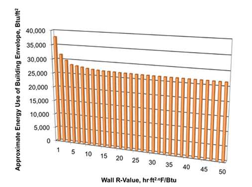
As an example, consider a two-story elementary school in Bowling Green, Kentucky. If this school is built using single wythe concrete masonry walls with integral (cell) insulation resulting in a wall assembly R-Value of 7 hr.ft2.oF/Btu, a simplistic estimate of the building envelope energy use is roughly 27,800 Btu/ft2. If we replace that wall with an R14 wall, the building envelope energy use drops by 2.5%, which is not in proportion to doubling the wall R-value. Figure 1 illustrates the trend: as wall R-value increases, the wall R-value has less and less impact on the building envelope performance. In this example, a wall R-value larger than about R12 no longer has a significant impact on the envelope energy use. At this point, it may make more sense to invest in energy efficiency measures other than wall insulation.

When required, concrete masonry construction can provide walls with high R-values. For overall project economy, however, the industry recommends a parametric analysis similar to that shown in Figure 1 to determine appropriate insulation levels for the building envelope that provide a meaningful return on the initial investment.

Figure 1— Building Energy Use For Varying Wall R-Value

Figure 1 Notes: Analysis is based on a two-story school in Bowling Green, Kentucky. Other building types and climates will have a similarly-shaped curve, although the individual numbers vary on a case-by-case basis. The y-axis values approximate the total heating and cooling energy associated with an average square foot of surface or square meter of building envelope. This analysis was performed using ENVSTD version 5.0.

What Options Are Available for Complying With the International Energy Conservation Code?

Revised 2024

The International Energy Conservation Code (IECC) [1] provides several different, independent methods of complying with the minimum energy efficiency requirements for commercial construction: prescriptive, trade-off (called component performance alternative), and total building performance (previously called whole building energy analysis.) These alternatives are permitted for each of the various editions of the IECC. The prescriptive method is often the easiest to apply, but offers the least flexibility. It is the most conservative of the three options, and is the source of the misconception that masonry walls require continuous insulation – which they do not [2]. The trade–off (components performance alternative) is an option if a building envelope does not comply using either the prescriptive R-Value or U-Factor requirements. The implest way to utilize this compliance path is to use a software tool such as COMcheck [3]. The trade-off method strikes a balance between designer flexibility and compliance path complexity.

COMcheck determines compliance for the building envelope based on the specifics of the building under consideration and on the project location. Using this option, the designer “builds” a description of the building, entering basic data (size, type of construction, R-value of insulation, etc.) for the building envelope elements (roof, exterior walls, windows, doors, floor, basement and skylights). After the building envelope description and project location are defined, the program displays how close the envelope as entered comes to meeting the specified code requirements. If the envelope fails to comply, it is typically a simple matter to adjust individual elements to bring the envelope into compliance.

Note that using COMcheck is an alternative to complying via the prescriptive R-Value or U-Factor requirements. The envelope components do not need to meet the prescriptive requirements if the envelope is shown to comply using COMcheck. COMcheck includes compliance options for various editions of the IECC as well as many state modifications to the IECC.

While COMcheck provides enhanced design flexibility, with a little bit of added complexity over the prescriptive tables, there are some inherent limits to the approach that can result in extra conservatism. For example, the U-Factors for integrally insulated (masonry cell insulation) single wythe walls embedded in the program assume conventional CMU with both vertical and horizontal partial grouting. Hence, the U- Factor built into the wall assembly list of COMcheck can be conservative in many cases. For a concrete masonry wall with better thermal proprieties than traditional CMU, such as integrally insulated CMU, users should define their mass wall assembly separately rather than using the software defaults. For this, the user needs to know the U-factor of their desired assembly, as well as that
assembly’s heat capacity. Heat capacity is a material property used to assess a wall’s thermal mass, and it is often used as a criterion in energy codes and standards to define a mass wall. In addition, it is important to capture the accurate heat capacity to get an accurate thermal mass. CMHA TEK 06-16A [4] contains values for heat capacity of various concrete masonry walls. More information on using Comcheck with concrete masonry assemblies can be found in CMHA TEK 06-04B [5].

The final option for energy code compliance is to use the total building performance option. For this method, a whole-building analysis, such as that performed using the EnergyPlus [6] software package, analyzes the energy impacts of the entire building, including factors such as interior components, lighting, HVAC, and occupancy patterns. The result is an estimate of annual energy use and/or cost for the building as a whole. A whole-building analysis is performed in accordance with ASHRAE/IESNA Standard 90.1 Appendix G, Performance Rating Method [6]. Use of Appendix G complies with IECC Section C401.2, which states that the building may demonstrate
compliance with ASHRAE/IESNA Standard 90.1 as an alternate to the requirements listed in the IECC. (Note that ASHRAE 90.1 also includes a trade-off method for compliance that COMcheck utilizes as well.) As mentioned above it is very important to pay attention that any program/software used is accurately capturing the heat capacity so that the thermal mas and energy compliance is accurately determined.

REFERENCES
  1. International Energy Conservation Code (IECC), 2021, International Code Council, www.iccsafe.org.
  2. CMHA CMU-FAQ-008-23, 2023, “Do Concrete Masonry Walls Require Continuous Insulation?”, Concrete Masonry & Hardscapes Association, www.masonryandhardscapes.org.
  3. COMcheck, U.S. Department of Energy, https://www.energycodes.gov/comcheck.
  4. CMHA TEK 06–16A, 2016, “Heat Capacity (HC) Values for Concrete Masonry Walls”, Concrete Masonry & Hardscapes Association, www.masonryandhardscapes.org.
  5. NCMA TEK 06-04B, 2012, “Energy Code Compliance Using COMcheck”, Concrete Masonry & Hardscapes Association, www.masonryandhardscapes.org.
  6. EnergyPlus, U.S. Department of Energy, http://apps1eere.energy.gov/buildings/energyplus/.
  7. ASHRAE/IESNA Standard 90.1, 2022, “Energy Standard for Buildings Except Low-Rise Residential Buildings”, ASHRAE, www.ashrae.org.

Can Unbonded Caps be Used for Compression Testing of Concrete Masonry Units?

Revised 2014

Capping is used on concrete masonry units and other concrete products to create a smooth, plane, and level surface for compressive strength testing. ASTM C140/C140M[1], the test method that includes procedures for compression testing of concrete masonry units and related units, references ASTM Practice C1552[2] for capping of manufactured concrete masonry products and assemblies. In this practice, the only acceptable capping materials are high-strength gypsum and sulfur capping material. Capping systems that do not bond to the unit to be tested are not mentioned.

An unbonded capping system is used quite frequently for testing of ready-mix concrete cylinders. This system consists of a neoprene cap and a steel containment ring. The ring keeps the neoprene from expanding laterally when a vertical force is placed on the specimen. Because concrete masonry units come in many shapes, sizes, and configurations, an unbonded capping system that also provides confinement is not practical. Without confinement a neoprene cap or a piece of fiberboard will deform laterally under compressive load, which will impart lateral forces on the specimen effectively lowering the measured compressive strength.

Therefore, for purposes of testing for determining compliance with product specifications, only high-strength gypsum or sulfur capping materials should be used. An unbonded capping system is sometimes used for in-plant quality control purposes. It is important to remember that when using unbonded caps the measured compressive strengths will be lower.

For more information on capping materials and testing concrete masonry, see CMHA TEK 18-01C[3] and TEK 18-02B[4].

REFERENCES
  1. ASTM C140/C140M-14, Standard Test Methods for Sampling and Testing Concrete Masonry Units and Related Units, ASTM International, www.astm.org.
  2. ASTM C1552-12, Standard Practice for Capping Concrete Masonry Units, Related Units and Masonry Prisms for Compressive Testing, ASTM International, www.astm.org.
  3. Evaluating the Compressive Strength of Concrete Masonry, TEK 18-01C, CMHA, 2014
  4. Sampling and Testing Concrete Masonry Units, TEK 1802B, CMHA, 2012

Can Cardboard Forms be Used to Fabricate Grout Compression Specimens?

Revised 2014

Yes, when specific criteria are met. The compressive strength testing of masonry grout is covered under ASTM C1019 Standard Test Method for Sampling and Testing Grout. Prior to 2009, ASTM C1019 did not explicitly contain provisions for forming grout compression specimens by means other than using masonry units to form the mold. Instead, historical editions of ASTM C1019 contained the following guidance for those opting to use alternative forming procedures, such as cardboard forms, to mold grout compression specimens:

NOTE 6 – Other methods of obtaining grout specimens and specimens of different geometry have been employed in grout testing, but are not described in this test method. Other methods used to obtain grout specimens include: drilling grout-filled cores of regular units; filling cores of masonry units specifically manufactured to provide grout specimens; filling compartments in slotted corrugated cardboard boxes specifically manufactured to provide grout specimens; and forming specimens from different sized masonry units of the same or similar material. Since test results vary with methods of forming and specimen geometry, comparative test results between the specimen described in this test method and the proposed specimen should be required and confined to a single specimen shape and method of forming.

In 2009, new provisions were introduced into ASTM C1019 that explicitly permitted the use of alternative molding techniques, including cardboard grout boxes. The use and limitations related to alternative molding techniques are detailed in Section 6.2 of ASTM C1019-13[1]:

6.2 Alternative Methods – Alternative methods of forming the specimens shall be used only with the approval of the specifier. Such approval shall be based on comparative testing of grout specimens constructed from molds as described in 6.1 and the alternative method. Approval shall be limited to a single specimen shape, method of forming, masonry units used, and grout mix. A conversion factor based on comparative testing of a minimum of ten pairs of specimens shall be used to modify results from alternative methods.

ASTM C1019 recognizes that there will likely be a difference between the compressive strength obtained from specimens formed in molds using masonry units to those obtained through alternative forming methods. To account for this, ASTM C1019 requires comparative testing between the conventional and alternative methods to establish a correlation factor to adjust the measured compressive strength. This correlation factor applies only to the combination of specimen shape, forming method, masonry units, and grout mix used to establish the value.

ASTM C1019 also requires the following additional information to be reported when using alternative forming methods:

  • Description of the method used;
  • Conversion factor used to account for differences in method of forming and reference to supporting documentation of conversion factor determination, if not based on results included in this testing report;
  • Average corrected compressive strength; and
  • Coefficient of variation of the compressive strengths of the standard forming method to the alternative method.
REFERENCES

1. ASTM C1019, 2013, “Standard Test Method for Sampling and Testing Grout”, ASTM International, www.astm.org