Resources

What Are the Basic Components of an SRW System?

Revised 2014

While no two segmental retaining walls are exactly alike, there are several features common to many segmental retaining wall systems; each contributing to the overall performance of the SRW system.

FOUNDATION SOIL

The foundation soil supports the leveling pad and the reinforced soil zone (for reinforced SRW systems)

LEVELING PAD

The leveling pad consists of crushed stone or unreinforced concrete, which distributes the weight of the SRW units over a wider area and provides a working surface during construction. The leveling pad typically extends a minimum of 6 in. (152 mm) from the toe (front) and heel (back) of the lowermost SRW unit and is at least 6 in. (152 mm) thick.

SEGMENTAL RETAINING WALL UNITS

Segmental retaining wall (SRW) units are manufactured concrete masonry units used to provide structural stability, durability, and visual enhancement at the face of the wall. For reinforced SRW systems, the interface between SRW units also provides a connection point for the soil reinforcement.

RETAINED SOIL

Retained soil is the soil behind the reinforced zone of reinforced segmental retaining walls or the soil behind the gravel fill for gravity segmental retaining walls. Retained soil often consists of locally available or common backfill material.

GRAVEL FILL

Gravel fill is a free-draining granular material placed behind the SRW units to facilitate the removal of incidental groundwater, and to facilitate compaction behind the SRW assembly. In units with open cores, gravel can be placed within the cores to increase the weight and shear capacity of the assembly. An optional geotextile filter can be installed between the gravel fill and the reinforced or retained soil to protect the gravel from clogging. The gravel fill extends a minimum of 12 in. (305 mm) behind the SRW units. REINFORCED SOIL Reinforced soil is compacted fill used behind the SRW units that contains horizontal soil reinforcement. A variety of fill materials can be used.

SOIL REINFORCEMENT

Soil reinforcement (geosynthetic reinforcement) consists of high tenacity geogrids or geotextiles manufactured for soil reinforcement applications. Soil reinforcement is placed in horizontal layers to unify the mass of the composite SRW structure (SRW units, reinforced soil, and soil reinforcement) thereby increasing the resistance of the system to the destabilizing forces generated by the soils and surcharge loads. A variety of soil reinforcement materials are available.

What Height Restrictions Should I be Aware of With Segmental Retaining Wall Construction?

Revised 2014
SEGMENTAL RETAINING WALL HEIGHT

The height of a segmental retaining wall is measured from the top of the leveling pad to the top of the uppermost SRW unit (not including the cap). This includes the bottom portion of the wall that extends below the finished grade. The following discussion provides general guidance and recommendations to consider when planning a SRW project. As always, consult with a qualified SRW designer for project-specific considerations.

MAXIMUM SEGMENTAL RETAINING WALL HEIGHT

Gravity Walls – The height of unreinforced segmental retaining walls (gravity walls) depends on the SRW unit depth (front to back), weight of the individual unit, face batter, soil properties, and loading conditions. Unreinforced SRWs typically can be built up to 3 to 4 ft (1.0 – 1.2 m) high, or less if poor soil conditions or surcharges loads are present. When the maximum height of the gravity SRW system is not sufficient, the design engineer should consider using a reinforced structure and incorporate geosynthetics.

Reinforced Walls – Reinforced segmental retaining walls have no theoretical maximum height when properly designed. Reinforced SRWs in excess of 50 ft (15.2 m) have become more common and terraced and singleheight retaining walls in excess of this height have also been constructed.

WHEN TO ENGINEER SRW PROJECTS

Segmental retaining walls fall under the requirement of the International Building Code, Section 105.2, which requires a building permit for earth retaining structures which are over 4 ft (1.2 m) in total height. Building permits may be required for shorter walls if they support a surcharge load. In addition, local building codes may require a design prepared by a design professional. Where there is no specific requirement, CMHA recommends the following guidelines:

TERRACED (TIERED) SRW WALLS

Terraced or tiered retaining walls consist of two or more walls whereby the upper wall is set back from the underlying wall. As a rule of thumb, the minimum distance between segmental retaining wall terraces (D) for each wall to act independently must be at least equal to twice the height of the lower wall (D > 2H1 ). When the terraces do not meet this condition, the design analysis models the structure as a single taller wall to account for the added dead and live loads from the upper terrace wall on the lower wall(s). As with all designs, global stability must be checked in the design process.

High-Lift Vs. Low-Lift Grouting: Which is the Better Option?

Revised 2014

Unfortunately, there is no universal answer to this question. Different building types, varying project conditions (such as project schedule, reinforcement placement and congestion, trade coordination, weather, etc.), and preferences of the mason contractor or designer can all drive the use of one grouting procedure over the other. Despite their frequent use, the terms high-lift and low-lift grouting are not defined within current building codes or standards; rather these terms refer to the different processes of grout placement currently permitted [1]. Prior to reviewing each of these procedures, however, users need to understand two additional terms when it comes to grout placement:

  • Grout Pour: the total height of masonry to be grouted prior to the construction of additional masonry (also referred to as pour height or drop height). A grout pour can consist of one or more grout lifts.
  • Grout Lift: the vertical height of grout placed at one time.

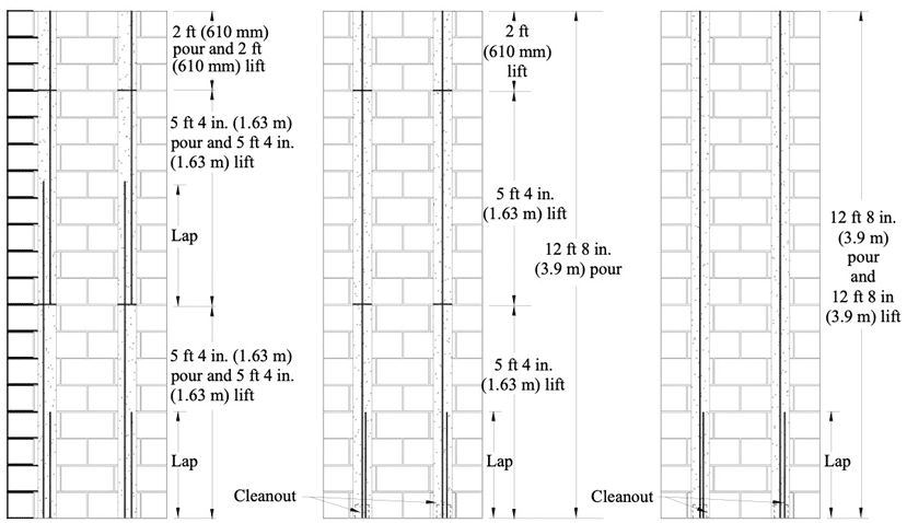
As shown in the following figure, low-lift grouting refers to the process of constructing discrete sections of masonry in heights not exceeding 5 ft-4 in. (1.63 m). Once the maximum permitted height of masonry is installed, reinforcement is placed in the intended cells followed by the grout. Continuity of the reinforcement is maintained by splicing between each section. In some areas of the country such as the Western US, low-lift grouting with continuous, unspliced, vertical reinforcement for the full story height by placing open ended units (A-block or H-block) around the reinforcement after the first lift. In high-lift grouting, the height of masonry constructed prior to grouting can be as large as 24 ft (7.63 m), subject to additional grout space limitations [1]. For both high-lift and low-lift grouting, the grout lift is limited to 5 ft-4in. (1.63 m) unless the following conditions can be met, in which case the grout lift can be increased to 12 ft-8 in. (3.86 m):

  • the constructed masonry has cured for a least 4 hours,
  • the grout slump is between 10 and 11 in. (254 and 279 mm)
  • there is no horizontal bond beam reinforcement in the lift except at the top of the lift.

Each grout lift must be consolidated and reconsolidated by mechanical vibration unless self-consolidating grout is used, in which case no consolidation is required and the grout can be placed to the full pour height as long as the constructed masonry has cured for at least four hours.

The code also permits the modification of these prescriptive grout placement procedures provided that the alternative grout placement method(s) can be shown to be adequate through a grout demonstration panel. Additional information on grouting procedures and grout demonstration panels is provided in CMHA TEK 03-02A [2].

The advantages of each method are as follows:

Low-Lift Grouting

  • Cleanouts are not required;
  • The likelihood of blow-outs is reduced;
  • Some fixity is established in reinforced masonry after 12 hours of grout curing offers reduced external bracing requirements under certain conditions.
  • Visually seeing and placing the vertical reinforcement at 5 ft-4 in. (1.63 m) intervals may improve the likelihood of reinforcement being properly located.

High-Lift Grouting:

  • Masons can continue building the wall to greater heights than 5 ft-4 in. (1.63 m) without having move to another section of the wall (greater efficiency).
  • More grout and masonry placed in one operation for better efficiency of labor and material delivery.

Grouting without cleanouts: (Low-Lift) No cleanouts required. Wall built in 3 stages. Bars spliced at pour height. Three grout lifts

Grouting with cleanouts: (High-Lift) Cleanouts required. Wall built full height. Bars installed full length (no splicing). Three grout lifts

Grouting with cleanout per MSJC: (High-Lift alternate) Cleanouts required. Wall built full height. Bars installed full length (no splicing). One grout lift

Figure 1— Comparison of Grouting Methods for a 12 ft-8 in. (3.86 m) High Concrete Masonry Wall

  • Compared to splicing at each lift low lift method
    • Significantly less reinforcement required with fewer splices.
    • Less labor in placing units over stubbed up splice from previous lift.
  • Compared to preplacement of reinforcement and using A-block and/or H-block
    • Support and bracing of reinforcement extending substantially above each pour is averted
    • Units with end webs are less likely to break during shipment and handling.
REFERENCES
  1. Specification for Masonry Structures, TMS 602-13/ACI 530.1-13/ASCE 6-13. The Masonry Society, 2013.
  2. Grouting Concrete Masonry Walls, CMHA TEK 03-02A, Concrete Masonry & Hardscapes Association.

Are There ASTM Standards for Manufactured Stone Veneer?

Revised 2016

Yes. ASTM C1670/C1670M, Standard Specification for Adhered Manufactured Stone Masonry Veneer Units, addresses the minimum requirements for manufactured stone veneer units and ASTM C1780, Standard Practice for Installation Methods for Adhered Manufactured Stone Masonry Veneer, covers requirements for the installation of adhered manufactured stone veneer systems.

ASTM C1670/C1670M covers the minimum product requirements for the units used in adhered manufactured stone masonry veneer systems. This standard covers acceptable materials, physical requirements, dimensional allowances, and finish and appearance requirements for the units. Table 1 shows a short summary of the physical requirements for manufactured stone veneer units.

Table 1—Summary of ASTM C1670/C1670M-16 Physical Requirements

Additionally, the units shall have an average thickness of no more than 2.625 inches (67 mm), with no face dimension greater than 36 inches (915 mm). The total face area of any unit shall not exceed 5 ft2 (0.5 m2).

ASTM C1780 covers standard installation practices for adhered manufactured stone masonry veneer systems. This includes requirements for materials used, acceptable job conditions, and recommended installation practices over several different substrates.

The materials section of the Practice includes units, lath, acceptable mortars, mortar admixtures and pigments, lath fasteners, weep screeds, and related flashing materials. For job conditions, the Practice provides information on how to handle hot and cold weather construction requirements. The substrates covered in the Practice include:

  • Masonry
  • Wood/Metal Framing
  • Sheathed Frame Substrate
  • Existing Cured Stucco (as a replacement for scratch coat)
  • Cast-in-Place Concrete or Precast Concrete Tilt-up Walls

For each of these substrates, surface condition, water resistive barrier installation, lath installation, scratch coat, and stone installation are covered.

Additional information on the installation of manufactured stone veneer systems is also available in the Installation Guide and Detailing Options for Compliance with ASTM C1780 for Adhered Manufactured Stone Veneer.

Both ASTM standards are available through ASTM at www. astm.org.

How Can Concrete Masonry Assemblies Comply With Code- Mandated Air Barrier Requirements?

Revised 2024

The International Energy Conservation Code [1] includes performance requirements for air barrier materials and systems. In the 2021 IECC, except for Climate Zone 2B, commercial buildings have requirements for these air barriers and systems. Compliance can be determined by whole building testing, or through use of certain materials and systems.

The requirements for materials and systems are as follows (per C402.5.1.3.1 and C402.5.1.4 of the 2021 IECC):

  • Materials shall have an air permeability not greater than 0.004 cfm/ft2 (0.02 L/s-m2) under a pressure differential of 0.3-inch water gauge (75 Pa) when tested in accordance with ASTM E2178.
  • Assemblies of materials and components shall have an average air leakage not greater than 0.04 cfm/ft2 (0.2L/s-m2) under a pressure differential of 0.3 in. of water gauge (75 Pa) when tested in accordance with ASTM  E2357, E1677, D8052 or E283.

In addition to the performance requirements listed above, there are several ‘deem-to-comply’ options for both materials and assemblies listed in the IECC. These would not require any additional testing, but rather would automatically comply with air barrier requirements. This list includes:

  • Options specific to masonry construction:
    • Fully grouted concrete masonry (although listed as a material, this compliance option is more accurately deemed an assembly),
    • As a material, Portland cement/sand parge or gypsum plaster with a minimum thickness of 5/8 in. (16 mm),
    • As an assembly, Portland cement/sand parge, stucco or plaster with a minimum thickness of 1/2 in. (13 mm), and
    • Concrete masonry walls with either one application of block filler or two coats of paint or sealer coating.
  • Other relevant options:
    • Extruded polystyrene insulation board with a minimum thickness of 1/2 in. (13 mm) with joints sealed,
    • Foil-backed polyisocyanurate insulation board with a minimum thickness of 1/2 in. (13 mm) with joints sealed,
    • Closed-cell spray foam insulation with a minimum density of 1.5 pcf (2.4 kg/m3) with a minimum thickness of 1-1/2 in. (36 mm),
    • Open-cell spray foam insulation with a density between 0.4 and 1.5 pcf (0.6 – 2.4 kg/m3) with a minimum thickness of 4-1/2 in. (114 mm), and
    • Gypsum wallboard with a minimum thickness of 1/2 in. (13 mm) with joints sealed.
    • Cement board having a thickness of not less than ½ in. (12.7 mm).
    • As a material, solid or hollow masonry constructed of clay or shale masonry units.
    • As an assembly, masonry walls constructed of clay or shale masonry units with a nominal width of 4 inches (102 mm) or more.

Any of the ‘deem-to-comply’ options can be used in order to comply with the air barrier requirements. Other methods could be used, so long as the materials or assembly are tested and comply with the performance requirements in the IECC. For materials (such as sheet or rigid board products), testing is conducted in accordance with ASTM E2178, Standard Test Method for Air Permeance of Building Materials [2]. For assemblies, there are several methods available, but one commonly used is ASTM E283, Standard Test Method for
Determining Rate of Air Leakage Through Exterior Windows,
Curtain Walls, and Doors Under Specified Pressure Differences
Across the Specimen [3]. This method could be used for concrete masonry walls with specific coatings or finishes.

For multi-wythe assemblies, there are many options for air barrier compliance. Many of the ‘deem-to-comply’ materials can be used in the cavity of the assembly; such as spray foam insulation. There are also many proprietary systems available from a variety of manufacturers that are intended for use in the cavity of multi-wythe assemblies.

Single-wythe assemblies do not have as many options, but there
are still several ways to comply. Solid grouting is a deem-to comply option. There are also proprietary and non-proprietary surface coatings that can be utilized. In addition to the deem to-comply options, NCMA performed research that shows that single coats of paint or block filler can reduce the air leakage of a concrete masonry assembly below the required limits. More information can be found in NCMA Report MR36 [4].

For more information, please see CMHA TEK 06-14A [6].

References

1. International Energy Conservation Code 2021. International Code Council, 2021.

2. Standard Test Method for Air Leakage Rate and Calculation of Air Permeance of Building Materials, ASTM E2178-21a. ASTM International, 2021.

3. Standard Test Method for Determining Rate of Air Leakage Through Exterior Windows, Curtain Walls, and Doors Under Specified Pressure Differences Across the Specimen, ASTM E283-19. ASTM International, 2019.

4. Assessment of the Effectiveness of Water Repellents and Other Surface Coatings on Reducing the Air Permeance of Single Wythe Concrete Masonry Assemblies, MR36. National Concrete Masonry Association, 2010.

5. International Energy Conservation Code 2021. International Code Council, 2021.

6. Control of Air Leakage in Concrete Masonry Walls, CHMA TEK 06-14A, Concrete Masonry & Hardscapes Association, 2011.

Is Wet-Sticking of Reinforcement a Permitted Practice?

Revised 2014

No, wet-sticking of reinforcement in masonry construction is not recognized by the current construction requirements of TMS 602/ACI 530.1/ASCE 6, Specification for Masonry Structures, which in turn defines the minimum acceptable practices for the construction of masonry adopted by model building codes.

The term wet-sticking refers to the process of placing grout within the cells or cavities of a masonry assembly followed by the placement of reinforcement. Article 3.2E of TMS 602/ACI 530.1/ASCE 6 specifically states:

3.2 E. Reinforcement – Place reinforcement and ties in grout spaces prior to grouting.

This provision has existed, essentially unchanged, since the 1990s.

Although the process of placing reinforcement subsequent to grout placement has been argued to have merit due to the reduced reinforcement congestion, which in turn allows the grout to flow more readily into the assembly, wet-sticking lends to several potential logistical and performance problems:

  1. Masonry inspection requires the verification of reinforcement spacing and location prior to grout placement, which cannot be accomplished if the grout is placed before the reinforcement;
  2. Placement tolerances for the reinforcement are difficult (if not impossible) to control when placing reinforcement into freshly placed grout; and
  3. The bond between the grout and the reinforcement can be compromised, particularly when the grout has begun to set prior to the installation of the reinforcement.

Can “Equivalent R-Value” be Used to Determine Compliance With Mass Wall Energy Code Requirements?

Revised 2014

No. The Equivalent R-Value of concrete masonry assemblies (or any mass wall system) cannot be used to determine compliance with energy code requirements. The Equivalent R-Value – also referred to as the Effective R- Value, Mass-Enhanced R-Value, Dynamic R-Value, as well as other names – is essentially a means of capturing and combining the effectiveness of thermal mass with the commonly understood steady-state R-value property of a system or material.

Despite the prevalent use of the term Equivalent R-Value, there is no single, standardized method of determining such a property for a material or assembly. Further, because some published Equivalent R-Values take into account not only conventional steady-state R-Value and thermal mass, but other intrinsic properties such as relative air leakage potential, local climate, and even building orientation, users are often left confused as to how to compare different materials or understand the context in which they were developed.

While Equivalent R-Values can help to illustrate that concrete masonry mass wall assemblies do not require the same level of insulation as non-mass wall assemblies while provided the same or better level of thermal efficiency, they cannot be used to determine compliance with energy codes. Building codes and standards only use steady- state R-Values and inherently take into account the thermal mass benefits of mass wall construction by requiring smaller steady-state R-Values for mass walls than corresponding light frame construction. Using Equivalent R- Values for demonstrating code compliance would be the same as taking credit for the same thermal property more than once.

Current building code requirements for energy efficiency stipulate minimum steady-state R-Values, which for concrete masonry construction are determined through physical testing (using procedures such as ASTM C1363 [1]) or by calculation using the code-defined series parallel (also called isothermal planes) method. While it is true that the steady-state R-Values does not factor any time-dependent heat transfer characteristics, such as heat capacity (thermal mass) of a material, or the effect of climate conditions, building orientation, or other dynamic factors that influence thermal performance, for application to the minimum energy efficiency requirements in the International Energy Conservation Code (IECC) [2] Equivalent R-Values of mass wall construction are meaningless.

It is important to note that building codes and standards use the term equivalent R-value in the context of steel frame construction. In this context the term effective R-value is accounting for the extremely high level of thermal bridging that occurs in steel stud construction. For example, a metal framed wall insulated with R-13 batt insulation between the studs may only have an effective R-Value of about R-8 when considering the assembly as a whole. While this use of effective R-value is appropriate for these steel structures, it does not have relevance to concrete masonry wall assemblies.

Resources

More details and information on thermal calculations and performance of concrete masonry construction can be found in the references:

  1. Standard Test Method for Thermal Performance of Building Materials and Envelope Assemblies by Means of a Hot Box Apparatus, ASTM C1363-11. ASTM International, 2011.
  2. International Energy Conservation Code 2021. International Code Council, 2021
  3. Thermal Catalog of Concrete Masonry Wall Assemblies, Second Edition. National Concrete Masonry Association, 2012.
  4. R-Values and U-Factors for Single Wythe Concrete Masonry Walls, CMHA TEK 06-01C, Concrete Masonry & Hardscapes Association
  5. Bradfield, Maribeth, The Effectiveness of Effective R Value, Masonry Edge/The Story Pole Magazine Vol. 6, No. 3. Masonry Advisory Council and Masonry Institute of Michigan, 2011.

Can I Wet Cut Masonry Units? And How Wet Is Too Wet?

Revised 2017

Yes. Wet cutting of concrete masonry unit (CMU) is permitted. This is explicitly permitted in the Standard Specification for Masonry Structures TMS 602 [1]. A masonry unit having 50% or more of its surface area observed to be wet is considered to have unacceptable moisture content and this is included as an industry recommended guidance in CMHA TEK 03-01C [2].

Moisture content of CMU can increase due to rain or other sources. Excessive moisture within a CMU can have various negative impacts such as shrinkage and possible cracking, compromising bond strength between mortar and CMU (for unreinforced masonry), and decrease in mason productivity. CMHA TEK 03-01C, along with the industry recommended guidance for moisture content, outlines a simple field procedure that can be done to determine the moisture content of a CMU. The procedure is used to determine if a unit has less than 50% of surface area wet, or has 50% or more of the surface area wet. The test was developed by CMHA to provide an easy marker to determine if a masonry unit is too wet to be installed. The procedure is done by wetting the surface of a “damped” CMU after which the following observations and conclusions are made:

  1. If the surface of the unit is observed to be wet but darkens when the free water is applied, then the unit is considered damp (less than 50% of the surface area is wet).
  2. Conversely, if the surface of the unit is observed to be wet but does not darken when free water is applied then unit is considered wet (50% or more of the surface area is wet).

The Occupational Safety and Health Administration (OSHA) [3] recently issued a rule to limit exposure to respirable crystalline silica, as such, wet cutting of masonry units is one of the acceptable methods prescribed by OSHA to control the release of silica into the air. The rule was made to curb the effects that prolong exposure to silica may have such as, lung cancer, silicosis, chronic obstructive pulmonary disease and kidney disease. The rule became effective on June 23, 2016 mandating different industries to meet most of the requirements by various deadlines as follows:

  • Construction – Compliance by June 23, 2017 (one year after effective date)
  • General Industry and Maritime – Compliance by June 23, 2018 (two years after effective date)
REFERENCES
  1. Specification for Masonry Structures, TMS 602-16. The Masonry Society, 2016.
  2. All-Weather Concrete Masonry Construction, TEK 03-01C, CMHA, 2002.
  3. OSHA, OSHA’s Final Rule to Protect Workers from Exposure to Respirable Crystalline Silica. United States Department of Labor, 2016. https://www.osha.gov/silica/