Resources

ACB Revetment Design— Factor of Safety Method

INTRODUCTION

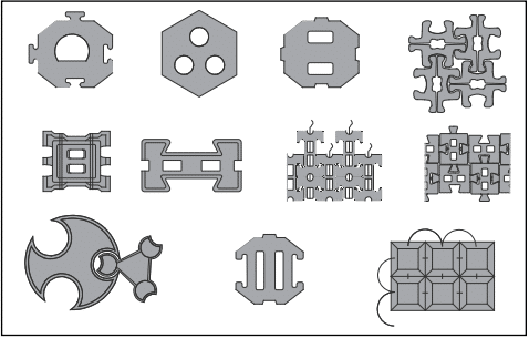
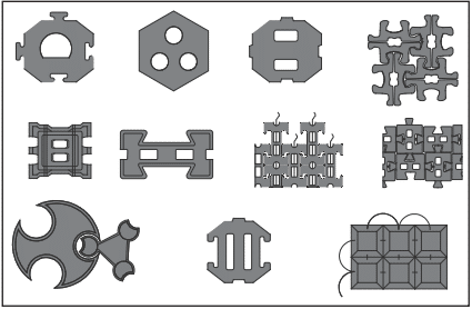
This Tech Note is intended to help designers understand the ACB design methodology and the different variables influencing the design and safety factor selection. Articulating concrete block (ACB) systems provide erosion protection to soil exposed to the hydraulic forces of moving water. ACB systems are a matrix of individual concrete blocks placed closely together to form an erosion-resistant overlay with specific hydraulic performance characteristics. Because it is composed of individual units, the ACB system can conform to minor changes in the subgrade without loss of intimate contact. Systems may be connected through geometric interlock and/or other components such as cables. Systems with openings in the blocks can typically be vegetated to provide a “green” channel and facilitate infiltration/exfiltration of channel moisture. Figure 1 illustrates a variety of ACB systems, but is not all-inclusive of available systems.

ACB units are concrete block produced in accordance with Standard Specification for Materials and Manufacture of Articulating Concrete Block (ACB) Revetment Systems, ASTM D6684 (ref. 1). Units must conform to minimum compressive strength, absorption and geometric specifications tested in accordance with Standard Test Methods for Sampling and Testing Concrete Masonry Units and Related Units, ASTM C140 (ref. 2).

This Tech Note addresses the structural stability of ACB revetment systems as a function of site-specific hydraulic conditions and unit characteristics. This Tech Note does not address geotextile filter and/or subgrade filter design, minimum installation guidelines critical to the proper performance of ACB revetments, or minimum upstream or downstream toe treatments. These topics are covered in design manuals such as references 5 and 6.
FACTOR OF SAFETY METHOD

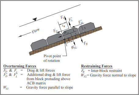
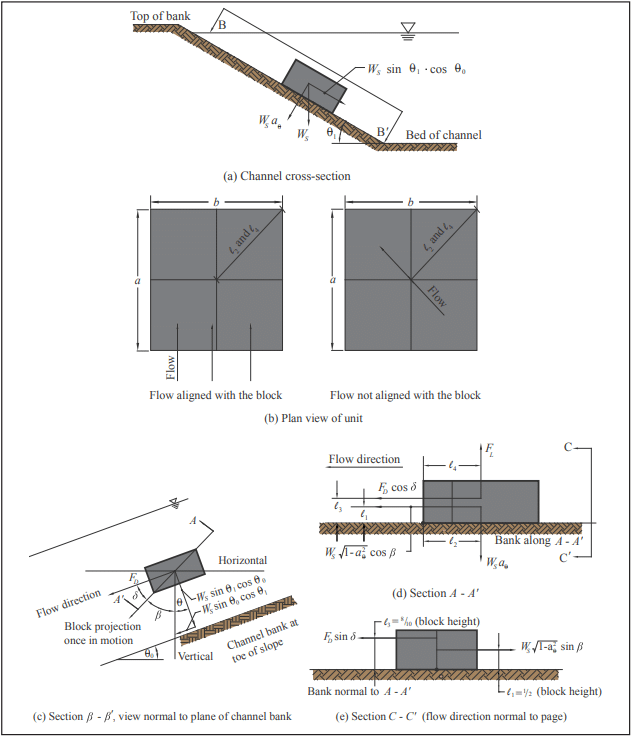
Similar to many rip rap sizing methods, the Factor of Safety method quantifies hydraulic stability of ACB systems using a “discrete particle” approach (see ref. 7). The design method involves balancing the driving and resisting forces, including gravity, drag and lift as illustrated in Figure 2. In typical channel and spillway applications, failure due to sliding (slipping) of the ACB revetment along the bed is remote. The revetment system is more apt to fail as a result of overturning about the downstream edge of the ACB unit, or downstream corner point when the ACB unit is located on the side slope of a steep channel. For cases where the revetment is placed on steep side slopes (2H:1V or steeper), the design should evaluate the potential for slip shear failures along geosynthetic-ACB unit interfaces induced by hydraulic and gravitational forces (i.e., potential slope instability).

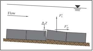
Fundamental principles of open channel flow and rigid body mechanics are used along with hydraulic test results supplied by manufacturers. The size and weight of the ACB units, as well as performance data from full-scale laboratory testing, are considered in evaluating the ratio of resisting to overturning moments (the “force balance” approach). This ratio defines the factor of safety against uplift. The design procedure accounts for additional forces applied to the unit when protrusions above the matrix occur, such as subgrade irregularities or due to improper placement (see Figure 3). Failure is defined as loss of intimate contact between the ACB unit and subgrade. The effects of cables or rods, vegetative root anchorage or mechanical anchorage devices are conservatively ignored.
Target Factor of Safety

There are several factors that need to be understood and considered when evaluating the appropriate target safety factor for design purposes. These can be categorized into two groups; external and internal factors. The external group consists of factors such as the complexity of the hydraulic system, the uncertainty of the input hydraulics, and the overall consequence of failure. These uncertainties are accounted for in the design by incorporating them into the target safety factor.

As discussed below, there are multiple facets of the safety factor methodology that are considered as they relate to external and internal design factors.

External Factors
  1. Complexity of the hydraulic system and uncertainty of the input hydraulics.
    All hydraulic systems are not of the same complexity. Modeling the flow characteristics of a stream bank or channel is much different than the design of scour protection around bridge piers. If the flow is relatively uniform and predictable, then the designer may select a lower value for the target safety factor. As the complexity of the system increases, so too should the sophistication of the model used to determine the hydraulic parameters. Utilizing a simplistic model in a complex environment may warrant an increase in the target safety factor (i.e., greater than 1.5). Conversely, if a complex model is used to analyze a simplistic design scenario, then a lower target safety factor may be adequate (i.e., less than 1.5).
  2. Consequence of failure.
    As with the complexity of the hydraulic system, the overall consequence of failure needs to be understood. Failure that results in loss of life is much different from a failure resulting in soil erosion along a stream bank in which no loss of life or property is imminent. Increasing the target safety factor is one way of potentially offsetting environmental conditions that are considered high risk.
Internal Factors
  1. Extrapolation of Test Data.
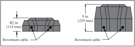
    In order to use the safety factor methodology, the critical shear stress of the unit along a horizontal surface must be understood and quantified. An equation is used for the extrapolation of test results from a steeper bed slope to a horizontal slope. A second extrapolation takes place from the tested units to thicker, untested units. In both processes, it is assumed that the intra-block restraint is the same for all thicknesses of the units. Under this assumption, the extrapolation equations only consider the weight and thickness of the units. This moment balance approach (obtained from the geometry of the unit) neglects any intra-block restraint. This assumption can be very conservative given the fact that thicker units have much more intra-block friction than thinner units given the shape of the blocks. As illustrated in Figure 4, the bottom half of an ACB unit is essentially a rectangle of concrete with adjacent units resting against six surrounding units (because the units are placed in a running bond pattern, there are six adjacent units, rather than four). As the unit increases in thickness, so too does the intra-block friction. Currently, the safety factor methodology does not account for this variable, which only increases the conservatism of this design approach for such conditions.
  2. Performance Values.
    Hydraulic testing on different “footprint” or classes of blocks and tapers for a variety of dam overtopping and spillway applications has been performed by system manufacturers. In many of these tests, the testing facility was unable to fail the system under a 4 ft (1.2 m) and 5 ft (1.5 m) overtopping scenario. Nevertheless, the resulting shear stresses obtained from the tests are used within the safety factor methodology as a threshold, or failure, shear stress. This issue is compounded when extrapolating to thicker units. Without being able to reach a threshold condition in the testing flume, licensors and manufacturers extrapolate shear stress value from a stable value. A large degree of conservatism in the performance values of the units is the result of not being able to fail these systems under laboratory conditions.
  3. Interaction between Velocity and Shear Stress.
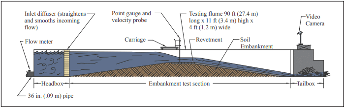
    In flume testing of the units (see Fig. 5), two of the most important results obtained are: a stable shear stress; and, velocity at a downstream point under the highest flow conditions.Consider for example testing results whereby the highest boundary shear stress and velocity obtained was 22.2 lb/ft² (1,063 Pa) and 26.1 ft/s (7.96 m/s), respectively. In the safety factor methodology one utilizes a shear stress of 22.2 lb/ft² (1,063 Pa) regardless of the expected design velocity for every design utilizing this particular unit (provided that the design velocity is less than or equal to the tested velocity). Common “hydraulic” sense would state that if the velocity was only 12 ft/s (3.66 m/s) for a given application, then the system could withstand a much larger shear stress than 22.2 lb/ft² (1,063 Pa). Therefore, an additional degree of conservatism is present when the design velocity is less than the tested velocity and the design utilizes the maximum shear stress generated during the higher velocity event.
  4. Allowable shear stress in a vegetated state.
    All of the testing on existing ACB systems has taken place in a non-vegetated state. In contrast, many ACB applications for overtopping and spillway applications seek a final system that is fully vegetated. A series of hydraulic tests conducted by the U.S. Army Corp of Engineers investigated the performance of identical ACB systems in both vegetated and non-vegetated conditions (ref. 14). The end result was an increase in the allowable shear stress of 41% when vegetated.

Taking into consideration all of the points addressed above, what is the proper target safety factor required for a dam overtopping or spillway application? It is safe to state that the methodology used for ACB design is full of conservative assumptions. From the fact that tapered ACB systems have not reached their threshold condition in the testing flume to the fact that vegetation increases the allowable shear stress, it is apparent that the resulting safety factor can be conservative by 20 – 50%. Therefore, a target safety factor of 1.3 – 1.5 is adequate for applications in which the design hydraulics and site geometry are clearly understood, such as dam overtopping or spillway applications. Ultimately, the “external” factors and overall design of the project will need to be evaluated and decided on by the engineer of record. It may also be appropriate for an individual experienced in ACB design to offer an opinion on how these factors should be incorporated into an overall target safety factor.
Hydraulic Considerations

The main hydraulic variable in ACB stability design is the total hydraulic load (or bed shear stress) created by a varying discharge within a fixed geometric cross-section. The ratio of designed average cross-sectional bed shear to the ACB’s critical shear value (obtained from testing) is used, in part, for practical analysis and evaluation of ACB stability. The cross-section averaged bed shear stress, τo, can be calculated for design using a simple equation (ref. 13):

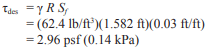
τo = γ R Sf

τo is applied over the channel boundary, regardless of o channel lining. Shear stress is a function of the hydraulic radius and the slope of the energy line (for the simplest case—the bed slope), both defined by channel geometry and flow conditions.

The cross-section averaged bed shear stress is suitable for uniform flow conditions such as those found in long straight reaches of open channels with uniform cross section. It may be determined using simplified model approaches, such as the Manning equation or the HEC-RAS model (ref. 11). For cases involving bends, confluences, constrictions and flow obstructions, more sophisticated hydraulic modeling is generally appropriate, such as a two-dimensional model which can evaluate time-dependent flow conditions or complex geometry (ref. 10).

Design velocity is often determined using the Manning Equation for steady uniform flow as follows (ref. 13):

An iterative process is used to determine the flow depth, yo, because both the area and hydraulic radius are functions of yo. Cross-sectional averaged velocity of flow is then defined as V = Q/A. As noted previously, complex hydraulic systems require sophisticated modeling to determine averaged velocity.

The cross-sectional averaged bed shear stress and cross sectional averaged velocity should be determined by a design professional familiar with hydraulic design practices.

ACB Revetment Considerations

Historically, manufacturers of ACB systems published performance data from full-scale tests performed in accordance with Federal Highway Administration guidelines (ref. 8). Two relatively new ASTM standards have been developed based on the FHWA method: Standard Guide for Analysis and Interpretation of Test Data for Articulating Concrete Block (ACB) Revetment Systems in Open Channel Flow, ASTM D7276 (ref. 3) and Standard Test Method for Performance Testing of Articulating Concrete Block (ACB) Revetment Systems for Hydraulic Stability in Open Channel Flow, ASTM D7277 (ref. 4), that eventually will replace the FHWA test method. This data provides the critical shear stress, τc, and is based on specific flow conditions and ACB system characteristics. The manufacturer should specify whether the critical shear stress is for a unit on a horizontal surface or on an inclined surface. Values for a unit on a horizontal surface are commonly specified. It is important that the designer consider the full-scale test configuration and hydraulic conditions used to derive the critical shear stress on a horizontal surface.

Testing involves the construction of a full-scale test embankment that is subsequently exposed to hydraulic load until failure—defined as the local loss of intimate contact between the ACB unit and the subgrade it protects. A schematic of a typical flume is illustrated in Figure 5. ACB system stability is evaluated by summing the driving and resisting moments about the toe of an individual ACB unit. The inter-block restraint, FR, is ignored, as is any contribution from cables, anchorages and vegetation (see Figure 2).

ACB placement or subgrade irregularities can result in one unit protruding above the ACB matrix, as shown in Figure 3. The protrusion height, ΔZ, is a function of installation practice and block-to-block interface, and is often assumed to be ¼ to ½ in. (6 to 13 mm). However, the designer must consider site-specific conditions and adjust ΔZ as required. The lift force, F’L, resulting from the protrusion is conservatively assumed equal to the drag force, F’D.

The established design methodology assumed that the flow was parallel to the block and calculated the drag forces using the block width perpendicular to the flow, b (see equation for F’D in Table 1 and Figure 6b). However, in the field not all ACB applications have the flow aligned with the sides of the block. To account for that uncertainty, it is recommended that the diagonal distance of the block, 2l2, be used instead of b in the drag force calculations (see Figure 6b). It is recommended that the designer analyze the project conditions and determine the appropriate dimension for determining the drag forces, F’D, and safety factors on each project. Examples of non-parallel flow conditions are open channels and levees where the flow alignment is uncertain during the life of the project.

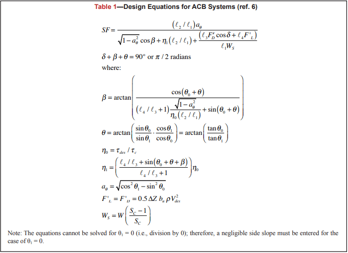
The factor of safety against loss of intimate contact is considered to be a function of design bed shear stress, critical shear stress, channel geometry and ACB unit geometry and weight. Figure 2 illustrates unit moment arms based on unit geometry. The safety factor for a single ACB unit is determined from the ratio of restraining moments to overturning moments. Considering the submerged unit weight, WS, unit moment arms and drag and lift forces, the safety factor, SF is defined as (ref. 6):

Dividing by l1WS and substituting terms, the equation for SF resolves to that presented in Table 1. Table 1 also outlines the calculations necessary for determining factor of safety.
DESIGN EXAMPLE

A trapezoidal channel section with 3H:1V side slopes (Z = 3, θ1 = 18.4°) and a base width b of 15 ft (4.6 m) requires stabilization. The 100-year design discharge is 450 ft³/s (12.7 m³/s), and the channel slope So is 0.03 ft/ft (0.03 m/m) (θ0 = 1.72°). The channel has a uniform bed and no flow obstructions (i.e. confluences, bends or changes in geometry). Manning’s n is specified as 0.035. Based on design conditions, the energy grade line Sf is assumed equal to the channel slope So.

Step 1 Determine flow depth and cross-sectional averaged velocity:
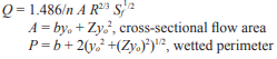
R = A/P, hydraulic radius

By iteration, the flow depth yo is determined to be 2.1 ft (0.6 m).

Step 2 Calculate design shear stress:
Step 3 Select target factor of safety:
Based on the analysis of the project conditions, such as type of application, low consequence of failure and the empirical hydraulic model, the designer has recommended a target factor of safety, SFT, for the project of 2.34.

Step 4 Select potential ACB product and obtain geomorphic and critical shear stress data:
The proposed ACB manufacturer specifies a critical shear stress, τc, for the unit on a horizontal surface of 30 psf (1.4 kPa) for a maximum velocity of 20 ft/s (6.1 m/s), submerged unit weight of 38 lb (17.2 kg) and dimensions of 15 (w) x 18 (l) x 5 (h) in. (381 x 457 x 127 mm).

Step 5 Calculate factor of safety against incipient unit movement:
Given;
Ws = 35 lb (16 kg)
bu = 1.5 ft (460 mm)
τc = 30 psf (1.4 kPa)
ηo = 2.96/30 = 0.0987

and determining the following geometrically (see Figure 6);
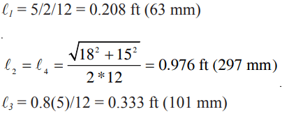
and assuming (see discussion);
ΔZ = 0.0417 ft (13 mm)

the following are calculated using the equations in Table 1:

For this open channel application the flow is not considered to align with the block, so b = 2l2
aθ = 0.948
θ = 5.16°
β = 19.4°
η1 = 0.08
δ = 65.4°
SF = 2.43

Because the calculated factor of safety exceeds the target, the proposed ACB system is stable against loss of intimate contact.

An ACB Design Spreadsheet (ref. 15) that makes these calculations much easier is available free on request via the CMHA  web site.

NOTATIONS:

A = cross-sectional flow area, ft² (m²)
aq = projection of Ws into subgrade beneath block (Table 1)
b = width of channel base, ft (mm)
bu = width of ACB unit in the direction of flow, ft (mm)
FD = drag force, lb (kN)
F’D = additional drag forces, lb (kN)
FL = lift force, lb (kN)
F’L = additional lift forces, lb (kN) (Table 1)
FR = inter-block restraint, lb (kN)
lx = block moment arms, ft (mm)
n = Manning’s roughness coefficient
Q = design discharge, ft³/s (m³/s)
R = hydraulic radius (A/wetted perimeter), ft (m)
SC = specific gravity of concrete (assume 2.1)
Sf = energy grade line, ft/ft (m/m)
So = bed slope, ft/ft (m/m)
SF = calculated factor of safety (Table 1)
SFT = target factor of safety
V = cross-sectional averaged flow velocity, ft/s (m/s)
W = weight of block, lb (kg)
Ws = submerged weight of block, lb (kg) (Table 1)
Ws1 = gravity force parallel to slope, lb (kN)
Ws2 = gravity force normal to slope, lb (kN)
yo = flow depth, ft (m)
Z = horizontal to vertical ratio of channel side slope
β = angle of block projection from downward direction, once in motion, degrees or radians
γ = unit weight of water, 62.4 pcf (1,000 kg/m³)
ΔZ = height of block protrusion above ACB matrix, ft (mm)
δ = angle between drag force and block motion, degrees or radians
ηo = stability number for a horizontal surface (Table 1)
η1 = stability number for a sloped surface (Table 1)
θ = angle between side slope projection of WS and the vertical, degrees or radians (Table 1)
θ0 = channel bed slope, degrees or radians
θ1 = channel side slope, degrees or radians
ρ = mass density of water, 1.94 slugs/ft³ (1,000 kg/m³)
τc = critical shear stress for block on a horizontal surface, lb/ft² (kPa)
τdes = design shear stress, lb/ft² (kPa)
τo = cross-section averaged bed shear stress, lb/ft² (kPa)

REFERENCES

  1. Standard Specification for Materials and Manufacture of Articulating Concrete Block (ACB) Revetment Systems, ASTM D6684-04(2010). ASTM International, 2010.
  2. Standard Test Methods for Sampling and Testing Concrete Masonry Units and Related Units, ASTM C140-09. ASTM International, 2010.
  3. Standard Guide for Analysis and Interpretation of Test Data for Articulating Concrete Block (ACB) Revetment Systems in Open Channel Flow, ASTM D7276-08. ASTM International, 2010.
  4. Standard Test Method for Performance Testing of Articulating Concrete Block (ACB) Revetment Systems for Hydraulic Stability in Open Channel Flow, ASTM D7277-08. ASTM International, 2010
  5. Design Manual for Articulating Concrete Block Systems. Harris County Flood Control District, Houston, Texas, 2001.
  6. Design Manual for Articulating Concrete Block, ACBMAN-001-20. Concrete Masonry & Hardscapes Association, 2020.
  7. Bridge Scour and Stream Instability Countermeasures: Experience, Selection, and Design Guidance – 3rd Edition. Federal Highway Administration Hydraulic Engineering Circular No. 23.
  8. Clopper, P. E. and Y. Chen. Minimizing Embankment Damage During Overtopping Flow, Technical Report FHWA RD-88-181. Federal Highway Administration, 1988.
  9. Clopper, P. E. Hydraulic Stability of Articulated Concrete Block Revetment Systems During Overtopping Flow, Technical Report FHWA RD-89-199. Federal Highway Administration, 1989.
  10. RMA2 Version 4.5. United States Army Corps of Engineers. USACE Waterways Experiment Station, 2008.
  11. HEC-RAS Version 4.1. United States Army Corps of Engineers. USACE Hydrologic Engineering Center, 2010.
  12. Articulated Concrete Block for Erosion Control, ACBTEC-001-14, Concrete Masonry & Hardscapes Association, Herndon, Virginia, 2014.
  13. Morris, H. M. and J. Wiggert. Applied Hydraulics in Engineering, Second Edition, James Wiley & Sons, 1972.
  14. Lipscomb, C.M, C.I. Thornton, S.R. Abt, and J. R. Leech. Performance of Articulated Concrete Blocks in Vegetated and Un-Vegetated Conditions. Proceedings of the International Erosion Control Association 32nd Annual Conference and Exposition, Las Vegas, NV, February 5-8, 2001.
  15. Articulating Concrete Block (ACB) Design Spreadsheet, ACB-XLS-001-19. Concrete Masonry & Hardscapes Association, Herndon, Virginia, 2019.

Articulating Concrete Block for Erosion Control

INTRODUCTION

An articulating concrete block (ACB) system is a matrix of individual concrete blocks placed together to form an erosion-resistant overlay with specific hydraulic performance characteristics. The system includes a filter layer underlay that allows infiltration and exfiltration to occur while providing particle retention of the soil subgrade. The filter layer may be comprised of a geotextile or properly graded aggregate or both. The blocks within the matrix must be dense and durable while providing a matrix that is flexible and porous.

Articulating concrete block systems are used to provide protection to underlying soil materials. The term “articulating” implies the ability of individual blocks of the system to conform to changes in subgrade while remaining interlocked or otherwise restrained by virtue of the block geometric interlock and/or additional system components such as cables, ropes, geotextiles, or geogrids. The interlocking property provided by the special shapes of ACBs also allows for expansion and contraction. Long-term durability and sustainability relies on an appropriate engineered design based on site-specific hydrological and geotechnical conditions. They are either hand-placed or installed as pre-assembled mats on top of a filter layer on prepared subgrade, and act as a soil revetment.

Articulating concrete blocks (ACBs) are an effective erosion control system used to solve a wide variety of erosion problems:

  • drainage channels
  • wildlife habitat
  • river fronts
  • bridge abutments/piers
  • coastal shorelines
  • dikes and levees
  • pipeline protection
  • spillways
  • boat ramps
  • retention basins
  • lake shorelines
  • overflow channels
  • low water crossings
  • dam overtopping

The systems are easy to install, simple to produce, and environmentally friendly. ACB systems are often used as an alternative to cast-in-place concrete bulkheads and slope paving, gabions, soil cement, roller compacted concrete, or rock riprap. ACBs can also be used as grid pavers. However, grid pavers manufactured according to ASTM C1319, Standard Specification for Concrete Grid Paving Units (ref. 7), are not considered ACBs.

Articulating concrete blocks are produced in accordance with ASTM D6684, Standard Specification for Materials and Manufacture of Articulating Concrete Block (ACB) Revetment Systems (ref. 3). They can be made in a variety of shapes and thicknesses, and may even be colored according to preference. ACBs have excellent resistance to hydraulic shear and overtopping conditions. Design resources for ACBs include the Design Manual for Articulating Concrete Block and ACB Design Spreadsheet (refs. 2, 8).

ENVIRONMENTAL BENEFITS

One of the environmental benefits of ACB erosion systems is that vertical cores and spaces can be incorporated throughout the system, which allows vegetation growth. Properly selected plant species can almost completely cover the entire hard surface of the ACBs, allowing them to blend in with the natural look of the project as well as water purification by absorbing nutrients and breaking down other pollutants. During peak storm events, the ACB layer beneath the vegetation will protect the soil from erosion. The ability to support the ecosystem’s habitat is a major advantage of ACB systems over other erosion control methods. Additional advantages of ACB systems are:

  • serviceability
  • aesthetics
  • pedestrian safety
  • sustainability
  • cost effectiveness
  • flexibility

The permeability of ACBs allows their use to preserve natural drainage and treatment systems. ACBs installed on filter media are pervious surfaces that reduce water runoff and flooding risks, improve water quality, reduce pollutants, recharge aquifers and prevent erosion. These environmental characteristics permit the use of ACBs on sustainable developments to preserve or improve existing sites and can be applicable to credits in some green building rating systems, such as LEEDTM, which is discussed in more detail below.

ACBs installed over drainage layers can also be used in a Best Management Practices (BMP) plan to preserve or improve existing sites, or in new developments. The system installed over a drainage layer preserves the natural drainage and treatment systems of the soil, reducing water runoff and flooding risks, improving water quality, reducing pollutants, recharging aquifers, and preventing erosion. Research on permeable pavers that are installed in a similar manner to ACBs (block over a gravel drainage layer) has also shown a promotion of aerobic biodegradation of hydrocarbons and reduction of nutrients (refs. 11, 12). When vegetated, they can also generate habitat. These qualities make ACBs a great solution for use in sustainable projects where water quantity and quality control are extremely important.

LEED Certification

ACBs can also make a significant contribution to project certification under Leader in Energy and Environmental Design (LEED) registered projects. Under LEED v3 for New Construction (ref. 9), ACB products can help attain points toward certification in the following categories: Sustainable Sites, Materials & Resources, and potentially Innovation in Design and Regional Priority Credits. These are briefly discussed below, based on LEED v3 for New Construction. Other versions of LEED may have different credit numbers, or slightly different criteria. For more detailed information on ACB’s potential contributions towards LEED credits, see TEK 06-09C, Concrete Masonry and Hardscape Products in LEED 2009 (ref. 10).

Sustainable Sites: ACBs can help capture up to 5 credits of the 26 possible in the following areas:

  • Prerequisite—The project is required to reduce the pollution generated during construction. ACBs can contribute to preventing erosion, reducing dust when working as drivable surfaces, and constructing sediment basins with the added support for vegetation growth that increases water quality.
  • Credit 5.1, Protect or Restore Habitat—ACBs can be used to restore erosion-prone areas by retaining soil and promoting plant growth.
  • Credit 5.2, Maximize Open Spaces—Ponds constructed with ACBs may count as open space as long as they are vegetated and meet the maximum 1:4 (vertical : horizontal) side slope limit.
  • Credit 6.1, Storm Design: Quantity Control—Using ACBs can reduce a site’s impermeable hardscaping for slope stability and erosion control, allowing stormwater to percolate into the ground and reducing runoff. In addition, receiving channels protected with ACBs can reduce erosion, reduce impervious surfaces and, when planted, contribute to the overall aesthetics and ecology.
  • Credit 6.2, Storm Design: Quality Control—ACBs can also be used to reduce the amount of stormwater that requires treatment. As discussed above under Environmental Benefits, ACBs on gravel filters have been shown to improve runoff quality.
  • Credit 7.1, Heat Island Effect: Non Roof—Open grid ACBs (at least 50% pervious) or with a Solar Reflectance Index (SRI) of at least 29 can be used in lieu of traditional concrete or asphalt to reduce the urban heat island effect.

Materials and Resources: ACBs can contribute towards 8 of the 14 possible credits in the following areas:

  • Credit 2, Construction Waste Management— Damaged concrete products can be redirected to the manufacturing process for recycling and unused products can be reused on another project.
  • Credit 3, Material Reuse—ACBs can potentially be salvaged from one project and reused in another.
  • Credit 4, Recycled Content—Concrete products, including ACBs, can be manufactured using recycled materials that have been diverted from the waste stream.
  • Credit 5, Regional Materials—Concrete hardscape products are usually available close to the point-of-use and are manufactured with local materials.

Innovation in Design: Projects can earn Innovation in Design credits by exceeding the LEED credit requirements, or by addressing innovative environmental strategies not specifically addressed in LEED, such as the life cycle environmental impact of the materials used.

Regional Priority Credits: Up to 4 LEED credits can be earned through Regional Priority Credits, which are designed to encourage designers to focus on specific regional needs. The credits are classified by zip code and designers have the option to excel in aspects of the project that are priorities in their region. ACBs could contribute to attain higher percentages on all the credits mentioned above to qualify for extra points.

ACB UNITS

ACB units complying with ASTM D6684, Standard Specification for Materials and Manufacture of Articulating Concrete Block (ACB) Revetment Systems (ref. 3), are produced as dry-cast (in a block machine) or wet-cast (with concrete and molds). Sampling and testing of dry-cast ACB units are performed in accordance with ASTM C140, Standard Test Method for Sampling and Testing Concrete Masonry Units and Related Units (ref. 6), for conformance with the requirements in Table 1. Sampling and testing of wet-cast units is performed in accordance with ASTM C39, Standard Test Method for Compressive Strength of Cylindrical Concrete Specimens and ASTM C42, Standard Test Method for Obtaining and Testing Drilled Cores and Sawed Beams of Concrete (refs. 4, 5).

Several varieties of ACB systems are available: interlocking, cable-tied and non-cable-tied matrices, and open cell and closed cell varieties. Open cell units contain open voids within individual units that facilitate the placement of aggregate and/or vegetated soil. Closed cell units are solid concrete elements that are capable of allowing vegetation growth between adjacent units. Figure 1 shows a variety of ACB units in plan view.

ACB INSTALLATION

Articulating concrete blocks can be installed by small construction crews with a modest amount of equipment. Installations are fast and are easy to inspect due to the visibility of all components.

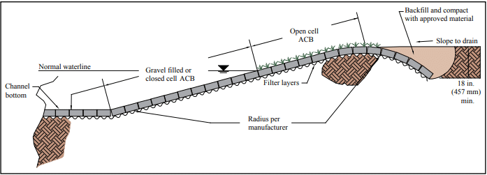
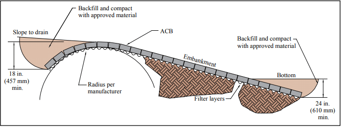
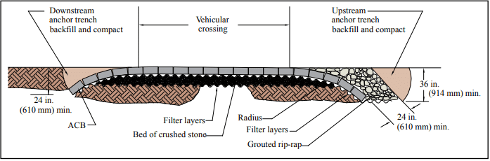
ACBs are installed on top of a filter layer over a prepared subgrade. The filter acts to protect and hold the subgrade in place while allowing bidirectional water penetration. Final subgrade elevation should be 0 to + ½ in. (12.7 mm) under a 10 ft. (3.05 m) straight edge. After the ACB installation is complete, the open cell voids or joints between the ACB units are filled with granular material or soil. Unit to unit vertical offset should be limited to the value utilized in the design. If vegetation is required, hydraulic seeding or mulching provides a low cost and highly effective method of establishing commonly used grasses and plants. In applications subject to continually flowing water, solid units should be used below the normal waterline or the voids of hollow units should be filled with gravel. Figures 2 through 4 show typical ACB cross-sections.

Installation methods depend on whether the ACB product being used is classified as cabled or as non-cabled.

Cabled Articulating Concrete Mats

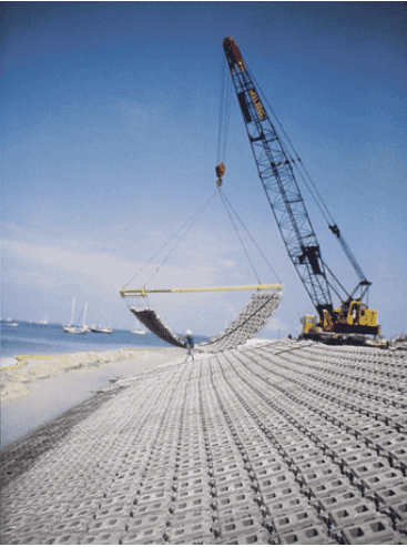
Cabled interlocking blocks have preformed horizontal holes cast in them so that high-strength cables or ropes (synthetic or steel) can be installed through the matrix of blocks binding them into a monolithic mattress. The cables or ropes are used to facilitate placement of the mat, normally by a spreader bar and crane, as shown in Figures 5 and 6. For design purposes, cables offer no hydraulic stability or structural value to the ACB mat or block system.

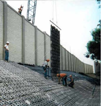
The blocks are pre-assembled into cabled mats in a controlled environment on or off the job site. The mats are lifted by the cables’ end loops, placed on the back of a flatbed truck, and shipped to the job site where they are again lifted and placed on the prepared slope. The mats can also be fabricated on site near the prescribed area, eliminating the need for additional trucking. Assembly of the blocks into mats makes it possible to install these systems underwater and on steep slopes.

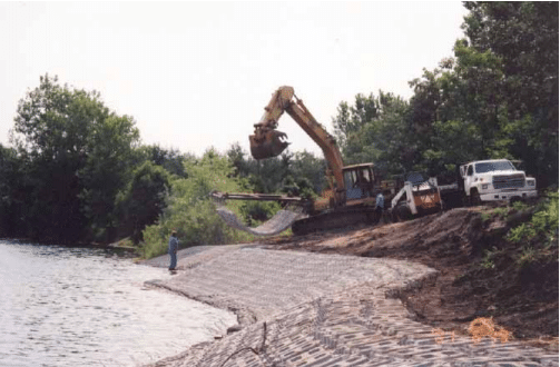
Several commercially available cable systems can be manually placed on a shoreline or channel, and the cables then hand-inserted through the holes. An advantage of this process is that revetments with fewer seams can be constructed. Also, it is easier to hand-place the blocks around a radius or projection on a sloped bank, such as a culvert outlet. To accomplish this with pre-assembled ACB mats, custom-shaped mats must be fabricated or field piece work insertions are required. Both require careful planning, detailing, and execution in the field.

Non-Cabled Articulating Concrete Mats

Non-cabled blocks are cast in interlocking shapes to provide a positively connected matrix that is individually hand-placed by semi-skilled labor. The blocks are individually installed according to the geometry of the product. The typical block layout is oriented in the application’s centerline position. These blocks make it possible to install ACBs in areas that are restrictive to large construction equipment.

ACBs without cables can be suited to projects where complex site geometries and limited access are present. These non-cabled ACBs offer comparable shear resistance and some systems offer a higher percentage of open surface area when desired. These blocks are typically delivered in palletized cubes and are hand-placed at the job site. Since there are no cables involved, the material costs can be considerably less. ACBs without cables can be constructed in virtually seamless fields.

DESIGN CONSIDERATIONS

Existing and proposed project characteristics combined with the hydraulic design objectives will determine, through a factor of safety analysis, the ACB product that will best serve the project’s erosion control needs. A 1.5 factor of safety is common.

Guidelines for the selection and design of the appropriate ACB product are provided by the Design Manual for Articulating Concrete Block (ref. 2) and TEK 11-12A, Articulating Concrete Block Revetment Design—Factor of Safety Method (ref. 1).

The hydraulic forces which are considered in the design of erosion control projects using this technology are hydraulic lift, drag, and impact. ACBs have demonstrated the ability to resist high velocity flows in excess of 25 ft/s (7.6 m/s), usually associated with drainage channels, water control structures, dam spillways, and fast flowing rivers. While many of the forces created by water can be readily calculated, particularly uplift and drag, each project application has separate design considerations.

ACBs are not designed to add structural strength to the slopes. The protected slope must be geotechnically stable prior to placement of surface protection. Known as “flexible revetments,” ACB installations should not be placed on slopes which are steeper than the natural angle of repose of the soil. This is a different technology than retaining walls which resist lateral earth pressures.

Protruding height variances between adjacent blocks should be minimized and must be in accordance with the design value utilized. Grading beneath the block and fabric is critical to establishing an acceptable finished profile of the ACBs.

Filter layers are always placed under the ACBs. The function of the filter is critical, as it must retain the soil in place while letting water pass through without clogging. The filter layer must remain in intimate contact with the block and the soil to preclude soil particles from being transported down the slope beneath the geotextile. The key design points to consider in the filter selection are:

  • Only woven monofilament or nonwoven needle-punched geotextiles should be considered for filter applications.
  • The filter layer must have a long-term permeability capable of handling the required volume of water through a restricted surface area equal to the joint area of the articulating concrete block.
  • The permeability of the filter layer must always be equal to or greater than the permeability of the protected soil unless a special bedding layer is provided.
  • The filter layer needs only to retain the majority of particles beneath it, thus creating a filter bridge.

Care should be taken in the specification of the underlying geotextile filter layer. Appropriate ASTM test methods are available to characterize soil properties and should be done to develop the retention criteria and proper permeability. The geotextile must possess adequate strength and endurance properties to survive the process of installation and any long-term forces applied to it. ASTM D6684, Standard Specification for Materials and Manufacture of Articulating Concrete Block (ACB) Revetment Systems (ref. 3), provides strength requirements for geotextiles.

In most of these designs, the owner or architect should rely upon the engineering expertise of a qualified engineer to select the appropriate block type, filter layer, soil compaction, and design parameters. Proper material selection and construction practices are required and should be checked during installation.

REFERENCES

  1. Articulating Concrete Block Revetment Design—Factor of Safety Method, ACB-TEC-002-11, Concrete Masonry & Hardscapes Association, 2002
  2. Design Manual for Articulating Concrete Block, ACB- MAN-001-20, Concrete Masonry & Hardscapes Association, 2020.
  3. Standard Specification for Materials and Manufacture of Articulating Concrete Block (ACB) Revetment Systems, ASTM D6684. ASTM International, 2018.
  4. Standard Test Method for Compressive Strength of Cylindrical Concrete Specimens, ASTM C39/C39M. ASTM International, 2021.
  5. Standard Test Method for Obtaining and Testing Drilled Cores and Sawed Beams of Concrete, ASTM C42/42M. ASTM International, 2020.
  6. Standard Test Method for Sampling and Testing Concrete Masonry Units and Related Units, ASTM C140. ASTM International, 2023A.
  7. Standard Specification for Concrete Grid Paving Units, ASTM C1319. ASTM International, 2021.
  8. ACB Design Spreadsheet
  9. Leadership in Energy and Environmental Design (LEED) Green Building Rating System, v3. United States Green Building Council, 2009.
  10. Concrete Masonry and Hardscape Products in LEED 2009, TEK 06-09C, Concrete Masonry & Hardscapes Association, 2009.
  11. Hunt, W.F., Collins, K.A., Hathaway, J.M. Hydrologic and Water Quality Evaluation of Four Permeable Pavements in North Carolina, USA. Proceedings of the 9th International Conference on Concrete Block Paving. Buenos Aires, Argentina, 2009.
  12. Kirkpatrick, R., Campbell, R, Smyth, J., Murtagh, J., Knapton, J. Improvement Of Water Quality By Coarse Graded Aggregates In Permeable Pavements. Proceedings of the 9th International Conference on Concrete Block Paving. Buenos Aires, Argentina, 2009.


Grout for Concrete Masonry

INTRODUCTION

Masonry grout is a cementitious mixture used to fill cores or cavities in masonry construction. While usually added for structural reasons, grout can also increase: fire ratings, security, acoustical performance, termite resistance, blast resistance, thermal storage capacity and anchorage capabilities. Grout is composed of cement, aggregate, lime (optional) and sufficient water to allow ease of placement and ensure complete filling of the grout space. With approval, admixtures may be added to the grout mix. The high initial water content of typical grout mixes compensates for water absorption by the masonry during and after grout placement. The final water-to-cement ratio is significantly reduced, thus grout develops high compressive strength despite its apparent high initial water to cement ratio.

Generally, grout is used to structurally bond wall elements into a wall system. The most common example is in reinforced construction, where grout bonds the steel reinforcing bars to the masonry, allowing them to act as one system in resisting loads. Composite walls consist of two wythes of masonry with a solidly grouted collar joint with or without reinforcing steel. Grouted cores also increase the net cross sectional area of concrete masonry and permit walls to carry higher compressive, shear loads and lateral loads. Masonry cantilever retaining walls are often solidly grouted to increase the wall’s weight, and hence resistance to overturning. Grouted masonry construction is not required to be reinforced, but typically is for design economy. Reinforced masonry construction, however, requires grout to be placed around the reinforcement.

This TEK includes information about: types of grout; grout properties; grout admixtures; and self consolidating grout. Information on grout mixing and placement and on grout testing is contained in Grouting Concrete Masonry Walls, TEK 03-02A and Grout Quality Assurance, TEK 18-08B (refs. 1, 2) respectively.

SPECIFYING GROUT

Grout Type

Grout for use in concrete masonry construction should comply with ASTM C 476, Standard Specification for Grout for Masonry (ref. 3), or the governing building code which may permit grouting options other than those in set forth in ASTM C 476 . ASTM C 476 defines two types of grout: fine and coarse. Fine grout contains sand smaller than 3/8 in. (9.5 mm) as its only aggregate, while coarse grout allows pea gravel smaller than 1/2 in. (13 mm), or other acceptable aggregate, in addition to the sand.

Aggregates for grout must comply with ASTM C 404, Standard Specification for Aggregates for Masonry Grout (ref. 4), which includes requirements for grading, impurities, soundness, and methods of aggregate sampling and testing. When an aggregate does not meet the ASTM C 404 grading requirements, it may still be used provided the requirements of ASTM C 404 section 4.2 are met. These requirements prescribe minimum and maximum aggregate sizes and a minimum grout compressive strength of 2,000 psi (13.79 MPa).

Building codes and ASTM Specifications do not recognize any appreciable compressive strength difference between fine and coarse grouts. The choice of grout type therefore depends primarily on the minimum clear dimensions of the grout space, the grout pour height and construction economics. Coarse grout is typically more economical to produce. See TEK 03-02A (ref. 1) for more information on grout space requirements and grout type selection.

Grout Proportions

ASTM C 476 allows grout mixtures to be determined either by compliance with the proportions listed in Table 1 or by those established through compressive strength testing. Written acceptance of grout mix submittals is required prior to the commencement of grouting operations (ref. 7).

Using the proportions specified in Table 1 is a simple way to demonstrate compliance with ASTM C 476.

When using the specified compressive strength method in ASTM C 476, the grout must be sampled and tested in accordance with ASTM C 1019 (ref. 5) and have a minimum compressive strength of 2,000 psi (13.79 MPa) at 28 days. It must also be mixed to a slump of 8 to 11 in. (203 279 mm) as determined by ASTM C 143/143M (ref. 6). The grout proportions used to produce a grout with acceptable physical properties are then used to produce the grout for the project.

Compressive Strength

While 2,000 psi (13.79 MPa) is the minimum compressive strength required by ASTM C 476, project requirements may require higher strengths. For instance, when the unit strength method is used to determine the specified compressive strength of the masonry, f’m, Specification for Masonry Structures (ref. 7) requires the compressive strength of the grout to equal or exceed f’m but not be less than 2,000 psi (13.79 MPa). As an economic rule of thumb, unless structural criteria dictate otherwise, it is best to balance the specified grout strength with the specified concrete masonry assembly strength so that one element of the system is not considerably stronger than the other, resulting in material overstrength and design conservatism. When using the strength design provisions of the Building Code Requirements for Masonry Structures (ref. 8), a maximum specified grout compressive strength of 5,000 psi (34.47 MPa) for concrete masonry construction is applied. This limitation is based solely on the specified compressive strength of grout and does not limit the actual field-tested grout compressive strength.

Grout Slump

Grout for masonry construction is a high slump material with a flowable consistency to ease placement and facilitate consolidation. Both the Specification for Masonry Structures (ref. 7) and ASTM C476 require grout to have a slump between 8 and 11 in. (203 – 279 mm). Grout must be fluid enough to flow into the smallest grout spaces and around any obstructions, such as reinforcing bars, joint reinforcement, anchors, ties and small mortar protrusions (fins). Lower slump grouts are usually more difficult to place. Although the high slump (high initial water cement ratio of conventional grout) may concern those familiar with lower slump cementitious products such as concrete or mortar, concrete masonry units are absorptive, and the higher water content of grout is critical to insure that in-place grout has sufficient remaining water, after absorption by the masonry units, for cement hydration. Despite grout’s relatively high water to cement ratio, studies have shown that adequate grout compressive strengths and bond strengths are achieved even when using high slump grouts in wet concrete masonry units (ref. 9).

While both codes and standards specify grout slumps in excess of 8 in. (203 mm), there may be certain conditions where lower slumps could be used or may be warranted. For example, if the concrete masonry units are low absorptive units or if the grout spaces are large and the grout lifts are short, lower water content grouts may work fine although care should be taken to assure adequate filling around reinforcement or other obstructions. Likewise, cold weather could present conditions where lower water content grout would be advantageous under certain circumstances (i.e. freezing conditions), but not as a general rule. For demonstrating the suitability of alternate grouting means and/or methods, the grout demonstration panel option detailed in Specification for Masonry Structures (ref. 7) should be used to qualify the proposed method. See CMHA TEK 03-02A (ref. 1) for information on grout demonstration panels.

Production Methods

Production methods for grout are also described in ASTM C 476. These include various forms of site-mixed and ready mixed grout. When cementitious materials and aggregates are stored separately on site and then proportioned into the mixer, they are required to be mixed for at least 5 minutes in a mechanical mixer with sufficient water to bring the grout to the desired consistency. Factory dry blended cementitious materials and aggregate can also be delivered to the job site and must be mixed for the same 5 minute time period. Another option is for the individual dry ingredients to be shipped to the job site in compartments and then mixed with water on site using continuous proportioning equipment and auger mixing to the desired consistency. Grout also may arrive at the job site in a wet-mixed condition. Ready-mixed grout may have the slump adjusted at the site to bring it to the desired consistency. If water is added, the grout must be remixed for at least 1 minute before discharging. When approved by the specifier, grout may be mixed by hand instead of a mechanical mixer when only small volumes are required.

Grout quantities required on a job can vary depending on the specific circumstances of the project. The unit properties, such as absorption and configuration, can have a significant impact.

The delivery method (pumping versus bucketing) can also introduce different amounts of waste. Although the absolute volume of grout waste seen on a large project may be larger than on a comparable small project, smaller projects may experience a larger percentage of grout waste. Table 2 provides guidance for estimating grout quantities.

ADMIXTURES

A variety of admixtures is available to enhance certain grout properties. However, ASTM C 476 requires admixtures to be included in the project documents or to be approved by the purchaser. Likewise, Specification for Masonry Structures (ref. 7) requires admixtures to be accepted by the architect or engineer. Antifreeze compounds, used to lower the freezing point of grout, are prohibited by ASTM C 476. Admixtures containing chlorides should also not be used in grout, because chlorides may corrode steel reinforcement and can contribute to efflorescence in the wall. Several admixtures are available that provide a combination of desirable characteristics, such as shrinkage compensating, plasticizing and retarding. As with any admixture, manufacturer’s directions and dosage rates should be carefully followed. Note that individual admixture results can vary from one cement supplier to another.

Superplasticizers

Superplasticizing admixtures are used to reduce the water content of a plastic cementitious mix while maintaining high flow consistency. They are not normally used in conventional grout (except self consolidating grout) since the excess water is absorbed into the masonry units. In some areas, however, this absorption of excess water has resulted in efflorescence problems. Superplasticizers have been found effective in reducing this problem by reducing the amount of water available for absorption. It should be noted however, that special formulation skills are required to ensure that the grout remains fluid long enough to completely fill all the voids.

Accelerators

In grout, accelerating admixtures increase both the rate of hydration and the amount of heat generated during hydration. They are used in cold weather to decrease grout setting time and increase the rate of strength gain. The increased heat of hydration does not eliminate the need for cold weather protection requirements. Accelerators should be free of chloride materials and not perpetuate the corrosion of embedded metals.

Shrinkage Compensators

Shrinkage compensating admixtures cause a slow, controlled grout expansion that is intended to offset grout shrinkage due to the initial water loss. These admixtures may be especially useful for high-lift grouting, where a large volume of grout is placed and consolidated at one time.

Retarders

Retarding admixtures are used in hot weather to keep the grout workable long enough for placement, consolidation and reconsolidation. They may also be used when the grout cannot be placed right away, as may be the case when the plastic grout will travel a long distance to the job site.

Fly Ash and Blast-Furnace Slag

Fly ash is a by-product of coal combustion, and is not usually thought of as an admixture in the same sense as the chemical admixtures discussed above. Fly ash can be used in grout as a pumping aid or to provide a greater slump with less water. Fly ash can also replace some of the portland cement in the grout mix, which has an economic advantage since the unit cost of fly ash is less than that of portland cement.

Addition rates of fly ash and raw natural pozzolans (ref. 10) or blast furnace slag (ref. 11) are governed by ASTM C 595, Standard Specification for Blended Hydraulic Cements (ref. 12). These products can produce grout mixes with a slower initial strength gain, which may need to be considered in cold weather to achieve the minimum compressive strength previously discussed.

SELF-CONSOLIDATING GROUT

A new grout material is becoming increasingly known in North American masonry markets – self-consolidating grout (SCG). SCG is a highly fluid and stable grout mix that is easy to place and does not require consolidation or reconsolidation. SCG’s mix design is significantly different from conventional grout. SCG is similar in nature to conventional grout, with the exception that the proportions of constituent materials are highly controlled and admixtures (typically in the form of superplasticizers with or without viscosity modifiers) are used to produce a plastic grout with desired properties. Controlled aggregate gradation is also important to maintain fluidity without segregation, to produce a mix that results in consistent properties throughout the grout lift.

Because of the fluid nature of the material, traditional measures of consistency and flow such as the slump cone test (ASTM C 143) are not applicable to SCG. A slump flow test is used instead, which is an adaptation of the conventional slump cone test. In the slump flow test, SCG is loaded into an inverted slump cone. The cone is removed and the flow of the material is observed and measured. Typical slump flow spreads for SCG range from 20 to 30 in. (508-762 mm). Indications of bleeding or segregation should not be seen in the flow spread.

SCG is a relatively new material so it is not yet incorporated into building codes and standards. To date, compliance has been achieved in several cases by using the grout demonstration panel option in Specification for Masonry Structures (ref. 7). Work is under way to standardize and codify this material.

REFERENCES

  1. Grouting Concrete Masonry Walls, TEK 03-02A, Concrete Masonry & Hardscapes Association, 2005.
  2. Grout Quality Assurance, TEK 18-08B, Concrete Masonry & Hardscapes Association, 2005.
  3. Standard Specification for Grout for Masonry, ASTM C 476-02. ASTM International, 2002.
  4. Standard Specification for Aggregates for Masonry Grout, ASTM C 404-04. ASTM International, 2004.
  5. Standard Test Method for Sampling and Testing Grout, ASTM C 1019-03. ASTM International, 2003.
  6. Standard Test Method for Slump of Hydraulic-Cement Concrete, ASTM C 143/143M-03. ASTM International, 2003.
  7. Specification for Masonry Structures, ACI 530.1-05/ASCE 6-05/TMS 602-05. Reported by the Masonry Standards Joint Committee, 2005.
  8. Building Code Requirements for Masonry Structures, ACI 530-05/ASCE 5-05/TMS 402-05. Reported by the Masonry Standards Joint Committee, 2005.
  9. The Effects of Concrete Masonry Unit Moisture Content on Grout Bond and Grout Compressive Strength, MR 11. Concrete Masonry & Hardscapes Association Research and Development Laboratory, 1997.
  10. Standard Specification for Coal Fly Ash and Raw or Calcined Natural Pozzolan for Use in Concrete, ASTM C 618-03. ASTM International, 2003.
  11. Standard Specification for Ground Granulated Blast Furnace Slag for Use in Concrete and Mortars, ASTM C 989-05. ASTM International, 2005.
  12. Standard Specification for Blended Hydraulic Cements, ASTM C 595–03. ASTM International, 2003.

Plaster and Stucco for Concrete Masonry

INTRODUCTION

Portland cement-based plaster has many useful applications: as a moisture resistant coating for concrete masonry walls; as an interior wall finish in residential and commercial structures; and as an exterior architectural treatment for buildings of all types.

The terms cement plaster and cement stucco are used interchangeably. They both describe a combination of cement and aggregate mixed with a suitable amount of water to form a plastic mixture that will adhere to a surface and preserve the texture imposed on it.

When freshly mixed, plaster is a pliable, easily workable material. It can be applied either by hand or machine in two or three coats, although two-coat applications are more typical when plaster is applied to newly constructed concrete masonry.

While plaster may be used as an interior or exterior finish for most building materials, some type of metal reinforcement or mechanical keying system is usually required to effectively attach the plaster to the substrate. Concrete masonry, however, provides an excellent base for plaster without the need for reinforcement. Since block is manufactured of the same cementitious material as that in the plaster, the two have a natural affinity.

MATERIALS

Of primary importance to the performance of the finished surface is the selection and use of proper materials. Each must be evaluated on its ability to provide serviceability, durability, and satisfactory appearance. Standard Specification for Application of Portland Cement-Based Plaster, ASTM C 926 (ref. 3) includes specifications for materials for use in plaster

Cement

Cement should comply to one of the following product specifications:

  • Blended hydraulic cement —ASTM C 595 (ref. 4)
    Types IP, IP(M), IS, IS(M), and their air-entrained
    counterparts IP-A, IP(M)-A, IS-A, IS(M)-A
  • Masonry cement—ASTM C 91 (ref. 5) Types M, S, N
  • Portland cement—ASTM C 150 (ref. 6)
    Types I, II, III, and their air-entrained counterparts IA, IIA,
    IIIA
  • Plastic cement—UBC 25-1 (ref. 1)
  • White portland cement—ASTM C 150 (ref. 6) Types I, IA,
    III, IIIA

Aggregates

Aggregates used in plaster should conform to the chemical and physical requirements of ASTM C 897, Standard Specification for Aggregate For Job-Mixed Portland Cement Plasters (ref. 2), except as noted below. Recommendations for gradation of the sand to be used in the base coat are listed in Table 1.

Aggregates used for finish coats need not comply with the gradation requirements of ASTM C 897. Various sizes and shapes can be evaluated with test panels to obtain special textures or finishes. As a starting point, all aggregates for finish-coat plaster should be below a No. 16 sieve and uniformly graded. Uniform gradation produces plaster that is easier to apply. If necessary, larger aggregate may be added to obtain the desired appearance.

MIXTURES

Properly proportioned mixtures can be recognized by their workability, ease of application, adhesiveness to the base, and resistance to sagging.

The combinations of cementitious materials and aggregates shown in Table 2 have proven to provide satisfactory performance. These proportions are recommended for first and second coat applications.

Considerations in selecting the plaster mix include suction of the masonry, its surface irregularities, climate extremes, extent of surface exposure, and method of application. For economy and simplicity, it is better to select the same plaster type for both scratch (first) and brown coat (second coat in a three coat application) applications, adjusting the proportions for the brown coat to allow for a larger aggregate to cement ratio.

The finish coat can be varied in appearance by changing the size and shape of the aggregate, by adding color, by changing the consistency of the finish mix, and by the application method. For the finish coat, a factory prepared mixture may be used or the finish coat may be proportioned and mixed at the jobsite. Job-mixed finish coat plaster will provide a truer color and more pleasing appearance if white portland cement is used in conjunction with a fine-graded, light colored sand. Recommendations for job mixed finish coat proportions are listed in Table 3.

The success of plastering depends on proper batching and mixing of the individual and combined materials. Water is placed in the mixer first, after which half of the sand is added. Next the cement and any admixtures are added. Finally, the balance of the sand is added and mixing is continued until the batch is uniform and of the proper consistency, which usually takes 3 or 4 minutes.

Although batching by shovelfuls remains the most commonly used method in the field, shovelful batching should be checked daily by volume measures to establish both the required number of shovelfuls of each ingredient and the volume of mortar in the mixer when a batch is properly proportioned. Water additions should also be batched using containers of known volume. Proper mixing should result in a uniform blend of all materials.

PLASTER APPLICATION

Open textured concrete masonry units, laid with flush (nontooled) joints, should be specified on walls intended to be plastered. The open texture promotes a good mechanical bond between the plaster and the masonry. New concrete masonry walls should be properly aligned and free from any surface contamination, such as mortar droppings or sand. It is important that the wall be properly cured and carrying almost all of its design dead load before the plaster is applied. Existing masonry walls should be inspected for alignment, and any coatings or surface treatments other than portland cement paint be should removed by sandblasting prior to plastering.

Plaster may be applied by hand or machine in two or three coats in accordance with the thicknesses given in Table 4. Two-coat application is most often used when plaster is applied directly to concrete masonry, and for horizontal (overhead) plaster application.

The scratch coat can be applied either from the bottom to the top of the work area, or from top to bottom. The plaster must be applied with sufficient force to fully adhere it to the masonry. Excessive troweling or movement of the scratch coat must be avoided, because too much action will break the bond between the plaster and masonry. The applied plaster must be brought to the required thickness and the surface made plumb. The thickness is established by the use of screeds and grounds. A rod or straightedge is used to even the surface when the area between the screeds and grounds is filled with plaster. The rod can bear on the screeds or contact the grounds and be moved over the surface, cutting off high spots and showing up the hollow spaces, which must be filled and rodded again.

Scratch-coat plasters are scored or scratched to promote mechanical bond when the brown coat is applied. The scratch coat should be scored in a horizontal direction; shallow scratching is adequate.

Brown-coat plasters are applied, rodded, and floated to even the surface, provide a uniform suction throughout the basecoat plaster, and provide a desirable surface for the finish coat.

The brown coat is applied in sufficient thickness to bring the surface to the proper plane. A few minutes after the plaster has been applied, the surface is rodded to the desired plane. The plaster thickness is properly gaged with plaster screeds or wood slats of proper thickness as the guides. After rodding, the surface is floated to give it the correct surface texture.

Floating of the brown coat is the most important part of plastering. Floating must be done only after the plaster has lost sufficient moisture so that the surface sheen has disappeared but before the plaster has become so rigid that it cannot be moved under the float. This interval is critical, since the degree of consolidation that occurs during floating influences the shrinkage-cracking characteristics of the plaster.

The full thickness of the base coats should be applied as rapidly as the two coats can be put in place. The second coat should be applied as soon as the first coat is sufficiently rigid to resist the pressures of second-coat application without cracking. Under certain conditions this may mean applying both first and second coats in a single day. The short delay, or even no delay, between the first and second coats promotes more intimate contact between them and more complete curing of the base coat. No stoppage of plaster should occur within a panel. The finish coat is applied to a predamped, but still absorptive, base coat to a thickness of about 1/8 in. (3.2 mm). The finish coat is applied from the top down and the whole wall surface must be covered without joinings (laps or interruptions). Table 4 summarizes the recommended nominal plaster coat thicknesses for both two and three coat work.

Differential suction between the masonry units and mortar joints may cause joint patterns to be visible in two coat applications if the first coat is too thin. This may also occur if the walls are plastered while the units contain excessive moisture.

CONTROL JOINTS

Cracks can develop in plaster from a number of causes: drying shrinkage stresses; building movement; foundation settlement; intersecting walls, ceilings, and pilasters; weakened sections in a wall from a reduction in service area or cross section because of fenestration; severe thermal changes; and construction joints.

To prevent such cracking, install control joints in the plaster coat directly over and aligned with any control joints in the base. Normally, cracking will not occur in plaster applied to uncracked masonry bases if the plaster bonds tightly to the base structure. If excessive cracking does occur, the application (particularly floating) procedure may not have provided adequate bond of plaster to concrete masonry. Altering application procedures or mechanically anchoring the plaster to the concrete masonry surface with mesh may be required.

CURING

To obtain the best results from the cementitious materials in cement plaster, moisture must be kept in the plaster for the first few days after application. The base coat should be moist cured until the finish coat is applied. Generally, fogging the surface with water at the start and again at the end of the work day will suffice. If it is hot, dry, and windy, the plaster surface should be moistened and covered with a single sheet of polyethylene plastic, weighted or taped down to prevent water loss through evaporation.

Immediately before finish-coat application, the base coat should be moistened. This moisture absorbed by the base coat and the ambient relative humidity provides total curing of the finish coat plaster (particularly colored finish coats) so that it is not necessary to further moist-cure the finish coat.

MAINTENANCE OF PLASTER

Minimal care will keep plaster attractive for many years.
Washing will keep the surface clean and the color bright.
Washing plaster wall surfaces consists of three steps:

  1. Prewet the wall, saturating it. Start at the bottom and work to the top.
  2. Use a garden hose to direct a high-pressure stream of water against the wall to loosen the dirt. Start at the top and wash the dirt down the wall to the bottom.
  3. Flush remaining dirt off the wall with a follow-up stream.

Prewetting overcomes absorption and prevents dirty wash water from being absorbed and dulling the finish. A jet nozzle on a garden hose will usually clean effectively. Do not hold the nozzle too close to the surface because the high pressure stream of water may erode the surface.

Chipped corners and small spalls can be patched with premixed mortar. The patch area should be wetted before applying plaster. Prepare premixed mortar by adding water and mixing to a doughy consistency, then trowel into the patch area, and finish to match the texture of the surrounding surface.

A fresh, new look can be given to any exterior plaster wall by applying a surface treatment of paint, portland cement paint, or other coating. Portland cement paints are mixed with clean water to a brushable consistency and laid on heavily enough to fill and seal small cracks and holes. The surface should be dampened immediately before application.

REFERENCES

  1. Plastic Cement, Uniform Building Code Standard 25-1, International Conference of Building Officials (ICBO), 1994.
  2. Standard Specification for Aggregate for Job-Mixed Portland Cement-Based Plasters, ASTM C 897-00. American Society for Testing and Materials, 2000.
  3. Standard Specification for Application of Portland Cement Based Plaster, ASTM C 926-98a. American Society for Testing and Materials, 1998.
  4. Standard Specification for Blended Hydraulic Cements, ASTM C 595-02. American Society for Testing and Materials, 2002.
  5. Standard Specification for Masonry Cement, ASTM C 91-
  6. American Society for Testing and Materials, 2001.
  7. Standard Specification for Portland Cement, ASTM C 150-
  8. American Society for Testing and Materials, 2000.

Self-Consolidating Grout for Concrete Masonry

INTRODUCTION

Self-consolidating grout (SCG) is a specially-formulated grout for use with reinforced masonry. It is designed to fill the long, narrow and sometimes highly congested cores of reinforced walls without the need for consolidation and reconsolidation by mechanical vibration or by puddling.

Self-consolidating grout has been used in various parts of the United States, under the grout demonstration panel provisions of Specification for Masonry Structures (refs. 1, 2), which is included by reference in the International Building Code (refs. 3, 4). The 2008 edition of Specification for Masonry Structures (ref. 5), however, includes explicit provisions for SCG.

Unlike conventional grout and conventional concrete, self consolidating grout (SCG) is a special application of self consolidating concrete (SCC) that uses aggregates complying with ASTM C 404, Standard Specification for Aggregates for Masonry Grout (ref. 6), as specified in ASTM C 476, Standard Specification for Grout for Masonry (ref. 7).

Similar to conventional grout, there are two types of selfconsolidating grout, coarse and fine, with the latter containing only fine aggregate. Coarse self-consolidating grout has been the most common, although fine SCG is predominant in several specific regions of the U.S.

MATERIALS FOR SELF-CONSOLIDATING GROUT

Self-consolidating grout attains a high flow not from adding more water, but from a careful mix design to create a flowable yet highly cohesive grout that will not segregate and can pass freely through congested reinforcement and narrow openings without “blocking or bridging.” SCG must maintain its fluidity without segregation and maintain consistent properties throughout the grout lift. It is composed of aggregates, cementitious materials, water and special admixtures which provide the fluidity and stability to meet performance requirements.

Aggregate Size and Proportion

To obtain the desired filling and placing ability, aggregates used in SCG should meet the requirements of ASTM C 404, as specified in ASTM C 476. The requirements for coarse aggregate, for use in coarse SCG, are essentially the same as the requirements for No. 8 and No. 89 coarse aggregate in ASTM C 33, Standard Specification for Concrete Aggregates (ref. 8): they should be either a Size No. 8 or Size No. 89 gravel, stone or air-cooled iron blast furnace slag with 100% passing the ½ in. (13 mm) sieve and at least 85 to 90% passing the 3/8 in. (9.5 mm) sieve. Fine aggregate, for use in either coarse or fine SCG, is typically Size No. 1, which is a concrete sand as defined in ASTM C 33, but could also be Size No. 2, which is a sand for masonry mortar as defined in ASTM C 144, Specification for Aggregate for Masonry Mortar (ref. 9).

ASTM C 476 contains a proportion specification as well as a performance specification for masonry grout. The proportion specification specifies that coarse grout should have fine aggregate in the amount of 2 1/4 to 3 times the sum of the volume of the cementitious materials and coarse aggregate in the amount of 1 to 2 times the sum of the volume of the cementitious materials. These ASTM C 476 requirements are equivalent to s/a (sand/total aggregate) ratios of approximately 0.50 to 0.60 on an absolute volume basis. By comparison, most self-consolidating concrete mix designs have similar s/a ratios in the 0.50 to 0.60 range.

Cementitious Materials and Minus 100 (0.150 mm) Sieve Content and Composition

Grout is required to have a minimum compressive strength of 2,000 psi (14 MPa) after 28 days of curing (ref. 7). Building Code Requirements for Masonry Structures (ref. 10) sets an upper limit on the specified compressive strength of grout at 5,000 psi (34.5 MPa) at 28 days when using strength design of concrete masonry, although experience indicates that many conventional grouts develop strengths greater than this specification limit. Note that actual strengths are somewhat higher than the specified strength to assure compliance.

In the historical context of masonry materials, the term cementitious materials has commonly referred to the cement content (as well as lime in the case of masonry mortars) used in the manufacturing of masonry units, mortar or grout. In the production of SCG, however, the fraction of very fine aggregate particles present in the mix can have a significant influence on the plastic (and by association, the hardened) properties of SCG, and therefore needs to be considered in the batching of SCG. As such, the ‘powder’ content of an SCG mix, which includes both conventional cementitious materials as well as the very fine aggregate dust smaller than the 100 (0.150 mm) sieve, is monitored to ensure a stable SCG.

Adequate paste content is critical for making stable SCG mixes because the paste forms the matrix in which the particles are suspended. This paste is composed of cementitious materials (including the powder), water and entrained air, if any. The entire powder content of some mixes may contain auxiliary materials including pozzolanic and hydraulic materials, as well as ground limestone and inert fillers. These additions can improve and maintain cohesion and segregation resistance of the mix while lowering the overall cost and helping to control the ultimate strength of the mix.

Although not widely used in the U.S., ground limestone and inert fillers can be very effective in SCG mixes as a means of keeping compressive strengths to the lower range. They should be considered if they are regionally available. Fly ash can also be an effective addition because its use can help enhance the filling ability and slump flow of the mix while providing increased cohesion and reduced sensitivity to changes in water content.

Research has shown that slump flow values are increased when the fly ash replacement rates are between 20 and 40% of portland cement (ref. 11). If the goal is to control compressive strengths, Class F fly ash can be effective because it typically does not contribute as much to strength gain as Type C fly ash. GGBFS (Ground Granulated Blast Furnace Slag) has successfully been used in SCG mixes to replace some of the cement, but its high ultimate strength gain usually means that the compressive strengths of these mixes are usually similar (or sometimes higher) than straight cement mix designs. Research (ref. 12) has demonstrated that coarse SCG mixes could be made with total cementitious materials contents of 750 lb/yd3 (445 kg/m3), and possibly with 700 lb/yd3 (415 kg/m3). By comparison, a typical conventional coarse grout made to the proportion specifications of ASTM C 476 contains about 550 to 700 lb/yd3 (325 to 415 kg/m3) of cementitious materials.

Some limited testing in the CMHA research (ref. 12) demonstrated that fine SCG could be made with total cementitious materials contents in the range of 800 to 850 lb/yd3 (475 to 505 kg/m3). By comparison, a typical conventional fine grout made to the proportion specifications of ASTM C 476 will contain about 700 to 1,000 lb/yd3 (415 to 590 kg/m3) of cementitious materials.

Water Content

The term ‘natural slump’ describes the slump of the grout mix before the polycarboxylate is added. A common procedure for making self consolidating concrete is to set the initial water target to the amount needed to bring the mix to a ‘natural slump’ of 2 to 4 in. (51 to 102 mm). The polycarboxylate is then added to make the mix fluid enough to obtain the desired slump flow. This would also be an acceptable initial water target for making SCG, although CMHA research (ref. 12) indicated that some of the most successful batches of coarse and fine SCG made with the local materials used in the research had initial water targets that yielded a ‘natural slump’ of 6 to 9 in. (152 to 229 mm) before the polycarboxylate was added.

Admixtures

Admixtures are integral to the production of SCG. The primary admixture used to impart fluidity and stability to the SCG mix is a class of high-range water-reducing admixtures known as polycarboxylates (PC). These long-chain polymers are synthesized to help keep the cement grains dispersed while adding some cohesiveness and stability to the SCG mix.

Another class of admixtures often used to make SCG in conjunction with the PC is the Viscosity-Modifying Admixtures (VMA). VMAs help adjust viscosity and can improve the cohesiveness and stability of the mix while allowing it to flow without segregation. Not all PC and VMA products have the same properties. Some PCs impart substantial amounts of stability and cohesiveness to the mix and are recommended to be used without VMA, while others benefit from the addition of VMA.

In the past (before polycarboxylates), there have been indications that in some situations superplasticizers in grout for masonry structures have not performed well because they exhibited a short pot life, meaning the mix quickly lost fluidity and rapid stiffing would follow. Absorption of mix water into the surrounding masonry also negatively impacted the flow. In high-lift grouting (placing grout into grout columns as high as 24 ft (7.3 m)), enough water could be lost to cause the grout to stiffen and bridge before reaching the bottom of the grout column. With the advent of newer high-range water reducers such as polycarboxylates, however, this problem is no longer evident (ref. 13).

Note that proportioning of SCG is not permitted in the field (ref. 5). However, final adjustment of the mix, in accordance with the SCG manufacturer’s recommendations, utilizing water or the same admixture used in the mix is permitted.

SCG PLACEMENT

Self-consolidating grout is pumped or placed into spaces to be grouted using the same procedures as for conventional grout. Research has shown that with SCG there is no need to first remove mortar fins and protrusions exceeding 1/2 in. (13 mm), as is required for conventionally grouted masonry (refs. 3, 4), since SCG is fluid enough to flow around these small obstructions (ref. 13). However, it is important to note that Specification for Masonry Structures currently requires the removal of mortar fins and protrusions exceeding 1/2 in. (13 mm) for both conventional grout and SCG (ref. 5). Note that because SCG is so fluid, it will flow through gaps wider than about 3/8 in.

(10 mm). To contain the grout, therefore, it is recommended to mortar the masonry unit cross webs of cells containing grout in partially grouted construction.

In bond beams, SCG will be adequately contained using conventional grout-stop materials, such as plastic mesh. When filling intermediate bond beams using high-lift grouting, place the grout-stop material in the bed joints both above and below the bond beam to prevent the SCG from rising above the bond beam location.

Once the SCG is placed, consolidation and reconsolidation is not necessary with either coarse or fine SCG.

Documented successful lifts of 12 ft 8 in. (3.9 m) have been achieved by filling the grout columns of 8-in. (203-mm) concrete masonry walls in a single lift in less than a minute using a concrete pump (ref. 13). Other undocumented placements have placed SCG in a single 24-ft (7.3-m) lift. Twenty-four feet (7.3 mm) is the maximum pour height currently permitted by Building Code Requirements for Masonry Structures and Specification for Masonry Structures (refs. 10, 5). Note also that for SCG, grout lift height can equal the grout pour height.

Blowouts have not been shown to be a problem for conventional masonry units in this research nor in field experience. However, specialty units with reduced or removed webs, such as “H-block” or large pilaster or column units, may require reduced lift heights.

No special curing procedures are required when using SCG. When appropriate, standard hot and cold weather construction provisions should be followed, as for other masonry projects. See All-Weather Concrete Masonry Construction, TEK 03-01C (ref. 14), for more detailed information.

SCG QUALITY ASSURANCE AND QUALITY CONTROL

Specification for Masonry Structures (ref. 5) requires SCG to:

  • meet the material requirements of ASTM C 476,
  • attain the specified compressive strength or 2,000 psi (13.79 MPa), whichever is greater, at 28 days when tested in accordance with ASTM C 1019 (ref. 15),
  • have a slump flow of 24 to 30 in. (610 to 762 mm) as determined by ASTM C 1611 (ref. 16), and
  • have a Visual Stability Index (VSI) less than or equal to 1 as determined in accordance with ASTM C 1611, Appendix X.1.

The ASTM C 476 material requirements are described in Grout for Concrete Masonry, TEK 09-04A (ref. 17). Other quality assurance and quality control provisions related to SCG are described below.

Some methods commonly used for self-consolidating concrete to evaluate passing ability, like the L-Box or J-Ring, are not normally used with SCG because experience indicates that the 3/8 in. (9.5 mm) maximum aggregate size used in SCG has adequate passing ability in masonry grouting applications.

Compressive Strength Testing of SCG Mixes

The current edition of ASTM C 1019, Standard Test Method for Sampling and Testing Grout (ref. 15), addresses the testing of SCG. The procedure for testing SCG is very similar to that for conventional grout, except that SCG is placed in the mold in one lift instead of two and SCG does not need to be rodded.

Slump Flow

The slump flow test method defined in ASTM C 1611/C 1611M, Standard Test Method for Slump Flow of Self-Consolidating Concrete (ref. 16) is used to monitor the consistency of fresh, unhardened SCG and its unconfined flow potential. It is particularly useful to assess the batch-to-batch consistency of SCG supplied over time.

Because of the fluid nature of SCG, traditional measures of consistency, such as the ASTM C 143 (ref. 18) slump test, are not applicable to SCG. The slump flow test is an adaptation of the ASTM C 143 slump cone test. In the slump flow test, SCG is loaded into an inverted slump cone in a single lift without consolidation. The cone is removed and the diameter of the grout slump flow is measured (see Figure 1).

Visual Stability Index (VSI)

VSI, also defined in ASTM C 1611, is performed after the slump flow test to provide a qualitative assessment of the SCG’s stability. The SCG patty resulting from the slump flow test is examined for aggregate segregation, bleeding and evidence of a mortar halo (a cement paste or mortar ring that has clearly separated from the coarse aggregate, around the outside circumference of the SCG patty). The SCG mix is then assigned a VSI, from 0 (highly stable) to 3 (highly unstable).

Although not required by Specification for Masonry Structures, T20 (T50) records the time it takes, during the slump flow test, for the outer edge of the SCG patty to reach a diameter of 20 in. (508 mm) from the time the mold is first raised. It is an optional test for self consolidating concrete, and is similarly applicable to SCG to provide a relative measure of the unconfined flow rate and an indication of the relative viscosity of the SCG. While the actual target value for T20 (T50) can vary for different SCG mixes, it has value in verifying the consistency between SCG batches delivered to the job site.

Self-Healing Ability ‘S’ Test

The ‘S’ test can also be used to help determine the stability of an SCG mix. While this is not a standardized test method, it is adapted from a simple test that is done by some practitioners in the field. There is a common version and a modified version, which gives an indication of the relative segregation resistance of the SCG when subjected to local vibration.

The common self-healing (non-disturbed) test is performed after the slump flow, T20 (T50) and VSI have been recorded. A 10- to 12-in. (254- to 305-mm) ‘S’ is drawn in the SCG patty with a finger, making sure to scrape off the SCG all the way down to the board. The patty is observed to see if the ‘S’ will self-heal. In cases where the self healing is excellent, the SCG flows back together and there is little or no evidence of the ‘S’ remaining. In cases where the self-healing is poor, the SCG does not flow back together and the ‘S’ remains very visible with severe aggregate, paste or water segregation.

Due to observations during the CMHA research (ref. 12), a self healing (after agitate) test was created. After completing the common self-healing test, the SCG patty is vibrated and a second test, designated self-healing (after agitate), is performed. To vibrate the mix, the side of the slump flow baseplate is lightly kicked or tapped six times with a foot (three on one side followed by three on an orthogonal [right-angle] side). The ‘S’ test is then repeated and the mix is rated again.

Suitability of Segregation Tests

In the CMHA research (ref. 12); several mixes were used to determine the suitability of self-consolidating concrete segregation tests on the SCG mixes. Testing was performed to evaluate both the Column Technique for Static Segregation (ASTM C 1610) (ref. 19) and the European Sieve Segregation Test (ref. 20). It was found that these tests were not able to distinguish unstable SCG mixes from stable mixes. It is not clear if this was a function of the particular raw materials used or a general characteristic of coarse SCG mixes. The selfhealing (after agitation) test described above was found to be a much better indicator of stable and unstable mixes for SCG.

REFERENCES

  1. Specification for Masonry Structures, ACI 530.1-02/ASCE
    6-02/TMS 602-02. Reported by the Masonry Standards
    Joint Committee, 2002.
  2. Specification for Masonry Structures, ACI 530.1-05/ASCE
    6-05/TMS 602-05. Reported by the Masonry Standards
    Joint Committee, 2005.
  3. International Building Code 2003. International Code
    Council, 2003.
  4. International Building Code 2006. International Code
    Council, 2006.
  5. Specification for Masonry Structures, ACI 530.1-08/ASCE
    6-08/TMS 602-08. Reported by the Masonry Standards
    Joint Committee, 2008.
  6. Standard Specification for Aggregates for Masonry Grout,
    ASTM C 404-07. ASTM International, Inc., 2007.
  7. Standard Specification for Grout for Masonry, ASTM C
    476-07. ASTM International, Inc., 2007.
  8. Standard Specification for Concrete Aggregates, ASTM C
    33-03. ASTM International, Inc., 2003.
  9. Standard Specification for Aggregate for Masonry Mortar,
    ASTM C 144-04. ASTM International, Inc., 2004.
  10. Building Code Requirements for Masonry Structures, ACI
    530-08/ASCE 5-08/TMS 402-08. Reported by the Masonry
    Standards Joint Committee, 2008.
  11. Studies of Self-Compacting High Performance Concrete
    with High Volume Mineral Additives. Fang, W.;Jianxiong,
    C.; Changhui, Y., Proceedings of the First International
    RILEM Symposium on Self-Compacting Concrete, 1999,
    p. 569-578.
  12. Self-Consolidating Grout Investigation: Making and
    Testing Prototype SCG Mix Designs – Report of Phase
    II Research, MR31. Concrete Masonry & Hardscapes
    Association, 2006.
  13. Self-Consolidating Grout Investigation: Compressive
    Strength, Shear Bond, Consolidation and Flow – Report
    of Phase I Research, MR29. Concrete Masonry &
    Hardscapes Association, 2006.
  14. All-Weather Concrete Masonry Construction, TEK 03-01C,
    Concrete Masonry & Hardscapes Association, 2002.
  15. Standard Test Method for Sampling and Testing Grout,
    ASTM C 1019-07. ASTM International, Inc., 2007.
  16. Standard Test Method for Slump Flow of SelfConsolidating Concrete, ASTM C 1611/C 1611M-05.
    ASTM International, Inc., 2005.
  17. Grout for Concrete Masonry, TEK 09-04A, Concrete
    Masonry & Hardscapes Association, 2005.
  18. Standard Test Method for Slump of Hydraulic-Cement
    Concrete, ASTM C 143-05a. ASTM International, Inc.,
    2005.
  19. Standard Test Method for Static Segregation of SelfConsolidating Concrete Using Column Technique, ASTM
    C 1610/C 1610M-06. ASTM International, Inc., 2006.
  20. The European Guidelines for Self-Compacting Concrete:
    Specification, Production and Use. Self Compacting
    Concrete European Project Group, 2005.

Mortars for Concrete Masonry

INTRODUCTION

While mortar represents only a small proportion of the total wall area in concrete masonry construction (approximately 7 percent), its influence on the performance of a wall is significant. Mortar serves many important functions: it bonds units together into an integral structural assembly, seals joints against penetration by air and moisture, accommodates small movements within a wall, accommodates slight differences between unit sizes, and bonds to joint reinforcement, ties and anchors so that all elements perform as an assembly.

MORTAR MATERIALS

The American Society for Testing and Materials (ASTM) maintains national standards for mortars and materials commonly used in mortars, as follows:

Portland cement (ASTM C 150, ref. 4d) is a hydraulic cement (sets and hardens by chemical reaction with water) and is one of the main constituents of mortar. Types I (normal), II (moderate sulfate resistance), and III (high early strength) are permitted according to ASTM C 270 (ref. 4f). Air-entrained portland cements (IA, IIA, and IIIA) may be used as alternatives to each of these types.

Masonry cement (ASTM C 91, ref. 4b) is a hydraulic cement consisting of a mixture of portland cement or blended hydraulic cement and plasticizing materials (such as limestone, hydrated or hydraulic lime) together with other materials introduced to influence such properties as setting time, workability, water retention, and durability. Masonry cements are classified as Type M, Type S, or Type N according to ASTM C 270. In addition, Type N masonry cement can be combined with portland cement or blended hydraulic cement to produce Type S or M mortars.

Mortar cement (ASTM C 1329, ref. 4j) is a hydraulic cement similar to masonry cement, with the added requirement of a minimum bond strength requirement.

Blended hydraulic cements (ASTM C 595, ref. 4g) consist of standard portland cement or air-entrained portland cement (denoted by -A) combined through blending with such materials as blast furnace slag (S), or pozzolan (P & PM) which is usually fly ash. Types IS, IS-A, IP, IP-A, I(PM), or I(PM)-A blended cements may be used as alternatives to portland cement to produce ASTM C 270 compliant mortars. Types S or SA (slag cement) may also be used in mortars meeting the property specification requirements of ASTM C 270 (Table 2 of this TEK).

Quicklime (ASTM C 5, ref. 4a) is calcined (burneddecarbonated) limestone, the major constituents of which are calcium oxide (CaO) and magnesium oxide (MgO). Quicklime must be slaked (combined chemically with water) prior to use. The resultant lime putty must be stored and allowed to hydrate for at least 24 hours before use. Consequently, quicklime is rarely used in mortar.

Hydrated lime (ASTM C 207, ref. 4e) is a dry powder obtained by treating quicklime with enough water to satisfy its chemical affinity for water. ASTM C 207 designates Type N (normal), Type S (special), and air-entraining Type NA and Type SA hydrated limes. Slaking of hydrated lime is not required, thus hydrated lime is immediately usable and much more convenient than quicklime. ASTM C 207 limits the amount of unhydrated oxides in Type S or Type SA hydrated limes, assuring the soundness of mortar made using these limes. Types N or NA lime are not typically used in mortar; however, they are permitted if shown by test or performance record to not be detrimental to the soundness of the mortar. Air-entrained limes are only permitted in mortars containing nonair-entrained cement.

Aggregates (ASTM C 144, ref. 4c) for mortar consist of either natural or manufactured sand. Manufactured sand is the product obtained by crushing stone, gravel, or air cooled blast furnace slag. It is characterized by sharp, angular shaped particles. Gradation limits are established in ASTM C 144 for both natural and manufactured sands. Aggregates which fail these gradation limits may be used, as long as the resulting mortar complies with the property specification requirements of ASTM C 270, as shown in Table 2.

Water for masonry mortar (ASTM C 270, ref. 4f) must be clean and free of deleterious amounts of acids, alkalis, or organic materials. Potability of water is not in itself a consideration, but the water obtained from drinking supply sources is considered suitable for use.

Admixtures (also sometimes called modifiers or additives) for masonry mortars (ASTM C 1384, ref. 4k) are available for various purposes. Admixtures are functionally classified as bond enhancers, workability enhancers, set accelerators, set retarders, and water repellents. Since chlo-rides accelerate the corrosion of steel reinforcement and accessories ASTM C 1384 stipulates that admixtures add not more than 65 ppm (0.0065%) water-soluble chloride or 90 ppm (0.0090%) acidsoluble chloride by weight of portland cement. Similarly, the Specifications for Masonry Structures (ref. 3) limits admixtures to no more than 0.2% chloride ions. The document also limits pigments for coloring to no more than 1 to 10% by weight of cement depending upon the pigment type.

Effect of Materials on Mortar

With the diversity of materials available, masonry mortars can be formulated to produce the desired properties for most specific job requirements. Each of the individual ingredients (cement, lime, sand, water, and any modifiers present) contributes to the performance of the mortar. Portland cement provides strength and durability. Lime imparts workability, water retention, as well as some limited cementitious and autogenous healing properties. Sand acts as a filler and provides body to the mortar while helping to reduce shrinkage and control cracking. Water acts as a mixing agent, a lubricant, and is also needed for hydration of the portland cement.

The various material options alter the characteristics of the mortar in a predictable manner. Changes in cement type promote slight changes in setting characteristics, workability, color, and strength development. Use of air-entrained cement or lime generally results in decreased water demand, improved workability, increased freeze thaw resistance, and decreased bond strength. Masonry cements, used singly or in combination with portland cement, provide mortars with excellent workability and freeze-thaw durability; however, bond strengths may be reduced. Consequently, design allowable flexural tension values vary based on mortar type and cementitious materials or lime used for unreinforced masonry (ref. 1).

Changes in sand type and gradation affect mortar properties. Natural sand gives improved workability at a lower water demand because of the spherical particle shape, while manufactured sands require additional water due to their angular shape. In general, well graded aggregates reduce segregation in a plastic mortar, which in turn inhibits bleeding and improves workability. Sands deficient in fines generally produce harsh mortars, while sands with excessive fines typically result in mortars with lower compressive strengths.

TYPES OF MORTAR

Building codes generally specify mortar types as referenced in ASTM C 270, Standard Specification for Mortar for Unit Masonry (ref. 4f). Four mortar types, M, S, N and O are included in this standard. However, Types M, S, and N are typically required by building codes. Building codes also may restrict the use of some mortars for particular applications. For example, empirical design of foundation walls requires Type M or S mortar and glass unit masonry requires Type N or S mortar (ref. 1). In seismic design categories , D, E, and F portland cement/ lime or mortar cement mortar Types S or M are required (ref. 1).

PROPORTIONING MORTAR

All mortar types are governed by either of the two specifications contained in ASTM C 270: the proportion specification or the property specification. Only one of the specifications should be called for in the project documents, not both. The proportion specification (Table 1) prescribes the parts by volume of each ingredient required to provide a specific mortar type. A combination of portland cement and lime may be used as the cementing agent in each type of mortar. Also, masonry cements (ref. 4b) or mortar cements (ref. 4j) are available that meet the requirements of M, S, and N mortars with or without further addition of cement.

As an alternative, approved materials may be mixed in controlled percentages as long as the resultant mortar meets the physical requirements designated in ASTM C 270, as shown in Table 2. The aggregate ratio noted in Table 2 must be followed. Conformance to the property specification of ASTM C 270 is established by testing laboratory prepared mortar during a pre-construction evaluation of the mortar proposed for the project. The laboratory then establishes proportions for mortar, based on successful tests. These proportions are then followed when preparing field mortar.

MASONRY MORTAR PROPERTIES

Many properties of mortar are not precisely definable in quantitative terminology because of a lack of definitive standards by which to measure them. For example, mortars can be rated on the basis of obtaining visually satisfactory mortar joints.

Depending on the particular circumstances for a given project, the criteria for mortar selection are based on design considerations, mortar properties in the plastic state or mortar properties in a hardened state. Consideration of each is necessary to achieve a desired result.

Properties of Plastic Mortar

Workability is the property of mortar characterized by the smooth plastic consistency which makes it easy to spread. This is the property of most importance to the mason. A workable mortar spreads easily under the trowel; adheres to vertical surfaces during unit handling, placement, and bedding; maintains alignment as other units are positioned; and provides a watertight, closed joint when tooled.

Once mix proportions have been established, the addition of water should be consistent with that required to improve mortar placement without sacrificing the ability to support the masonry unit. Adequate water content promotes intimate contact between the unit and mortar, which is essential for satisfactory bond. While water content has the greatest influence on the workability of a mortar, cementitious materials, aggregate gradation, and air-entrainment also contribute to a lesser degree.

Water retention of mortar is a measure of the mortar’s ability to retain its plasticity when subjected to the atmosphere or the absorptive forces of a concrete masonry unit. Mortars with low water retention stiffen more quickly, making it difficult for the mason to bed and adjust the masonry unit during placement. Mortars with desired water retention characteristics allow the mason to lay a mortar bed two or three units ahead before placing subsequent units. Water retentivity is dependent on properties of the cementitious materials, sand gradation, and mortar proportions.

The time lapse between spreading a mortar bed and placing block should be kept to a minimum, because the workability will be reduced as water is absorbed into the block. If too much time elapses before a block is placed on a fresh mortar bed, units are less easily positioned and the bond will be reduced.

Evaporation of the mixing water from mortar may require retempering (mixing in additional water). This generally is not harmful as long as it is done prior to hydration of the mortar. To avoid the stiffening effects of hydration, mortar must be placed in final position within 21/2 hours after the original mixing (ref. 3) unless special set retarding admixtures are used.

Properties of Hardened Mortar

Properties of hardened mortar that affect the performance of the finished concrete masonry include bond, compressive strength, and durability. These properties are difficult to measure other than in laboratory or field specimens prepared under controlled conditions. However, ASTM C 1324, Standard Test Method for Examination and Analysis of Hardened Masonry Mortar, (ref. 4i) provides procedures for petrographic examination and chemical analysis for components of masonry mortar in the hardened state. A 0.35 oz. (10 g) sample is usually sufficient for both the petrographic and chemical analysis. When obtaining the sample, however, it is important to ensure that the sample is representative of the mortar in question, i.e. original mortar as opposed to pointing mortar or other mortars used on the project.

Bond is a term used to describe both the extent of contact between mortar and unit and the strength of adhesion. Bond is a function of several factors including mortar properties, unit surface characteristics, workmanship, and curing. Other factors being equal, bond strength will increase as the compressive strength of the mortar increases, although not in direct proportion. Bond may also be effectively increased through the use of properly designed mortars having water contents which provide good workability.

Compressive strength is perhaps the most commonly measured property of mortar but is perhaps the most misunderstood. Whenever compressive strength results are intended to be used to determine conformance of a mortar to the property specifications of ASTM C 270, compressive strength tests must be conducted in accordance with the laboratory procedures required by ASTM C 270. However, field mortar compressive testing is to be conducted in accordance with ASTM C 780, Standard Test Method for Preconstruction and Construction Evaluation of Mortars for Plain and Reinforced Unit Masonry, (ref. 4h) and is only to verify the consistency of materials and procedures, not to determine mortar strength (ref. 3). ASTM C 780 contains no requirement for minimum compressive strength of field mortar. The the mortar strength in the wall will be much higher than the field test because of the reduced water cement ratio due absorption of mix water into the masonry units and a greatly reduced shape factor in the mortar joint versus the mortar test cube. ASTM C 780 recognizes this and states that the strength should not be construed as being representative of the actual strength of the mortar.

Durability of mortar also is an important consideration for parapets or other walls with an extreme exposure to the weather. Oversanding or overtempering can decrease durability. High strength mortars and air entrained mortars provide increased durability. For more detailed discussion on field testing of mortar see TEK 18-05B, Masonry Mortar Testing (ref. 2).

REFERENCES

  1. Building Code Requirements for Masonry Structures, ACI 530-02/ASCE 5-02/TMS 402-02. Reported by the Masonry Standards Joint Committee, 2002.
  2. Masonry Mortar Testing, TEK 18-05B, Concrete Masonry & Hardscapes Association, 2014.
  3. Specifications for Masonry Structures, ACI 530.1-02/ASCE 6-02/TMS 602-02. Reported by the Masonry Standards Joint Committee, 2002.
  4. 2004 Annual Book of ASTM Standards, American Society for Testing and Materials:
    4a. C 5-03, Standard Specification for Quicklime for Structural Purposes.
    4b. C 91-03a, Standard Specification for Masonry Cement.
    4c. C 144-03, Standard Specification for Aggregate for Masonry Mortar.
    4d. C 150-04, Standard Specification for Portland Cement.
    4e. C 207-04, Standard Specification for Hydrated Lime for Masonry Purposes.
    4f. C 270-03b, Standard Specification for Mortar for Unit Masonry.
    4g. C 595-03, Standard Specification for Blended Hydraulic Cements.
    4h. C 780-02, Standard Test Method for Preconstruction and Construction Evaluation of Mortars for Plain and Reinforced Unit Masonry.
    4i. C 1324-03, Standard Test Method for Examination and Analysis of Hardened Masonry Mortar.
    4j. C 1329-04, Standard Specification for Mortar Cement.
    4k. C 1384-03, Standard Specification for Admixtures for Masonry Mortars.

Cleaning Concrete Masonry

INTRODUCTION

Concrete masonry buildings offer exceptional beauty, coupled with attributes such as structural strength, durability, fire resistance, acoustic performance and low maintenance. Proper cleaning after construction and throughout the life of the building will help preserve concrete masonry’s beauty.

Although the maintenance needs of a well-designed and constructed masonry wall are minimal, contaminants can detract from an otherwise attractive structure. Cleaning of mortar smears, construction dirt and possibly efflorescence from the construction phase is usually required. Subsequent cleaning may be required over the life of the building to address dirt and soot from the atmosphere or staining from specific sources. Appropriate cleaning can remove contaminants and help produce a more uniform appearance.

This TEK discusses several general cleaning methods, applicable to whole-wall cleaning. For information on removing stains or localized contaminants, refer to Removal of Stains From Concrete Masonry, TEK 08-02A (ref. 7).

SUBSTRATES

The ease of cleaning a masonry wall can be affected by the concrete masonry units and mortar used in the wall. Cleaning products and techniques applicable to one masonry wall may not be appropriate for others. In addition, special consideration should be given to walls incorporating more than one material, such as a concrete masonry wall with clay masonry banding.

Concrete Masonry Units

Conventional, or nonarchitectural, concrete masonry units (CMUs) have a relatively smooth surface, formed from a thin layer of cement paste resulting from the typical concrete masonry manufacturing process. Aggressive cleaning methods may remove this layer, exposing aggregate and altering the final appearance. For this reason, any aggressive cleaning should be performed consistently across the entire wall surface for a uniform appearance after cleaning. In some cases, abrasive cleaning or pressure chemical cleaning are specified with smooth faced units to produce a slightly mottled “stone washed” appearance.

Ground faced units (also called honed or burnished) are polished after manufacture to achieve a smooth finish with the appearance of polished natural stone. Coatings, which are often used to deepen the color, can also help cleaning efforts by preventing dirt and other contaminants from penetrating the surface. When using ground faced units, every effort should be made to keep the units clean and free from mortar smears and droppings during construction. When required, these units can be resealed after final cleaning.

Other architectural CMU, such as split faced, split fluted and tumbled units have a natural stone-like texture produced during manufacture. The rough texture tends to hide minor soiling and makes these units more forgiving of minor efflorescence or other discolorations. This texture is also more suited to cleaning with abrasives, if that technique is required.

Glazed concrete masonry units are manufactured by bonding a permanent colored facing (typically composed of polyester resins, silica sand and various other chemicals) to a concrete masonry unit. The result is a smooth impervious surface, highly resistant to staining and easily cleaned. During construction, mortar and grout smears and droppings should be cleaned off while still easily removable, before they harden completely to the surface.

Typical Sizes and Shapes of Concrete Masonry Units, CMUTEC-001 23 (ref. 5), contains more information on the various types of concrete masonry unit finishes.

Mortar

Choosing a mortar color close to that of the concrete masonry unit makes cleaning the wall of mortar smears easier, as the mortar tends to blend in. Mortar color should be chosen to match the unit color when smooth or ground faced units are used, as they can be difficult to clean without altering the appearance. Walls with contrasting mortar and masonry unit colors may require more aggressive cleaning to remove visible mortar.

In general, the lowest-strength mortar that will meet project requirements should be specified. Higher cement content mortars with higher compressive strengths should not be assumed to have better field performance, in fact the opposite is more often true. Mortars with lower compressive strengths tend to be easier to clean off the face of the wall than are stronger mortars. Lower strength mortars also exhibit better workability, which tends to increase quality of construction. Note that building codes may restrict the use of some mortars for particular applications. More detailed information on masonry mortars is available in TEK 09-01A, Mortars for Concrete Masonry (ref. 4).

CLEANING DURING CONSTRUCTION

Many stains can be prevented or minimized through proper design, construction and maintenance procedures. Construction practices can greatly impact the amount of cleaning required for a newly constructed wall. For example, proper grouting procedures can help prevent grout blowouts and the associated clean up. Keeping the masonry as clean and dry as possible during construction can allow for less aggressive cleaning methods when construction is complete.

Cleaning exposed concrete masonry during construction encompasses such issues as the control of efflorescence and of mortar and grout droppings and smears. Detailed information on construction practices that minimize efflorescence are discussed in Control and Removal of Efflorescence, TEK 08-03A (ref. 1). The following are recommended practices for minimizing mortar and grout stains during construction (refs. 3, 6):

  • Mortar squeezed out of mortar joints as units are placed should be cut off with the edge of the trowel, and care should be taken that the mortar doesn’t fall onto the wall surface or smear the surface as it falls off.
  • When mortar does land on or smear the surface of the concrete masonry unit, it should be removed after initial set. Walls should be cut and brushed clean before scaffolding is raised.
  • Do not cut mortar tags off until the mortar is thumbprint hard, particularly on split faced units. Similarly, joints should not be tooled until thumbprint hard.
  • Mortar droppings which adhere to the exposed face of the units can be removed with a trowel or chisel after being allowed to harden. Any remaining mortar can then be removed with a stiff fiber or bristle brush.
  • Excess mortar should be periodically removed from scaffolding.
  • Grout spills should be immediately removed by washing and brushing.
  • The base of the wall should be protected from splashing mud and mortar and grout droppings by spreading plastic sheets 3 to 4 ft (914 to 1,219 mm) on the ground adjacent to the wall and 2 to 3 ft (609 to 914 mm) up the face of the wall.

In addition to these recommendations, newly constructed masonry should be protected when adjacent construction procedures may splatter or otherwise stain the masonry. For example, plastic should be placed over masonry when concrete is poured nearby and when curing agent is sprayed.

PLANNING THE CLEANING PROCEDURE

The cleaning agent and procedure should be carefully planned, based on the type of contaminant and desired results. The cleaning method chosen should be the least aggressive that will effectively clean the wall. Before cleaning, ensure that mortar joints are cured, so the cleaning does not damage them.

Cleaning methods may alter the appearance of the finished masonry; typically, at least some cement paste is removed from the surface of the units. When this happens, more aggregate is exposed to view, which can alter the color. In general, the more aggressive the cleaning method, the more paste is removed and the greater the potential for altering the wall’s appearance. For example, sandblasting can be expected to alter the appearance to a greater degree than cleaning by hand with detergent and water. Note also that the same cleaning method may have different results based on the specific procedures used. Sandblasting at a lighter pressure will produce different results from sandblasting at a higher pressure. Again, the mildest cleaning method that will satisfy should be chosen.

The cleaning agent and procedures should first be used on a sample panel or inconspicuous location to assess: their effectiveness for the type of contaminant being removed; their effect, if any, on the finished masonry appearance; as well as the agreed upon level of cleanliness. After cleaning, the sample panel should be viewed from a distance of 20 ft (6,096 mm) under diffused lighting to evaluate the results.

Whichever cleaning method is chosen, it is important that all of the masonry be cleaned in the exact same manner (including dilution rate, brushing/scraping method, dwell time, reapplication, rinse procedure, etc.) to maintain a uniform appearance. Similarly, care should be taken to avoid overlap of areas being cleaned, as this may lead also to a nonuniform appearance.

Materials such as glass, metal, wood, architectural concrete or concrete masonry and any landscaping adjacent to the area to be cleaned should be adequately protected, since they may be damaged by contact with some stain removers or by physical cleaning methods. The level of protection and area requiring protection vary with the cleaning method, so the cleaning agent manufacturer’s recommendations should be followed.

If a surface water repellent is specified for the wall after cleaning, it should be applied as soon as conditions allow to minimize further moisture absorption or soiling.

CLEANING METHODS

The methods of cleaning concrete masonry can generally be divided into four categories: hand cleaning, water cleaning, abrasive cleaning and chemical cleaning (ref. 2). Cleaning by any method should be performed on an inconspicuous section of the building or a sample panel to ascertain its effect.

Hand Cleaning

Simple hand tools such as a trowel, chisel, stiff bristle or fiber brush, abrasive block or broken piece of masonry are first used for cleaning during construction. Steel-wire brushes should not be used because they can leave behind metal particles that may rust and stain the masonry.

Water Cleaning

Water cleaning involves scrubbing with water and detergent, water soaking, steam cleaning or pressure washing. When using water cleaning methods, the amount of water used should be limited to the least amount that will effectively clean the wall, as any water that enters the wall may promote efflorescence. See Control and Removal of Efflorescence, TEK 08-03A (ref. 1), for more detail.

Unpainted walls can usually be cleaned by scrubbing with water and a small amount of detergent. This is a nonaggressive cleaning method that generally does not alter the masonry appearance. It may not be cost-effective for large areas, however, due to the labor involved.

Clay or dirt should first be removed with a dry brush. Steel-wire brushes should not be used because any metal particles left on the masonry surface may rust and stain the masonry. Nonmetal brushes such as stiff fiber or nylon are preferred. Soaking with water causes dirt deposits to swell, loosening their grip on the underlying masonry and allowing them to be flushed away with water. Again, this method may not be appropriate if efflorescence is the primary concern.

Heated water is useful on greasy surfaces or during cold weather. However, when used with alkaline chemicals, warm water should not exceed 160° F (71° C). There is no significant advantage to using hot water with acid cleaners (ref. 2).

Pressure washing equipment can be effective for surface cleaning, and is often specified for masonry restoration work to avoid the use of harsh chemicals. Water pressure should be kept to a minimum to avoid driving water into the wall which can cause efflorescence. Note that high pressures can damage masonry or alter the final appearance. Using a consistent pressure and maintaining a set distance from the wall will produce the most uniform results. If high pressure cleaning is used, it is recommended that:

a) the pressure be limited to 400 to 600 psi (2.76 – 4.14 MPa),
b) a wide flange tip be used, never a pointed tip,
c) the tip be kept at least 12 in. (305 mm) from the masonry surface, and
d) the spray be directed at a 45o angle to the wall (never perpendicular to the wall). Pressure washing can also be used as an adjunct to scrubbing. The mild agitation created by brush application improves the overall cleaning results and enables the rinsing pressure to be kept to a minimum.

Steam cleaning has been virtually supplanted by pressure washing. However, by supplementing heat to the water, the action of loosening and softening dirt particles and grease is improved, allowing them to be more easily rinsed away. Steam is normally generated in a flash boiler and directed toward the wall using a wand at a pressure of 10 to 80 psi (69 to 552 kPa), depending on the equipment used. Although steam cleaning is less aggressive than pressure washing, it is also slower.

Chemical Cleaning

Many proprietary cleansing agents are available for concrete masonry; the concrete masonry manufacturer can be consulted for recommended compatible products. Premixed chemicals eliminate many potential problems, such as those associated with mixing reactive chemicals. They are also mixed in the proper proportions to be safely used on masonry. Strict adherence to the manufacturer’s directions is required, to protect both the user and the masonry, and to avoid any potentially harmful runoff.

When used in conjunction with water washing techniques, chemical surfectants help dissolve contaminants and allow them to be washed away during the final rinsing process. If chemical cleaning agents are used, the surfaces to be cleaned must be thoroughly prewetted with low water pressure (maximum 30 to 50 psi, 207 to 345 kPa), cleansing agents must be diluted as directed by the manufacturer and the application pressures should be kept to a minimum. After application of the cleansing agent, the wall should be thoroughly rinsed with fresh water (preferably at low pressure), or if necessary at high pressure using the precautions discussed in the Water Cleaning section.

Chemical cleaning can be a more aggressive method than pressure washing and is often more efficient and cost effective. With proper technique, the results are uniform across the wall, although the wall’s final appearance can be changed by using this method. Apply chemical cleaning solutions with low pressure spray (less than 50 psi, 345 kPa) or soft-fibered brushes.

Chemical cleaning solutions can be used to clean concrete masonry without damaging the surface; avoid using raw or undiluted acids. Even diluted acids should be used with caution, and only after thoroughly prewetting the wall, as acids dissolve the cement matrix at the masonry surface and can also damage any integral water repellent at the surface. This leaves the face more porous and exposes more aggregate, thereby changing the color and texture of the masonry. In the case of masonry with an integral water repellent, acids can also reduce the water repellency at the surface. Acids should never be applied under pressure. As a guideline, any cleaner with a pH below 4 or 5 should be considered to be acidic in nature. In addition, highly alkaline products require an acidic neutralizing afterwash as well as thorough rinsing; efflorescence can be an unwanted result if there is residual alkali.

Abrasive Cleaning

Abrasive cleaning is the most aggressive cleaning method, as the objective is not to wash away surface contaminants, but to remove the outer portion of the masonry in which the stain is deposited. For this reason, it should not be used on ground faced units, where the surface is smooth and polished. Although abrasive cleaning includes methods such as grinding wheels, sanding discs and sanding belts, it typically refers to grit blasting, also called sandblasting. Note that the use of silica sand is restricted in some areas due to its classification as an irritant, but many other blasting media are available.

Because it is a dry process, sandblasting will not promote efflorescence and can be performed in cold weather. As with pressure chemical cleaning, the cleaning method produces a consistent result across the wall with proper technique.

Care must be exercised when using abrasive cleaning techniques since overzealous applications can cause drastic changes to the appearance, durability and water tightness of the masonry. Sandblasting can alter the appearance of the masonry by roughening the surface or exposing aggregate. This is less of a concern with split faced units. In some cases, sandblasting can accelerate deterioration by increasing surface porosity. Pretesting using a sample panel is critical when sandblasting is considered.

To minimize potential damage, softer abrasives such as crushed corn husks, walnut shells or glass or plastic beads can be used. This process, sometimes called micro-peening, is slower and more costly and generally is not applicable to large scale cleaning operations.

Protective equipment and clothing must be used, including an approved respirator under a hood. Most of the dust that accompanies a dry sandblasting process can be eliminated by introducing water into the air-grit stream at the nozzle. However, the smaller particles remain a health hazard, so the same protective equipment and clothing are needed as for the dry process. The wet process requires the extra step of rinsing down the cleaned surface after blasting.

Sandblasting removes any previously applied water-resistant surface coatings, so these will need to be reapplied after abrasive cleaning.

CONCLUSION

Concrete masonry units are available in a variety of finishes, including ground faced, split faced and glazed. Contaminants from construction, such as mortar smears, and from the atmosphere after years of exposure can mar the otherwise attractive appearance of concrete masonry buildings. Cleaning methods that have been effective include hand cleaning and the use of water, chemical solutions and abrasive blasting. Some CMU manufacturers provide cleaning recommendations; in other cases, a knowledgeable professional may help determine how cleaning should best be accomplished. Field testing of cleaning materials and techniques helps ensure the desired results.

REFERENCES

  1. Control and Removal of Efflorescence, TEK 08-03A, Concrete Masonry & Hardscapes Association, 2003.
  2. Grimm, Clayford T., Cleaning Masonry – A Review of the Literature, Construction Research Center, University of Texas at Arlington, November 1988.
  3. Masonry Cleaning Guide. Rocky Mountain Masonry Institute, 2001.
  4. Mortars for Concrete Masonry, TEK 09-01A, Concrete Masonry & Hardscapes Association, 2004.
  5. Concrete Masonry Unit Shapes, Sizes, Properties and Specifications, CMU-TEC-001-23, Concrete Masonry & Hardscapes Association, 2023.
  6. Concrete Masonry Construction, TEK 03-08A, Concrete Masonry & Hardscapes Association, 2001.
  7. Removal of Stains From Concrete Masonry, TEK 08-02A, Concrete Masonry & Hardscapes Association, 1998.

Control and Removal of Efflorescence

INTRODUCTION

Efflorescence is a deposit of soluble salts and bases, usually white in color, that sometimes appear on the surfaces of masonry or concrete construction. Although it may be an aesthetic concern, efflorescence will not affect structural performance.

Often efflorescence is apparent just after the structure is completed. If the efflorescence is essentially uniform throughout the exterior facade, it indicates normal water loss from the materials and the building. Some identify this occurrence as “early age” efflorescence or “new building bloom”. If unattended, the salts will eventually be removed by rain water.

If the deposit is heavy and essentially shows as white streaks immediately below mortar joints or covering localized areas of the masonry, it indicates that water has entered or is entering the wall at a higher elevation. These salts are called leachates, referred to “lime spots”, “lime runs” and “lime deposits”; and are sometimes identified as “late age” or recurrent efflorescence. Late age or recurrent efflorescence usually consists of more permanent surface accumulations and indicates a need for corrective measures.

This TEK discusses the various mechanisms which cause efflorescence and presents recommendations for its control and removal.

CAUSES OF EFFLORESCENCE

A combination of circumstances causes efflorescence. First, there must be soluble compounds in the masonry. Second, moisture must be present to pick up the soluble salts and carry them to the surface. Third, some force—evaporation or hydrostatic pressure—must cause the solution to move. If any one of these conditions is eliminated, efflorescence will not occur.

Source of Salts

The individual elements and compounds associated with efflorescence may be present in concrete masonry units, mortar and grout. However, efflorescence of masonry is generally attributed to water soluble sodium, potassium and calcium.

These solutions either precipitate as hydroxides or combine with atmospheric carbon dioxide and sulfur trioxide. The compounds produced by the combination of these elements are white or yellow salts, all of which are less water soluble than their former hydroxide counterparts. Chlorides are usually a result of contamination of masonry units and sand by sea water or runoff from alkaline soils. Since chloride salts are highly soluble in water, rain will often wash them off.

The amount and character of the deposits vary according to the nature of the soluble materials and the atmospheric conditions. Efflorescence is particularly affected by temperature, humidity and wind. In the summer, even after long rainy periods, moisture evaporates so quickly that comparatively small amounts of efflorescence are brought to the surface. Thus, efflorescence is more common in the winter when a slower rate of evaporation allows migration of salts to the surface. In spring, condensation frozen within the masonry may be released by warm weather allowing for further solubilizing of compounds and their migration to the surface. With the passage of time, efflorescence becomes lighter and less extensive unless an external source of salts or recurrent water migration is present.

In most cases, compounds that cause efflorescence are water soluble and are left on the surface as the water containing them evaporates. Sometimes, however, chemicals in the construction materials react with chemicals in the atmosphere to form the efflorescence. In the case of concrete masonry or mortar, the hydrated cement contains some calcium hydroxide (soluble) as a product of the reaction between cement or lime and water. When this calcium hydroxide is brought to the surface by water it combines with carbon dioxide in the air to form calcium carbonate (slightly soluble), which then appears as a whitish deposit.

Cements used in the production of mortar and concrete masonry units contain small amounts of water soluble compounds of sodium and potassium. Such water soluble alkalis, present as only a few tenths of one percent, can appear as efflorescence when leached out of the masonry by migrating moisture and concentrated at some point on the surface.

In addition to the masonry materials, building trim such as concrete copings, sills and lintels may also contain considerable amounts of soluble compounds. Some admixtures or ground water may also contribute to efflorescence. Most admixtures are proprietary and their compositions are not disclosed. Accordingly, the efflorescence potential of such admixtures should be determined by experience or laboratory tests. Dispersing agents used in pigments may increase the potential for efflorescence.

Sources of Moisture

Water serves as the vehicle by which soluble salts and bases are transported to the surface, where they accumulate as the water evaporates. The primary source of moisture is rain water. Rain water may enter the wall through one or more of the following paths permeable masonry units, partially filled mortar joints, inadequate flashing and sealing details, and cracks or other openings in the wall.

Considerable moisture may also enter a masonry wall as vapor from the interior of a building and accumulate within the wall as it condenses. Excessive accumulation of condensed water vapor may lead to efflorescence.

A third source of moisture that may contribute to the future formation of efflorescence is water that enters the masonry during construction. Improper protection of masonry during and after construction can allow considerable moisture to enter, which can cause efflorescence.

Masonry in contact with soil, such as in basement and retaining walls, may absorb ground water containing soluble salts. Through capillary action, salts present in the soil may rise several feet above the ground, producing an accumulation of salts in the masonry.

CONTROL OF EFFLORESCENCE

Since many factors influence the formation of efflorescence, it is difficult to predict if and when it will appear. However, to reduce the probability of efflorescence occurring in masonry construction, it is necessary to minimize the amount of soluble salts and moisture present in the masonry. Of the two, moisture is the more easily avoided.

Design

The reduction of moisture in concrete masonry will minimize the mechanisms that cause efflorescence. The designer must review each area of the design prior to construction to see if water can enter and where it will flow or accumulate if it does enter.

The selection of wall type—single-wythe, multi-wythe or cavity should be considered from the standpoint of resistance to rain penetration and the exposures to which it may be subjected. Design details that will prevent the entrance of moisture into the masonry assembly are critical. Details that will direct water collection away from wall tops and horizontal surfaces should be considered. If architecturally feasible, wide overhanging roofs help protect walls from rainfall.

Parapets require special attention because of their exposure.

Flashing should be installed in locations where water will tend to accumulate (i.e., parapets, spandrels, lintels, base of wall) within the masonry. The flashing should be installed to direct the water outward through weep holes.

Joints between masonry and door and window openings should be given careful attention during design as well as construction. Backer rods and sealants should be properly selected and installed in the same careful manner as other elements in the structure. TEK 19-02B Design for Dry Single-Wythe Concrete Masonry Walls and TEK 19 04A Flashing Strategies for Concrete Masonry Walls (refs. 1, 2) provide a more complete discussion on the proper use of flashings and details to minimize water entry.

Numerous surface treatments are available for the construction of weathertight concrete masonry walls. Properly applied, coatings can be relied on to give a satisfactory weathertight concrete masonry wall for up to 10 years in most geographic areas. Clear water-repellent surface treatments decrease efflorescence by repelling water from entering the masonry. However, the application of clear coatings to a masonry wall that has the tendency to effloresce, without reducing the mechanisms for the occurrence of that efflorescence, may lead to surface spalling of masonry units or deposits on the interior and/or exterior surface of the surface treatment.

The designer and owner may also want to consider the use of integral water repellents in the masonry. Integral water repellent admixtures have been shown to reduce the tendency to effloresce, since they reduce water migration throughout the wall. For more information on surface treatments and integral water repellents see TEK 19-01 Water Repellents for Concrete Masonry Walls (ref. 3).

Materials

In the selection of masonry materials, all component parts—masonry units, mortar and grout—should be considered for their soluble salt content.

At present there is no standard test for evaluating the efflorescence potential of concrete masonry units or mortar. However, in light of this absence, Standard Test Methods of Sampling and Testing Brick and Structural Clay Tile, ASTM C 67 (ref. 4) which does contain a test method to estimate efflorescence potential, is occasionally specified to evaluate concrete masonry units for efflorescence potential.

All cement should meet applicable ASTM specifications. Lime should be hydrated lime and should meet the requirements of ASTM C 207 (ref. 5). Sand should meet the requirements of ASTM C 144 (ref. 6) and clean mixing water should be used.

If walls of hollow masonry units are to be insulated by filling the cores, the insulating material should be free of harmful salts.

Construction

Materials received at the construction project should be properly stored throughout the construction process. Units should be stored on pallets, or otherwise isolated from the ground, and be adequately covered to prevent water absorption.

Materials removed from stockpiles should be handled such that they remain protected from rain and soil. If colored units are involved, the distribution from the stockpile should be such that the color range of the units is known and units with acceptable color variations are uniformly dispersed throughout the field of the masonry.

During construction, the mixer, mortar box and mortar boards should be kept clean. During cold weather construction, this equipment should not be deiced with salt or antifreeze material. Tools should also be clean and free of rust, salts and other harmful material. For example, workers should not use a shovel for salt and then use it for sand without first thoroughly washing the shovel.

Inadequate hydration of cementitious materials caused by cold temperatures, premature drying or improper use of admixtures should be prevented.

At the end of the work day and after completing one segment of masonry, the top surface of the masonry should be protected to prevent water penetration. Uncovered masonry walls are vulnerable to large quantities of water entering the wall.

Close cooperation between the masonry contractor and designer is necessary to ensure good design and detailing are correctly carried through the construction. Workmanship greatly influences the weathertightness of concrete masonry walls. Concave or vee-shaped mortar joints should be used where the masonry will be subjected to rain or freeze-thaw exposure. Tooling of the joints should be delayed until the mortar is “thumbprint hard”. This partial setting of the mortar provides resistance to the tooling action and forces the mortar tightly against the face shell of the unit to form a good weathertight seal. Joints that do not provide compression of the mortar during the tooling process such as raked, flush, and cut joints are not recommended for exterior applications. They not only do not provide the necessary compressing action against the unit, but by their very nature, leave a ledge for water to accumulate and slowly soak into the masonry.

Head joints are more vulnerable to leakage and poor workmanship as the force of gravity is not working to compress the mortar against the unit to provide a good seal. Head joints must be properly filled to the full thickness of the face shell and compacted by shoving the unit being placed against the previously laid unit. Then of course, the joint must be properly tooled. The use of water to remove surface accumulations, including efflorescence, will cause additional water to enter the wall particularly if it is applied under high pressure. This water may promote further efflorescence.

REMOVAL OF EFFLORESCENCE

Before any effort to remove the efflorescence is undertaken, the reason for the efflorescence should be established. If it is “early age efflorescence,” moist construction materials may be the cause. If “late age efflorescence” is observed, the possibility of water leakage should be investigated. If the efflorescence is near ground level, ground water may be the cause. In any case, the problem should be repaired prior to removing the efflorescence. Generally, if efflorescence is the main concern regarding masonry surface discoloration, the masonry walls should be allowed to cure and then the salts should be removed.

Compared to other stains, the removal of most types of efflorescence is relatively easy. As stated previously, most efflorescing salts are water soluble and many will disappear with normal weathering unless there is some external source of salts.

In general, most efflorescence can be removed by dry brushing followed by flushing with clean water. If brushing is not satisfactory, it may be necessary to use a very light (brush) sandblasting to remove the deposits. Brush sandblasting is sandblasting which is light enough that coarse aggregate is not exposed by the sand blasting (ref. 7). Sand blasting needs to be done with care, as it can alter the appearance of masonry by roughening the surface or exposing aggregate. There also are a variety of commercial cleaners available which may be effective for efflorescence removal. Consult manufacturer’s information for applicability.

As a last resort, a dilute solution of muriatic acid (5 to 10 percent) is sometimes used to clean the wall. For integrally colored masonry, a more dilute solution (2 percent) may be necessary to prevent surface etching that may alter colors and textures. Before an acid treatment is used on any masonry wall, the solution should be tested on a small, inconspicuous portion to be sure there is no adverse effect.

Before applying an acid solution, always wet the wall surface with clean water to prevent the acid from being absorbed deeply into the wall where damage may occur. Application should be to small areas of not more than 4 ft 2 (0.37 m2) at a time, with a delay of about 5 minutes before scouring the salt deposit with a stiff bristle brush. Use a special acid cleaning brush. Do not use a wire brush as the filings of wire left behind could result in further staining as the steel corrodes. After this treatment, the surface should be immediately and thoroughly flushed with clean water to remove all acid. If the surface is to be painted, it should be thoroughly flushed with water and allowed to weather for at least one month.

Since an acid treatment may slightly change the appearance, the entire wall should be treated to avoid uneven discoloration or mottled effects. Windows, doors, or surrounding materials may need to be protected during application.

Calcium carbonate efflorescence is extremely difficult to remove. It appears usually as a flat white deposit and in the worst cases forms a hard white crust. Any effective methods of removal can alter the texture of the block to such an extent that it is necessary to treat the entire wall area and not merely the affected regions. One method of removal reported to be effective is the use of high pressure water jet, sometimes augmented with the addition of fine sand to the water.

REFERENCES

  1. Design for Dry Single-Wythe Concrete Masonry Walls, TEK 19-02B, Concrete Masonry & Hardscapes Association, 2012.
  2. Flashing Strategies for Concrete Masonry Walls, TEK 19-04A, Concrete Masonry & Hardscapes Association, 2003.
  3. Water Repellents for Concrete Masonry Walls, TEK 19-01, Concrete Masonry & Hardscapes Association, 2002.
  4. Standard Test Methods for Sampling and Testing Brick and Structural Clay Tile, ASTM C 67-02c, American Society for Testing Methods, Philadelphia, PA 2002
  5. Standard Specification for Hydrated Lime for Masonry Purposes, ASTM C 207-91(1997). American Society for Testing and Materials, 1997.
  6. Standard Specification for Aggregate for Masonry Mortar, ASTM C 144-02, American Society for Testing Methods, Philadelphia, PA, 2002.
  7. Maintenance of Concrete Masonry Walls, TEK 08-01A, Concrete Masonry & Hardscapes Association, 1998.

Removal of Stains From Concrete Masonry

INTRODUCTION

With the continued use and expanding applications of architectural concrete masonry, segmental retaining wall units, and concrete pavers, exposed concrete masonry is becoming common across the country. Although maintenance of a well designed and constructed masonry wall is minimal, inadvertent staining from oil, grease, or other foreign substances can destroy the appearance of an otherwise attractive unpainted masonry structure. This publication provides information on effective methods for removing some of the most common stains.

STAIN PREVENTION

Many stains can be prevented or minimized through proper design, construction, and maintenance procedures. For instance design details that prevent or reduce water intrusion reduce the chance that efflorescence will occur – see Maintenance of Concrete Masonry Walls, TEK 08-01A (ref. 1).

During construction of exposed concrete masonry, minimize mortar and grout smears on the face of the units. Mortar droppings which adhere to the exposed face of the units can be removed with a trowel or chisel after being allowed to harden. Any remaining mortar can then be removed with a stiff fiber brush. Also, the base of the wall should be protected from splashing mud and mortar droppings by spreading plastic sheets 3 to 4 feet on the ground and 2 to 3 feet up the wall. Covering the tops of unfinished walls at the end of the workday prevents rain from entering the wall and thus reduces the chance of efflorescence forming on the wall. Covers should be draped at least two feet down each side of the wall and a method provided to hold them in place. See Cleaning Concrete Masonry, TEK 08-04A (ref. 6) for more information on cleaning concrete masonry during construction and further information on cleaning concrete masonry.

PLANNING AND PRECAUTIONS

The cleaning procedure should be carefully planned. No attempt should be made to remove a stain until it is identified and its removal agent determined. If the staining substance cannot be identified, it is necessary to experiment with different methods on an inconspicuous area. The indiscriminate use of an inappropriate product or the improper application of a product may result in spreading the stain over a larger area or in causing a more unsightly, difficult to remove stain. Removing stains from concrete masonry sometimes can leave the treated area lighter in color than the surrounding area because surface dirt has been removed along with the stain or the surface has become slightly bleached. This is particularly true for buildings that are several years old. This may necessitate treating the entire wall. Materials such as glass, metal, wood or architectural concrete or concrete masonry adjacent to the area to be cleaned should be adequately protected since they may be damaged by contact with some stain removers or by physical cleaning methods.

Many chemicals can be applied to concrete masonry without appreciable injury to the surface, but strong acids or chemicals with a strong acid reaction definitely should be avoided. Even weak acids should be used only as a last resort as it dissolves the cement matrix of the masonry beginning at the surface. This leaves the face more porous so that it absorbs more water and exposes more aggregate thereby changing the color and texture of the masonry.

CLEANING METHODS

The methods of cleaning concrete masonry can generally be divided into three categories water cleaning, abrasive cleaning, and chemical cleaning (ref. 2).

Water Cleaning

Water cleaning includes the use of water soaking, steam cleaning and pressure washing. Cleaning of unpainted walls can usually be accomplished by scrubbing with water and a small amount of detergent. Clay or dirt first should be removed with a dry brush. Steel wire brushes should not be used because they can leave metal particles on the surface of the masonry that later may rust and stain the masonry. Nonmetal brushes such as stiff fiber or nylon are preferred. Soaking with water causes dirt deposits to swell, loosening their grip on the underlying masonry and then allowing them to be flushed away with water. Some efflorescence can be removed when it first appears by dry brushing followed by flushing with water. More extensive efflorescence may require brushing with acid see the section on chemical cleaning or Control and Removal of Efflorescence, TEK 08-03A (ref. 3).

Heated water is useful on greasy surfaces or during cold weather. However, warm water when used with alkaline chemicals, should not exceed 160° F (71° C). There is no significant advantage to using hot water with acid cleaners (ref. 2).

Steam cleaning virtually has been supplanted by improved and innovative pressure washing equipment. However, by supplementing heat to the soaking with water, the action of loosening and softening of dirt particles and grease is improved allowing them to be more easily rinsed away. The steam is normally generated in a flash boiler and directed toward the stain by means of a wand at a pressure of 10 to 80 psi depending on the equipment used. A drawback with steam cleaning is that is rather slow when compared to pressure washing. An advantage of steam cleaning is that it essentially leaves the concrete masonry surface intact.

High-pressure washing equipment can be extremely effective for restorative cleaning of older masonry; however, when improperly applied, it can cause severe damage. If pressure application of chemical cleaning agents is considered, the surfaces to be cleaned must be thoroughly prewetted, cleansing agents must be prediluted, and the application pressures should be kept to a minimum. High pressure washing, however, should not be mistaken as a total replacement for hand labor. The mild agitation created by brush application improves the overall cleaning results while enabling rinsing pressure to be kept to a minimum.

Abrasive Cleaning

The objective in abrasive cleaning is not to dissolve and wash away the stain, but to remove the outer portion of the masonry in which the stain is deposited. Included in this category are grinding wheels, sanding discs, sanding belts, and the more popular grit blasting. Silica sand in recent years has been replaced as the abrasive blasting material by other products such as crushed slag in the concern over health hazards posed by airborne silica dusts. Protective equipment and clothing must be used, including an approved respirator under a hood.

Care must be exercised when using abrasive cleaning techniques since over zealous applications can cause drastic changes to the appearance, durability, and water tightness of the masonry. To minimize this, softer, less damaging abrasives such as crushed cornhusks, walnut shells, glass beads, etc. can be used on more delicate surfaces. This process, sometimes called micro-peening, is slower and more costly and generally is not applicable to large scale cleaning operations.

Most of the dust that accompanies the dry process can be eliminated with wet abrasive cleaning by introducing water into the air-grit stream at the nozzle. However the smaller, harmful particles remain a health hazard so the same protective equipment and clothing are needed as for the dry process. The wet process requires the extra step of rinsing down the cleaned surface after blasting.

Needless to say, previously applied waterproofing agents are removed during the abrasive cleaning process. Therefore, they need to be reapplied after abrasive cleaning.

Chemical Cleaning

The popularity of chemical cleaning techniques has increased substantially in recent years. When used in conjunction with one of the water washing techniques previously described, chemical solvents dissolve staining materials and allow them to be washed away during the final rinsing process.

Many proprietary cleansing agents for removal of stains are available today. They are generally much safer for the user in that the chemicals are premixed so there virtually is no danger of mixing reactive chemicals and also for the masonry in that they are mixed in the proper proportions. Strict adherence to the manufacturer’s directions is still required, however, as improper use can still pose danger to both the user and the masonry. For the most part, products suitable for concrete are suitable for concrete masonry and can be found at most construction specialty and automotive supply centers and at hardware or paint stores.

Tables 1 and 2 provide information covering the removal of many common materials that stain. Table 1 describes the chemicals, detergents, or poultice materials recommended for a particular stain. Table 1 also provides letter keys which indicate steps to be followed in the removal of the stain identified in Table 2.

A poultice is a paste made with a solvent or reagent and a finely powdered, absorbent, inert material used to keep stains from penetrating deeper or spreading. It also tends to pull the stain out of the pores. Enough of the solvent or reagent is added to a small quantity of the inert material to make a smooth paste. The paste is spread in a ¼ in. to ½ in. (6 to 13 mm) thick layer onto the stained area and allowed to dry. The solvent dissolves the staining substance and absorbs it into the poultice and is left as a loose, dried powdery residue that can be scraped or brushed off (ref.4). This process frequently takes several applications to remove the stain.

CHEMICAL SUBSTANCES

The following text provides general information on the chemicals and cleaning agents referenced in Table 1 (ref. 5). As with any chemical, refer to the chemical’s Material Safety Data Sheet and always follow label directions.

Ammonium Chloride (Other names: Amchlor, chloride of ammonia, darammon, salammonite)
Odorless white crystalline substance used in some agricultural processes. Available from chemical and dry-cleaning supply centers and hardware stores.
Hazards: Toxic and corrosive.

Ammonium Citrate (Other names: Citric acid, diammonium salt) White odorless substance in either granular or crystalline form. Found at supermarkets and hardware stores. Hazards: Corrosive and flammable.

Ammonium Hydroxide (Other names: Ammonia solution, ammonia water, household ammonia) A colorless liquid with a strong irritating odor. Found at most supermarkets and hardware stores. Hazards: Toxic.

Ammonium Sulfamate (Other names: Amicide, ammonium amidosulphate) A white crystalline substance commonly used as a weed killer. Found at chemical and garden supply centers. Hazards: None.

Benzene (Other names: Benzol, benzole, coal naptha) An excellent solvent and colorless liquid with characteristic odor and burning taste. Found at automotive, chemical and dry cleaning supply centers and hardware and paint stores. Hazards: Violently flammable and carcinogenic

Calcium Hypochlorite (Other names: B-K Powder, losantin, pool chlorine) White in powder, granule, or pellet form used to kill algae, fungus, and bacteria. Found in pool chemical and garden supply centers. Hazards: Corrosive to flesh and flammable when in contact with organic solvents.

Carbon Tetrachloride (Other names: Perchloromethane, tetrachloromethane) A nonflammable, clear, poisonous liquid used in fire extinguishers and as a solvent. Available at chemical, dry cleaning, and pharmaceutical supply centers, and paint stores. Hazards: Toxic.

Glycerine (Other names: Glycerol, glycyl alcohol) An odorless, colorless, syrupy liquid prepared by the hydrolysis of fats and oils. Found at chemical, pharmaceutical, photographic, and printer supply centers. Hazards: Flammable.

Denatured Alcohol (Other names: Methylated Spirit) Found at pharmaceutical and printer supply centers and hardware stores. Hazards: Toxic and flammable.

Hydrochloric Acid (Other names: Muriatic acid) A strong, highly corrosive acid commonly used for cleaning metals and balancing the pH of swimming pools. It can be found at swimming pool supply centers, chemical supply centers and hardware stores. Hazards: Toxic, very corrosive to flesh and concrete materials. Reacts vigorously with ammonia and detergents containing ammonia. Use extreme caution when handling and applying. Never use full strength. Dilute by adding acid to water, never water to acid. Rinse thoroughly within 10 minutes after applying.

Hydrogen Peroxide (Peroxide of hydrogen) A colorless, syrupy liquid used as a bleaching and disinfectant in low concentrations and as a rocket fuel in higher concentrations. Available at chemical supply centers, drug stores, supermarkets, and hardware stores. Hazards: None in the normal 3% solution. Toxic, corrosive to flesh and flammable in higher concentrations.

Sodium Citrate (Other names: Citrate of soda, trisodium citrate) White odorless substance in crystalline, granular, or powder form. Commonly used as a neutralizing buffer in chemical research. Available from chemical supply centers and drug stores. Hazards: None.

Sodium Hydrosulfite (Other names: Hydrolin) White powder with little odor. Commonly used in industrial cleaners. Found at chemical supply centers. Hazards: Very toxic when in contact with moisture.

Sodium Hypochlorite (Other names: Clorox, hypochlorous acid, household bleach) Faint yellow to clear liquid with chlorine smell. Available at supermarkets. Hazards: Corrosive to flesh.

Sodium Perborate (Other names: Perboric acid, perborax, sodium salt) White, odorless, crystalline powder commonly found in “allinone” laundry detergents and some dishwashing powders. Available at chemical and pharmaceutical supply centers and supermarkets. Hazards: Toxic and flammable when in contact with organic solvents.

Trichloroethylene (Other names: TCE, ethynyl trichloride) Colorless liquid with chloroform smell found in common cleaning solvents. Available at automotive, chemical, dry cleaning, paint, photographic, and printer’s supply centers. Hazards: Highly toxic and can react with strong alkalies in fresh mortar or concrete to form dangerous gases.

Trisodium Phosphate (Other names: Sodium orthophosphate, TSP, phosphate of soda) A crystalline, white, odorless compound found in household cleaning detergents such as “Spic and Span”. Available at supermarkets and hardware stores. Hazards: Corrosive to flesh

MATERIALS FOR POULTICES

The main properties desired in the powdered materials used to make poultices are: 1) grains sufficiently fine so the paste will hold plenty of liquid; 2) enough range in particle size so they will make a smooth, readily moldable paste; and 3) chemical inertness to the chemicals with which the powdered material is used. The last precludes using portland cement in combination with water, although it can be used with organic liquids. For the same reason, if acids are to be used, the paste must not be made with whiting (calcium carbonate), ground limestone, hydrated lime, or portland cement. Otherwise, the finely divided materials are more or less interchangeable.

Diatomaceous Earth (Other name: Diatomite, filter media, fuller’s earth) Available at swimming pool supply centers.

Lime (Other names: Calcium hydroxide, caustic lime, mason’s lime, quicklime) Available at building material supply centers and nurseries.

Portland Cement (Other names: Cement) Found at building material supply centers and ready mixed concrete plants.

Talc (Other names: Talcum powder) A very soft mineral that is a basic silicate of magnesium, has a soapy feel, usually white in color, and is used especially in making talcum powder. Available at supermarkets and drug stores.

Whiting (Other names: Calcium carbonate, baking powder) Found in nature as calcite and aragonite and in plant ashes, bones and shells. Available at supermarkets and nurseries.

REFERENCES

  1. Maintenance of Concrete Masonry Walls, TEK 08-01A, Concrete Masonry & Hardscapes Association, 2004
  2. Grimm, Clayford T., Cleaning Masonry A Review of the Literature, Construction Research Center, University of Texas at Arlington, November 1988.
  3. Control and Removal of Efflorescence, TEK 08-03A. Concrete Masonry & Hardscapes Association, 2003.
  4. Removing Stains and Cleaning Concrete Surfaces, Portland Cement Association, 1988.
  5. Removing Stains from Concrete, Concrete Construction Publications, Inc., May 1987.
  6. Cleaning Concrete Masonry, TEK 08-04A, Concrete Masonry & Hardscapes Association, 2005.

Maintenance of Concrete Masonry Walls

INTRODUCTION

To the new and prospective owner of a building, one of the most attractive features of constructing with concrete masonry is its low cost of maintenance. The characteristic wear and tear that all buildings are subjected to, however, necessitates periodic repair and restoration to preserve and maintain the original integrity and appearance of the structure. Preventive maintenance conserves the value, appearance and integrity of the building.

Since the useful life of a concrete masonry structure can be directly related to the quality of the maintenance, an established and rigorous maintenance program will greatly reduce the chances of major problems or costly repairs. This TEK focuses on typical maintenance issues facing owners of concrete masonry buildings.

DESIGN AND CONSTRUCTION CONSIDERATIONS

Design and construction methods greatly affect the required maintenance needs of a building. Accordingly, maintenance issues should be considered during the design and construction processes. Where possible, accepted industry practices should be followed to avoid cracking and spalling, preclude efflorescence, minimize staining and dirt buildup, and prevent the penetration of water into the structure. While design and construction issues are beyond the scope of this TEK, the reader is advised to refer to other industry guidelines during the design and construction of buildings to address these issues. In addition, several TEK that deal specifically with design and construction issues affecting maintenance of buildings are referred to herein for the benefit of the reader.

CRACK PREVENTION AND REPAIR

Once placed in a structure, concrete masonry units are subject to a variety of forces and stresses which, besides structural loads, include shrinkage stresses due to drying, temperature fluctuations, and carbonation (an irreversible reaction with carbon dioxide in the atmosphere). Although the net resulting shrinkage in a finished structure can vary considerably (for example, temperature movements can vary greatly with exposure and unit color, while drying shrinkage can be expected to be higher for units having a higher cement content), the combined effect of these shrinkage components could be sufficient to cause large tensile cracks in the masonry if proper precautions are not taken. Shrinkage cracking and crack control strategies are covered in more detail in CMU-TEC-009 23 (ref. 1).

The next leading cause of cracking in concrete masonry walls is differential settlement due to uneven support of the foundation. Due to the highly complicated and problematic nature of such cracks, the reader is encouraged to seek the aid of a qualified design professional for recommendation on corrective actions for differential settlement.

Any objectionable crack should be analyzed to determine the cause and any previous corrective measures taken to prevent or accommodate the movement before additional repairs are made. Otherwise cracks may simply form again. Since the necessary corrective action required in crack repair is highly dependent on the cause of the crack and whether the crack is stable (the crack has stopped getting wider), significant attention should be focused on these issues. A simple but fairly effective method of determining if a hairline crack is continuing to propagate or widen is to patch over a small length of the crack with gypsum plaster and monitor the patch regularly for several days. Additionally, a variety of gauges can also be used to routinely monitor crack widths. The benefit associated with implementing crack width and/or deflection measuring gages is that qualitative data is obtained which can be used to determine an appropriate crack repair method.

If it is determined that cracking is present due to the lack of, or inadequate spacing of control joints, it may be necessary to retrofit the structure with control joints. Installation of control joints in an existing structure is completed by first determining the location and spacing of required control joints by an approved method. Next, a vertical joint is saw-cut at the location of a head joint through the mortar and masonry units. The joint should extend completely through the wall and be approximately 3/8-inch (10 mm) wide, or one mortar joint wide. Finally, the newly cut joint should be cleaned, filled with a backer rod and caulked as recommended by the manufacturer. The sealant will prevent water, dirt, or insects from entering the structure. Before retrofitting any building with control joints, consult a qualified design professional.

If the cracking is not extensive, confined primarily to the mortar joints, and relatively stable in width, it can be readily repaired by conventional tuckpointing (also called repointing) methods as detailed in Figure 1. Unless the wall is to be parged or coated, efforts should be made to match the color and texture of the new joints to the old. If the identity of the original mortar materials is unknown, trial batches of different mix designs should be applied in test joints, tooled, and aged for a period of at least one week. Variations in the age of the mortar when the tooling is performed as well as the tooling pressure are suggested as well since both affect color and texture. The best match can then be selected. It should be noted that because of dirt deposits and stains, matching existing mortar color of old buildings may be difficult. Accordingly, cleaning of the masonry may be required prior to applying tuckpointing efforts.

Small cracks that do not pose a structural problem may be susceptible to water penetration due to wind driven rain. A variety of coatings are available that can effectively resist water penetration. Note however that cracks larger than 0.02 in. (0.5 mm) can not usually be sealed with clear water repellents.

A solution for larger, nonstructural cracks is the parging of the exposed surface. A parging material comprised of one part portland cement and 3 parts sand (by volume) passing a No. 30 sieve or a No. 50 sieve (depending on the size of the cracks) is applied to the surface in two layers. The first layer, commonly referred to as a scratch coat, is applied to the surface in approximately ¼-inch (6 mm) thickness. Once the scratch coat (so called since the surface is left rough to ensure good bond to the finish coat) is thumbprint hard, the finish coat also about ¼-inch (6 mm) thickness is applied. Once the finish coat has cured sufficiently so that nearly all the plastic shrinkage has occurred (thumbprint hard), the surface can be worked with a damp sponge to effectively seal the outer surface. More information on parging and portland cement coatings can be found in TEK 09-03A (ref 3). Large non-structural cracks that continue to move (wide shrinkage cracks, for example) can sometimes be filled with sealant which has more flexibility to undergo movement than mortar.

CLEANING

Periodic cleaning of buildings may be needed to remove dirt, stains, efflorescence, graffiti and mold. TEK 08-02A (ref. 4) provides information on removing a wide range of stains and TEK 08-03A (ref. 2) discusses control and removal of efflorescence. As a general recommendation for all cleaning efforts, care should be taken to use a cleaning method that is as non-aggressive as possible so as not to damage the masonry or surrounding materials. The cleaning agent manufacturer’s recommendations should be closely followed since some products can not only damage the building, but can also cause serious injuries to personnel.

Prior to starting cleaning efforts on routine stains such as rusting from nearby metals or efflorescence, the cause of the stain should be identified and remedied if possible so that further cleaning efforts are avoided. Cleaning procedures should be started in small inconspicuous areas to ensure the cleaning method is effective, non damaging, and providing the desired results. Once the effectiveness of the cleaning method is determined it can then be applied to the entire building.

WATER PENETRATION

Traditionally, concrete masonry units have required some form of coating to prevent rainwater from penetrating into the building. Today, integral water repellents can be added into the mixes used to make both concrete masonry units and mortar. The owner is advised however, to assume that the concrete masonry is somewhat porous, unless it is specifically known that the units and mortar contain integral water repellents. Accordingly, reapplication of clear surface applied water repellents, paints and other coatings is a prime maintenance item to ensure the building remains dry. See TEK 19-01 (ref. 5) for more information on water repellents.

Water penetration in a building, however, can stem from numerous other entry points, even if the wall is wet, and appears to be the leaking element. Roofs, parapet caps, flashing, doors, windows, control joints, penetrations for pipes and conduits and other building elements should be inspected routinely to ensure water penetration does not occur at these locations. Sealants around many of these elements should be monitored and replaced when needed.

To prevent water penetration through basement walls, ensure that the ground around the building slopes away from the building. Where the site does slope towards the building, a swale, or shallow trench, should be installed to direct runoff away from the basement. As discussed elsewhere in this TEK, trees, shrubs, and ground cover can shield the soil near a basement from severe rain, and reduce the amount of water absorbed by the soil. Note however, that trees and large shrubs should be kept at least 10 to 15 feet (3 to 4.6 m) away from basement walls so roots do not damage the walls.

To prevent heavy roof runoff near basements, gutters and downspouts are recommended. Downspouts should empty onto splash blocks that direct the water away from the basement. If present, sump pumps and French drains also must be maintained.

Sprinklers and water faucets should also be monitored to assure they are not spraying excessive amounts of water on walls. Crack repair, control joint maintenance and coating reapplication should also be reconsidered to ensure water tightness of the building.

COATINGS

Walls that have been covered with paint, water repellents, waterproofing or other coatings require periodic inspection of the condition of the coatings, and reapplication at some point will be necessary. Because of the wide range of products that can be used on concrete masonry walls, it is important to try to keep records of the coatings applied to the masonry. This will make the selection of appropriate reapplication materials much easier.

The proper selection and application of coatings will improve the performance and service life of the surface. For example, consider the wide range of paints commonly used. Styrenebutadiene latex or polyvinyl acetate latex paints are inexpensive, but are usually suitable for only for interior residential walls. Oilbased and alkyd paints are more expensive and slightly more difficult to apply, but generally are longer lasting. Acrylic latex paints are the most satisfactory for exteriors from the standpoint of length of life and ease of application. Portland cement paints are lower in cost but require more labor and a longer time to cure. They are however, very long-lived. These are the most common choices of paints for masonry walls, although others are useful for special applications.

When both sides of a wall are coated, the permeability of a coating or paint should always be lower on the side of the wall that is exposed to the higher vapor pressures. In warm moist regions, this means that the paint applied to the exterior of a wall should have a lower permeability to vapor than the paint applied to the inside of the same wall. Conversely, in cold dry climates, use a paint on the inside of the wall that is less permeable to water vapor than the paint on the inside of the wall. This will prevent water from passing through the coating or paint and becoming trapped within the wall. Exceptions to this rule include locker rooms, kitchens, enclosed swimming pools, or other sources of high-humidity where the interior almost always has the higher vapor pressure.

Walls should be clean before paint and other coatings are applied and should generally be dry. Some coatings however, such as some water-based water repellents and stucco, may require a damp surface. Manufacturer’s instructions should always be closely followed to ensure the preparation of the surface and application are appropriate so the coatings perform as intended.

On coarse textured exterior walls, it may be desirable to apply a fill coat prior to the first application of paint. Oil base paints and alkyds should not be applied to walls that are less than six months old unless they are first treated with a solution of three percent phosphoric acid and then one to two percent zinc chloride. Paints should not be thinned except in accordance with the manufacturer’s directions, and paints should be applied only when temperatures are within the recommended range.

Because the condition of clear water repellents is difficult to determine, scheduled reapplication is crucial to ensure the coatings shed rain water effectively. There are four general classifications of clear water repellents that are used on masonry walls: silane, siloxane, acrylic, and water based. Where possible, the same, or similar type coating should be used for the reapplication. In some areas, solvent based water repellents are no longer permitted to be used because of local regulations on volatile organic chemicals. Therefore, some products may not be available in all regions. Consult a local design professional or building official for clear coatings that are available locally. Additionally, TEK 19-01 (ref. 5) provides more information on these products.

IVY AND OTHER PLANT GROWTH

Plants in, around, and even on buildings add to the beauty of masonry walls and provide protection for the walls. They reduce temperature fluctuations by keeping the walls cooler in the summer. Trees, shrubs and ivy shield the walls from driving rain, thereby reducing the possibility of water penetration. Despite these and other benefits however, plant growth should be monitored to ensure the building is not damaged.

Roots of trees and shrubs can cause severe damage and sometimes even collapse of basement walls. Owners should accordingly avoid placing large, vigorous growing plants near basement walls. Generally trees and shrubs should be kept 10 to 15 feet (3 to 4.6 m) from basement walls, and smaller shrubs should be placed no closer than 2 to 3 feet (0.6 to .9 m) from the walls. Small plants such as flowers and ground cover can extend to the wall, and assist in preventing erosion and excessive water penetration. Large overhanging trees should also be trimmed back periodically since leaves, twigs and branches can clog drains potentially leading to serious water penetration problems.

Permitting ivy to grow on walls should also be considered carefully. While it can provide benefits, ivy shoots can enter voids in the mortar joints and damage the mortar. Over time the ivy shoots can break up and dislodge mortar and masonry units. Ivy also holds moisture that can contribute to moisture damage. Additionally, ivy is a home for insects, birds, and other animals that can enter the building.

The decision to allow ivy to grow is a balance between beauty and the durability of concrete masonry walls. Even well constructed concrete masonry walls may have their estimated service life shortened. Aesthetic and ecological value of ivy should be considered along the expectation of service life.

CONTROL JOINTS

Control joints are used to relieve horizontal tensile stresses due to shrinkage by reducing restraint and permitting movement to take place. They are placed in concrete masonry walls to prevent cracking. Vertical separations are built into the wall at locations where stress concentrations may occur.

To resist moisture penetration, control joints are filled with backer rods and sealant, or with other approved materials. These materials should be inspected periodically for any damage or foreign debris, and to ensure the sealant has not torn or debonded from the masonry wall. Damaged sealant should be removed and new sealant should be installed. Prior to filling the joint, the edges of the masonry in the joint may need to be cleaned and primed to ensure the sealant will adhere to the masonry.

UNIT DEGRADATION

Spalling and popouts in concrete masonry units are uncommon. However, under certain conditions they can occur, and units can also be damaged from large impacts. Such units should be inspected and repaired in a timely manner. Where the cause of the degradation is not apparent, consideration as to the cause of the defect should be given along with consideration of whether future degradation may occur. Obviously, if future degradation is expected, the cause should be remedied prior to making repairs. Causes of continuing damage include water penetration that may lead to freeze-thaw damage, excessive salts and chemicals from weed killers and fertilizers, and ivy and other plants.

Damaged or cracked units can be patched with mortar materials, depending on aesthetic concerns. Replacing a damaged unit can be accomplished by carefully chiseling or sawing out the broken unit and all the surrounding mortar. Once all the old mortar, dust, and debris are removed, a replacement unit can be installed by buttering the edges of the unit with mortar and placing it in the opening in the wall. The mortar should be tooled to match the original profile once the mortar becomes thumbprint hard. If the unit that requires replacement contains vertical reinforcement or is grouted, only the face shell of the unit may be able to be replaced. In this case it is advisable to spread mortar on the back of the face shell as well to provide bond between the grout as well as to the surrounding masonry units.

THE ROLE OF THE OWNER

Because masonry has earned the reputation as a longlasting and durable material, owners may not factor into their annual budget funds needed for maintenance of masonry walls. While these walls typically need much less attention than other materials, the cost invested by the owner in regular masonry maintenance throughout the life of the structure will pay great dividends in the long run.

OWNER’S MANUAL

A successful maintenance program begins with a good owner’s manual. This manual should identify and describe all of the materials and equipment installed in the building and should outline the maintenance needed for each of these items. The manual also should include updated as-built project drawings and details rather than initial design and bid specifications. The material and equipment descriptions should include the product name, the manufacturer, the expected life cycle, associated material safety issues, and where to turn for more information.

The owner’s representative, typically the architect, should assume responsibility of compiling the owner’s manual. To insure completion of the manual, it should be included as part of the scope of work when the job is put out to bid. Records of inspections and corrective measures conducted should be assembled and kept up by the building maintenance personnel as a supplement to the manual.

Inspection

The owner’s manual should stress the need of periodic condition assessments. Timely identification of problems or even potential problems can greatly reduce the costs associated with corrective measures. While the majority of the inspection can be done by visual assessment of the exterior surface of the masonry, the condition of the interior of the structure can also be useful to determine the performance of the masonry in areas such as water and air penetration resistance.

Building maintenance personnel or other owner’s representatives should perform these inspections at least annually. Masonry or building specialists should be consulted for a more thorough inspection every five years. Table 1 is a list of items made to schedule regular replacement of materials that are known to have a typical effective life that is less than that of the masonry. Examples of these materials and their common performance duration are listed in Table 2.

REFERENCES

  1. Crack Control Strategies for Concrete Masonry Construction, CMU-TEC-009-23, Concrete Masonry & Hardscapes Association, 2023.
  2. Control and Removal of Efflorescence, TEK 08-03A, Concrete Masonry & Hardscapes Association, 2003. Plaster and Stucco for Concrete Masonry, TEK 09-03A, Concrete Masonry & Hardscapes Association, 2002.
  3. Removal of Stains from Concrete Masonry, TEK 08-02A, Concrete Masonry & Hardscapes Association, 2005.
  4. Water Repellents for Concrete Masonry Walls, TEK 19-01, Concrete Masonry & Hardscapes Association, 2006.