Concrete masonry homes reflect the beauty and durability of concrete masonry materials. Masonry housing provides a high standard of structural strength, design versatility, energy efficiency, termite resistance, economy and aesthetic appeal.
A wide range of architectural styles can be created using both architectural concrete masonry units and conventional units. Architectural units are available with many finishes, ranging from the rough-hewn look of split-face to the polished appearance of groundface units, and can be produced in many colors and a variety of sizes. Concrete masonry can also be finished with brick, stucco or any number of other finish systems if desired. Concrete masonry’s mass provides many consumer benefits. It has a high sound dampening ability, is energy efficient, fire and insect proof, durable and can easily be designed to resist hurricane-force winds and earthquakes.
WALLTYPES
Figures 1 through 3 illustrate a few of the construction options available for concrete masonry home construction, some of which are described in more detail below. Both top plate/anchor bolt and embedded strap anchor roof connections are shown and can be used interchangeably, along with several foundation types. See also 05 07A Floor and Roof Connections to Concrete Masonry Walls and 05-03A Concrete Masonry Foundation Wall Details (refs. 2, 3) for additional alternatives.
Single wythe walls offer the economy of providing structure and an architectural facade in a single building element. They supply all of the attributes of concrete masonry construction with the thinnest possible wall section. To enhance the performance of this wall system, two areas in particular need careful consideration during design and construction—water penetration resistance and energy efficiency. Design for water resistance is discussed in detail in References 4 through 6. A full discussion of options for energy efficient concrete masonry walls is contained in Insulating Concrete Masonry Walls (ref. 7).
The use of exterior finish systems lends itself to exterior insulation. Figure 1 shows an exterior insulation system, including a water drainage plane and stucco. Stucco can also be applied directly to the exterior block surface and used in conjunction with integral or interior insulation. Note that local codes may restrict the use of foam plastic insulation below grade in areas where the hazard of termite damage is high.
Figure 2 shows a residential wall section with exposed concrete masonry on the exterior and a furred-out and insulated interior. Concrete masonry can be exposed on the interior as well. In this case, integral insulation (placed in the masonry cores) can be used as required.
Figure 3 shows exterior siding with insulation installed between furring. Wood or vinyl siding, as shown, is typically attached using exterior wood furring strips which have been nailed to the masonry.
Cavity wall details are shown in TEK 05-01B, Concrete Masonry Veneer Details (ref. 8).
REFERENCES
Annotated Design and Construction Details for Concrete Masonry, CMU-MAN-001-03. Concrete Masonry & Hardscapes Association, 2003.
Floor and Roof Connections to Concrete Masonry Walls, 05-07A. Concrete Masonry & Hardscapes Association, 2001.
Concrete Masonry Foundation Wall Details, TEK 05-03A. Concrete Masonry & Hardscapes Association, 2003.
Water Repellents for Concrete Masonry Walls, TEK 19-01. Concrete Masonry & Hardscapes Association, 2002.
Design for Dry Single-Wythe Concrete Masonry Walls, TEK 19-02B. Concrete Masonry & Hardscapes Association, 2012.
Flashing Details for Concrete Masonry Walls, TEK 19-05A. Concrete Masonry & Hardscapes Association, 2000.
Concrete masonry is used to construct various foundation wall types, including full basement walls, crawlspace walls, stem walls and piers. Concrete masonry is well suited for below grade applications, because of its strength, durability, economy, and resistance to fire, insects and noise. The modular nature of concrete masonry allows floor plan and wall height changes to be easily accommodated as well. Concrete masonry can be used to provide a strong, durable, energy efficient and insect resistant foundation for all building types.
This TEK contains details for various types of concrete masonry foundation walls, with accompanying text as appropriate. The reader is referred to TEK 03-11, Concrete Masonry Basement Wall Construction, TEK19-03B, Preventing Water Penetration in Below Grade Concrete Masonry Walls and CMHA’s Basement Manual for more detailed design and construction information (refs. 2, 3, 4, respectively).
Footings
Footings lie under the basement, crawlspace or stem wall and transfer structural loads from the building to the supporting soil. Footings are typically cast-in-place concrete, placed beneath the frost depth to prevent damage resulting from heaving caused by freezing of water in the soil.
Footings should be placed on undisturbed native soil, unless this soil is unsuitable, weak or soft. In this case, the soil should be removed and replaced with compacted soil, gravel or concrete. Similarly, tree roots, construction debris and ice should be removed prior to placing footings.
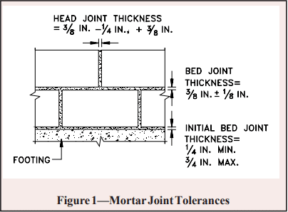
Unless otherwise required, footings should be carefully aligned so that the concrete masonry wall will be near the center line of the footing. Although the top surface of poured concrete footings should be relatively level, it should generally not be troweled smooth, as a slightly roughened surface enhances the bond between the mortar and concrete. Concrete footing design is governed by Building Code Requirements for Structural Concrete, ACI 318 (ref. 5), and concrete foundations are constructed with tolerances conforming to the requirements of Standard Specifications for Tolerances for Concrete Construction and Materials, ACI 117 (ref. 9).
BASEMENT WALLS
Basements are typically built as conditioned space so that they can be used for storage, work or living space. Because of this, water penetration resistance is of paramount importance to basement wall design and construction.
Following recommended backfill procedures will help prevent basement wall cracking during this operation. Walls should always be properly braced to resist backfill soil loads or have the first floor diaphragm in place prior to backfilling. Otherwise, a wall designed to be supported at the top may crack or even fail from overstressing the wall. Similarly, heavy equipment, such as bulldozers or cranes, should not be operated over the backfill during construction unless the basement walls are appropriately designed for the higher resulting loads.
The top 4 to 8 in. (102 to 203 mm) of backfill should be low permeability soil so rain water absorption into the backfill is minimized. Finished grade should be sloped away from the building.
Control joints are not typically used in foundation walls due to concerns with waterproofing the joint and the fact that shrinkage is less significant in below grade walls due to relatively constant temperature and moisture conditions. If warranted, horizontal joint reinforcement can be installed as a crack control measure.
The foundation drain shown in Figures 1 and 2 can also be located on the interior side of the footing, or on both sides if necessary. The drain should be placed below the top of the footing. The optional footing drain shown, such as 2 in. (51 mm) PVC pipe at 8 ft (2400 mm) on center, allows water on the interior to reach the foundation drain. Footing drains can either be cast into the footing or constructed using plastic pipes through the bottom of the first course of masonry, directly on top of the footing.
For reinforced construction (Figure 2), reinforcing bars must be properly located to be fully functional. In most cases, vertical reinforcement is positioned towards the interior face of below grade walls to provide the greatest resistance to soil pressures.
A solid top course on the below grade concrete masonry wall spreads loads from the building above and also improves soil gas and termite resistance. Where only the top course is to be grouted, wire mesh or another equivalent grout stop material can be used to contain the grout to the top course. Note that local codes may restrict the use of foam plastic insulation below grade in areas where the hazard of termite damage is high.
STEMWALLS FOR CRAWLSPACES
Unlike basements, crawlspaces are typically designed as unconditioned spaces, either vented or unvented. Several alternate crawlspace constructions are shown in Figures 3 and 4.
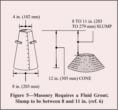
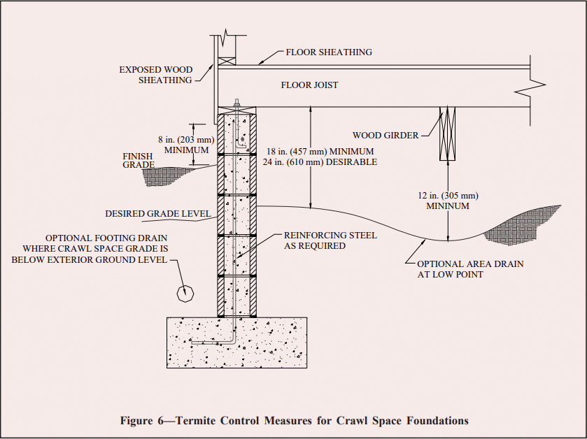
Although most building codes require operable louvered vents near each corner of a crawl space to reduce moisture buildup, research has shown that the use of a moisture retardant ground cover eliminates the need for vents in many locations (ref. 6). If the crawlspace is vented, the floor, exposed pipes and ducts are typically insulated. If unvented, either the walls or the floor above can be insulated. Unvented crawlspaces must have a floor covering to minimize moisture and, where applicable, soil gas entry. A vapor retarder (typically 6-mil (0.15 mm) polyethylene, PVC or equivalent) is good practice to minimize water migration and soil gas infiltration. A 2 1/2 in. (64 mm) concrete mud slab is generally used when a more durable surface is desired for access to utilities. A thicker concrete slab may be desirable, particularly if the crawlspace will be used for storage. A dampproof coating on the exterior crawlspace wall will also help prevent water entry into the crawlspace.
STEMWALLS FOR SLAB ON GRADE
A stemwall with slab on gradesupports the wall above and often also provides a brick (ref. 7) requires a foundation pier to have a minimum nominal thickness of 8 in. (203 mm), with a nominal height not exceeding four times its nominal thickness and a nominal length not exceeding three times its nominal thickness. Note that the International Building Code, (ref. 8) allows foundation piers to have a nominal height up to ten times the nominal thickness if the pier is solidly grouted, or four times the nominal thickness if it is not solidly grouted.
REFERENCES
Annotated Design and Construction Details for Concrete Masonry, CMU-MAN-001-03, Concrete Masonry and Hardscapes Association, 2003.
Concrete Masonry Basement Wall Construction, TEK 03-11, Concrete Masonry and Hardscapes Association, 2001.
Preventing Water Penetration in Below-Grade Concrete Masonry Walls, 19-03B, Concrete Masonry and Hardscapes Association, 2012.
Basement Manual: Design and Construction using Concrete Masonry, CMU-MAN-002-01, Concrete Masonry and Hardscapes Association, 2001.
Building Code Requirements for Structural Concrete, ACI 318 -02. American Concrete Institute, 2002.
2001 ASHRAE Handbook, Fundamentals. American Society of Heating, Refrigerating and Air-Conditioning Engineers, Inc., 2001.
Building Code Requirements for Masonry Structures, ACI 530-02/ ASCE 5-02/TMS 402-02. Reported by the Masonry Standards Joint Committee, 2002.
International Building Code. International Code Council, 2000.
Standard Specifications for Tolerances for Concrete Construction and Materials, ACI 117-90. American Concrete Institute, 1990.
Masonry is often specified because of its aesthetic versatility. Combining masonry units of different size, color and finish provides a virtually limitless palette. Often, exterior concrete masonry walls incorporate clay brick, or concrete masonry is used in clay brick walls as accent bands. The bands add architectural interest to the wall and can also help hide horizontal elements such as flashing and expansion joints. However, combining these two materials within one wythe of masonry requires special detailing due to their different material properties.
In general, all masonry walls should be designed and detailed to accommodate anticipated movement resulting from volume changes in the masonry materials themselves. For example, vertical control joints and horizontal joint reinforcement can be incorporated into concrete masonry walls to control cracking and still allow horizontal shrinkage of the concrete masonry units to occur without introducing undue stress into the wall. Similarly, clay masonry walls incorporate vertical and horizontal expansion joints to allow the clay to expand without distress. When both clay and concrete masonry units are used in the same masonry wythe, detailing is required to accommodate concrete masonry shrinkage and clay masonry expansion occurring side by side. Concrete masonry is a hydraulic cement product and as such requires water for cement hydration, which hardens the concrete. Therefore, concrete masonry units are relatively wet at the time of manufacture and from that time on tend to shrink as the units dry. Conversely, clay masonry units are very dry subsequent to firing during the manufacturing process and then tend to expand as they pick up moisture from the atmosphere and from mortar as they are laid. Without due consideration of these opposing movements, cracking can result. In veneers, the cracking is primarily an aesthetic issue, as any water that penetrates the veneer through cracks between the two materials drains down the cavity and is directed out of the wall via flashing and weep holes.
BANDING DETAILS
When detailing a wall to accommodate movement, the design goal is to allow the movement to occur (as restraint will cause cracking) while providing appropriate support. The recommendations that follow are based on a record of successful performance in many locations across the United States. These can be adjusted as needed to suit local conditions and/or experience.
In general, several strategies are used to accommodate movement. These include movement joints (control joints in concrete masonry and expansion joints in clay masonry); horizontal joint reinforcement to take tension due to concrete masonry shrinkage and help keep any cracks that occur closed; and sometimes horizontal joints to allow longitudinal movement. In veneers, it is particularly important that the band, as well as the wall panel above and below the band be supported by wall ties. Wall ties should be installed within 12 in. (305 mm) of the top and bottom of the band to help ensure the surrounding masonry is adequately supported.
In addition, using a lower compressive strength mortar helps ensure that if cracks do occur, they occur in the mortar joint rather than through the unit. Type N mortar is often specified for veneers, because it tends to be more flexible than other mortar types.
Concrete Masonry Band in Clay Brick Wall
Figure 1a shows a two-course high concrete masonry band in a clay brick exterior wythe of a cavity wall. With this type of construction, the following practices are employed to minimize the potential for cracking.
Horizontal joint reinforcement is placed in the mortar joints above and below the band to take stress from the differential movement in that plane. For bands higher than two courses, joint reinforcement should also be placed within the band itself at a spacing of 16 in. (406 mm) on center vertically. Ideally, the joint reinforcement and ties should be placed in alternate joints so that one does not interfere with placement of the other. Some designers, however, prefer placing joint reinforcement in every bed joint in the concrete masonry band, particularly if the aspect ratio of the band is high. In this case, a tie which accommodates both tie and wire in the same mortar joint should be used, such as a seismic clip type wall tie.
Although the detail in Figure 1a has demonstrated good performance in many areas of the United States, there are locations where use of bond breaks at the top and bottom of the band is preferred (see Figure 1b) A local masonry industry representative should be contacted for further information on which detail has been more successful in a given location.
Figure 1b shows a slip plane incorporated into the interfaces between the concrete and clay masonry to allow unrestrained longitudinal movement between the two materials. This can be accomplished by placing building paper, polyethylene, flashing or a similar material in the horizontal bed joints above and below the band. When hollow masonry units are used for the band, the slip plane below the band should incorporate flashing, so that any water draining down the cores of the band can be directed out of the wall at that point.
When slip planes are used, joint reinforcement should be incorporated into the concrete masonry band. The exposed mortar joint at the top and bottom of the band should be raked back and sealed with an appropriate sealant to prevent water penetration at these joints. Note that this construction is typically more expensive than the detail shown in Figure 1a.
In addition to joint reinforcement, reduced spacing of expansion joints in the wall is recommended to reduce the potential for cracking. Experience has shown that vertical expansion joints in the clay masonry should extend through the concrete masonry band as well, and be placed at a maximum of 20 ft (6.1 m) along the length of the wall. Although concrete masonry construction typically requires control joints rather than expansion joints, control joints should not be used in the concrete masonry band at the expansion joint locations.
Note that local experience may require reducing the expansion joint spacing to 16 ft (4.9 m). If brick vertical expansion joint spacing does exceed 20 ft (6.1 m), consider placing an additional vertical movement joint through the concrete masonry accent band near mid panel with joint reinforcement continuous through that joint. The continuous joint reinforcement in this location helps keep the clay brick above and below the band from cracking as the concrete masonry shrinks.
Bands only one course high must be detailed to incorporate joint reinforcement and wall ties in the joints above and below the band (see Figure 2).
When concrete masonry banding is used over a wood stud backup, similar provisions apply (see Figure 3). It is imperative that joint reinforcement be used in the concrete masonry band, even if it is not used in the surrounding clay brick masonry.
Clay Brick Band in Concrete Masonry Wall
The recommendations to control differential movement for clay brick masonry bands in concrete masonry are very similar to those for a concrete masonry band in clay brick veneer: joint reinforcement above and below the band and wall ties within the band. Seismic clip type wall ties are recommended, as they provide an adjustable wall tie and joint reinforcement in one assembly.
With this construction, it is imperative that the veneer control joint not contain mortar as it goes through effectiveness. Note that although control joints in structural masonry walls must permit free longitudinal movement while resisting lateral or out-of plane shear loads, veneers are laterally supported by the backup and do not require a shear key.
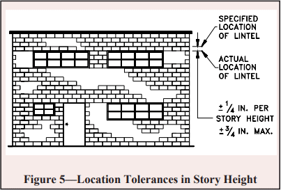
In single wythe construction as shown in Figure 5, flashing and weep holes are used above the accent band to facilitate removal of any water that may accumulate in the wall. The use of two reduced thickness concrete masonry units allows flashing to be placed within the wall without causing a complete horizontal bond break at the flashing.
In reinforced walls (Figure 5b), flashing and weeps are also used. On the wall interior, rather than using reduced thickness units, a full size unit is cut to fit to allow adequate space for the reinforcement and grout.
Estimating the quantity or volume of materials used in a typical masonry project can range from the relatively simple task associated with an unreinforced single wythe garden wall, to the comparatively difficult undertaking of a partially grouted multi-wythe wall coliseum constructed of varying unit sizes, shapes, and configurations.
Large projects, due to their complexity in layout and detailing, often require detailed computer estimating programs or an intimate knowledge of the project to achieve a reasonable estimate of the materials required for construction. However, for smaller projects, or as a general means of obtaining ballpark estimates, the rule of thumb methods described in this TEK provide a practical means of determining the quantity of materials required for a specific masonry construction project.
It should be stressed that the information for estimating materials quantities in this section should be used with caution and checked against rational judgment. Design issues such as non-modular layouts or numerous returns and corners can significantly increase the number of units and the volume of mortar or grout required. Often, material estimating is best left to an experienced professional who has developed a second hand disposition for estimating masonry material requirements.
ESTIMATING CONCRETE MASONRY UNITS
Probably the most straightforward material to estimate for most masonry construction projects is the units themselves. The most direct means of determining the number of concrete masonry units needed for any project is to simply determine the total square footage of each wall and divide by the surface area provided by a single unit specified for the project.
For conventional units having nominal heights of 8 in. (203 mm) and nominal lengths of 16 in. (406 mm), the exposed surface area of a single unit in the wall is 8/9 ft2 (0.083 m 2). Including a 5 percent allowance for waste and breakage, this translates to 119 units per 100 ft2 (9.29 m2) of wall area. (See Table 1 for these and other values.) Because this method of determining the necessary number of concrete masonry units for a given project is independent of the unit width, it can be applied to estimating the number of units required regardless of their width.
When using this estimating method, the area of windows, doors and other wall openings needs to be subtracted from the total wall area to yield the net masonry surface. Similarly, if varying unit configurations, such as pilaster units, corner units or bond beam units are to be incorporated into the project, the number of units used in these applications need to be calculated separately and subtracted from the total number of units required.
ESTIMATING MORTAR MATERIALS
Next to grout, mortar is probably the most commonly misestimated masonry construction material. Variables such as site batching versus pre-bagged mortar, mortar proportions, construction conditions, unit tolerances and work stoppages, combined with numerous other variables can lead to large deviations in the quantity of mortar required for comparable jobs.
As such, masons have developed general rules of thumb for estimating the quantity of mortar required to lay concrete masonry units. These general guidelines are as follows for various mortar types. Note that the following estimates assume the concrete masonry units are laid with face shell mortar bedding; hence, the estimates are independent of the concrete masonry unit width.
Masonry cement mortar Masonry cement is typically available in bag weights of 70, 75 or 80 lb (31.8, 34.0 and 36.3 kg), although other weights may be available as well. One 70 lb (31.8 kg) bag of masonry cement will generally lay approximately 30 hollow units if face shell bedding is used. For common batching proportions, 1 ton (2,000 lb, 907 kg) of masonry sand is required for every 8 bags of masonry cement. If more than 3 tons (2,721 kg) of sand is used, add 1/2 ton (454 kg) to account for waste. For smaller sand amounts, simply round up to account for waste. This equates to about 240 concrete masonry units per ton of sand.
Preblended mortar Preblended mortar mixes may contain portland cement and lime, masonry cement or mortar cement, and will always include dried masonry sand. Packaged dry, the mortars typically are available in 60 to 80 lb (27.2 to 36.3 kg) bags or in bulk volumes of 2,000 and 3,000 lb (907 and 1,361 kg).
Portland cement lime mortar One 94 lb (42.6 kg) bag of portland cement, mixed in proportion with sand and lime to yield a lean Type S or rich Type N mortar, will lay approximately 62 hollow units if face shell bedding is used. This assumes a proportion of one 94 lb (42.6 kg) bag of portland cement to approximately one-half of a 50 lb (22.7 kg) bag hydrated lime to 4 1/4 ft3 (0.12 m3) of sand. For ease of measuring in the field, sand volumes are often correlated to an equivalent number of shovels using a cubic foot (0.03 m3) box, as shown in Figure 1.
ESTIMATING GROUT
The quantity of grout required on a specific job can vary greatly depending upon the specific circumstances of the project. The properties and configuration of the units used in construction can have a huge impact alone. For example, units of low density concrete tend to absorb more water from the mix than comparable units of higher density. Further, the method of delivering grout to a masonry wall (pumping versus bucketing) can introduce different amounts of waste. Although the absolute volume of grout waste seen on a large project may be larger than a comparable small project, smaller projects may experience a larger percentage of grout waste.
Table 3 provides guidance for the required volume of grout necessary to fill the vertical cells of walls of varying thickness. Additional grout may be necessary for horizontally grouting discrete courses of masonry. Note that walls constructed of 4-in. (102-mm) masonry units are not included in Table 3. Due to the small cell size and difficulty inadequately placing and consolidating the grout, it is not recommended to grout conventional 4-in. (102-mm) units.
Tables 4 and 5 contain estimated yields for bagged preblended grouts for vertical and horizontal grouting, respectively.
REFERENCES
Kreh, D. Building With Masonry, Brick, Block and Concrete. The Taunton Press, 1998.
Annotated Design and Construction Details for Concrete Masonry, CMU-MAN-001-03, Concrete Masonry & Hardscapes Association, 2003.
For masonry construction, productivity is typically thought of as the number of concrete masonry units placed per unit of time. This production rate is influenced by many factors, some of which can be controlled by the mason and others which are beyond the mason’s control.
PRODUCTIVITY RATES
Ideally, concrete masonry productivity rates should be compiled by masonry estimators, based on records of completed jobs. Published productivity rates, such as those shown in Figure 1 and Table 1, should be used as guidelines only.
The following sections discuss some of the various factors that can impact masonry productivity. In addition to these, productivity rates can vary with unit size and concrete density, mortar workability, masonry bond pattern, number and type of wall openings, amount of reinforcement and wall size.
As illustrated in Figure 1, concrete ma-primarily in running bond, other bond patterns often require more time to lay. For example, stack bond has been estimated to decrease productivity by about 8% over comparable running bond productivity rates (ref. 4).
Bond pattern can also affect productivity. Because masonry crews are accustomed to laying concrete masonry primarily in running bond, other bond patterns often require more time to lay. For example, stack bond has been estimated to decrease productivity by about 8% over comparable running bond productivity rates (ref. 4).
IMPACT OF QUALITY ON PRODUCTIVITY
The overall quality of the project can influence the masonry productivity. Quality construction includes:
pre-bid and pre-construction conferences,
proper design,
attention to planning and layout,
quality materials,
adequate jobsite and
proper installation.
A project with these ingredients will also be conducive to a very productive jobsite.
Pre-Bid and Pre-Construction Conferences
Pre-bid and pre-construction conferences should be held and attended by all parties involved in the masonry work including the owner’s representative, the architect/engineer, the contractor, the construction manager, the masonry material suppliers and the mason contractor. This facilitates good communication prior to the commencement of work and prior to the development of any misunderstandings. Clear communication minimizes delays due to factors such as lastminute changes and errors.
Proper Design
Quality design means that the designer has:
designed and detailed a project that is constructible,
developed plans and specifications that are sufficient for construction and are complete with the proper code and standards referenced,
reviewed the plans, specifications and structural drawings to eliminate conflicting words and conflicting details,
included the input of a quality mason contractor, and
incorporated all masonry materials into CSI Division 4. (Often, some mason materials are found in division 7. If all of the mason’s work is placed into Division 4, it enhances communication with the masonry team and has a better chance of being properly incorporated into the job.) Similar to the pre-bid and pre construction conferences, a comprehensive set of plans and specifications will help enhance productivity because it will reduce or eliminate time spent correcting misunderstandings and errors.
A complete set of plans and specifications will include a copy of Building Code Requirements for Masonry Structures and Specification for Masonry Structures (refs. 1, 2), the national consensus standards for masonry design and construction. In addition, applicable ASTM standards should be included for specifying masonry materials.
Planning and Layout
Attention to planning of the building itself and of construction sequencing and scheduling can impact masonry productivity.
Concrete masonry structures can be constructed using virtually any layout dimension. However, for maximum construction efficiency and economy, concrete masonry elements should be designed and constructed with modular coordination in mind. Modular coordination is the practice of laying out and dimensioning structures to standard lengths and heights to accommodate modular sized building materials. Standard concrete masonry modules are typically 8 in. (203 mm) vertically and horizontally, but may also include 4in. (102 mm) modules for some applications. These modules provide the best overall design flexibility and coordination with other building products such as windows and doors. Typically, masonry opening widths for doors and windows should be 4 in. (102 mm) larger than the door or window width. This allows for 2 in. (51 mm) on each side of the opening for framing. Masonry opening heights for windows typically are 8 in. (203 mm) greater than the window height. This opening size allows for 2 in. (51 mm) above and below for framing and 4 in. (102 mm) for installing a sill at the bottom of the window. Masonry opening door heights are 2 in. (51 mm) greater than the door height, which leaves 2 in. (51 mm) for the door framing. Figure 2 illustrates these opening sizes.
Thus, door and window widths of 28 in., 36 in., 44 in., and 52 in. (711, 914, 1118 and 1,321 mm), and so on in 8 in. (203 mm) increments, are modular and would not require cutting of the masonry. Modular window heights are any multiple of 8 in. (203 mm), with a masonry window opening 8 in. (203 mm) greater than the height of the window if a 4 in. (102 mm) sill will be used. Similarly, a modular door height is 2 in. (51 mm) less than any multiple of eight. Thus, an 86 in. (2,184 mm) high door, which fits into an 88-in. (2,235 mm) high masonry opening, has a modular height.
Note that products are available in some locations to accommodate 6’ 8” (2,032 mm) doors in masonry walls without the need for cutting the masonry units. These include precast lintels with a 2 in. (51 mm) notch which provides the necessary 6’ 10” (2,083 mm) masonry opening to accommodate the door and frame. In other areas, door frames are available with a 4 in. (101.6 mm) header which would allow a 6’ 8” (2,032 mm) door to fit into 7’ 4” or 88 in. (2,235 mm) high masonry opening.
Nonmodular layouts may require additional considerations for items such as using nonstandard units or saw cutting masonry units and maintaining bond patterns. Additionally, other construction issues may arise, such as placement of jamb reinforcement and adequate grout consolidation within small core spaces. The end product typically is more difficult to construct, produces more waste and is more costly.
Similarly, coordinating the placement of pipes, ducts, chases and conduits to align them with hollow masonry cores can reduce the need to saw-cut masonry units.
Steel congestion in reinforced masonry can slow productivity. Placing too many reinforcing bars in too small a space makes it difficult to place the steel and to provide adequate grout coverage. Specification for Masonry Structures (ref. 3) requires 1/4 in. (6.4 mm) clear space between the reinforcing bar and the masonry for fine grout and 1/2 in. (13 mm) clear space for coarse grout.
Sample panels reduce misunderstandings and provide an objective indicator of the intended construction practices. They help ensure all parties understand the range of materials, methods and workmanship acceptable on the job. Sample panels are typically at least 4 ft by 4 ft (1.22 x 1.22 m) and should contain the full range of unit and mortar colors. Selecting units of all one shade for the sample panel will not accurately reflect the completed work. Instead, units should be randomly selected as they would in the project construction. Cleaning procedures, sealant application and all other procedures should be performed on the sample panel so that their acceptability can be judged as well. The sample panel should remain in place throughout construction as a point of reference.
For maximum productivity, timely delivery of the units, mortar, grout and other masonry materials will help expedite the job. In addition, schedule masonry work to avoid times of the year particularly subject to freezing temperatures or prolonged rains whenever possible. Although masonry construction can take place during hot, cold and wet weather conditions, special construction procedures may be warranted in some cases to ensure the masonry quality is not impacted by the weather. More detailed information on these construction procedures can be found in All-Weather Concrete Masonry Construction (ref. 4).
Quality Materials
Masonry materials have a successful history of meeting applicable specifications and project requirements. Ensuring that the materials used are as specified helps keep the masonry construction on track. ASTM standards for masonry units, for example, specify dimensional tolerances for the units. Units meeting the ASTM tolerances will be easier to place, and allow the mason to more easily maintain level and alignment. Similarly, units without excessive chippage (a characteristic also governed by ASTM standards) allow placement without the need for sorting the product for quality—an activity that reduces overall productivity.
Jobsite
A quality jobsite helps productivity by including ample space for the mason subcontractor to work and having easy access to the masonry supplies. This includes having:
undisturbed space for building the sample panel(s),
a defined and ample-sized area for materials and supplies, and
a defined and ample-sized area for sampling and testing procedures as required for the project.
Proper Installation
In addition to the factors cited above, quality installation requires:
an ample number of qualified craftsmen,
qualified and sufficient supervision, and
the right equipment for the job.
There have been some marvelous developments in products and equipment to assist masons and hence increase masonry productivity. For example, newer fork lifts often have increased capacity, a single boom which increases visibility, are more maneuverable, have higher load ratings and higher extensions. Other equipment advances that can enhance productivity include portable hand-held lasers that work in numerous directions simultaneously, electric portable winches and power (crank-up or hydraulic) scaffolding. Products that are easier for the mason to install, such as self-adhesive flashings and pre-formed flashing end dams, can also impact masonry productivity.
Choice of mortar can also impact productivity. Masonry and mortar cements provide more consistency because all of the cementitious ingredients are premixed. Premixed mortars, which include the sand mixed with the appropriate cement, are also available in silos or in mixers or blenders. Premixed mortars can improve mortar quality control and uniformity and can also increase productivity by eliminating the need for job site mixing.
In some cases, work by other trades can also impact masonry productivity. For example, poured concrete foundations or footings which do not meet their tolerances may require the mason to saw-cut the first course of block, or take some other measure, to compensate.
REFERENCES
Building Code Requirements for Masonry Structures, ACI 530-02/ASCE 5-02/TMS 402-02. Reported by the Masonry Standards Joint Committee, 2002.
Specification for Masonry Structures, ACI 530.1-02/ ASCE 6-02/TMS 602-02. Reported by the Masonry Standards Joint Committee, 2002.
Concrete masonry screen walls are used in every part of every country on the globe, on every conceivable style of building, and for a wide variety of purposes. Created originally as a functional building element, the screen wall combines privacy with observation, interior light with shade and solar heat reduction, and airy comfort with wind control for both interior and exterior applications. Curtain walls, fences, sun screens, and room dividers are just a few of the limitless applications for a concrete masonry screen wall. The scope of this TEK focuses on the design and detailing of non-loadbearing concrete masonry screen walls. For loadbearing screen wall applications, users are referred to the applicable engineering analysis provisions of TMS 402 (Ref. 5).
Extra attention to the design of screen walls is warranted because of the relatively high percentage of open area in their face. The open area is created usually by the use of special screen units with decorative openings in their face. Screen walls should be designed to resist wind pressure and seismic forces to which they are exposed to while providing a durable and attractive architectural finish. Strength and stability is provided by: (1) incorporating steel reinforcement (either conventional reinforcing bars, bed joint reinforcement, and/or anchors); (2) limiting the clear span of screen walls; and/or (3) providing a separate support system capable of carrying lateral loads from the assembly to the backup support(s).
MATERIALS
Screen Wall Units – Due to the virtually limitless number of shapes and sizes for concrete masonry screen wall units, designers are encouraged to check on the availability of any specific shape during the early planning stages of a project. Some shapes are available only in certain localities and others may be restricted by patent or copyright. Figure 1 illustrates a general overview of some of the shapes that may be encountered for screen wall design. Note that these unit configurations can come in various thicknesses depending upon availability.
Despite screen wall units being used predominately in onloadbearing applications, they still should be of high quality for their intended construction. At a minimum, concrete masonry units used for screen walls should meet the requirements of ASTM C90, Standard Specification for Loadbearing Concrete Masonry (Ref. 1). Verification of unit properties should be in accordance with ASTM C140, Standard Test Methods for Sampling and Testing Concrete Masonry Units and Related Units, Annex A1 (Ref. 2). Due to their unique configuration full-size testing of screen wall block is not feasible, thus requiring that coupons be removed from the screen wall block for compressive strength testing. The coupon must meet the specimen size requirements of a height to thickness ratio equal to two (2) to one (1) and a length to thickness ratio equal to four (4) to one (1). In some situations, the length requirement for a specimen may not be able to be attained. In these cases, the length should be greater than or equal to the height of the specimen.
When tested in accordance with ASTM C140, screen units must attain a minimum average net area compressive strength of 2000 psi (13.7 MPa) based on three units tested. In addition to the above compressive strength requirements, the recommended minimum thickness of any part of the screen wall unit should not be less than 3/4 inches (19 mm).
Figure 2 presents a visual representation of where the coupon for a given screen block wall unit can be extracted. Per ASTM C140, the height of the coupon must be in the same orientation as the height of the screen block when it is placed.
Further information on ASTM C90, ASTM C140, and concrete masonry units can be found in CMU-TEC-001-23 (Ref. 7), TEK 18 01D (Ref. 16), and TEK 18-02C (Ref. 17).
Mortar – ASTM C270, Standard Specification for Mortar for Unit Masonry (Ref. 3), contains non-mandatory recommendations for the type of mortar to use for various applications. Type N mortar is the recommended type for exterior and interior nonloadbearing walls, which would encompass screen walls.
Alternatives such as Type S or M mortar can be used where the design variable or exposure conditions warrant.
For additional information on mortar, see TEK 09-01A (Ref. 9).
Grout – Grout for embedding steel reinforcement in horizontal or vertical cells should comply with ASTM C476, Standard Specification for Grout for Masonry (Ref. 4).
For additional information on grout, see TEK 09-04A (Ref. 10) and TEK 18-08A (Ref. 9).
Reinforcement and Anchor – Reinforcing steel comes in three different forms for screen walls: 1) Steel wire reinforcement that is prefabricated consisting of cold-drawn wire, 2) reinforcing bars, and 3) anchors. During the design, the designer must be cognizant of the cover and protective coating requirements for the steel. These requirements are largely dependent on the type of weather the screen wall will encounter during the life of the assembly and these requirements may affect the design of the wall.
For additional information on reinforcement steel, see TEK 12-01B (Ref. 12), TEK 12-02B (Ref. 13), TEK 12-04D (Ref. 14), and TEK 12-
06A (Ref. 15).
DESIGN
The design of a screen block wall depends upon a number of factors: function, location (exterior or interior), aesthetic requirements, and provisions of local building codes. They are used extensively for the following types of construction: (1) interior partitions, (2) free-standing walls supported on their own foundations, (3) and enclosed panels in masonry walls or external frames.
Screen wall partitions are designed as non-loadbearing panels with primary consideration given to adequate anchorage at panel ends and/or top edge, depending upon the type of lateral support furnished. Free-standing walls include such assemblies as fences and other exterior non-loadbearing screens that receive lateral stability from a structural frame braced to an adjacent structure or designed as a cantilever from the foundation.
Non-loadbearing screen walls should have a minimum nominal thickness of 4 in. (102 mm). Based on the nominal thickness of the unit and design method to be used, Table 1 was derived to determine the maximum height or length that can be built for a screen wall that has its units placed on a full mortar bed. This chart has been broken down into four separate distinct design categories: (1) Vertically Spanning per Allowable Stress Design (ASD) method, (2) Horizontally Spanning per Allowable Stress Design (ASD) method, (3) Vertically Spanning per Strength Design method, and (4) Horizontally Spanning per Strength Design method.
The use of Table 1 requires the following:
1) The tables assume the wall is either vertically spanning (supported at the top and bottom of the wall) or horizontally spanning and laid in a running bond (supported at the sides of the wall). If the wall is to be horizontally spanning using a bond pattern other than running bond, then the table is not valid and cannot be used. 2) The table assumes the screen wall units are placed on a full mortar bed with no open spaces between units. 3) The wind pressure and seismicity pressure expected to be encountered for the wall must be known. 4) The design pressure can be from either seismic or wind out-of place loading. 5) The screen walls are not designed to carry axial loads other than their own weight and are not part of the lateral force resisting system (shear walls).
Wind and seismic loads are typically the most frequently encountered external force that will interact with the wall. Wind pressures are calculated using the provisions ASCE 7, Minimum Design Loads for Buildings and Other Structures (Ref. 6) for open signs or lattice structures thus taking into account the open area of the screen wall. Seismic forces are also determined in accordance with ASCE 7 for architectural components based upon the installed weight of the screen wall. Based on the calculated loads, the designer should use the higher of the two loads to determine the maximum height to thickness or length to thickness ratio for a given design method.
For example, when building a horizontally spanning screen block wall with nominal 4 in. (102 mm) thick units placed with Type S portland cement mortar in an area that encounters 15 psf (0.718 kPa) wind pressure, the maximum length span of the screen wall is 12 ft (3.66 m) using the ASD method. Determined as follows:
Per Table 1a for a horizontally spanning wall,
Another example, when building a vertically spanning screen block wall with nominal 5 in. (127 mm) thick units placed with Type N portland cement mortar in an area that encounters 40 psf (1.915 kPa) wind pressure, the maximum height span of the screen wall is 6 ft 8 in. (2.03 m) using the Strength Design method. Determined as follows:
Per Table 1b for a vertically spanning wall,
Adequate anchorage should be provided between screen walls and lateral supports, and the supports should be designed to transfer loads to the structure and into the ground. Examples of anchorage of free-standing screens to their supporting framework is accomplished by various means as illustrated in Figure 3, with alternate support conditions shown in Figures 4, 5, 6, and 7. Lateral support may be obtained from cross walls, piers, columns, posts, or buttresses for horizontal spans, and from floors, foundations, roofs, or spandrel beams for screen walls spanning the vertical direction. Consideration should be given to expansion caused by temperature change and by deflection under load when screen wall panels are enclosed in a structural framing system.
CRACK CONTROL
The use of steel reinforcement is permitted where it can be embedded in mortar joints, in bond beam courses, or grouted into continuous vertical cells. Horizontal bed joint reinforcement consisting of two No. 9 gauge wires or equivalent, placed 16 inches o.c. is recommended when screen wall units are laid in stack bond. Horizontal bed joint reinforcement is not required for running bond masonry; however, the use of it helps with crack control in a masonry wall.
Ladder-type joint reinforcement and truss-type bed joint reinforcement are both acceptable forms of joint reinforcement as the reinforcement will lie on a solid face and not interfere with vertical reinforcement.
Control joints can be used at the discretion of the designer to mitigate cracking potential. Figures 6 and 7 illustrate options for supporting screen walls while incorporating control joints. For more information on crack control see, CMU-TEC-009-23 (Ref. 11).
REFERENCES
Standard Specification for Loadbearing Concrete Masonry Units, ASTM C90-15. ASTM International, Inc., 2015.
Standard Test Methods for Sampling and Testing Concrete Masonry Units and Related Units, ASTM C140-15. ASTM International, Inc., 2015.
Standard Specification for Mortar for Unit Masonry, ASTM C270-14a. ASTM International, Inc., 2014.
Standard Specification for Grout for Masonry, ASTM C476-10. ASTM International, Inc., 2010.
Building Code Requirements for Masonry Structures, TMS
The Masonry Society, 2016.
Minimum Design Loads and Associated Criteria for Buildings and Other Structures, ASCE 7. American Society of Civil Engineers, 2016.
Concrete Masonry Unit Shapes, Sizes, Properties, and Specifications, CMU-TEC-001-23, Concrete Masonry & Hardscapes Association, 2023.
Diaphragm walls are composed of two wythes of masonry with a large cavity or void. The wythes are bonded together with masonry ribs or crosswalls in such a way that, structurally, the wythes function compositely—as though the entire thickness is effectively solid.
Figure 1 shows a stone-clad university building with reinforced concrete masonry diaphragm walls, used to recreate the campus’ Gothic architecture. The use of reinforced diaphragm walls allowed support of the tall sidewalls and gable ends.
Figure 2 shows a cross-section of a typical diaphragm wall. The reinforced wythes can be fully or partially grouted. The exterior face can be constructed with a weathering face, like a conventional single wythe wall, or finished with a veneer. The voids can be used for placement of utilities and/or insulation.
This TEK discusses construction considerations for diaphragm walls: TEK 14-24, Design of Reinforced Concrete Masonry Diaphragm Walls, (ref. 1) covers the structural design.
CONSTRUCTION ADVANTAGES
Reinforced diaphragm walls present several construction benefits. These include:
As shown in Figure 1, thick walls can be created efficiently using standard units bonded together. Thicker walls can be used to create taller walls.
The wall can have exposed finished surfaces both inside and out. In addition, those finishes can be different because they are created by two different masonry wythes and can, therefore, feature different unit types/sizes/colors.
The wall construction proceeds very much as conventional single wythe or cavity wall construction.
The exterior wythe can be constructed with a veneer.
The large interior voids allow for easy placement of utilities and/or insulation.
KEY CONSTRUCTION FEATURES
Construction Sequence
The construction sequence for diaphragm walls can vary based upon how the ribs are interconnected with the two wythes. Building Code Requirements for Masonry Structures (ref. 2), referred to as TMS 402, Section 5.1.1.2.5 provides three methods for connecting intersecting walls to allow shear transfer:
At least fifty percent of the masonry units at the interface must interlock. This means the ribs could be constructed in running bond with every other course interlocking with the wythes. Thus, the wythes and the ribs would be constructed concurrently.
Walls must be anchored by steel connectors grouted into the wall and meeting the following requirements: (a) Minimum size: 1/4 in. x 1-1/2 in. x 28 in. (6.4 x 38.1 x 711 mm) including 2-in. (50.8-mm) long, 90-degree bend at each end to form a U or Z-shape. (b) Maximum spacing: 48 in. (1,219 mm). Thus, it is possible to build the ribs separately from the wythes, which provides significant flexibility in construction.
Intersecting reinforced bond beams must be provided at a maximum spacing of 48 in. (1,219 mm) on center. The area of reinforcement in each bond beam must be not less than 0.1 in.2 per ft (211 mm2/m) multiplied by the vertical spacing of the bond beams in feet (meters). Reinforcement must be developed on each side of the intersection.
Again, this provides flexibility in sequencing the wall construction. However, the grouting must be done simultaneously with the wythe construction.
Masonry Bond
TMS 402 Section 5.1.1.2.1 requires that the masonry at intersecting walls be laid in running bond for composite action between wythes to be effective. This requirement controls the entire construction of a diaphragm wall and mandates running bond for both the wythes and the ribs.
Reinforcement
Vertical reinforcement is typically placed in the cells of the wythes as is done in single-wythe construction. Posttensioning can be placed either in the cells of the wythes or within the void itself. If placed within the void and laterally restrained tendons are specified, tendon restraints must be fabricated. TEK 03-14, Post-Tensioned Concrete Masonry Wall Construction (ref. 3) provides a more detailed overview. Depending on the project’s seismic and/or loading requirements, horizontal reinforcement can be placed in either grouted bond beams or in the bed joints of the wythes and ribs. Horizontal bond beams are beneficial in that they can also serve as the interlock between the ribs and wythes, as well as shear reinforcement for the ribs.
Ribs (Crosswalls)
The structural design will determine whether or not the ribs require vertical reinforcement. The interlock with the wythes transfers shear forces across the intersections, and the vertical reinforcement in the wythes acts as the total wall reinforcement.
Wall Grouting
The requirement for full or partial wall grouting is a design decision. Any cells or bond beams with reinforcement must be grouted. The need for additional grouting is determined based on the design requirements. Both low-lift and high-lift grouting techniques are suitable to diaphragm walls. See TEK 03-02A, Grouting Concrete Masonry Walls, (ref. 4) for more detailed information.
Water Management
Strategies for water penetration resistance of conventional masonry walls depend on whether the wall is singlewythe or a cavity wall. Water penetration resistance for the exterior wythe of a diaphragm wall follows the strategies employed for single wythe construction. If the exterior wythe has a veneer and cavity, it is flashed and weeped the same way as a single wythe masonry cavity wall. With no veneer and cavity, the exterior wythe of a diaphragm wall is flashed and weeped the same way as a similarly constructed partially grouted single wythe wall. Flashing and weeps are not necessary if the exterior wythe is solid grouted.
Figure 3 shows a typical wall base detail for a diaphragm wall with an exterior veneer and cavity. The cavity between the exterior diaphragm wythe may contain insulation and an air/moisture barrier, as required. The veneer is anchored to the exterior wythe of the diaphragm wall and is weeped and flashed. TEK 19-05A, Flashing Details for Concrete Masonry Walls, (ref. 6) provides additional details applicable to this construction.
Figure 4 shows a wall base detail applicable to an exterior diaphragm wythe without a cavity and veneer. TEK 19-02B, Design for Dry Single Wythe Concrete Masonry Walls, (ref. 7) provides additional details for single wythe construction.
Openings through diaphragm walls, roof/floor intersections, etc. are also flashed and weeped similar to conventional concrete masonry walls.
Top of the Wall
Diaphragm walls require closure at the top to transfer vertical loads and close off the void. Figure 5 shows one common detail for capping the walls. The cast-in-place capping slab at the top takes the place of what would normally be bond beams in single-wythe walls. For post tensioned walls, the top slab provides a convenient anchorage point for the tendons.
Utilities and Insulation
The voids offer several opportunities not common in masonry walls. They provide chases for duct work and utilities with minimal cutting of the units and allow for additional insulation if desired. Diaphragm walls can be insulated on the exterior, by using a veneer and insulated cavity, or by using an exterior insulation system. They can also be insulated on the interior, using furring, insulation and gypsum wallboard. When insulation is placed in the voids, however, the ribs produce a large thermal bridge, reducing the effectiveness of the insulation. 06-11A, Insulating Concrete Masonry Walls, (ref. 5) provides more detailed information.
Openings
Constructing openings in diaphragm walls is also very similar to single-wythe walls (see Figure 6). The entire void should be spanned/filled at the opening and the exterior wythe flashed above (as appropriate), as shown in Figure 4. Figure 6 Option 1 shows a reinforced concrete slab that has been designed as a header for the opening. Figure 6 Option 2 has lintels to support the wythes over the opening. The void at the headers and sills is infilled with a nonmasonry material, such as exterior gypsum sheathing. The jambs should be infilled with masonry wherever they don’t already align with the ribs. Note that Figure 6 does not show flashing that may be necessary.
Control Joints
Control joints are provided in concrete masonry walls to control cracking primarily from movement due to shrinkage and thermal effects. In diaphragm walls, the ribs will tend to restrict some of that movement, however, because there is currently no research to quantify these effects, current practice is to place control joints at intervals based upon CMU-TEC-009-23, Crack Control Strategies for Concrete Masonry Construction, (ref. 8). TEK 14-24 discusses these criteria and provides an example for determining control joint spacing for a diaphragm wall.
Although the inner wythe will generally be exposed principally to shrinkage with only minor thermal effects, it is common to place control joints in the same locations and to provide similar shrinkage reinforcement in both wythes.
Figure 7 shows two methods of creating control joints in a diaphragm wall. Option 1, with ribs on both sides of the control joint, does a better job keeping water out of the void than Option 2 because a failure of the sealant would allow water to penetrate between the ribs, rather than into the void itself. The control joints in both wythes should be sealed for water protection.
CMU-TEC-009-23 contains additional control joint constructions/details that can also be used on diaphragm walls, including fire-rated joints and control joints that allow shear transfer.
SUMMARY
Diaphragm walls provide several beneficial features and are applicable to a wide variety of projects. Constructing reinforced concrete masonry diaphragm walls uses methods and techniques commonly known to most masons. The added thickness of the wall provides some variations in the overall reinforcement and layout concepts but the techniques are typical for masonry.
REFERENCES
Design of Reinforced Concrete Masonry Diaphragm Walls, TEK 14-24. Concrete Masonry & Hardscapes Association, 2014.
Building Code Requirements for Masonry Structures, TMS 402-16, Reported by The Masonry Society 2016.
Prestressing is the general term used when a structural element is compressed prior to being subjected to building loads. This initial state of compression offsets tensile stresses from applied loads. Post-tensioning is a specific method of prestressing where tendons are stressed after the wall has been placed. The other type of prestressing, called pretensioning, involves tensioning the tendon prior to construction of the masonry. Because virtually all prestressed masonry built to date has been post-tensioned, the two terms are often used interchangeably as they apply to this form of masonry design and construction.
Post-tensioned concrete masonry walls have been built for schools, retail, manufacturing, highway sound barriers, warehouses and other types of structures. In addition, posttensioning has been used to strengthen and repair existing masonry walls. This TEK addresses new concrete masonry walls laid in running bond and built with unbonded vertical posttensioning tendons. Post-Tensioned Concrete Masonry Wall Design, TEK 14-20A (ref. 1) addresses the structural design of vertically post-tensioned walls.
POST-TENSIONING
In post-tensioned construction, hollow concrete masonry units are laid conventionally and prestressing tendons are either placed in the concrete masonry cells or in the cavity between multiple wythes. Current design codes (ref. 3) typically address post-tensioning of masonry walls laid in running bond. The cells or cavity containing the tendons may or may not be grouted. Grouting helps increase cross-sectional area for shear and compressive resistance, but increases construction cost and time.
Prestressing tendons are either installed during wall construction, or access ports are left in the walls so the tendons can be slipped in after the walls are completed. In either case, the tendons are tensioned only after the walls have cured for approximately three to seven days.
MATERIALS
Construction of a post-tensioned wall proceeds similarly to that of conventional masonry. The materials are the same, with the addition of hardware to develop the posttensioning forces, steel prestressing tendons which can be wires, bars or strands, and sometimes prestressing grout.
Concrete Masonry Units
Open-ended (Aand H-shaped) concrete masonry units (Figure 1) are particularly suited to post-tensioned masonry, as these units can be placed around the tendons without having to lift the units over the tendons. While these two-core units are commonly used, proprietary units are also being developed that are specifically intended for use with tendons.
The net area strength of concrete masonry units must be at least 1,900 psi (13.1 MPa) per Standard Specification for Loadbearing Concrete Masonry Units (ref. 2). However, stronger units are often specified for post-tensioned walls to utilize the higher compressive strength.
Mortar and Grout
Type S mortar is commonly used for conventional loadbearing masonry, and Type S is a good choice for posttensioned masonry as well. Higher early strength mortars can accommodate earlier stressing.
Because mortar must be placed on concrete masonry webs adjacent to grouted cores to contain the fluid grout, full mortar bedding is sometimes specified when grout is used. Mortar bedding is a design issue as well, as the section properties of a wall with face shell mortar bedding are different from those of a fully bedded wall.
Because this TEK addresses unbonded tendons only, the grout discussed here is conventional grout (ASTM C 476, ref. 6), not prestressing grout. Prestressing grout is only used with bonded tendons. Encasing tendons in conventional grout restrains the tendons, but they are still considered unbonded.
Tendons
In the United States, tendons are usually high-strength bars joined by couplers, although Building Code Requirements for Masonry Structures (ref. 3) also allows steel strands or wires to be used. Couplers allow the use of shorter bars which minimizes the height of lifting. To date, there are no code provisions for tendons which are not steel.
Important features of the tendons are their size, strength, and relaxation characteristics. Most tendons currently available in the United States are bars between 7/16 and 1 in. (11 and 25 mm) in diameter, with strengths between 60,000 and 100,000 psi (413 and 690 MPa), depending on the supplier. Steel strand tendons are generally 270,000 psi (1,860 MPa). Tendons are usually placed in hollow cells of masonry units with little or no grouting, except for certain shear walls (these must be identified on the design drawings). In addition, the open-ended units shown in Figure 1 must be grouted to meet minimum web requirements in ASTM C 90 (ref. 2).
Tendon Corrosion Protection
Tendons must be protected from moisture deterioration, and the design documents should indicate the type of protection required. Tendons in walls with a likelihood of high moisture levels (single wythe exterior walls in areas of high humidity and interior walls around swimming pools, locker rooms, etc.) must have corrosion protection in addition to that provided by the masonry cover, such as hot-dipped galvanizing (ref. 3). In practice, most prestressing tendons are supplied with a hotdipped galvanized coating. It is considered good practice to use additional corrosion protection, such as flexible epoxy-type coatings, for tendons in moist environments.
Grouting
While the need for grouting is minimized compared to conventionally reinforced walls, grout is still needed for mild reinforcement, anchorages for the tendons, such as in bond beams, and tendon restraints.
Anchorages
Each tendon is anchored at the foundation and extends to the top of the wall. Building Code Requirements for Masonry Structures (ref. 3) requires that tendons be anchored by mechanical embedments or bearing devices or by bond development in concrete. Tendons can not be anchored by bond development into the masonry. The foundation anchorage is embedded in the wall or footing while the top anchorage utilizes a special block, a precast concrete spreader beam or a grouted bond beam.
Unless the design documents call out specific bottom anchors, the contractor must select the anchor appropriate to the conditions. The cast-in-place bottom anchor (Figure 2a) is preferred for shear walls and for fire walls. While they are the best anchors for capacity, cast-in-place anchors are the most difficult to align. Cast-in-place anchors are often set by the foundation contractor, not the mason. Thus, quality control is a concern with these anchors.
The mason controls bottom anchor placement when either adhesive anchors are installed in the foundation (Figure 2c), or when an anchor is used which does not rely on the foundation for support (Figure 2b). If the anchor in Figure 2b is used, foundation dowels are grouted into the wall to lock it in place. In some instances, tendons can also begin at an upper floor and not at the foundation. In this case, the foundationless anchor is used with a bond beam, similar to Figure 2b.
The mechanical post-installed anchors can be used for nearly all applications, while the adhesive type should not be used for fire walls.
CONSTRUCTION
Key steps of post-tensioning concrete masonry walls include: selecting and setting the bottom anchorages; installing the tendons; selecting and setting the top anchorages; and a tensioning the tendons.
Bottom Anchors
Bottom anchors are most critical to the proper construction of post-tensioned walls. Alignment is essential to ensure that the tendons are placed exactly as intended.
Tendons
Tendons are usually placed concentric with the wall. However, they may be placed off-center to counteract bending moments due to eccentric vertical forces or lateral forces from a single direction. However, tendons should not be placed such that tensile stresses develop in the wall due to the combination of prestressing force and dead load.
Laterally-unrestrained tendons are free to move within the cell or cavity and are the simplest to construct. Laterally restrained tendons are not free to move within a cell or cavity. Restraint is accomplished by grouting the full height of the tendon or by providing intermittent restraints—either grout plugs or mechanical restraints—at the quarter points of the wall height.
Placing tendons is much like that of mild reinforcement. They may be installed after the masonry is constructed provided the design allows laterally-unrestrained tendons. If laterally restrained tendons are required, the tendon placement should proceed simultaneously with the masonry to allow the restraints to be installed unless the cells will be grouted.
Tendon positioners (see Figure 3) are useful to maintain the tendon location within the wall during construction of the masonry. Positioners may also function as restraints if their capacity is determined by testing.
In all details, the tendons must be able to slip freely. If grout encases the tendon either totally or at restraints or bond beams, a bond breaker such as poly tape should be used to allow the tendon to slip.
Tendons can also be either bonded or unbonded. Bonded tendons are encapsulated by prestressing grout in a corrugated duct which is bonded to the surrounding masonry by grout. Both the prestressing grout inside the duct and the grout around the duct must be cured before the tendons are stressed. Thus, bonded tendons are also laterally-restrained. All other tendons are unbonded. However, unbonded tendons may be either laterally-restrained or unrestrained. Walls with laterally unrestrained and unbonded tendons do not require grouting and are generally the most economical to construct. However, the wall performance will not be as good as with laterally restrained tendons. The designer must specify which system will be used.
For some conditions, primarily seismic, grouted conventional reinforcement is used in addition to post-tensioning tendons to provide minimum requirements of bonded reinforcement. However, post-tensioned walls are most economical when the grouting is minimized or eliminated totally in comparison to a conventionally reinforced wall. The higher cost of the post-tensioning materials is more than offset by the savings of placing fewer tendons compared to reinforcing bars and eliminating most of the grouting.
Top Anchors
The top anchor must be placed on solid masonry, a grouted bond beam or a precast concrete unit. The anchor should not be supported by mortar.
Figure 4 shows a means for supporting the top of a wall when the top anchor is placed on a bond beam in a lower course. This detail can also be used for interior partitions.
Tensioning
At the time the tendons are stressed, the masonry is considered to have its initial strength (f ‘mi). The project specification should include either the minimum f ‘mi and minimum specified compressive strength of masonry ( f ‘m), or the amount of curing required before stressing can occur.
The sequence of tensioning, whether it is accomplished by fully stressing each tendon sequentially or by stressing the tendons in stages, is a function of the design specifications. Prestressed masonry design, and therefore the structural integrity of these walls, relies on an accurate measure of the prestress in the tendons. To ensure the required level of accuracy, Specification for Masonry Structures (ref. 4) requires that the following two methods be used to evaluate the tendon prestressing force:
1. measure the tendon elongation and compare it with required elongation based on average load-elongation curves for the prestressing tendons, and either:
2a. use a calibrated dynamometer to measure the jacking force on a calibrated gage, or
2b. for prestressing tendons using bars of less than 150 ksi (1,034 MPa) tensile strength, use load-indicating washers complying with Standard Specification for Compressible-Washer-Type Direct Tension Indicators for Use with Structural Fasteners, ASTM F 959 (ref. 5). If the two values determined by methods 1 and 2 are not within 7 percent of each other, the cause of the difference must be corrected.
QUALITY ASSURANCE
Post-tensioned walls must be constructed in conformance with masonry standards applicable to conventionally reinforced masonry. In addition to these, Specification for Masonry Structures (ref. 4) requires the following for posttensioned masonry:
In the out-of-plane direction, the tolerance for the tendon placement shall be + 1/4 in. (6 mm) for masonry beams, columns, walls, and pilasters with cross-sectional dimensions less than 8 in. (203 mm). For cross-sectional dimensions greater than 8 in. (203 mm), the tolerance increases to + 3/8 in. (10 mm).
In the in-plane direction, the tolerance for tendon placement is +1in. (25 mm).
If tolerances exceed these amounts, the Architect/Engineer should evaluate the effect on the structure.
Standard Specification for Loadbearing Concrete Masonry Units, ASTM C 90-01a. ASTM International, 2001.
Building Code Requirements for Masonry Structures, ACI 530-02/ASCE 5-02/TMS 402-02. Reported by the Masonry Standards Joint Committee, 2002.
Specification for Masonry Structures, ACI 530.1-02/ASCE 6-02/TMS 602-02. Reported by the Masonry Standards Joint Committee, 2002.
Standard Specification for Compressible-Washer- Type Direct Tension Indicators for Use with Structural Fasteners, ASTM F 959-01a. ASTM International, 2001.
Standard Specification for Grout for Masonry, ASTM C 476-01. ASTM International, 2001.
Termites are distributed widely throughout the United States, causing substantial damage to unprotected wood buildings. Although there are over forty species of termites in the United States alone (over 2,500 species around the world), most termite damage is attributed to subterranean termites. Recently, much attention and concern has been directed to the relative newcomer, the very aggressive Formosan termite, found mainly in the southern states and Hawaii, but is dramatically increasing in numbers and spreading toward the northern states. In Southern Louisiana the population is estimated to have increased more than 3,000% in the past ten years alone.
Concrete masonry is one of the best products available for termite resistance since it does not provide a source of nutrition. Entire structures can be constructed of concrete and masonry materials, virtually eliminating the possibility of damage from termites. This includes a composite block/steel bar joist floor system that is immune to termite attack (ref. 2).
This TEK focuses on measures to reduce the possibility of subterranean termite entry into a building. While termites do not cause any damage to masonry materials, they do feed on any products containing cellulose, most notably wood. Buildings that do not use wood or cellulose products as a construction material are not prone to termite infestation making concrete masonry the perfect application for both above and below grade construction. Concrete masonry is very versatile with an almost endless array of architectural shapes, sizes textures and colors available. When wood is used as a construction material, the further the food source is from the soil, the lower the likelihood of termite infestation such as the traditional wood roof framing.
Subterranean termites nest in the ground because they require a moist, humid environment to survive. Entry into a building must be gained through a sheltered path, such as a crack in a foundation wall or slab. If a sheltered path to the food source is not available, it is possible for termites to build their own access tunnels, which protect them from sunlight and open air. Often, these access tunnels can be the only direct sign of a termite infestation.
It is important to consider the potential for termite infestation during the construction phase since the building construction practices themselves can help protect against future infestation. Many of these measures focus on proper design and quality construction to reduce possible entry routes and to provide a hostile (that is, dry) environment to ward off termites. These same methods may already be employed for protection from water penetration or soil gas entry.
Strategies for termite control include:
building out of all concrete masonry;
minimizing cracks in walls and slabs;
sealing around all wall and floor penetrations;
adequate drainage around the foundation and adjacent soil;
providing access to inspect for termite tunnels;
installing barriers to prevent termite entry;
maintaining a minimum clearance between wood members and soil;
treating soil with chemicals to repel termites; and
utilizing termite resistant construction materials.
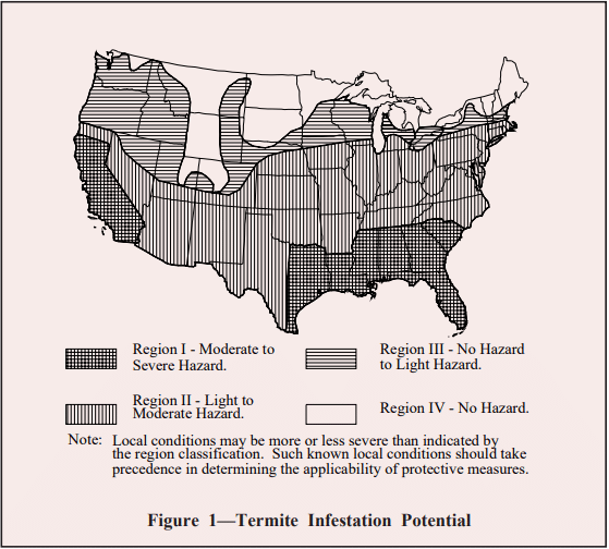
The level of termite control employed on a particular job should be consistent with the expected severity of the termite hazard. This level of severity for a particular location can be determined from local experience or from the state entomological authorities. Where such information is not available, Figure 1 may serve as a guide.
Figure 1—Termite Infestation Potential
SITE CONDITIONS
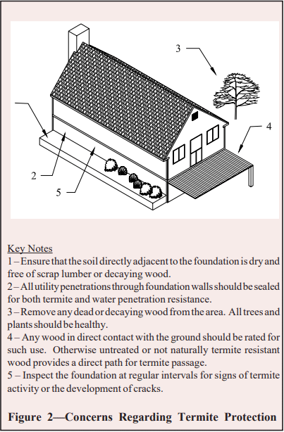
While preparing the site prior to construction, all roots, stumps, dead timber, and other wood debris should be removed from the site. Similarly, wood scraps from construction should be properly disposed. Leaving this material on site or in the backfill provides additional food sources for termites, attracting them and increasing the likelihood of infestation. Similarly, wood grade stakes or bracing stakes should be removed before or during a concrete placement and not be cast into the concrete. Leaving them in place attracts termites and provides a direct path for them through the concrete. Refer to Figure 2 for a summary of critical termite access areas.
Backfilling with a free draining soil, incorporating a subgrade drainage system, and installing proper above-grade water drainage will help keep the foundation and adjacent soil dry, providing a less hospitable environment for termites.
In extreme circumstances, subterranean termites may not require constant access to and from the adjacent soil. Where conditions exist such that wood remains continuously wet, termites do not need to return to the soil to obtain water. However, such conditions are rare if proper design and construction for water penetration resistance are adhered to.
Figure 2—Concerns Regarding Termite Protection
REDUCING ENTRY ROUTES
Once the termites have established a path, they have unimpeded access to the entire structure. Therefore, keeping termites out of the structure should always be the paramount objective. In addition to the obvious points of entry, such as wood in direct contact with the soil, other obscure (but critical) termite entry routes include:
through cracks in exposed wall faces or slabs. Termites are capable of moving through a crack only 1/32 inch (0.79 mm) wide;
direct access from soil under porches or patio slabs;
along the outside of pipes penetrating slabs or foundation walls; and
access tunnels on the interior or exterior of walls.
Minimum Clearance to Soil
It is desirable to keep wood elements as far as possible from the soil to minimize termite access. Nonstructural wood elements, such as wood siding and trim, should be kept a minimum of 6 inches (152 mm) from the soil surface. Structural wood framing, sill plates, and sheathing should be kept at least 8 inches (203 mm) above the soil, or as otherwise required by local building codes. However, if the nonstructural wood is in contact with the structural wood (which is generally the case), the 6 inch (152 mm) minimum clearance should be increased to 8 inches (203 mm). These general clearances do not apply to pressure-treated wood or other termite and decay resistant woods.
Minimizing Cracks
Proper structural design of foundation walls, footings, and slabs will help prevent structural cracking that may allow termite entry. In addition to preventing cracks due to structural overload, cracking due to concrete shrinkage also needs to be addressed. Due to fluctuations in the temperature and moisture content, all materials have a tendency to expand and contract over time. With concrete masonry foundations, the primary concern focuses on shrinkage resulting in the development of tensile stresses. This is because the tensile strength of concrete is relatively small compared to the compressive strength; therefore shrinkage may result in small cracks within the masonry.
It is normally not necessary to provide control joints in below grade residential concrete masonry basement walls. A control joint is a planned joint in a concrete masonry wall at regular intervals that accommodates shrinkage movement without unsightly, random cracking. The lack of a need for control joints is attributed to the relatively low range of thermal and moisture fluctuations occurring in below grade walls afforded by the soil adjacent to the walls and to the water resistant systems applied to basement walls. In most below grade basement wall construction, it is possible to provide a reinforced bond beam at or near the top of the wall in lieu of control joints to minimize crack development. The bond beam also provides a cap, preventing termites from coming up through the empty cores of ungrouted block and gaining entry into the building. Joint reinforcement embedded in the horizontal bed joints, usually at 16 inches on center, also provides additional tensile strength for the masonry and aids in crack control. It should be pointed out that horizontal reinforcement will not completely eliminate cracking, but it will hold the cracks so tightly together that the termites cannot get through.
Additional measures to reduce the shrinkage cracking potential of concrete masonry include keeping the walls dry during construction. Because drying shrinkage is a primary cause of cracking in concrete masonry walls, it is important to minimize the potential for wetting concrete masonry during the construction process. At the jobsite, concrete block should be stored so as to protect the units from absorbing ground water or precipitation. This includes storing block on pallets (or otherwise isolating block from direct contact with the ground) and covering the units with plastic or other water-repellent materials.
Concrete masonry units should be dry when laid. Some surface moisture is acceptable; however, saturated units should be allowed to dry out before placement in the wall. Concrete masonry units should never be wetted before or during placement in the wall, as may be customary with other types of masonry units.
At the end of each workday, a weatherproof membrane should be placed over uncompleted walls to protect the units from rain or snow. Placing a board on top of the membrane will help hold it in place and will prevent the membrane from sagging into the masonry cores and allowing water to collect. To limit concrete slab cracking, the recommendations of the American Concrete Institute (ref. 5) for quality concrete placement should be followed.
In basement walls, the dampproofing and waterproofing measures employed to reduce water penetration aid in the prevention of termite entry. Waterproofing and dampproofing systems require that the barrier be continuous to prevent water penetration into voids or open seams. Similarly, the barrier is typically carried above the finished grade level to prevent water entry between the barrier and the foundation wall. Cracks exceeding 0.02 inches (0.5 mm) should be repaired before applying a waterproof or damp-proof barrier. However, the repair of hairline cracks is typically not required, as most barriers will either fill or span these small openings. In addition, waterproofing and dampproofing systems should be applied to clean dry walls. In all cases, manufacturer’s directions should be carefully followed for proper installation.
Particular attention should be paid to reentrant corners at garages, porches, and fireplaces and to wall penetrations. Because stress concentrations develop at these intersections, pliable membranes and/or additional reinforcement are often recommended at these locations to span any poten- tial cracks or hold them tightly together.
Typical water penetration measures include coatings, sheet membranes, and drainage boards. Coatings are sprayed, trowelled, or brushed onto below-grade walls, providing a continuous barrier to water entry. Coatings should be applied to clean, structurally sound walls. Walls should be brushed or washed to remove dirt, oil, efflorescence, or other materials that may reduce the bond between the coating and the wall.
Sheet membranes and panels (drainage boards) are less dependent on workmanship and on surface preparation than coatings. Many of the membrane systems are better able to remain intact in the event of settlement or other movement of the foundation wall. All seams, terminations, and penetrations must be properly sealed. Care must also be exercised during the backfilling process to ensure that the barrier is not damaged.
In crawl space and stem walls, which typically are not treated on the exterior to prevent water entry as basement walls are, crack control measures become more important. In these cases, termites can enter the block through small cracks and move unseen up ungrouted cores. In these instances, solid grouting or capping of the walls is recommended.
Capping Concrete Masonry Walls
Various methods are used to seal the tops of masonry foundation walls. Should termites penetrate the face shell of a concrete masonry wall below, the cap prevents them from direct access to the wood superstructure. In reinforced construction, the masonry bond beam at the top of the wall serves as an effective cap, as shown in Figure 3.
Bond beam units are specifically designed to accommodate horizontal reinforcement and grout as shown in Figure 4. Bond beam units can be either solid bottom or open bottom. The latter requires a screen grout stop or expanded metal to contain the grout within the unit. A reinforced bond beam is preferred to solid units or solid bottom units with solid head joints since the reinforcement in bond beams will hold any cracks that form tightly together to prevent termite entry through the cracks.
Proper grouting procedures are important to ensure bond with the masonry units and void free areas in bond beams and cells to be filled. Grout should conform to the Specification for Grout for Masonry, ASTM C476 (ref. 7) or be specified to have a minimum compressive strength of 2,000 psi (13.8 MPa) at 28 days in accordance with the Specification for Masonry Structures, ACI 530.1/ASCE 6/TMS 402 (ref. 6). The Specification also requires enough water in the grout mixture to achieve a slump of 8 to 11 inches (203 to 279 mm) (ref. 6, 4) when tested in accordance with ASTM C143 Standard Test Method for Slump of Hydraulic Cement Concrete (ref. 9). See Figure 5.
This high slump is contrary to the principles of cast-in-place concrete where high slump levels lead to reduced strengths and higher shrinkage. Many engineers mistakenly try to apply this same analogy to masonry – lowering the water content in an effort to reduce shrinkage potential. However, in masonry construction, the high slump is critical as it allows the grout to be fluid enough to flow around reinforcement and completely fill all the voids (ref. 3, 4, and 6). The initial high water-to-cement ratio is reduced significantly as the masonry units absorb the excess water, resulting in higher strengths and low shrinkage properties despite the high initial water-to-cement ratio. Additionally, as the excess water is absorbed into the masonry units, some of the cement is drawn into the unit with the water creating excellent bond and reducing the formation of voids.
Grout should also be placed in lifts not exceeding 5 ft. (ref. 6). A lift is the layer of grout placed in a single continuous operation. Additionally, each lift should be consolidated with either a ¾ in. (19 mm) diameter low velocity vibrator. Consolidation eliminates voids, helping to ensure complete grout fill and good bond with the masonry units. After the water is absorbed from the grout mixture into the masonry (normally 3 to 10 minutes after placement, depending on the absorption characteristics of the unit and weather conditions), the grout should be reconsolidated to close the space left by the excess water that was absorbed (ref. 3). In any case, reconsolidation must be completed before the grout loses its plasticity.
Metal termite shields may be installed as a continuous barrier directly below the sill plate. If infestation occurs, termites are forced to build conspicuous access tunnels around the shield, making detection easy. Because termites require only a 1/32 inch (0.79 mm) gap for penetration, termite shields must be installed with great care to be effective. All seams must be soldered and all openings around anchor bolts and service lead-ins must be sealed. Because of the extreme care required to provide an impenetrable metal termite shield, they generally are not to be relied on for termite protection.
Figure 3—Masonry Bond Beam Cap
Figure 4—Bond Beam Units for Reinforced Construction
Figure 5—Masonry Requires a Fluid Grout; Slump to be between 8 and 11 in. (ref. 6)
Exterior Insulation
The rigid plastic foams that are often used to insulate crawl space and the exterior side of basement walls can allow termites to create undetectable tunnels and is prohibited for such use by some codes (ref. 7). An advantage of concrete masonry foundation walls is their ability to accommodate insulation within the cores of the masonry units where it is protected from direct contact with the soil. Either rigid foam insulation inserts, granular fill insulation, or foamedin-place insulation can be used for this purpose.
Additional Considerations for Crawl Spaces
Figure 6 illustrates termite control measures for crawl space foundations. Crawl space floors should be kept at or above the exterior finished grade to facilitate drainage in the crawl space. Where this is not possible, or on sites where water flows toward the building due to the site slope, area drains should be installed. Unless specified otherwise by local codes, wood girders should be at least 12 inches (305 mm) above the crawl space floor, and wood joists should be no closer than 18 inches (457 mm) to the soil. In all cases, enough clearance should be maintained to allow access to the crawl space for inspection.
Figure 6—Termite Control Measures for Crawl Space Foundations
CHEMICAL TREATMENTS
Numerous methods are available to create a pesticide barrier within the soil adjacent to a structure to prevent termite entry. Soil treatment before or during construction is often most effective as there is better access to the subgrade soil. If a slab-on-grade is also going to be used, the soil under the slab can also be pretreated. While post-construction treatment is far more common, it is also more difficult. Limited access to some areas may not allow for an effective chemical barrier to be established.
CONCLUSION
Concrete masonry is an ideal construction material to resist termites. It does not provide food to attract them, and provides a barrier to prevent termite entry. It is also very versatile with an almost endless amount of architectural shapes, sizes, textures, and colors available. An innovative, totally termite proof concrete masonry floor system utilizing a hidden steel bar joist supporting system is also available.
REFERENCES
Basement Manual: Design and Construction Using Concrete Masonry, CMU-MAN-002-01, Concrete Masonry & Hardscapes Association, 2001.
Concrete Masonry Homes: Recommended Practices. U.S. Department of Housing and Urban Development, Office of Policy Development and Research, 1999.
Concrete masonry is a popular building material because of its strength, durability, economy, and its resistance to fire, noise, and insects. To function as designed however, concrete masonry buildings must be constructed properly.
This TEK provides a brief overview of the variety of materials and construction methods currently applicable to concrete masonry. In addition, a typical construction sequence is described in detail.
MATERIALS
The constituent masonry materials: concrete block, mortar, grout, and steel, each contribute to the performance of a masonry structure. Concrete masonry units provide strength, durability, fire resistance, energy efficiency, and sound attenuation to a wall system. In addition, concrete masonry units are manufactured in a wide variety of sizes, shapes, colors, and architectural finishes achieve any number of appearances and functions. The Concrete Masonry Shapes and Sizes Manual (ref. 4) illustrates a broad sampling of available units.
While mortar constitutes approximately 7% of a typical masonry wall area, its influence on the performance of a wall is significant. Mortar bonds the individual masonry units together, allowing them to act as a composite structural assembly. In addition, mortar seals joints against moisture and air leakage and bonds to joint reinforcement, anchors, and ties to help ensure all elements perform as a unit.
Grout is used to fill masonry cores or wall cavities to improve the structural performance and/or fire resistance of masonry. Grout is most commonly used in reinforced construction, to structurally bond the steel reinforcing bars to the masonry, allowing the two elements to act as one unit in resisting loads.
Reinforcement incorporated into concrete masonry structures increases strength and ductility, providing increased resistance to applied loads and, in the case of horizontal reinforcement, to shrinkage cracking.
Specifications governing material requirements are listed in Table 1.
Table 1—Masonry Material Specifications
CONSTRUCTION METHODS
Mortared Construction
Most concrete masonry construction is mortared construction, i.e., units are bonded together with mortar. Varying the bond or joint pattern of a concrete masonry wall can create a wide variety of interesting and attractive appearances. In addition, the strength of the masonry can be influenced by the bond pattern. The most traditional bond pattern for concrete masonry is running bond, where vertical head joints are offset by half the unit length.
Excluding running bond construction, the most popular bond pattern with concrete masonry units is stack bond. Although stack bond typically refers to masonry constructed so that the head joints are vertically aligned, it is defined as masonry laid such that the head joints in successive courses are horizontally offset less than one quarter the unit length (ref. 2). Concrete Masonry Bond Patterns (ref. 3), shows a variety of bond patterns and describes their characteristics.
Dry-Stacked Construction
The alternative to mortared construction is dry-stacked (also called surface bonded) construction, where units are placed without any mortar, then both surfaces of the wall are coated with surface bonding material. Shims or ground units are used to maintain elevations. This construction method results in faster construction, and is less dependent on the skill of the laborer than mortared construction. In addition, the surface bonding coating provides excellent rain penetration resistance. Surface Bonded Concrete Masonry Construction (ref. 9), contains further information on this method of construction.
CONSTRUCTION SEQUENCE
Mixing Mortar
To achieve consistent mortar from batch to batch, the same quantities of materials should be added to the mixer, and they should be added in the same order. Mortar mixing times, placement methods, and tooling must also be consistent to achieve uniform mortar for the entire job.
In concrete masonry construction, site-mixing of mortar should ideally be performed in a mechanical mixer to ensure proper uniformity throughout the batch. Mortar materials should be placed in the mixer in a similar manner from batch to batch to maintain consistent mortar properties. Typically, about half the mixing water is added first into a mixer. Approximately half the sand is then added, followed by any lime. The cement and the remainder of the sand are then added. As the mortar is mixed and begins to stiffen, the rest of the water is added. Specification for Masonry Structures (ref. 7) requires that these materials be mixed for 3 to 5 minutes. If the mortar is not mixed long enough, the mortar mixture may not attain the uniformity necessary for the desired performance. A longer mixing time can increase workability, water retention, and board life.
The mortar should stick to the trowel when it is picked up, and slide off the trowel easily as it is spread. Mortar should also hold enough water so that the mortar on the board will not lose workability too quickly, and to allow the mason to spread mortar bed joints ahead of the masonry construction. The mortar must also be stiff enough to initially support the weight of the concrete masonry units.
To help keep mortar moist, the mortarboard should be moistened when a fresh batch is loaded. When mortar on the board does start to dry out due to evaporation, it should be retempered. To retemper, the mortar is mixed with a small amount of additional water to improve the workability. After a significant amount of the cement has hydrated, retempering will no longer be effective. For this reason, mortar can be retempered for only 1 ½ to 2 ½ hours after initial mixing, depending on the site conditions. For example, dry, hot, and windy conditions will shorten the board life, and damp, cool, calm conditions will increase the board life of the mortar. Mortar should be discarded if it shows signs of hardening or if 2 ½ hours have passed since the original mixing.
Placing Mortar
Head and bed joints are typically ⅜ in. (10 mm) thick, except at foundations. Mortar should extend fully across bedding surfaces of hollow units for the thickness of the face shell, so that joints will be completely filled. Solid units are required to be fully bedded in mortar.
Although it is important to provide sufficient mortar to properly bed concrete masonry units, excessive mortar should not extend into drainage cavities or into cores to be grouted. For grouted masonry, mortar protrusions extending more than ½ in. (13 mm) into cells or cavities to be grouted should be removed (ref. 7).
The Importance of Laying to the Line
Experienced masons state that they can lay about five times as many masonry units when working to a mason line than when using just their straightedge. The mason line gives the mason a guide to lay the block straight, plumb, at the right height, and level. The line is attached so that it gives a guide in aligning the top of the course.
If a long course is to be laid, a trig may be placed at one or more points along the line to keep the line from sagging. Before work begins, the mason should check to see that the line is level, tight, and will not pull out.
Each mason working to the same line needs to be careful not to lay a unit so it touches the line. This will throw the line off slightly and cause the rest of the course to be laid out of alignment. The line should be checked from time to time to be certain it has remained in position.
Placement of Concrete Masonry Units
PLACING UNITS
The Foundation
Before building the block wall, the foundation must be level, and clean so that mortar will properly adhere. It must also be reasonably level. The foundation should be free of ice, dirt, oil, mud, and other substances that would reduce bond.
Laying Out the Wall
Taking measurements from the foundation or floor plan and transferring those measurements to the foundation, footing, or floor slab is the first step in laying out the wall.
Once two points of a measurement are established, corner to corner, a chalk line is marked on the surface of the foundation to establish the line to which the face of the block will be laid. Since a chalk line can be washed away by rain, a grease crayon, line paint, nail or screwdriver can mark the surface for key points along the chalk line, and a chalk line re-snapped along these key points. After the entire surface is marked for locations of walls, openings, and control joints, a final check of all measurements should be made.
The Dry Run—Stringing Out The First Course
Starting with the corners, the mason lays the first course without any mortar so a visual check can be made between the dimensions on the floor or foundation plan and how the first course actually fits the plan. During this dry layout, concrete blocks will be strung along the entire width and length of the foundation, floor slab, and even across openings. This will show the mason how bond will be maintained above the opening. It is helpful to have ⅜ in. (10 mm) wide pieces of wood to place between block as they are laid dry, to simulate the mortar joints.
At this dry run the mason can check how the block will space for openings which are above the first course—windows, etc., by taking away block from the first course and checking the spacing for the block at the higher level. These checks will show whether or not units will need to be cut. Window and door openings should be double checked with the window shop drawings prior to construction.
When this is done, the mason marks the exact location and angle of the corners. It is essential that the corner be built as shown on the foundation or floor plan, to maintain modular dimensions.
Laying the Corner Units
Building the corners is the most precise job facing the mason as corners will guide the construction of the rest of the wall. A corner pole can make this job easier. A corner pole is any type of post which can be braced into a true vertical position and which will hold a taut mason’s line without bending. Corner poles for concrete block walls should be marked every 4 or 8 in. (102 to 203 mm), depending on the course height, and the marks on both poles must be aligned such that the mason’s line is level between them.
Once the corner poles are properly aligned, the first course of masonry is laid in mortar. Typically, a mortar joint between ¼ and ¾ in. (6.4 to 19 mm) is needed to make up for irregularities of the footing surface. The initial bed joint should be a full bed joint on the foundation, footing, or slab. In some areas, it is common practice to wet set the initial course of masonry directly in the still damp concrete foundation.
Where reinforcing bars are projecting from the foundation footing or slab, the first course is not laid in a full mortar bed. In this case, the mason leaves a space around the reinforcing bars so that the block will be seated in mortar but the mortar will not cover the area adjacent to the dowels. This permits the grout to bond directly to the foundation in these locations.
After spreading the mortar on the marked foundation, the first block of the corner is carefully positioned. It is essential that this first course be plumb and level.
Once the corner block is in place, the lead blocks are set— three or four blocks leading out from each side of the corner. The head joints are buttered in advance and each block is lightly shoved against the block in place. This shove will help make a tighter fit of the head joint, but should not be so strong as to move the block already in place. Care should be taken to spread mortar for the full height of the head joint so voids and gaps do not occur.
If the mason is not working with a corner pole, the first course leads are checked for level, plumb, and alignment with a level.
Corners and leads are usually built to scaffold height, with each course being stepped back one half block from the course below. The second course will be laid in either a full mortar bed or with face shell bedding, as specified.
Laying the Wall
Each course between the corners can now be laid easily by stretching a line between. It should be noted that a block has thicker webs and face shells on top than it has on the bottom. The thicker part of the webs should be laid facing up. This provides a hand hold for the mason and more surface area for mortar to be spread. The first course of block is thereafter laid from corner to corner, allowing for openings, with a closure block to complete the course. It is important that the mortar for the closure block be spread so all edges of the opening between blocks and all edges of the closure block are buttered before the closure block is carefully set in place. Also, the location of the closure block should be varied from course to course so as not to build a weak spot into the wall.
The units are leveled and plumbed while the mortar is still soft and pliable, to prevent a loss of mortar bond if the units need to be adjusted.
As each block is put in place, the mortar which is squeezed out should be cut off with the edge of the trowel and care should be taken that the mortar doesn’t fall off the trowel onto the wall or smear the block as it is being taken off. Should some mortar get on the wall, it is best to let it dry before taking it off.
All squeezed out mortar which is cut from the mortar joints can either be thrown back onto the mortar board or used to butter the head joints of block in place. Mortar which has fallen onto the ground or scaffold should never be reused.
At this point, the mason should:
Use a straightedge to assure the wall is level, plumb and aligned.
Be sure all mortar joints are cut flush with the wall, awaiting tooling, if necessary.
Check the bond pattern to ensure it is correct and that the spacing of the head joints is right. For running bond, this is done by placing the straightedge diagonally across the wall. If the spacing of head joints is correct, all the edges of the block will be touched by the straightedge.
Check to see that there are no pinholes or gaps in the mortar joints. If there are, and if the mortar has not yet taken its first set, these mortar joint defects should be repaired with fresh mortar. If the mortar has set, the only way they can be repaired is to dig out the mortar joint where it needs repairing, and tuckpoint fresh mortar in its place.
Tooling Joints
When the mortar is thumbprint hard, the head joints are tooled, then the horizontal joints are finished with a sled runner and any burrs which develop are flicked off with the blade of the trowel. When finishing joints, it is important to press firmly, without digging into the joints. This compresses the surface of the joint, increasing water resistance, and also promotes bond between the mortar and the block. Unless otherwise required, joints should be tooled with a rounded jointer, producing a concave joint. Once the joints are tooled, the wall is ready for cleaning.
Cleanup
Masonry surfaces should be cleaned of imperfections that may detract from the final appearance of the masonry structure including stains, efflorescence, mortar droppings, grout droppings, and general debris.
Cleaning is most effective when performed during the wall construction. Procedures such as skillfully cutting off excess mortar and brushing the wall clean before scaffolding is raised, help reduce the amount of cleaning required.
When mortar does fall on the block surface, it can often be removed more effectively by letting it dry and then knocking it off the surface. If there is some staining on the face of the block, it can be rubbed off with a piece of broken block, or brushed off with a stiff brush.
Masons will sometimes purposefully not spend extra time to keep the surface of the masonry clean during construction because more aggressive cleaning methods may have been specified once the wall is completed. This is often the case for grouted masonry construction where grout smears can be common and overall cleaning may be necessary.
The method of cleaning should be chosen carefully as aggressive cleaning methods may alter the appearance of the masonry. The method of cleaning can be tested on the sample panel or in an inconspicuous location to verify that it is acceptable.
Specification for Masonry Structures (ref. 7) states that all uncompleted masonry work should be covered at the top for protection from the weather.
DIMENSIONAL TOLERANCES
While maintaining tight construction tolerances is desirable to the appearance, and potentially to the structural integrity of a building, it must be recognized that factors such as the condition of previous construction and nonmodularity of the project may require the mason to vary the masonry construction slightly from the intended plans or specifications. An example of this is when a mason must vary head or bed joint thicknesses to fit within a frame or other preexisting construction. The ease and flexibility with which masonry construction accommodates such change is one advantage to using masonry. However, masonry should still be constructed within certain tolerances to ensure the strength and appearance of the masonry is not compromised.
Specification for Masonry Structures (ref. 7) contains site tolerances for masonry construction which allow for deviations in the construction that do not significantly alter the structural integrity of the structure. Tighter tolerances may be required by the project documents to ensure the fi- nal overall appearance of the masonry is acceptable. If site tolerances are not being met or cannot be met due to previous construction, the Architect/Engineer should be notified.
Mortar Joint Tolerances
Mortar joint tolerances are illustrated in Figure 1. Al- though bed joints should be constructed level, they are permitted to vary by ± ½ in. (13 mm) maximum from level provided the joint does not slope more than ± ¼ in. (6.4 mm) in 10 ft (3.1 m).
Collar joints, grout spaces, and cavity widths are permitted to vary by –¼ in. to +⅜ in. (6.4 to 9.5 mm). Provisions for cavity width are for the space between wythes of non-composite masonry. The provisions do not apply to situations where the masonry extends past floor slabs or spandrel beams.
Figure 1—Mortar Joint Tolerances
Dimensions of Masonry Elements
Figure 2 shows tolerances that apply to walls, columns, and other masonry building elements. It is important to note that the specified dimensions of concrete masonry units are ⅜ in. (9.5 mm) less than the nominal dimensions. Thus a wall specified to be constructed of 8 in. (203 mm) concrete masonry units should not be rejected because it is 7 ⅝ in. (194 mm) thick, less than the apparent minimum of 7 ¾ in. (197 1 mm) (8 in. (203 mm) minus the ¼ in. (6.4 mm) tolerance). Instead the tolerance should be applied to the 7 ⅝ in. (194 mm) specified dimension.
Figure 2—Element Cross Section and Elevation Tolerances
Plumb, Alignment, and Levelness of Masonry Elements
Tolerances for plumbness of masonry walls, columns, and other building elements are shown in Figure 3. Masonry building elements should also maintain true to a line within the same tolerances as variations from plumb.
Columns and walls continuing from one story to another may vary in alignment by ± ¾ in. (19 mm) for nonloadbearing walls or columns and by ± ½ in. (13 mm) for bearing walls or columns.
The top surface of bearing walls should remain level within a slope of ± ¼ in. (6.4 mm) in 10 ft (3.1 m), but no more than ± ½ in. (13 mm).
Figure 3—Permissible Variations From Plumb
Location of Elements
Requirements for location of elements are shown in Figures 4 and 5.
Figure 4—Location Tolerances in Plan
Figure 5—Location Tolerances in Story Height
REFERENCES
Building Block Walls, VO 6. National Concrete Masonry Association, 1988.
Building Code Requirements for Masonry Structures, ACI 530-99/ASCE 5-99/TMS 402-99. Reported by the Masonry Standards Joint Committee, 1999.
Concrete Masonry Bond Patterns, TEK 14-06, Concrete Masonry & Hardscapes Association, 2004.
Nolan, K. J. Masonry & Concrete Construction. Craftsman Book Company, 1982.
Specification for Masonry Structures, ACI 530.1-99/ASCE 6-99/TMS 602-99. Reported by the Masonry Standards Joint Committee, 1999.
Standard Specification for Loadbearing Concrete Masonry Units, ASTM C 90-00. American Society for Testing and Materials, 2000.